

Trackmaster FVX325, TMX435, FVX325C, TMX425CP, FVX325CP Field Service Manual
...
Legal Notice:
Use of the document and the information contained in it is strictly reserved for current Philips
personnel and Philips customers who have a current and valid license from Philips for use by
the customer’s designated in-house service
employee on
equipment located at the
customer’s designated site. This document and the information contained in it is proprietary
and confidential information of Philips Healthcare ("Philips") and may not be reproduced,
copied in whole or in part, adapted, modified, disclosed to others, or disseminated without
the prior written permission of the Philips Legal Department. This document is intended to
be (a.) used by customers and is licensed to them as part of their Philips equipment
purchase or (b.) used to meet regulatory commitments as required by the FDA under 21
CFR 1020.30 (and any amendments to it) and other local regulatory requirements. Use of
this document by unauthorized persons is strictly prohibited.
This document must be returned to Philips when the user is no longer licensed and in any
event upon Philips’ first written request. PHILIPS PROVIDES THIS DOCUMENT WITHOUT
WARRANTY OF ANY KIND, EITHER IMPLIED OR EXPRESSED, INCLUDING, BUT NOT
LIMITED TO, THE IMPLIED WARRANTIES OF MERCHANTABILITY AND FITNESS FOR A
PARTICULAR PURPOSE. Philips has taken care to ensure the accuracy of the information
contained within this document. However, Philips assumes no liability for errors or
omissions, and reserves the right to make changes without further notice to any products
herein to improve reliability, function, or design. Philips may make improvements or changes
in the product(s)
CSIP Level 0
© 2013 Koninklijke Philips N.V.
described
in this document at
any time.
All rights reserved.

TREADMILL
FIELD SERVICE MANUAL
FVX No Control
FVX__C Manual Control
FVX__CP Programmable Control
TMX No Control
TMX__C Manual Control
TMX__CP Programmable Control
Revision Level 5 August, 2006
Refer equipment servicing to Full Vision, Inc. authorized service
personnel only. Any unauthorized attempt to repair equipment under
warranty voids that warranty.


TRACKMASTER
CONTACT INFORMATION
SERVICE DEPARTMENT
PARTS DEPARTMENT
Models: FVX325, FVX325C, FVX325CP
TMX435, TMX425C, TMX425CP
Service Line: 316-283-8110
Address: Full Vision Inc.
3017 Full Vision Drive
Newton, Ks 67114
Models: FVX325, FVX325C, FVX325CP
TMX435, TMX425C, TMX425CP
Service Line: 316-283-8110
Address: Full Vision Inc.
3017 Full Vision Drive
Newton, Ks 67114
Authorized Representative
In European Union
(Regulatory affairs only)
Emergo Europe
Molenstraat 15
2513 BH The Hague
The Netherlands
(31) (0) 70 345-8570 telephone
(31) (0) 70 345-7299 fax
August, 2006 FVX, TMX Series Service Manual i

TRACKMASTER
TMX325 Series Treadmill
Field Service Manual
Part #317-07189 – 317-07191
TMX425 Series Treadmill
Field Service Manual
Part #317-07130 – 317-07135
TRACKMASTER TREADMILLS
BY
FULL VISION INC.
Original Publication Date 9/5/02
Note: Due to continuing product innovation, specifications in this manual are subject
to change without notice.
Printed in USA. TRACKMASTER®is a registered trademark of JAS Manufacturing Co.,
Inc. TRACKMASTER is protected by the following US Patents: 5320589, 5431613. All
other patents pending. Polar® is the registered trademark of Polar CIC Inc.
ii FVX, TMX Series Service Manual August, 2006

TRACKMASTER
Contents
Chapter 1 Introduction ............................................... 1-1
Notices ..................................................................... 1-1
Drawings ................................................................... 1-2
Directional Orientation ....................................................... 1-2
Responsibility of manufacturer ............................................... 1-2
Equipment Symbols ......................................................... 1-3
Chapter 2 Service Information ....................................... 2-1
Service Requirements......................................................... 2-1
Equipment Identification...................................................... 2-1
Serial Number Location & Identification ....................................... 2-2
Explanation of Serial Decal Information........................................ 2-2
Chapter 3 General Description ...................................... 3-1
Intended Use................................................................. 3-1
Motor Drive Systems......................................................... 3-1
Elevation Systems ........................................................... 3-1
Electronic Assembly.......................................................... 3-1
Power Supply Relay Board Detail.............................................. 3-2
Chapter 4 Preparation for Use .......................................4-1
Safe Handling Guidelines ..................................................... 4-1
FVX325 Series Initial Setup and Assembly ..................................... 4-2
TMX425 Series Initial Setup and Assembly..................................... 4-3
Check Unit for Operation ..................................................... 4-4
Test Plug Procedure .......................................................... 4-5
Belt Tracking and Alignment.................................................. 4-6
Belt Tension Adjustment...................................................... 4-7
Drive Belt Tension Adjustment................................................ 4-8
Connector and Switch Locations............................................... 4-9
Power Requirements.........................................................4-10
Operating and Storage Condition Recommendations............................ 4-11
Installation After Long Period of Storage ......................................4-11
Chapter 5 Operating Instructions ...................................5-1
Electrical Safety Tests ........................................................ 5-1
Operating Controls ........................................................... 5-1
Controlling the Treadmill ..................................................... 5-1
Safe Operation of Treadmill................................................... 5-2
Emergency Stop Button Check ................................................ 5-3
Operation of Manual Treadmill Control ........................................ 5-4
Manual Treadmill Self Test Procedure ......................................... 5-5
FVX325C, TMX425C Manual Treadmill Controller Windows 98 and Older....... 5-8
FVX325C, TMX425C Manual Treadmill Controller Windows 95 and Newer...... 5-8
Manual Treadmill Control Console Programming Mode ......................... 5-9
Operation of Programmable Treadmill Control ................................ 5-14
Programmable Treadmill Self Test Procedure ..................................5-21
FVX325CP, TMX425CP Programmable Treadmill Controller...................5-26
FVX325CP, TMX425CP Programmable Treadmill Controller...................5-26
Programmable Treadmill Control Console Programming Mode .................5-27
August, 2006 FVX, TMX Series Service Manual iii

TRACKMASTER
Chapter 6 Preventative Maintenance ................................6-1
Inspection and Cleaning ...................................................... 6-1
Belt Cleaning & Inspection.................................................... 6-2
Calibration................................................................... 6-2
Belt Speed Calibration ....................................................... 6-3
FVX, TMX Series Verifying Belt Speed Calibration in the Field ................. 6-4
FVX325, TMX425 Series Elevation Calibration Procedure No Control Unit....... 6-5
FVX325C, TMX425C Series Elevation Calibration
Procedure Manual Control Unit................................................ 6-8
FVX324CP, TMX425CP Series Elevation Calibration
Procedure Programmable Control Unit........................................ 6-10
Elevation Screw Lubrication ................................................. 6-12
Chapter 7 Troubleshooting .......................................... 7-1
Trouble Shooting Guide ...................................................... 7-1
Power Supply & Drive Circuit Board (FG309).................................. 7-2
Power Supply ................................................................ 7-3
Output from Control Console to FG309 ........................................ 7-4
FG309 Belt Start ....................................................... 7-4
FG309 Change Belt Speed .............................................. 7-4
FG309 Elevation Up.................................................... 7-5
FG309 Elevation Down................................................. 7-5
Input from FG309 to Control Console.......................................... 7-6
Elevation Sensor ....................................................... 7-6
Speed Sensor........................................................... 7-6
Chapter 8 Removal and Replacement of Components ............8-1
Hood Removal Procedure FVX Series ......................................... 8-1
Hood Removal Procedure TMX Series ......................................... 8-2
Drive Motor Replacement FVX Series......................................... 8-3
Drive Motor Replacement TMX Series......................................... 8-5
Front Roller Replacement FVX/TMX Series.................................... 8-8
Rear Roller Replacement FVX/TMX Series ................................... 8-10
Running Belt Replacement FVX Series ....................................... 8-12
Running Belt Replacement TMX Series ....................................... 8-14
Running Deck Replacement FVX Series ...................................... 8-16
Running Deck Replacement TMX Series ...................................... 8-17
Deck Cushion Replacement FVX Series....................................... 8-18
Deck Cushion Replacement TMX Series ...................................... 8-19
Motor Drive Belt Replacement FVX Series.................................... 8-20
Motor Drive Belt Replacement TMX Series ................................... 8-22
Elevation Actuator Replacement/Adjustment .................................. 8-24
Power Supply Relay Board Replacement FVX Series .......................... 8-26
Power Supply Relay Board Replacement TMX Series .......................... 8-28
Circuit Breaker Replacement................................................. 8-30
Inverter Drive Replacement FVX Series....................................... 8-31
Inverter Drive Replacement TMX Series...................................... 8-33
iv FVX, TMX Series Service Manual August, 2006

TRACKMASTER
Chapter 9 Product Requirements
FVX, TMX Smart Power Supply ..........................9-1
Introduction .................................................................. 9-1
Scope........................................................................9-1
Operational Overview ........................................................ 9-1
Software Requirements........................................................9-2
Speed Control .......................................................... 9-2
Elevation Control.......................................................9-2
Communication......................................................... 9-2
Command Protocol......................................................9-3
Input Commands........................................................9-3
Input Command Acknowledgement ......................................9-3
Status Request..........................................................9-4
Status Response ........................................................ 9-4
Communication Notes...................................................9-5
Self Test Mode ......................................................... 9-6
Calibration.............................................................9-6
Hardware Requirements.......................................................9-7
Electrical Inputs ........................................................9-7
Electrical Outputs.......................................................9-7
Electrical Connections...................................................9-8
Physical Requirements & Restrictions ....................................9-8
Chapter 10 Production Qualification Description
FG302 Smart Power Supply ............................ 10-1
Test Fixture ................................................................ 10-1
Test Fixture Connections....................................................10-1
PC Directed Test Step....................................................... 10-2
Board Power Test........................................................... 10-2
Test Grade................................................................. 10-2
Test Belt................................................................... 10-2
Test EEprom............................................................... 10-2
Test Voltage Selection Switch ............................................... 10-2
Communication Test........................................................ 10-2
FG302 Diagram ............................................................ 10-3
Chapter 11 Leeson Inverter ......................................... 11-1
Leeson Speedmaster Self-Test ............................................... 11-1
Leeson Inverter Inspection Sheet............................................. 11-2
Inverter Parameters/Software Version 301 .................................... 11-3
Inverter Parameters/Software Version 402 .................................... 11-6
Inverter Parameters/Software Version 403 .................................... 11-8
Inverter Parameters/Software Version 403 & Later ........................... 11-10
August, 2006 FVX, TMX Series Service Manual v

TRACKMASTER
Chapter 12 Established Component Replacement Times ........ 12-1
FVX, TMX Component Replacement Times ...................................12-1
Chapter 13 Parts List with Part Numbers .......................... 13-1
FVX Series Inverter Assembly 220V Software Version 402/402/404 ............ 13-1
TMX Series Inverter Assembly 220V Software Version 301.................... 13-2
TMX Series Inverter Assembly 115V Software Version 301.................... 13-3
TMX Series Inverter Assembly 220V Software Version 402/403/404 ........... 13-4
FVX Series Inverter Assembly 110V Software Version 402/403/403 ............ 13-5
Motor Mount Assembly..................................................... 13-6
Alternative Motor Mount Assembly FVX/TMX Series......................... 13-7
FVX Series Movable ESB Assembly......................................... 13-8
TMX Series Movable ESB Assembly......................................... 13-9
FVX/TMX Series Elevation Assembly ...................................... 13-10
FVX/TMX Line Reactor Assembly CE Component........................... 13-11
FVX325 Series 220V Motor Pan Assembly w/ CE Components ............... 13-12
FVX325 Series Elevation Assembly......................................... 13-15
FVX325 Series Frame Assembly............................................ 13-16
FVX325 Series Final Assembly ............................................. 13-18
TMX425 Series 115V Motor Pan Assembly.................................. 13-20
TMX425 Series 115V Motor Pan Assembly w/CE Components ............... 13-22
TMX425 Series 220V Motor Pan Assembly.................................. 13-24
TMX425 Series 220V Motor Pan Assembly w/CE Components ............... 13-26
TMX Series w/ CE Option #317-01784...................................... 13-28
TMX425 Series Frame Assembly ........................................... 13-29
TMX425 Series Running Deck Assembly.................................... 13-31
TMX425 Series Final Assembly ............................................ 13-33
Chapter 14 Flowcharts & Instructions for Trouble Shooting ..... 14-1
Flowcharts ................................................................. 14-1
Power Distribution 120 VAC Flowchart 1A................................ 14-1
Power Distribution 208-240 VAC Flowchart 1B............................ 14-2
Power Distribution 120 VAC Flowchart 1C................................ 14-3
Power Distribution 208-240 VAC Flowchart 1D............................ 14-4
Power Distribution Low Voltage Power Supply Flowchart 1E ............... 14-5
Belt Start Command Flowchart 1 2A ...................................... 14-6
Speed Sensor Fault Isolation FVX, TMX Series 2A1........................ 14-7
FVX, TMX No Control Series Belt Motor Start Operation–Self Test 2B ...... 14-8
FVX, TMX Control Series Belt Motor Start Operation-Self Test 2C.......... 14-9
Leeson Speedmaster – Parameter Inspection and Self-Test 2D.............. 14-10
Treadmill Elevation Flowchart 3A ....................................... 14-11
Treadmill No Elevation FVX, TMX No Control Series
Elevation Flowchart 3B ................................................. 14-12
Treadmill No Elevation FVX, TMX Control Series
vi FVX, TMX Series Service Manual August, 2006
-

TRACKMASTER
Chapter 14 Flowcharts & Instructions for Trouble Shooting ..... 14-1
Instruction for Trouble Shooting ............................................ 14-14
Power Distribution Fault Isolation (1)120 VAC ........................... 14-14
Power Distribution Fault Isolation (2) 208-240 VAC ...................... 14-14
Power Distribution Fault Isolation (3)120 VAC ........................... 14-14
Power Distribution Fault Isolation (4) 208-240 VAC ...................... 14-14
FG 309 Elevation and Power Supply A/C Voltage Distribution
Fault Isolation Instruction ............................................... 14-15
FG 302 Elevation and Power Supply A/C Voltage Distribution
Fault Isolation Instruction ............................................... 14-16
ESB Circuit Fault Isolation Instruction.................................... 14-17
Speed Sensor Fault Isolation FVX, TMX No Control Series................ 14-18
Interior Interface Cable Fault Isolation FVX, TMX No Control Series....... 14-18
Perform Incorrect Belt Speed Fault Isolation FVX, TMX No Control Series . 1 4 -18
Speed Sensor Fault Isolation FVX, TMX Control Series ................... 14-18
Speed V-Guide 10.92’ (3.33m)........................................... 14-19
Speed V-Guide 8.45’ (2.56m)............................................ 14-19
Perform FVX, TMX Manual Control Series Incorrect
Belt Speed Fault Isolation ............................................... 14-20
Perform FVX, TMX Programmable Control Series Incorrect
Belt Speed Fault Isolation ............................................... 14-20
Test Plug Procedure (FVX, TMX No Control Series Units Only) ........... 14-21
Elevation Sensor FVX, TMX No Control Series Fault Isolation Procedure . . . 1 4 -21
Elevation Sensor FVX, TMX Control Series Fault Isolation Procedure ...... 14-21
Chapter 15 Treadmill Report/Service Log .......................... 15-1
TMX425 Series Maintenance Inspection Report ............................... 15-1
FVX325 Series Maintenance Inspection Report ............................... 15-3
Emergency Stop Button (ESB) Location Drawing............................. 15-5
FVX325 Series Treadmill Field Service Manual Log Sheet..................... 15-6
TMX425 Series Treadmill Field Service Manual Log Sheet .................... 15-7
August, 2006 FVX, TMX Series Service Manual vii

TRACKMASTER
viii FVX, TMX Series Service Manual August, 2006

TRACKMASTER
Introduction
The purpose of this service manual is to supply authorized service providers and
qualified technicians the information needed to maintain and repair the
TRACKMASTER
electronic theories is required along with a basic understanding of hand tools and there
use.
A multi meter capable of measuring AC/DC voltages up to 240 volts and the ability to
perform continuity checks is required. An amp probe capable of reading up to 20 amps is
recommended.
Specific hand tools required are listed at the beginning of all removal and replacement
procedures. A complete list of all tools required in this manual can be found in the
service technician’s feedback section of this manual.
This manual includes: maintenance and trouble shooting guides, parts list, illustrations of
assembly parts and some schematics.
1
®
medical treadmills. A minimal understanding of basic electric and
Notices
Note
Three different levels of notices throughout this manual alert you to important
information: Note, Caution, and Warning.
Note statements provide additional information, such as the following:
Note: For maximum safety and efficiency, the treadmill must have its own dedicated
power outlet.
August, 2006 FVX, TMX Series Service Manual 1-1

TRACKMASTER
Caution
CAUTION Do not use silicone sprays to wax your treadmill deck. Using silicone sprays may void
Warning
WARNING Never open the hood of the treadmill while it is plugged into a power outlet. Line voltage
Drawings
Directional Orientation
Responsibility of Manufacturer
Caution notices inform you of potential hazards that could result in equipment damage or
injury, such as the following:
the warranty. Such sprays can bring about surface changes that cause you to slip.
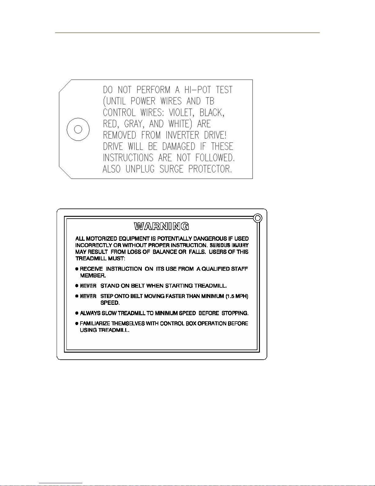
Warning notices alert readers to hazards that will result in serious injury or death, such as
the following:
will cause severe injury or death.
Chapter 13, assembly drawings.
References to left, right, front, and rear are based on the assumption that you are standing
on the treadmill, facing forward.
Full Vision, Inc. is responsible for the effects of safety reliability, and performance only
if:
• Assembly operations, extensions, readjustments, modifications or repairs are carried
out by persons authorized by Full Vision, Inc.
• The electric installation of the relevant room complies with the requirements of the
appropriate regulations.
• The equipment is used in accordance with the instruction for use.
1-2 FVX, TMX Series Service Manual August, 2006
TRACKMASTER
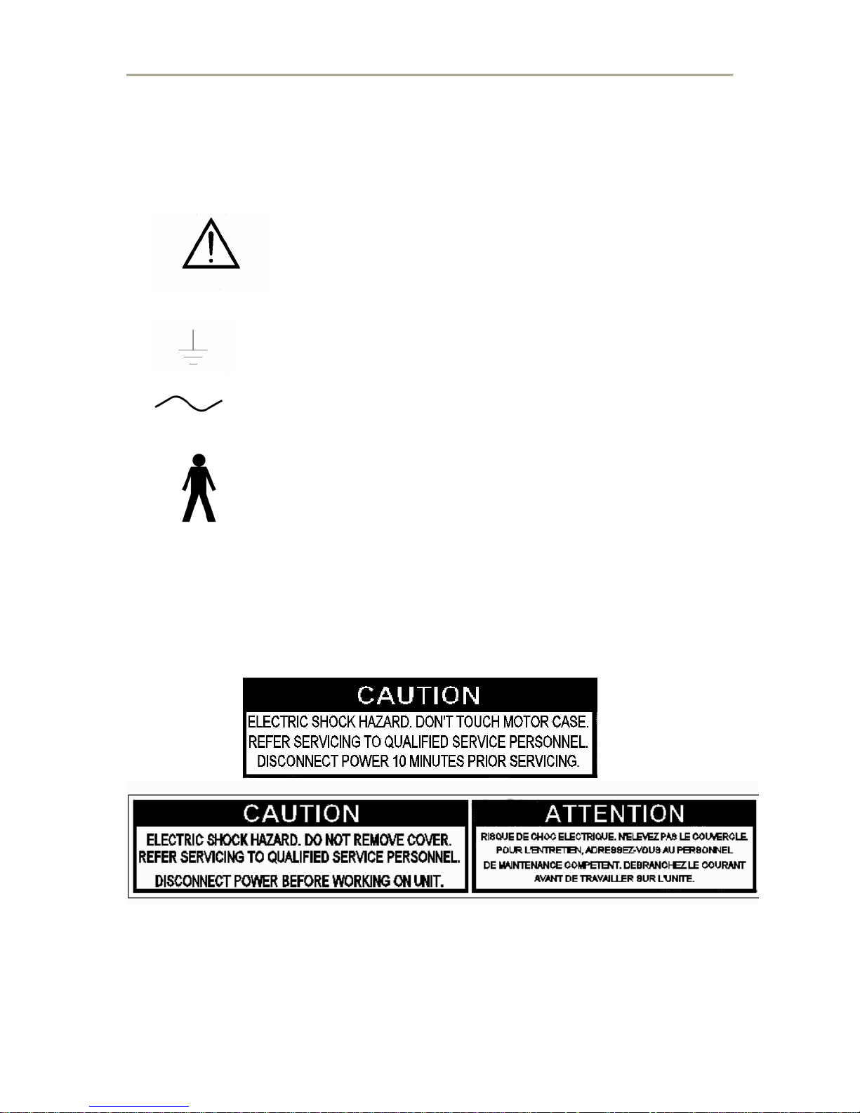
Equipment symbols
The following symbols appear on the treadmill.
This symbol means that you must pay attention to the documents
delivered with this equipment. It calls notice to the things to
which you must pay special attention during operation and when
the equipment is operated in conjunction with other equipment.
Protective earth (ground)
Alternating current
Type B equipment is suitable for intentional
external and internal application to the
patient, excluding direct conductive
connection to the patient heart.
Warning and caution symbols
August, 2006 FVX, TMX Series Service Manual 1-3
TRACKMASTER
1-4 FVX, TMX Series Service Manual August, 2006

TRACKMASTER
Service Information
Service Requirements
Refer equipment servicing to Full Vision, Inc. authorized service personnel only. Any
unauthorized attempt to repair equipment under warranty voids that warranty.
It is the responsibility of the user to report the need for service to Full Vision, Inc.
Failure on the part of the responsible individual, hospital, or institution using the equipment to
implement a satisfactory maintenance schedule may cause undue equipment failure and possible
health hazards.
Regular Maintenance regardless of usage is essential to ensure that the treadmill will always be
functional when required.
Equipment identification
Below is a list of treadmills that are available for purchase. It is imperative when calling the
service line or speaking with a technician that you identify the model and serial number of the
treadmill in use.
FVX325, TMX425 – Medical Treadmill without controller. This treadmill can only be
operated using testing software.
FVX325C, TMX425C – Medical Treadmill with Manual Controller. This treadmill can
be operated using testing software or manually.
FVX325CP, TMX425CP – Medical Treadmill with Programmable Controller. This
treadmill can be operating using testing software, manually, or by established programs in
the controller.
2
August, 2006 FVX, TMX Series Service Manual 2-1
TRACKMASTER
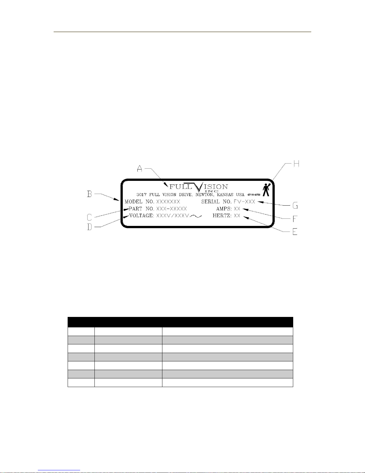
Serial Number
Every TRACKMASTER treadmill has a unique serial number for identification.
The serial number appears on the serial plate on the base of each unit.
Serial plate location and Identification
The serial plate is located on the right side rail of the treadmill.
Explanation of Serial Decal Information
Item Name Description
A Manufacture Full-Vision Inc.
B Model Number Identifies model of treadmill
C Part Number Manufacturers part number
D Voltage Specifies voltage of treadmill
E Hertz Specifies hertz of treadmill
F Amps Specifies amperage of treadmill
G Serial Number Manufacturers assigned serial number
2-2 FVX, TMX Series Service Manual August, 2006

TRACKMASTER
General Description
Intended Use
The FVX325, TMX425 series treadmill is for use only with pre-tested and
approved monitoring systems.
The emergency stop switch is intended for emergency situations where
immediately stopping the treadmill is required to deliver appropriate emergency
care to the patient. It is not intended for routinely stopping the treadmill.
Motor drive system
3
The 2hp, AC motor is controlled by a 2hp AC inverter drive, which connects
directly to the front roller with a drive belt. A 10lb flywheel attached to the
motor’s drive shaft keeps “footfall” variance to a minimum. An “adjustment
plate” between the motor and the treadmill motor pan allows for belt tension
adjustment using adjustment studs.
Elevation system
The elevation system uses a linear screw actuator to raise and lower the treadmill.
The elevation actuator attaches to the motor pan and elevation assembly.
The upper and lower limit switches are an integral part of the actuator, located on
top of the actuated under an access cover. This design allows easy access and
adjustment of the limit switches.
Electronic Assembly
The motor pan contains the power supply relay board and the inverter drive.
These can be accessed by removal of the hood assembly and can be replaced
individual.
August, 2006 FVX, TMX Series Service Manual 3-1
TRACKMASTER
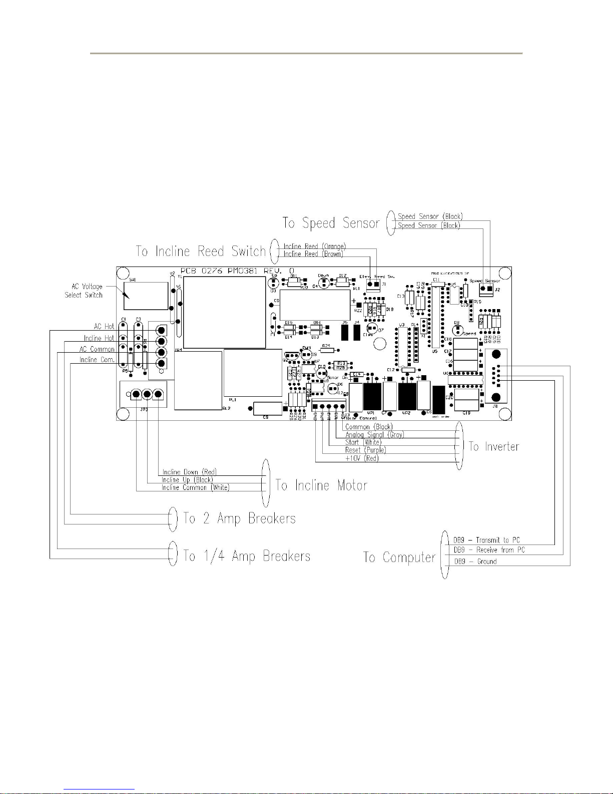
Power Supply Relay Board Detail
3-2 FVX, TMX Series Service Manual August, 2006
TRACKMASTER
Preparation for use
Safe handling guidelines
Lift the end of the bed assembly to a comfortable height, keeping knees bent and
backs straight as you lift.
Rotate the treadmill in the direction you want to go (the treadmill will pivot on its
wheels) and push forward.
When you have maneuvered the treadmill into its new location gently lower the end
of the bed assembly to the floor.
4
August, 2006 FVX, TMX Series Service Manual 4-1
TRACKMASTER
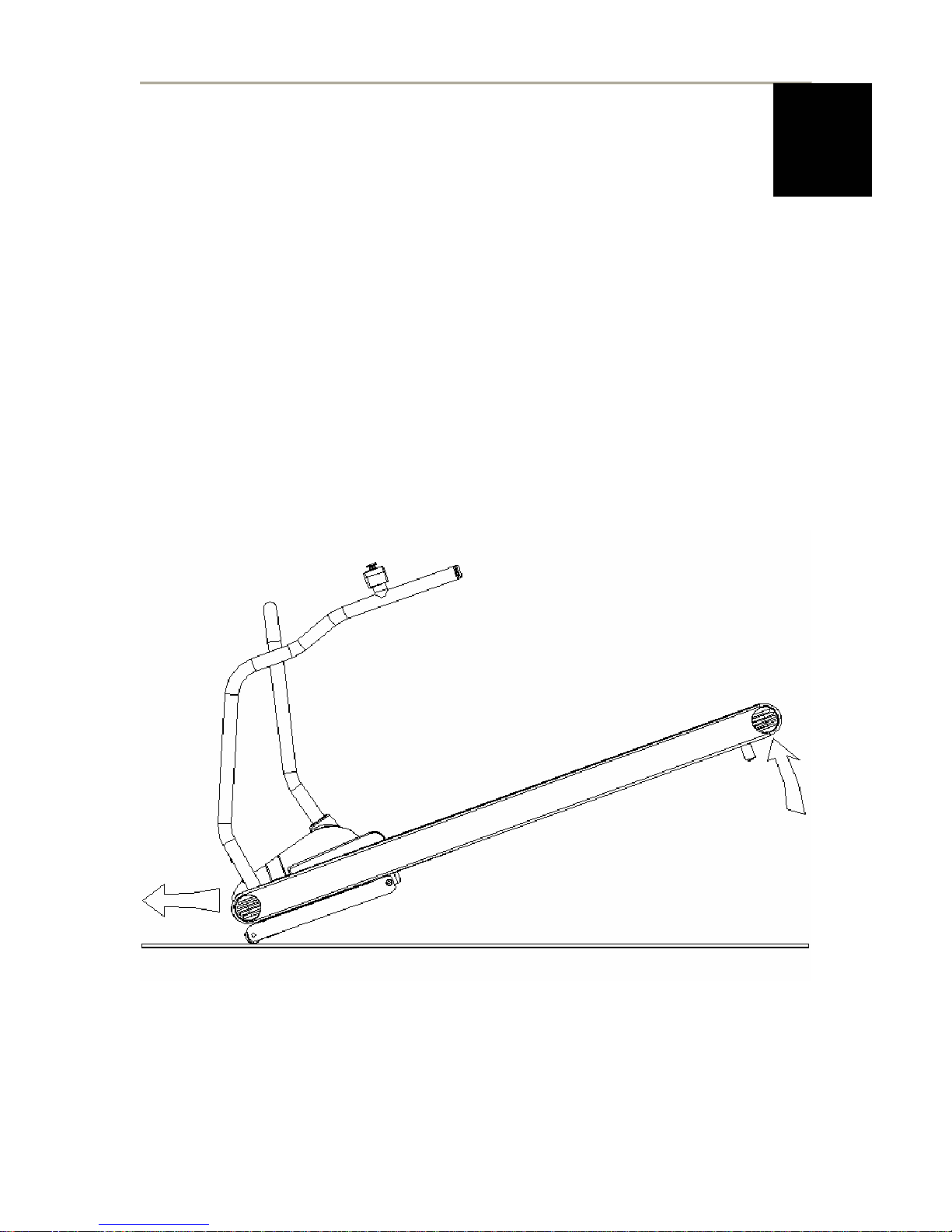
FVX325 Series Initial Setup and Assembly
FVX325 Series treadmills are shipped with handrail folded down for shipping.
Tools required for assembly
5/16 Allen wrench
1. Rotate handrail to up right position.
2. Start 2~3/8-16 Socket head cap screw into lower legs.
3. Start 2~3/8-16 Socket head cap screw into upper handrail.
4. At this point tighten all 8~3/8-16 socket head.
Check unit for proper operation
If unit has no power check ESB (Emergency Stop Button) to assure the button
is not pressed.
To check unit for proper operation, perform Test Plug Procedure ref chapter 4-5
4-2 FVX, TMX Series Service Manual August, 2006

TRACKMASTER
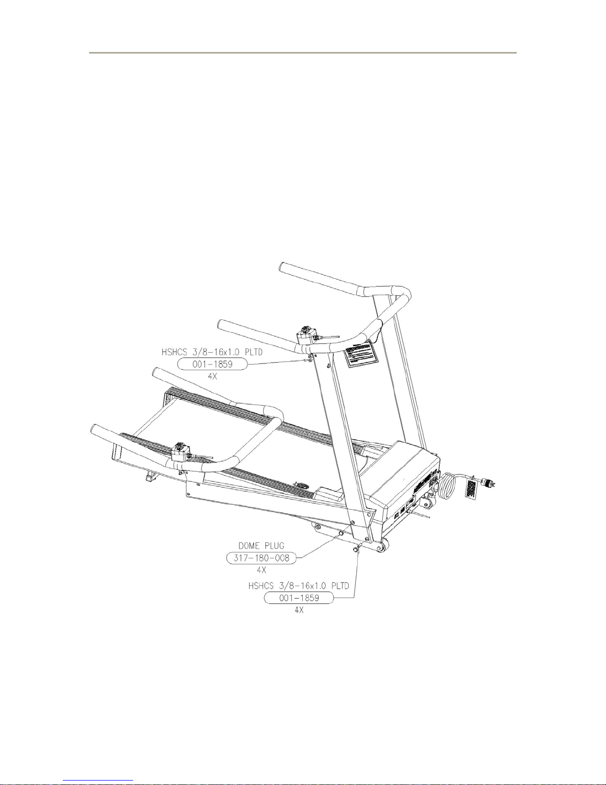
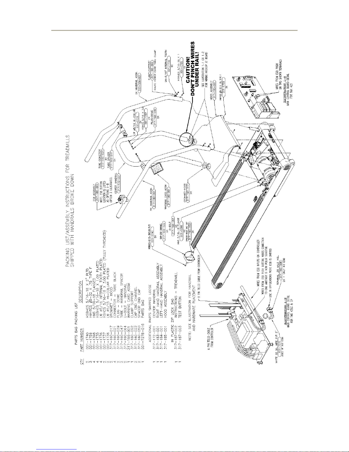
TMX425 Series Initial Setup and Assembly
Treadmills may be ordered broke down or fully assembled. If you have received one
broke down please follow the instructions below.
Tools required for assembly
1/4" Hex key
3/16” Hex key
1/4" Hex nut driver
1/2" wrench
1. Slide hood Grommets on to center rail (Approx. 2 ft. up), one each tube.
2. Next install U-bolts on to motor pan, place nuts on loosely, do not tighten, just to hold in
place
3. Slide hood on center rail and force up past Grommets to keep it from sliding down.
4. Route wire through U-bolt if wiring present on center rail.
5. Slide center rail down through U-bolts until rail slides into rubber base mounts.
CAUTION! Be sure that no wires are pinched when handrail is seated in lower
mounts or DAMAGE will occur!
6. ALL hardware should be left loose to aid easy assembly!
7. Install the outer rails by first routing wire through hole, provided your application has a
wire in the rail.
8. Slide the outer rail over the bracket and start the four button Head Bolts with washers into
base of handrail.
9. Add clamp to one bolt and route power cord with RS 232 cable thru it.
10. Install tube connectors with tube spacer between inner and outer rails and secure with
5/16 x 3” socket head bolt with lock washer.
After all hardware is in place tighten all bolts, U-bolts last. Be sure center handrail is
11.
down, by firmly applying pressure to it when tightening it.
12. Plug in wiring per illustration and lower cover.
13. Secure cover with three ¼” hex head self-tapping machine screw in front.
14.
Adjust brackets assuring Velcro makes contact at rear of the cover.
15. Slide Grommets down against the cover last.
Add Warning Card assembly with chain, and plastic dome plugs.
16.
17. Install End Caps and End Cap Spacer, Use a 3/16 Allen wrench to secure end caps (see
illustration).
August, 2006 FVX, TMX Series Service Manual 4-3
TRACKMASTER
Check unit for proper operation.
If unit has no power check ESB (Emergency Stop Button) to assure the button is not
pressed and wires are connected at board.
To check unit for proper operation, perform Test Plug Procedure ref chapter 4-5
4-4 FVX, TMX Series Service Manual August, 2006
TRACKMASTER
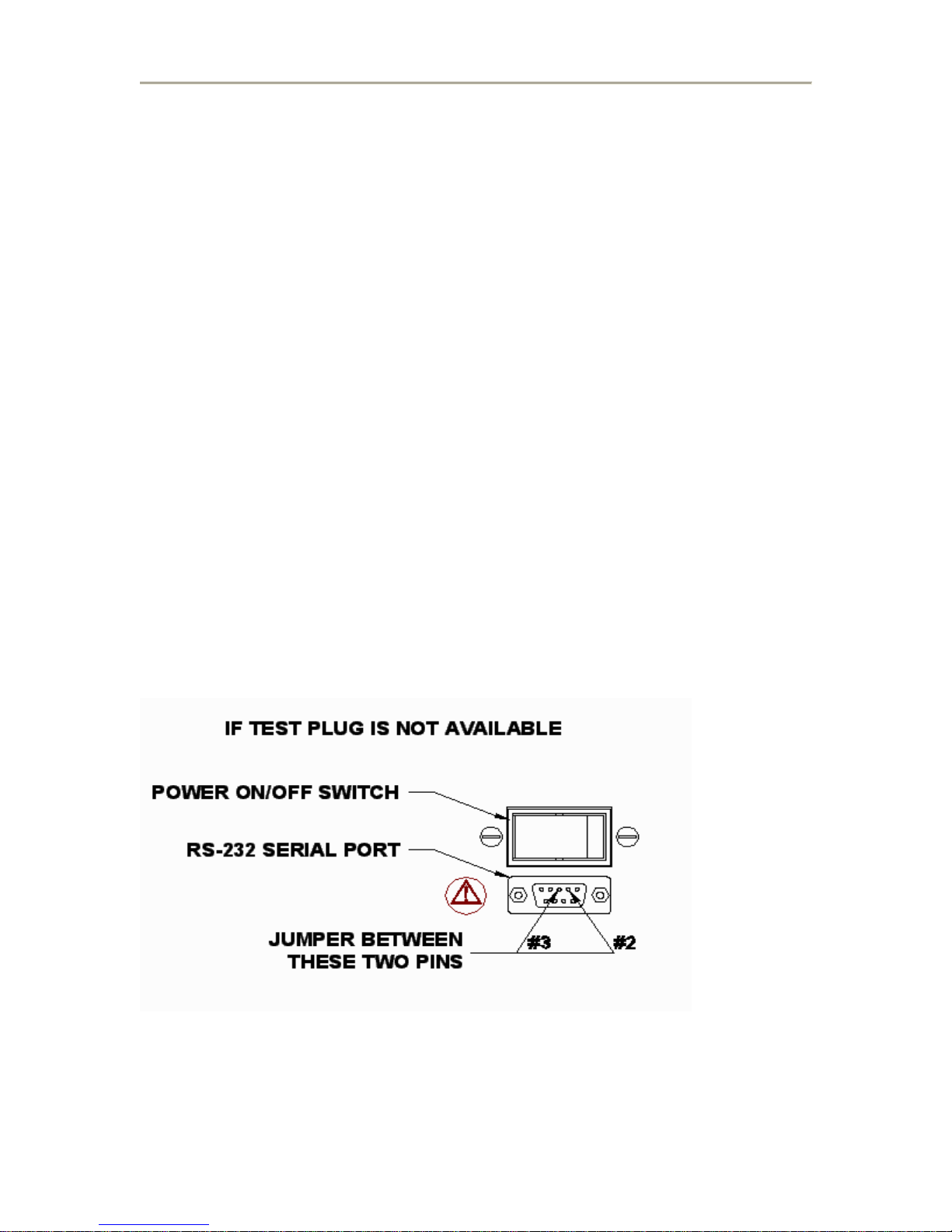
Test Plug Procedure (RS232 Units Only)
1. Turn the power “OFF” at the treadmill.
2. Disconnect RS232 interface cable from the treadmill and plug in the test
connector.
3. Hold the button down on the test connector and turn treadmill power “ON”.
Continue holding until treadmill begins to elevate.
4. Once this is initiated, with each push of the button the treadmill should elevate
5% grade.
5. When the treadmill reaches 20% elevation the next push of the button will start
the treadmill running belt.
6. With each push of the button the treadmill will increase speed by 2.5 miles per
hour.
7. Once the treadmill reaches 10 mph, each push of the button will bring the speed
down 2.5 miles per hour and simultaneously lower the elevation level by 5%
increments.
8. When minimum speed and elevation is reached the next press of the button will
cause the treadmill running belt to stop.
9. Remove the test connector.
10. Reconnect the RS232 interface cable.
Once treadmill is in place and operational, the belt tracking should be checked and adjusted if
necessary.
August, 2006 FVX, TMX Series Service Manual 4-5
TRACKMASTER
Procedure for Belt Tracking and Alignment
Tools Required
1/4-in. Allen wrench
Running Belt Adjustment
CAUTION: Because this adjustment is not covered under your
warranty, it is important that you review these instructions
thoroughly before proceeding.
The TRACKMASTER® patented MasterTrack® Belt Tracking System significantly
reduces the need to adjust the belt on your TRACKMASTER® treadmill. However,
when you operate your treadmill for the first time, you may need to adjust the tracking of
the belt to conform to your floor. You may also need to adjust the tracking if you move
the machine to another location. Your running belt should remain centered, although a
slight amount of movement to the left or right is normal during use. Do not allow the
running belt to travel all the way to either side.
To adjust the belt tracking, do the following:
1. Turn the treadmill’s power switch to ON.
CAUTION: Do not stand on the running belt when starting the
treadmill. You could fall, causing serious injury.
2. Increase the speed to 3 mph.
3. Observe the left side of the running belt as it travels over the rear roller. If the
belt runs to the right side of the roller, turn the right bolt one-quarter turn
clockwise, and turn the left bolt one-eighth turn counterclockwise.
Note: When tightening one side of the belt, always loosen the opposite
side one-half as much. This procedure provides finer control, with a
smaller impact on belt tension.
4. Check the belt after 2 minutes, with the treadmill running at approximately 7
mph. If the belt does not correct itself, continue with slight turns until the belt is
in the center of the rear roller. If the belt runs toward the left, use the left
adjustment.
4-6 FVX, TMX Series Service Manual August, 2006
TRACKMASTER
Note: Uneven floors accelerate belt misalignment. This situation may
require larger and more frequent adjustments to prevent belt damage.
Note: When adjusting belt misalignments make sure V-Guide is not riding
up on the front and rear roller.
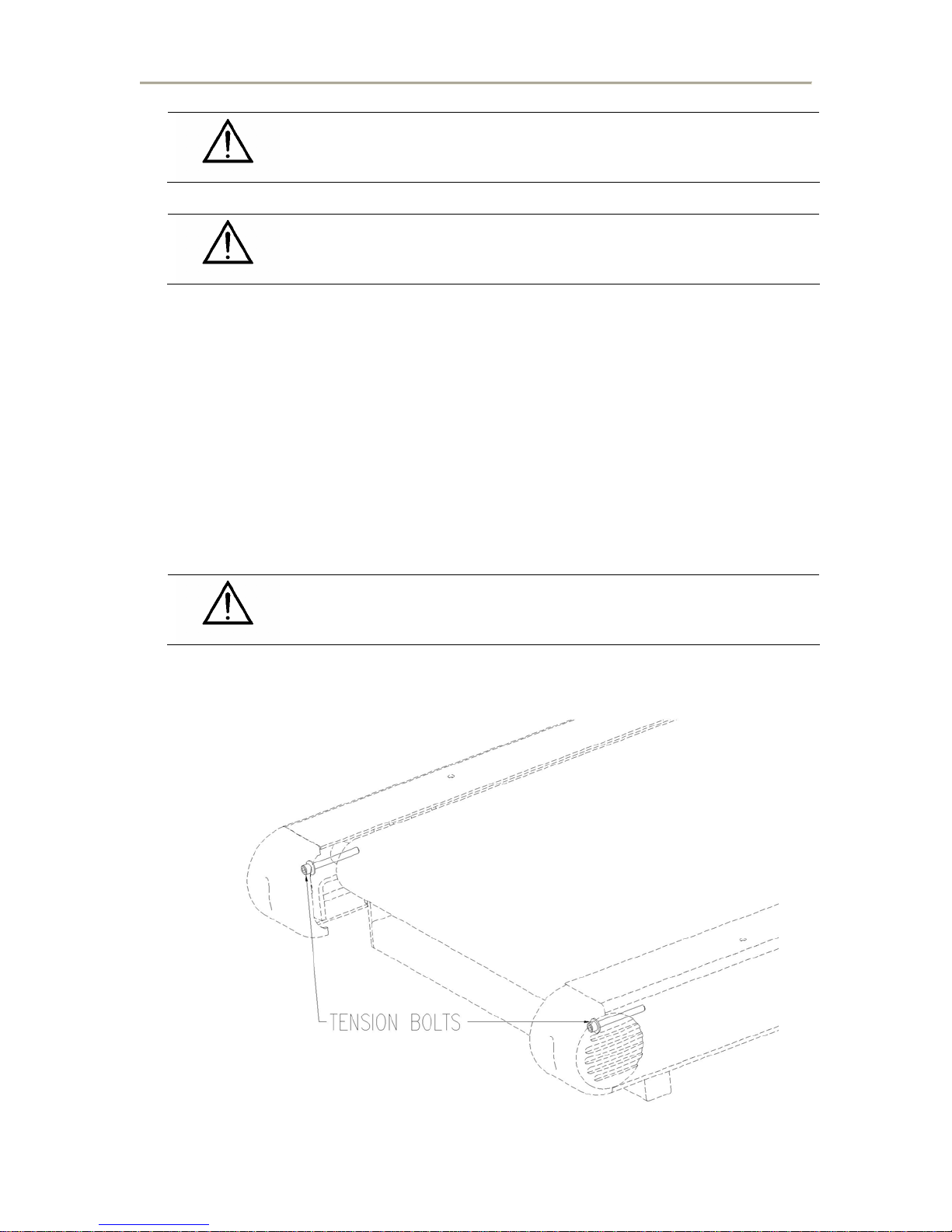
Belt Tension Adjustment
The running belt may stretch and loosen with regular use. This looseness is noticeable when
the belt tends to hesitate or stick. If the belt is loose and slipping, see illustration below.
1. Turn the treadmill’s power switch to ON.
2. Start treadmill and increase to 1 mph
3. Start walking on the treadmill, grab handrail and apply pressure with your foot to
create resistance on running belt.
4. If running belt start slipping on front drive roller, tighten both tension bolts ½ turn
(Clockwise).
5. Repeat steps 2 thru 4 until running belt stop slipping.
Note: When running belt is to tight the edge of belt will curl causing
premature running belt failure.
August, 2006 FVX, TMX Series Service Manual 4-7
TRACKMASTER
Drive Belt Tension Adjustment
The drive belt may stretch and loosen with regular use. This looseness is noticeable when you
may here a flapping noise. If the drive belt is loose, see illustration below.
1. Turn the treadmill’s power switch to OFF.
2. Press down on drive belt in between motor and front roller with approximately 5 lbs
of force.
3. The drive belt should deflect approximately ¼” to 3/8”.
4. If deflection is more that 3/8”; see Motor Pan Assembly Chapter 13 for detail
drawing.
5. Loosen 4 Motor mounting nuts on underside of treadmill.
6. Adjust Motor tension adjustment. FVX Series is located outside front; TMX Series is
located inside motor pan.
7. Turn adjustment tension nut equally to assure drive belt alignment.
8. Make small adjustments until drive belt deflection approximately ¼” to 3/8”
Note: When drive belt is over tensioned, the belt tension will cause motor
noise. This could result in premature motor life failure.
4-8 FVX, TMX Series Service Manual August, 2006
TRACKMASTER
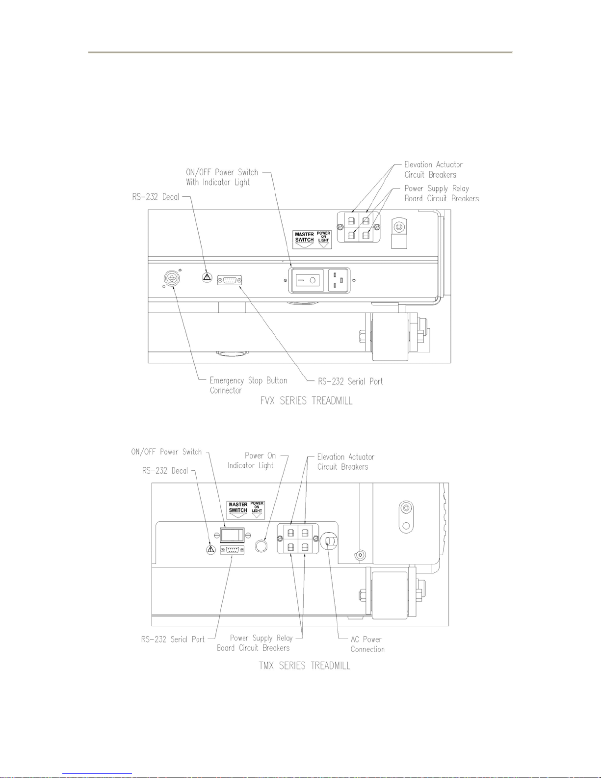
Connector and switch locations
The illustration below shows the various connectors and switches located on the base of
the treadmill.
August, 2006 FVX, TMX Series Service Manual 4-9
TRACKMASTER
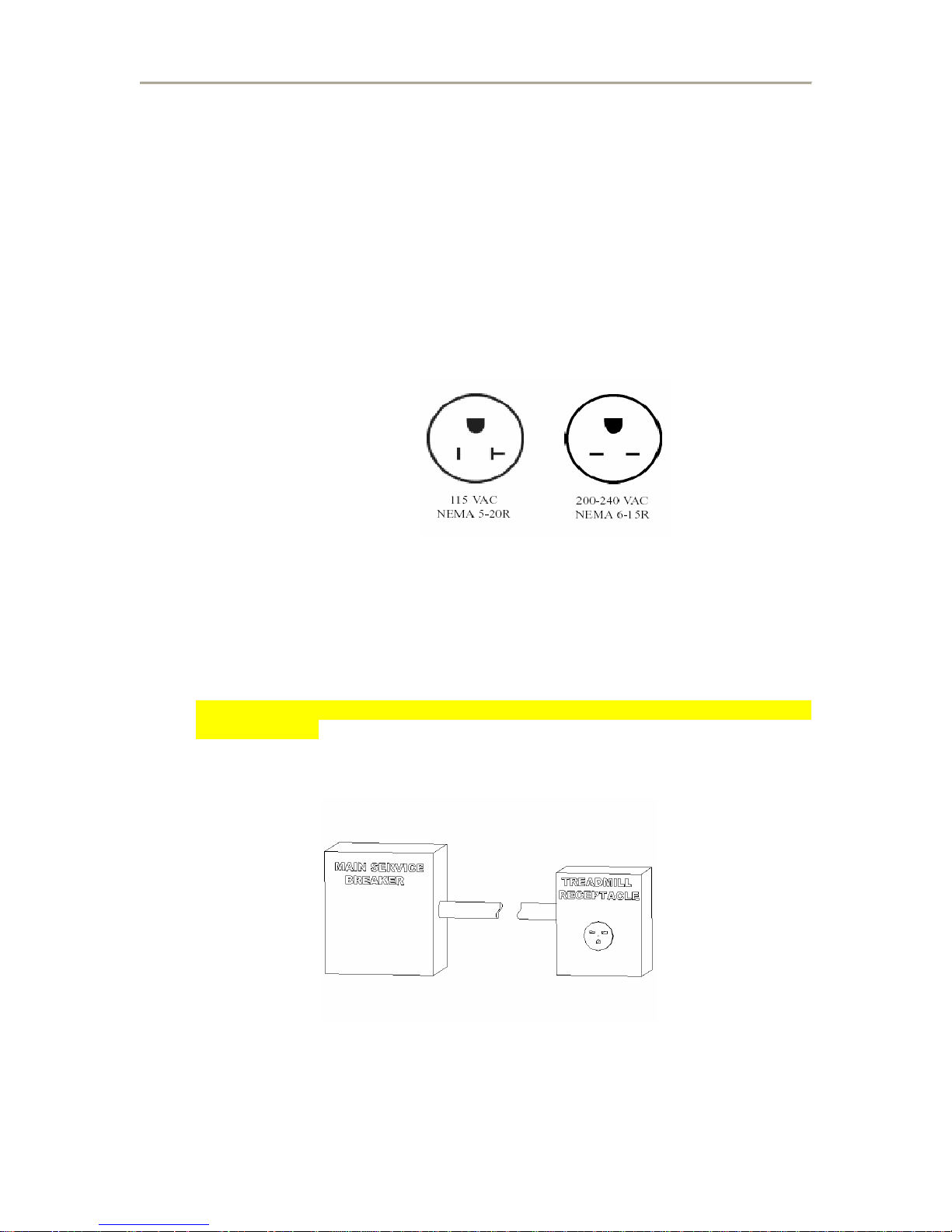
Power requirements
Grounding Instructions
This product is equipped with a three-wire ground-type plug. The plug will fit into only a
grounding-type outlet. This is a safety feature – do not disable the plug’s third (grounding)
pin with an adapter! Contact a qualified electrician if you are either (1) unable to insert
the plug into your outlet, or (2) uncertain that the outlet is grounded and meets local codes.
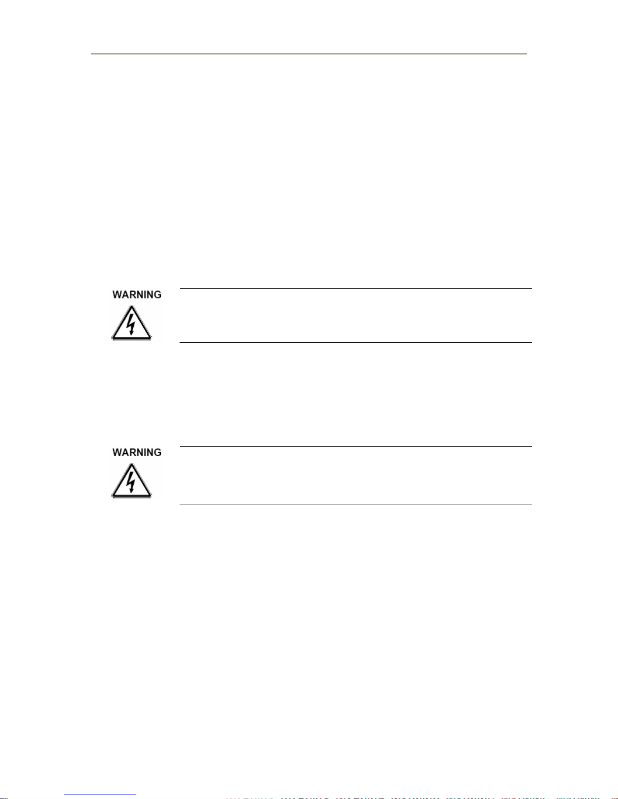
Dedicated circuit
A dedicated circuit is a power outlet reserved for the exclusive use of your treadmill.
This requires a power line to be routed from the main breaker box or sub-panel to the
power outlet for the treadmill. The outlet should not be shared with any other
components.
NOTE: In 110V applications, a 20 AMP High Magnetic type circuit breaker is
required for use. This is to Prevent the breaker from being thrown by a temporary high
current draws when the treadmill is switched on. For Square D service box use Part
number Q0120HM. For GE Service Box use Part Number THQL1120HM. Contact your
distributor for further information regarding this type of breaker.
4-10 FVX, TMX Series Service Manual August, 2006
TRACKMASTER
Operating and Storage Condition Recommendations
Operating Temperature Range: 0 to +40 deg. C (+32 to +105 deg. F).
Storage Temperature Range: -20 to +70 deg. C (-4 to +158 deg. F).
Operating and Storage Relative Humidity Range: 8% - 80%, non-condensing.
Altitude: -50 to 10,000 feet.
Installation After Long Period of Storage
Storage exceeding three years, Contact Factory Immediately prior to plugging in
treadmill. Failure to do so will cause inverter drive to FAIL!
If input power has not been applied to the drive for a period of time exceeding three years
(due to storage etc), the electrolytic DC bus capacitors within the drive can change internally,
resulting in excessive leakage current. This can result in premature failure of the capacitors if
the drive is operated after such a long period of inactivity or storage.
Severe damage to the inverter drive can result if it is operated after a long period of
storage or inactivity without reforming the DC bus capacitors! Contact the factory
for proper instruction.
August, 2006 FVX, TMX Series Service Manual 4-11
 Loading...