

trackit VT10 Installation Instructions Manual

_____________________________________________________________________________________
-1-
TrackIt Limited – V 7.5 April 2013
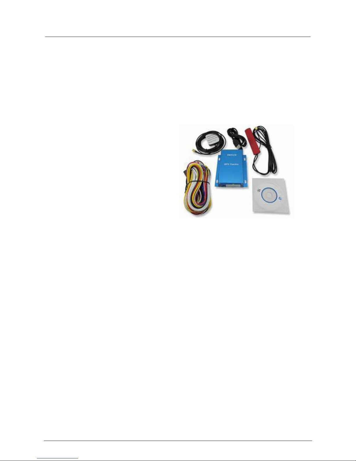
VT10
Vehicle GPS Tracker
Installation Instructions
V7.5

-2- TrackIt Limited – V 7.5 April 2013

_____________________________________________________________________________________
-3-
TrackIt Limited – V 7.5 April 2013
VT10 Vehicle Tracker
IMPORTANT – READ FIRST:
The purpose of this document is to establish the minimum standard required when installing TrackIt
GPS devices in vehicles. The intention is to provide technical guidelines for cabling, connectors and
componentry used in all installations to obtain a consistently high quality of workmanship across fleets
nationwide.
1. A simcard has already been installed in the device.
2. Cut and dispose of any excess wiring in supply loom, staggering the lengths so as not to
short against each other, the loom should then be insulated using insulation tape.
3. It is recommended to solder all wiring joints rather than crimping.
4. The earth (black wire) needs to be secured directly to the vehicle body (ground) to
eliminate any feedback or interference with any of the vehicle’s other circuits.
MAIN UNIT POWER SUPPLY
5. When installing the GPS TrackIt device, power supply to the unit should be taken from an
uninterrupted battery power supply between 9-36V. 5A fuses must be added to the
supply line (if not already included). The two red power supply wires can be spliced
together as one wire. Power supply cannot be drawn from high fluctuating current
circuits, particularly lighting circuits and hazard connections etc. Under no circumstances
should power be taken from SRS or ABS systems.
IGNITION SWITCH SUPPLY
6. The ignition switch input on the TrackIt device must be fused and taken from a reliable
supply. For example, directly from the vehicle’s ignition switch or fuse box supply. It is not
recommended to piggy-back an existing system such as a radio, heater, aircon etc as these
circuits may backfeed (unless you use ferrite sleeves threaded through the main power
loom) and create a false ignition alarm signal.
MAIN UNIT MOUNTING
7. When mounting the main unit the following points should be taken into consideration.
The unit should be:
Positioned as close to the power source as possible thereby eliminating the need to
run long lengths of wiring which may act as an antenna and cause electrical noise
through the stereo.
Out of sight and not in a position where it can be easily tampered with.
Mounted securely to avoid vehicle shocks and vibrations.
In a dry area (ie not in the footwell which may become damp in wet weather)
ANTENNA MOUNTING (GPS)
8. When mounting the GPS antenna the following points should be taken into consideration.
The GPS antenna should be:
Dome side up. Make sure GPS gets fix (blue LED flashes 0.1 second on and 2.9
seconds off). Blue LED stays 1 second on and 2 seconds off (can’t get GPS fix) after
the unit is turned on.
It must not have any metal covering the antenna or directly above it (pillars, roof,

-4- TrackIt Limited – V 7.5 April 2013
dashboard brackets etc).
Located as high as possible without being obvious.
Kept away from AM/FM radio antenna. To avoid interference do not run the
GPS/GSM antenna wiring along or over the AM/FM radio.
Do not tie antennas with power loom – if this cannot be avoided, thread 1 x ferrite
sleeve through red power loom. The ferrite sleeve works on eliminating
interference especially with older radios.
ANTENNA MOUNTING (GSM)
9. When mounting the GSM antenna the following points should be taken into consideration.
The GSM antenna should be:
Ideally mounted at the base of the windscreen for maximum GSM reception.
However, if an installation is covert and must be hidden the following should be
taken into consideration:
Make sure the unit is already connected to GSM network (Green LED flashes 0.1
second on and 2.9 seconds off). Green LED stays 1 second on and 2 seconds off
(can’t get GSM signal) after the unit is turned on.
It must not have any metal covering the antenna or directly above it (pillars, roof,
dashboard brackets etc).
Located as high as possible without being obvious.
Kept away from AM/FM radio antenna to avoid interference.
Do not tie antennas with power loom – if this cannot be avoided, thread 1 x ferrite
sleeve through red power loom. The ferrite sleeve works on eliminating
interference especially with older radios.
INPUTS/OUTPUTS
10. The inputs/outputs on the device MUST comply with the following standards:
INPUT 1: SOS button (already wired)
INPUT 2: Crash sensor (optional)
INPUT 3: Car Alarm (optional)
INPUT 4: Ignition (MANDATORY)
INPUT 5: Door Sensor (optional)
OUTPUT 1: If a relay switch is being installed it MUST be wired to thisoutput to
immobilize the vehicle.
Once the device has been installed, please call (0508) TRACKIT and quote the D: number recorded on
box. We can then complete the setup and confirm the unit is functioning correctly.
PLEASE NOTE: (AND ADVISE YOUR CUSTOMERS)
This device will draw a small amount of current which over a period of time will discharge your battery
if the vehicle has prolonged periods of not being used. We strongly recommend that you attach a trickle
charger to your vehicle whilst it is in storage to prevent your battery from being drained.
-5- TrackIt Limited – V 7.5 April 2013
1 . Product Overview
The VT10 is a GPS/GPRS based tracking device specially developed and designed for vehicle real-time tracking
and fleet management. VT10 has inbuilt GPS module to obtain accurate position data and utilizes its GSM
capability to send the position data to a specified mobile phone or server base for tracking and fleet
management. With internal memory, VT10 can store GPS coordinates when there is no GPRS connection or at
a specified interval requested by the user. One optional feature of VT10 is that a microphone can be linked
out to be hidden somewhere inside the vehicle for listening to the cabin
.
VT10 has the following functions and features:
SMS and GPRS TCP/UDP Communication
AGPS (with GSM Base Station ID)
Track on Demand
Track by Time Interval
GSM Blind Area Memory
Internal Memory for Logging
Inbuilt Motion Sensor for Power Saving
SOS Panic Button
Movement Alarm
Geo-fencing Control
Low Battery Alarm
Speeding Alarm
GPS Blind Area Alarm (in/out)
Power-cut Alarm
Engine Cut (Stop Engine)
I/O: 5 digital inputs (3 negative and 2 positive)
 Loading...