

TrackingTheWorld WorldTracker AVL User Manual

www.trackingtheworld.com
TrackingTheWorld®
WorldTracker AVL
Manual
Confidential and Proprietary Information - © 2009 TrackingTheWorld
Do not duplicate without express permission from TrackingTheWorld

WorldTracker AVL
WorldTracker AVL Manual
Index
1. Basic first startup and testing Page 2-11
2. Configuration and setup Page 12-26
3. SMS commands accepted by the tracking unit Page 28-34
4. Uploading the Operating System to the AVL Page 37-39
5. Upload operating system, configuration file or Page 40-43
GPS location Table over the air using GPRS
6. Geo Fencing and PARK Fencing Page 44-47
7. Messages send by AVL Page 48-55
8. Serial port data sending using the GSM Modem Page 56
9. Basic testing and problem solving Page 57
10. GPRS testing Page 58
11. AT COMMANDS for GPRS support Page 59-74
12. Receiving and sending GPRS data Page 75
13. AVL Connections Page 76-84
14. Installation Page 85-87
15. Technical Specification Page 88-92
Installing SIM card with different PIN NUMBER Page 27
Unit activation and sleep Mode Page 35
Software and hardware lock-ups Page 35-36
Priority of Messages VE Page 56
FCC Statement Page 93
- 1 -
Basic first startup and testing
The AVL has been designed to make installation, testing and configuration simple. For vehicle
installation and testing for correct working after installation we recommend the installer to use a Notebook or
PDA with serial port and serial communication software installed.
On a windows based computer you will be able to use ‘Hyperterminal’ (free with Windows). For PDA or
Pocket PC you can use several communication programs that can be downloaded from the internet like
‘ZTERM for Pocket PC’ (http://www.coolstf.com/ztermppc).
Before the unit is installed, we recommend configuring the unit functions and setup using the AVL setup
configuration program. The AVL has many functions that will allow the unit to operate for different
user applications including security and fleet management.
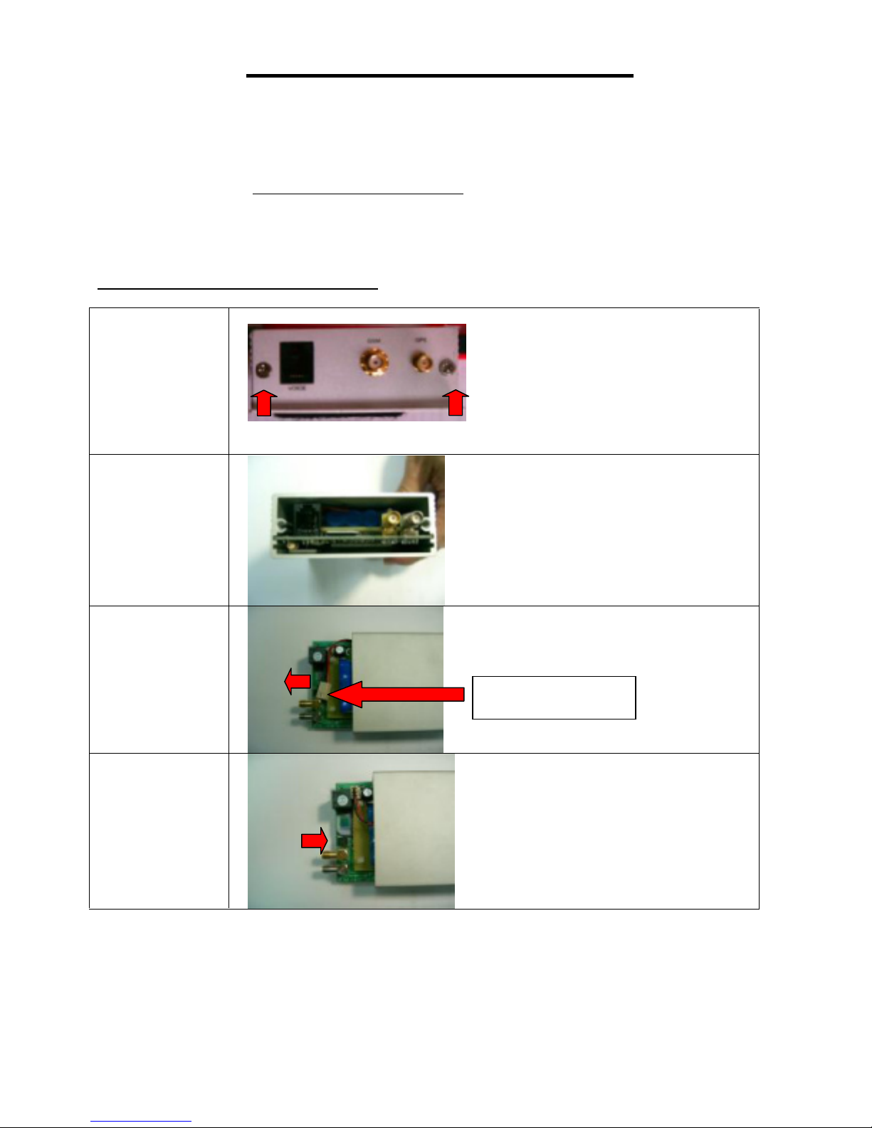
Sim card and back up battery Installation
Please undo
those 2 screws
Take out the
side board
Slide out the PCB
(push from other
side)
Insert the SIM card
Battery connector
- 2 -
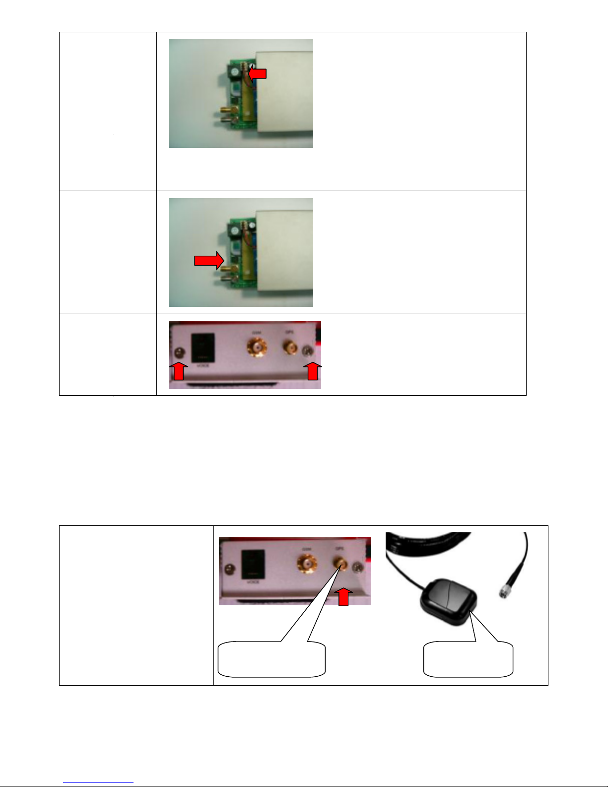
Plug in the back up
battery connector
Note:
Back up battery
connector need to
be plugged in after
SIM card (*)
inserted.
The unit will still
operate without
back up battery
Push back the PCB
Be careful for the
battery connector
Screw back all
screws
Note: If you want to change another Sim card, please unplug the back up battery connector first, change the
sim Card then plug back the back up battery connector.
(*) Please disable pin code or set pin code to 0000 (4 * zero).
Connect the I/O cable com port and antennas
Connect GPS antenna with the
right hand connector
GPS antennaGPS connector
- 3 -
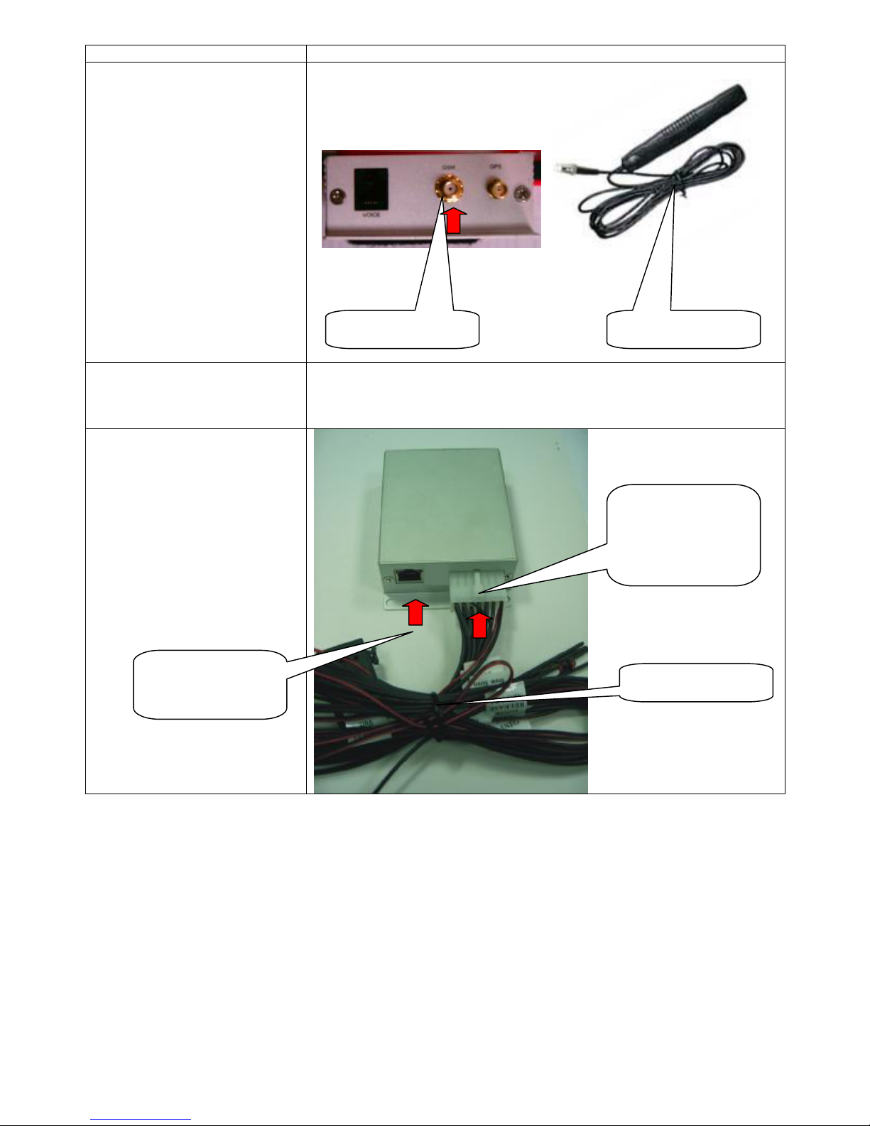
Connect GSM antenna
(middle connector)
Connect up I/O cable, (I/O cable
included main power input). The
cable has labels that shows
function.
Connect RS232 cable for
communicate with PC
GSM antennaGSM connector
Left port (RJ45,
UTP plug Type)
I/O cable connector,
this side must face
up
I/O cable
- 4 -

Getting started, use Hyper Terminal to test AVL
Step 1
Connect AVL with your PC using com port
To test the AVL after installation the External Serial Port Connector (standard 9 pin
serial plug -DB9) of the unit should be connected either directly or via an extension
cable to the serial port of a PC running Windows.
Step 2
Using Hyper Terminal
The PC will need to be running HYPERTERMINAL, which is a free program that
comes with Windows.
If HyperTerminal is not currently installed on the PC you will need to do the following:
1. Go to Start/Settings/Control Panel.
2. Go to Add/Remove Programs/Windows Setup Tab. This will bring up a list of
components that can be installed.
3. Put a tick in the Communications Check box and double click. This will bring up a
list of components that can be installed. Put a tick in the box next to HyperTerminal.
You may need to insert your Windows Disk to install the program.
4. You may need to restart your computer after the program has installed.
5. Remember to connect the serial port on the unit to the serial port on the PC.
Once HyperTerminal is installed and running you will need to set the Baud Rate to
9600 Baud and set the Com Port (usually Com 1 on a laptop).
We strongly recommend that the unit be tested using a computer as this allows all
options to be tested quickly and easily. The operating system/or a new or modified
operating system can only be uploaded (in x-modem format) if the unit is connected
to a serial port on a computer.
Step 3
Power up the unit. There are 2 leds above the RJ45 MULTI port connector. The green led
will be on or will start flashing after power on (GPS output status led). The yellow led will
flash when the unit is testing the GSM modem and if SIM card is installed. This led must
be off during normal working.
Once the unit is connected to the serial port and has been connected to the +12 volt
and Earth connections, the following screen will appear in HyperTerminal:
- 5 -
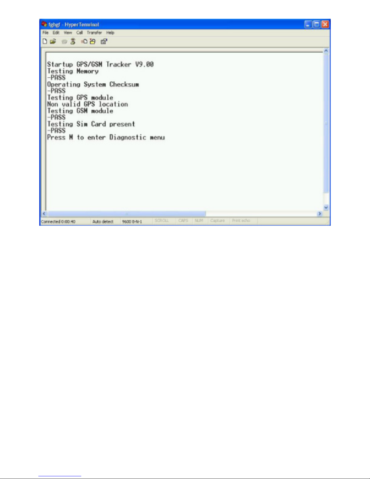
Startup AVL XXXX
Testing Memory
-PASS
Operating System Checksum
-PASS
Testing GPS module
Non-valid GPS location
Testing GSM module
-PASS
Testing SIM Card
-PASS
Press M to enter Diagnostic menu
If the unit FAILS any of the above tests the distributor should be contracted for a
replacement. Except the Operating System Checksum test where no Operating
System is installed yet.
If the unit goes into a loop from Testing GPS module, it could be because of low
voltage input. Please make sure the input voltage input is +6V DC or More.
Step 6
Get into Diagnostic Menu
Pressing the M key will then take you to the Diagnostic Main Menu.
- 6 -
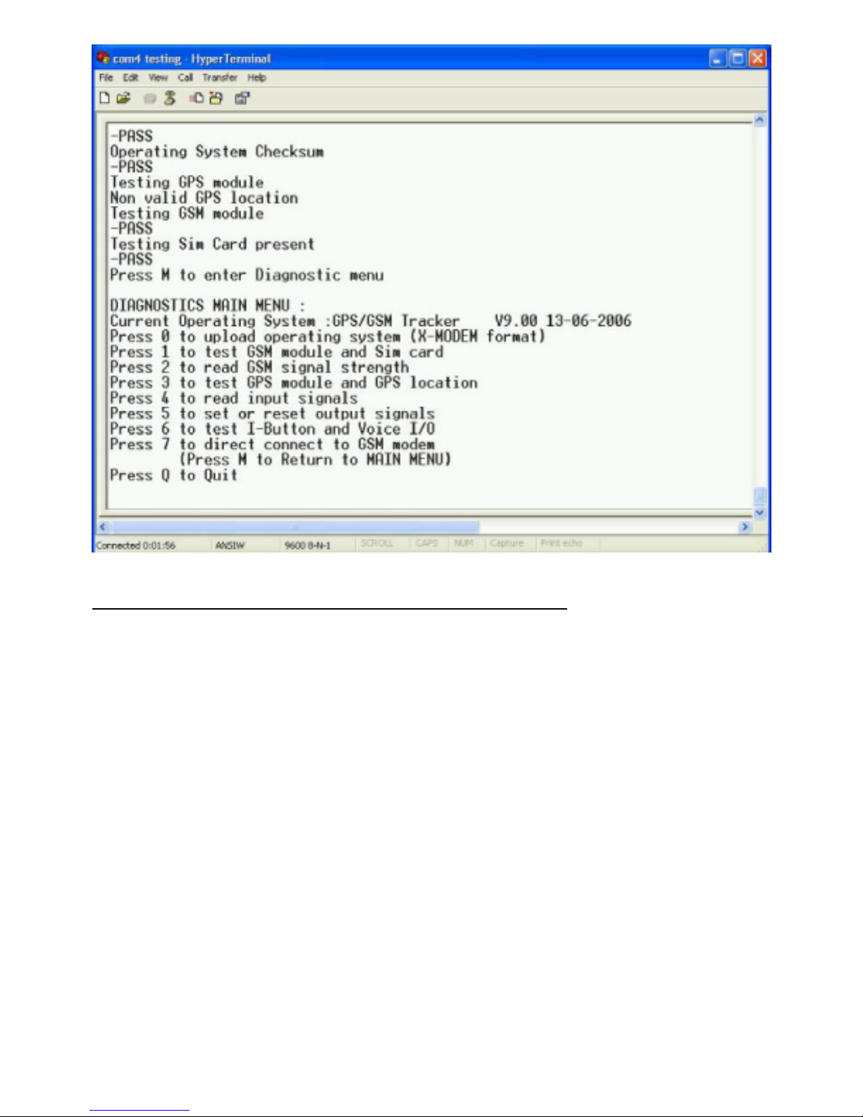
The following are the options in the Diagnostic Main Menu:
DIAGNOSTICS MAIN MENU:
Current Operating System: GPS/GSM Tracker V9.00 13-06-2006
Press 0 to upload operating system (X-MODEM format)
Press 1 to test GSM module and Sim card
Press 2 to read GSM signal strength
Press 3 to test GPS module and GPS location
Press 4 to read input signals
Press 5 to set or reset output signals
Press 6 to test I-Button and Voice I/O
Press 7 to direct connect to GSM modem
(Press M to Return to MAIN MENU)
Press Q to Quit
** Please note options in the menu can be different from your current version.
Test 1 Test GSM module and SIM card on board
This will test if the tracking unit can communicate with the GSM modem and that a SIM
card is installed. The tracking unit will not work if there is no SIM card installed.
After testing you will return to the Diagnostic Main Menu.
Test 2 Test GSM signal Strength
- 7 -

The aerial/aerials may need to be adjusted for optimum signal strength. The
signal strength will be shown in HyperTerminal as:
Low
Medium or
High
Test 3 Test GPS module and GPS location
The following will appear on screen in HyperTerminal:
Testing GPS module
Non-valid GPS location
Press M to Return to MAIN MENU
Non-valid GPS location
Press M to Return to MAIN MENU
Non-valid GPS location
The GPS location will always be either:
Valid or
Non-valid
It may take several minutes for the GPS receiver to find the satellites and
return a valid location. Remember the GPS will only find a satellite if the
car is outside and the aerial has not been installed in a location in the
vehicle where the signal is blocked by metal.
Test 4 Test all the inputs
To read the Input Signals press 4 in HyperTerminal.
The unit will display current input signals as Activated or not activated.
Remember not all Input Signals can or will be connected up at this time.
This test will check the Input Signals to see if they are Activated or Not
Activated. You will need to activate the alarm for the input to be activated
(turn on with remote and open car door). You will need to activate GEO (PARK)
fencing / press the Panic Button for them to be activated.
** Please note: AUX input 3 neg is the analog input. Care must be taken to insure that the
input voltage on this pin is between 0 and +3.3Volt (Max). Any higher voltage may damage
the tracking unit or the onboard fuse on this input.
Pressing M will return you to the Diagnostic Main Menu when you are finished.
Test 5 Test all the outputs
To set or reset the Output Signals press 5 in HyperTerminal.
SET OR RESET OUTPUT SIGNALS MENU:
Press 1 to enable alarm
Press 2 to disable alarm
Press 3 to enable SOS
Press 4 to disable SOS
Press 5 to open car doors
Press 6 to flash GEO (PARK) fencing LED
Press 7 to disable GEO (PARK) fencing LED
Press M to Return to MAIN MENU
Press 1 and the alarm will be enabled as shown in HyperTerminal:
- Alarm Enabled
You will then return to the Set or Reset Output Signals Menu.
Press 2 and the alarm will be disabled:
- Alarm Disabled
- 8 -

You will then return to the Set or Reset Output Signals Menu.
Please follow the same procedure for the rest of the Output Signals.
When you test the SOS Output (Press 3) the brake lights will flash the
SOS signal and pressing 4 will disable the SOS signal. Only for testing
purposes*. If you lock the car doors, the doors will open when you test
the Open Car Doors Output (Press 5). Pressing 6 will flash the GEO(PARK)
fencing LED if one is connected and pressing 7 will disable the GEO (PARK)
fencing LED. Only for testing purposes*.
Remember to reset all outputs when you are finished testing.
*The Outputs will only be disabled (reset) for testing purposes while the
unit is in Diagnostic mode, they will still work if they are connected when
the unit returns to normal operation.
Pressing M at anytime will return you to the Diagnostic Main Menu:
Test 6 to test I-Button and Voice I/O
This test will allow you to test the I-Button and the Voice I/O.
I-Button AND VOICE I/O MENU :
Press 1 to READ I-Button
Press 2 to TEST Voice I/O
Press M to Return to MAIN MENU
Press 1 to Read I-Button
Press 2 to test Voice I/O
Test 7 direct connect to GSM modem
This test will allow you to test communication using AT commands between your computer
and the GSM modem.
The AT command ‘AT comstop’ <enter> or if no command has been send to the modem
for more then 60 seconds the direct modem connection test will end.
For GPRS we recommend you do manual test first to test if your GPRS setup is correct.
(See GPRS section for information about the GPRS Testing).
Press Q to exit!!
By pressing Q you will exit the Diagnostic Main Menu and return the unit to
normal operation. If you do not press Q or any other option within 10 minutes the
unit will return to normal operation.
The unit will display the GSM Modem information and IMEI number directly after you
Quit the Diagnostic Main Menu.
To return from normal operation to the Diagnostic Main Menu press X (or x).
Keep pressing X until the Diagnostic Main Menu appears. Please note that this
can take several seconds or more if the AVL is processing any alarm conditions
or messages!
Please always press “Q” after finish tests to exit diagnostic menu.
- 9 -
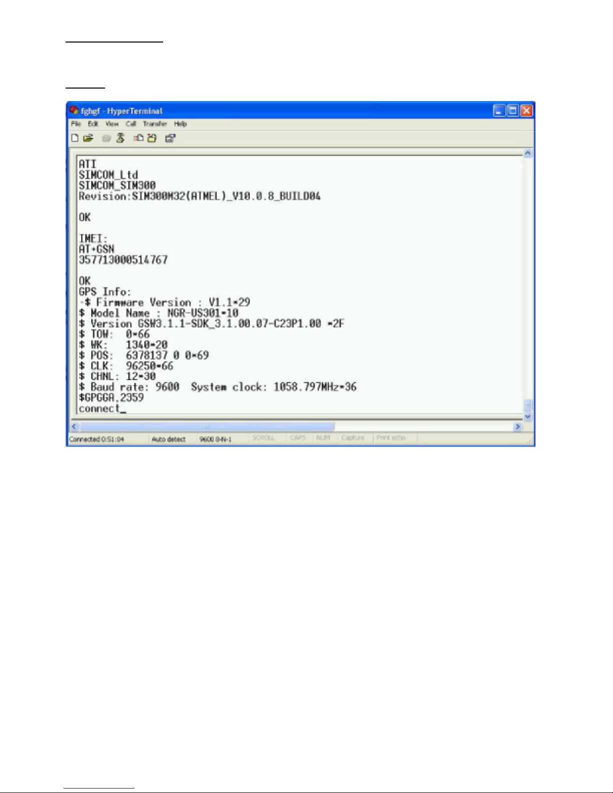
Modem information:
When you quit the ‘DIAGNOSTICS MAIN MENU:’ the tracking unit will report information about your GSM
modem:
Sample:
When the tracking unit is in normal operating mode the tracking unit requires the four-digit
password code (can be configured in the GPS Tracking configuration menu. Default is
‘1234') to return to Diagnostic mode after it receives the 'X' or 'x' command from
the serial port.
The password must be entered after the tracking unit sends the 'OK0' or 'OK1' command.
The correct password must be followed by <CR> (ENTER) to confirm password entered.
You must enter the correct password within 8 seconds or the tracking unit will return to
normal operating mode.
When in ‘Normal’ running mode the serial data communication between the GSM modem
and the CPU is directly send to the serial port. This allows the user to monitor or capture
the data.
Problems related to communication errors can also be easy detected.
- 10 -
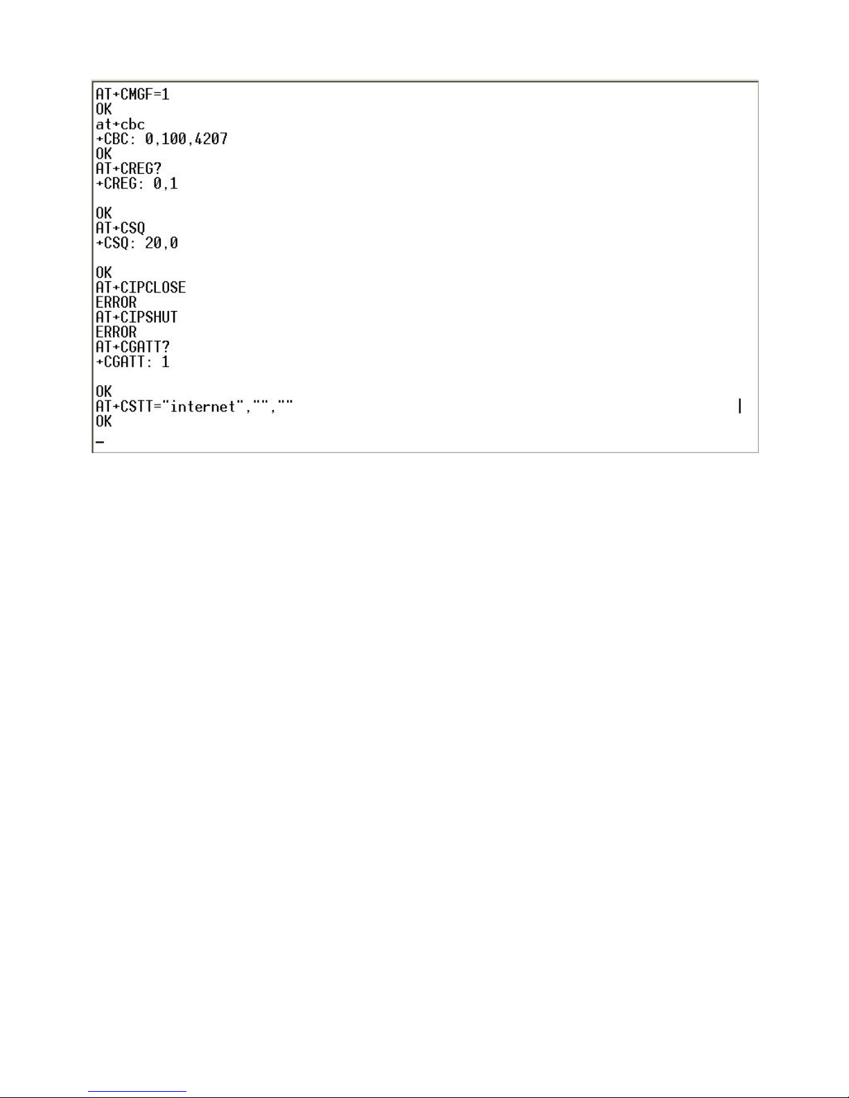
Sample data that will be shown when connected to the serial port.
- 11 -
Configuration and setup :
When the tracking unit powers up it will enter the ‘Diagnostic menu’ first. If no key is pressed for 30 seconds
the unit will enter normal operating mode.
Please note : The ‘AVL-setup.exe’ program can only access the tracking unit if the unit is working in
normal operating mode.
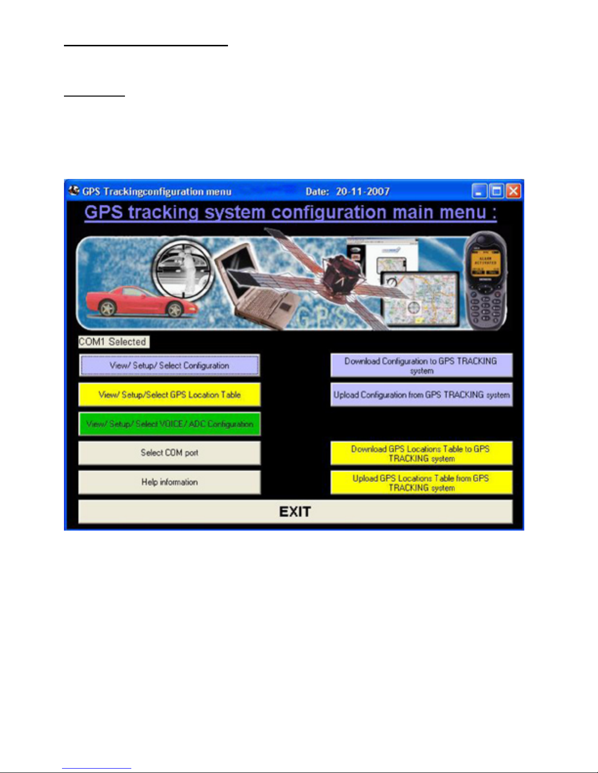
Start up the file AVL-setup.exe
- 12 -
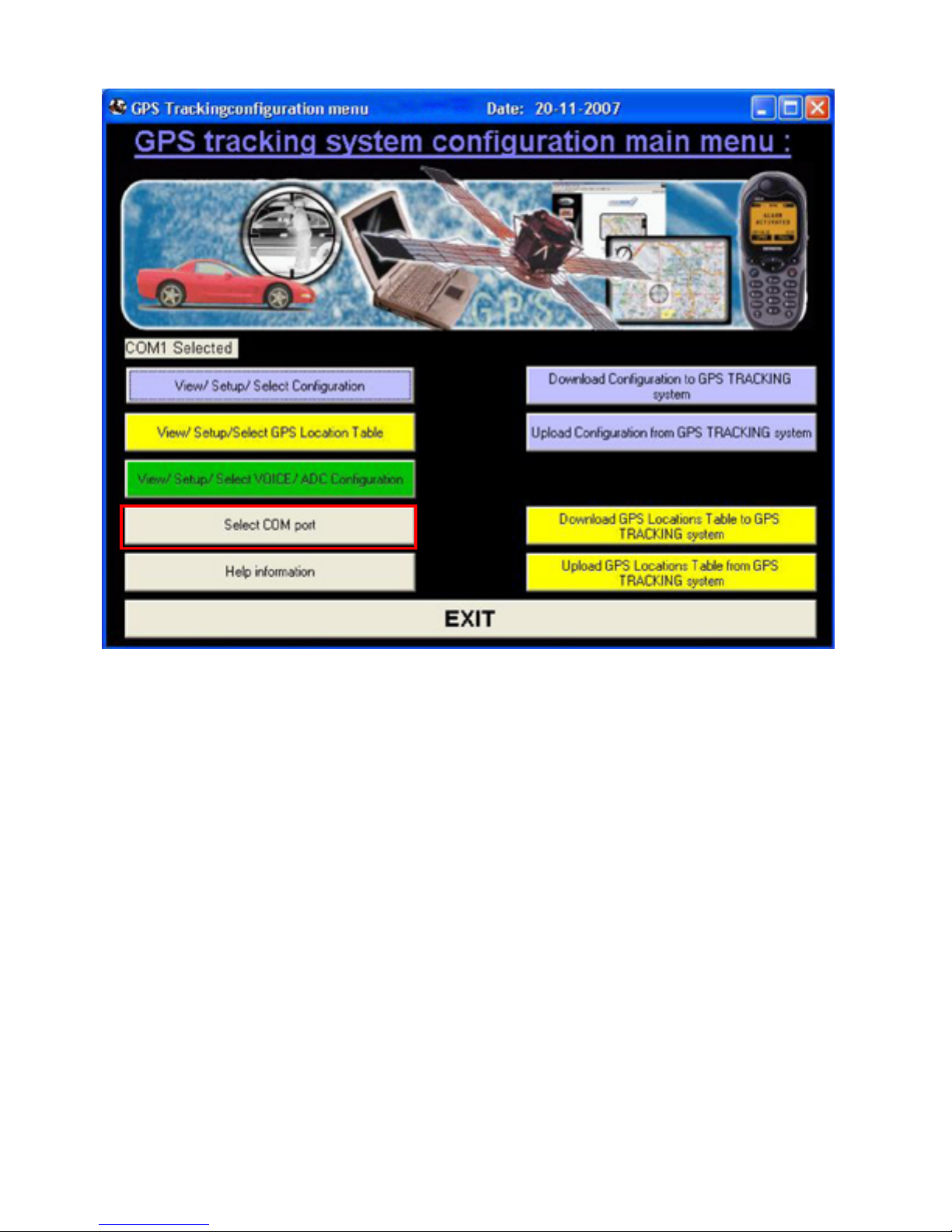
Select Com port
- 13 -
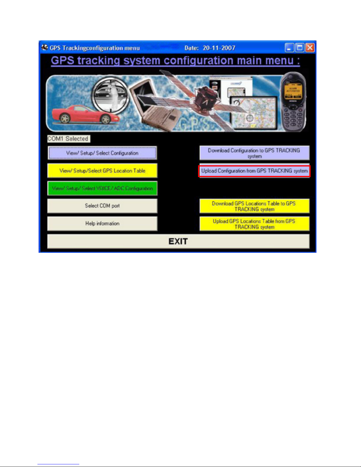
Upload configuration from AVL
After power up you must wait until the unit passes the Diagnostic test.
In Diagnostic test mode you cannot connect to the tracking unit and you
must wait at least 1+ munites before connecting.
In normal running mode (after diagnostic mode) the tracking unit may
also be busy in other processes and the unit will only response to the
configuration software after finishing the process.
Therefore, when upload or download configuration, it may need to wait
for few minutes especially the unit was setup for real time tracking
already.
The best timing to upload the configuration is right after quit from
diagnostic menu with hyper terminal.
- 14 -
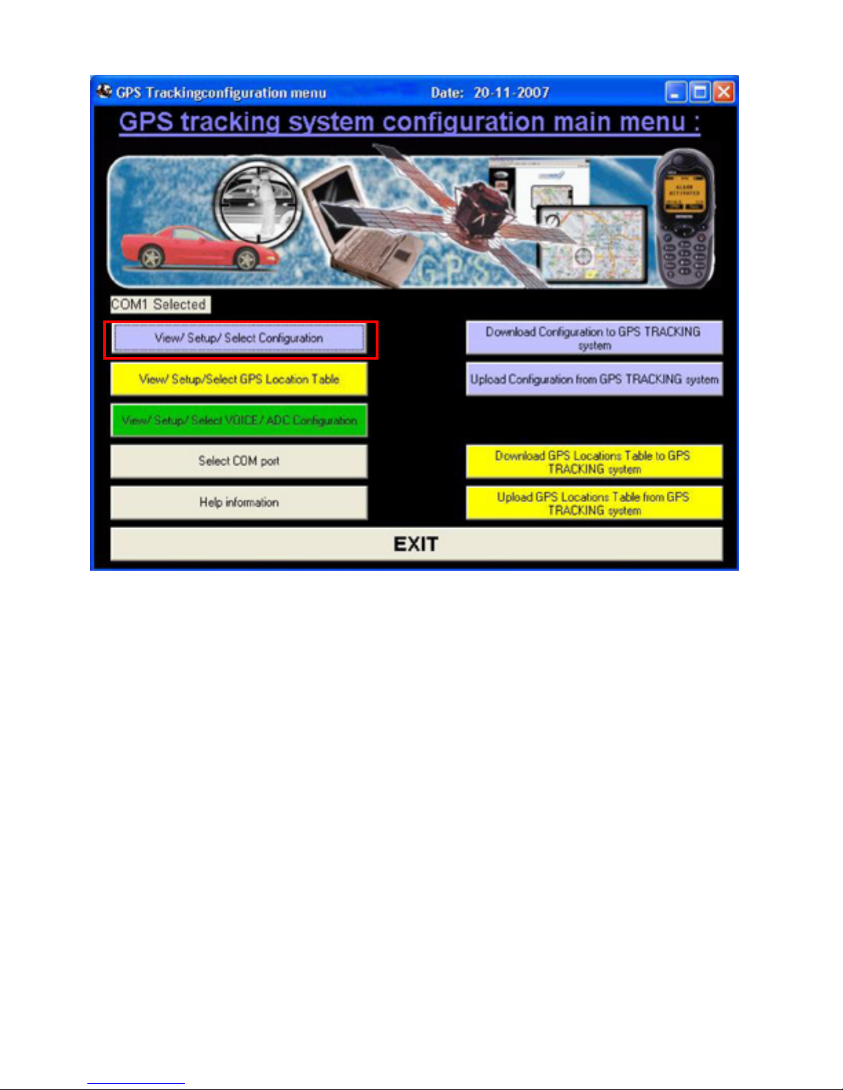
After upload select View/ Select Configuration
- 15 -
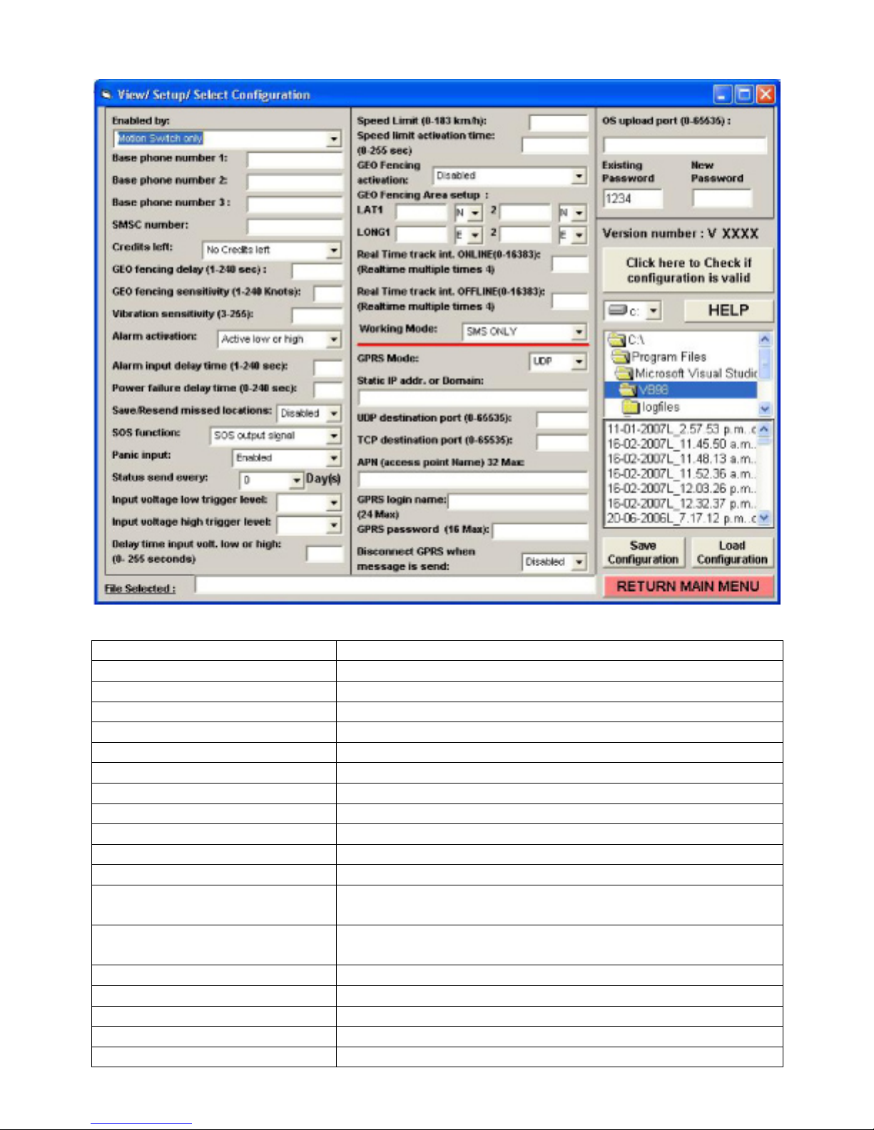
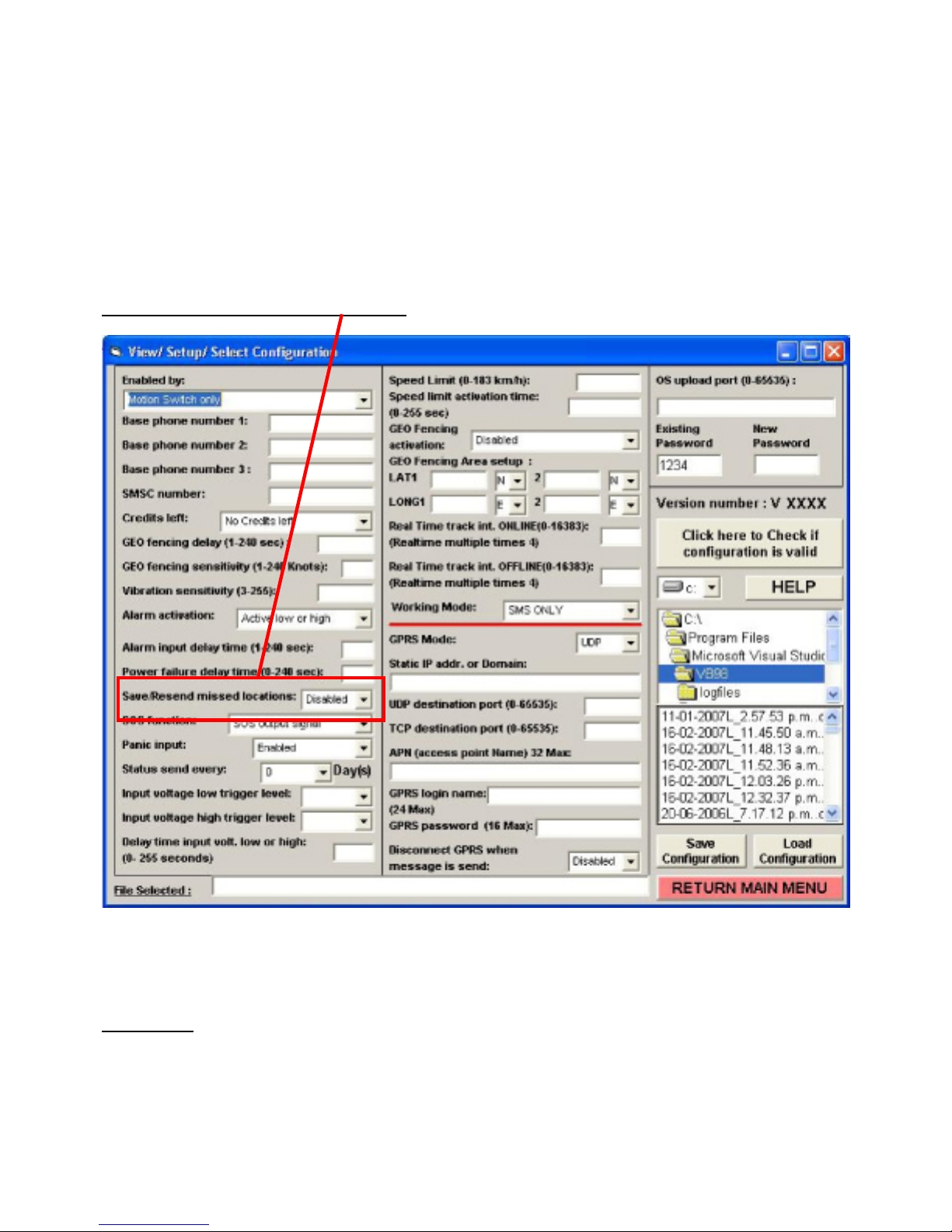
Current configuration
Overview
Settings Description
Enable by Setup how unit activate from sleeping mode (off line)
Base phone number 1: Setup the control center base 1 station number
Base phone number 2: Setup base 2 phone number
Base phone number 3: Setup base 3 phone number
SMSC number: Setup SMSC number if required
Credits left: Disable or enable all out going messages
Geo (PARK) fencing delay Setup the time delay for geo (PARK) fencing
Geo (PARK) fencing sensitivity Setup the speed to activate geo (PARK) fencing
Vibration sensitivity Adjust the sensitivity of motion sensor
Alarm activation Setup the type of alarm input
Alarm input delay time Setup time delay for alarm input
Power failure delay time Setup time delay for external power failure (0=disable)
Will activate if input power is below 7Volt DC.
Save/Resend missed locations: Enable auto save and resend for location messages that
cannot be sent. (*2)
SOS function Setup how SOS output activates
Panic input Disable or enable panic button input
Status send every Send status message every 0-7 day(s)
Input voltage low trigger level Setup low voltage alarm trigger
Input voltage high trigger level Setup high voltage alarm trigger
- 16 -

Delay time input voltage low or
Setup delay time to trigger over or under voltage level
high
Speed limit Over the speed limit will send out message
Speed limit activation time Time of the speed keep over speed limit
Geo fencing activation When setup Geo fencing area, how to react on the geo
fencing
Geo fencing Area setup Rectangle geo fencing area setting
Real Time tracking interval
online
Real Time tracking interval
offline
For SMS only and GPRS only mode and AVL is activating.
(*1)
For SMS only and GPRS only mode and AVL is in sleep
mode. (*1)
Working mode Switch between SMS only mode and SMS+GPRS mode
GPRS Mode: Select between UDP or TCP protocol
Static IP addr. Or Domain
name for GPRS:
Enter static IP address or Domain name to receive GPRS
data
UDP destination port UDP port for GPRS data
TCP destination port TCP port for GPRS data
APN name Access point name for GPRS data
GPRS login name For setup GPRS connection
GPRS password For setup GPRS connection
Disconnect GPRS when
message is send
If enabled will disconnect every time one message is sent
using GPRS
UDP OS update port Setup different port for firmware update via GPRS
Existing password To connect to unit via com port
New password To change the password
Check configuration is valid Check if the setting is valid (This check can only check
basic setup errors)
Select directory Select the directory of setting saved file
Select file Select the setting saved file to load
Load configuration
Load the setting from computer file
Save configuration Save the settings into computer file
File selected The selected file will show in this window
Return to main menu Return to main menu
*1 Minimum Sending time (using GPRS) is about 10 seconds. It will be longer when using SMS for Real
time tracking. Sending time for SMS and GPRS depends on your GSM network speed to confirm and
process SMS and GPRS data commands.
*2 When resend messages is enabled the data compression option ‘Remove comma, points and other
exclamation from GPRS data’ cannot be enabled at the same time.
Please note that the tracking unit has 2 different GEO fencing modes.
For less confusion the ‘GEO’ fencing activated by GEO fencing input (or by SMS/GPS command
message - 21) will be called ‘PARK’ function.
1. The first PARK fencing mode is enabled when the ‘PARK fencing input’ is activated. In this case the
PARK fencing LED will flash to indicate that PARK fencing is activated.
This PARK fencing mode can also be enabled by SMS message. In this case the PARK fencing
activation can only be deactivated by SMS message.
2. The second option allows to configure a rectangle GEO fenced area. The unit can be configured to
respond when a vehicle enters or leaves the GEO fenced area.
- 17 -
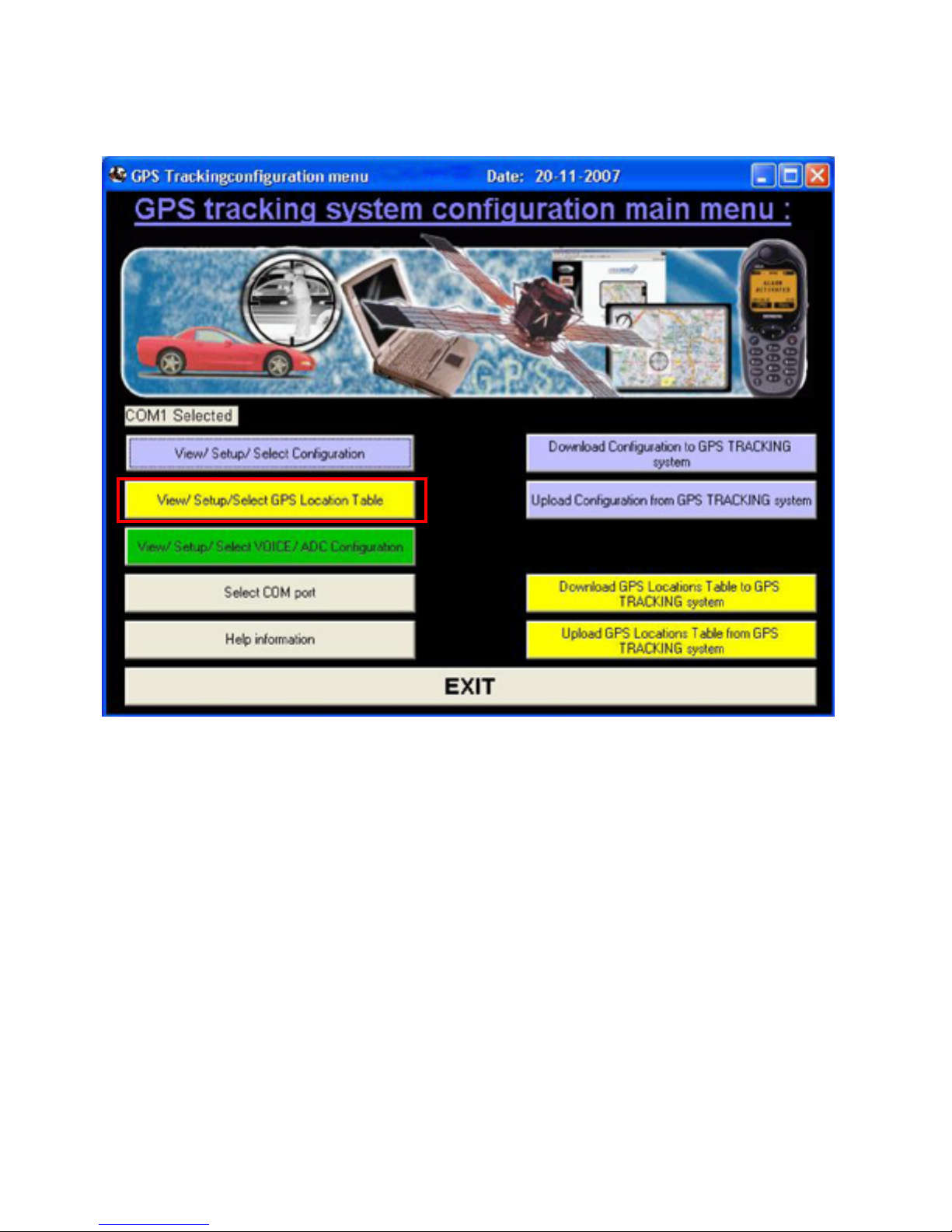
View/ Setup/ Select GPS location Table to edit, add or delete GPS locations in the GPS location table.
The GPS locations in this table can be used for two different functions.
1. As warning device when a vehicle enters an area where a fixed speed camera is installed.
2. As an automatic reporting system when a vehicle enters and leaves a defined location.
- 18 -
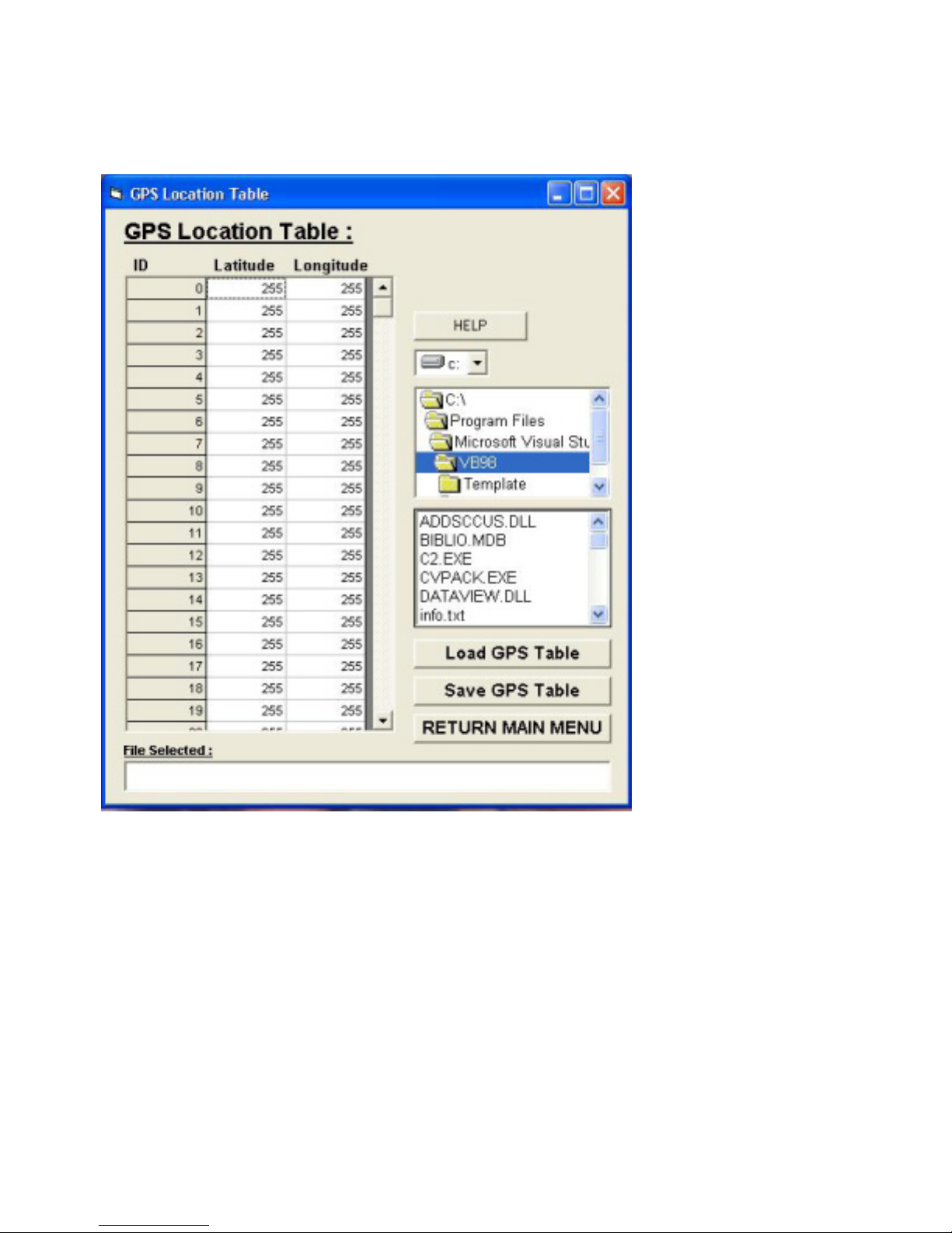
GPS Location Table
Enter Latitude (dd.mmmm) and Longitude (ddd.mmmm) in NMEA format. The tracking unit will only compare
the Latitude and Longitude value to the current GPS location value. Location messages send by the AVL
are always displayed in NMEA format. So they can be used directly in the GPS location table without
conversion.
- 19 -

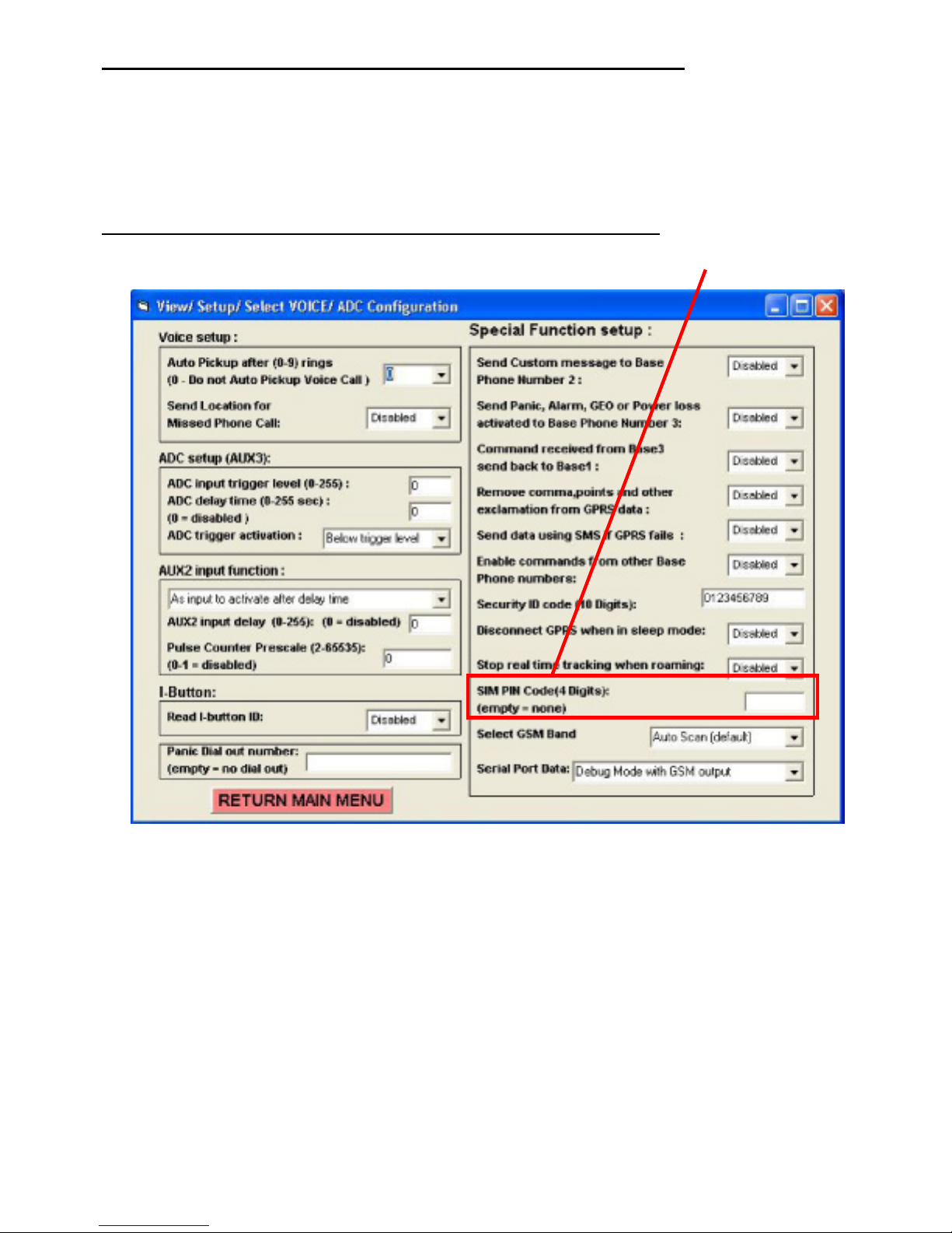
View/ Setup/ Select VOICE/ ADC Configuration
- 20 -
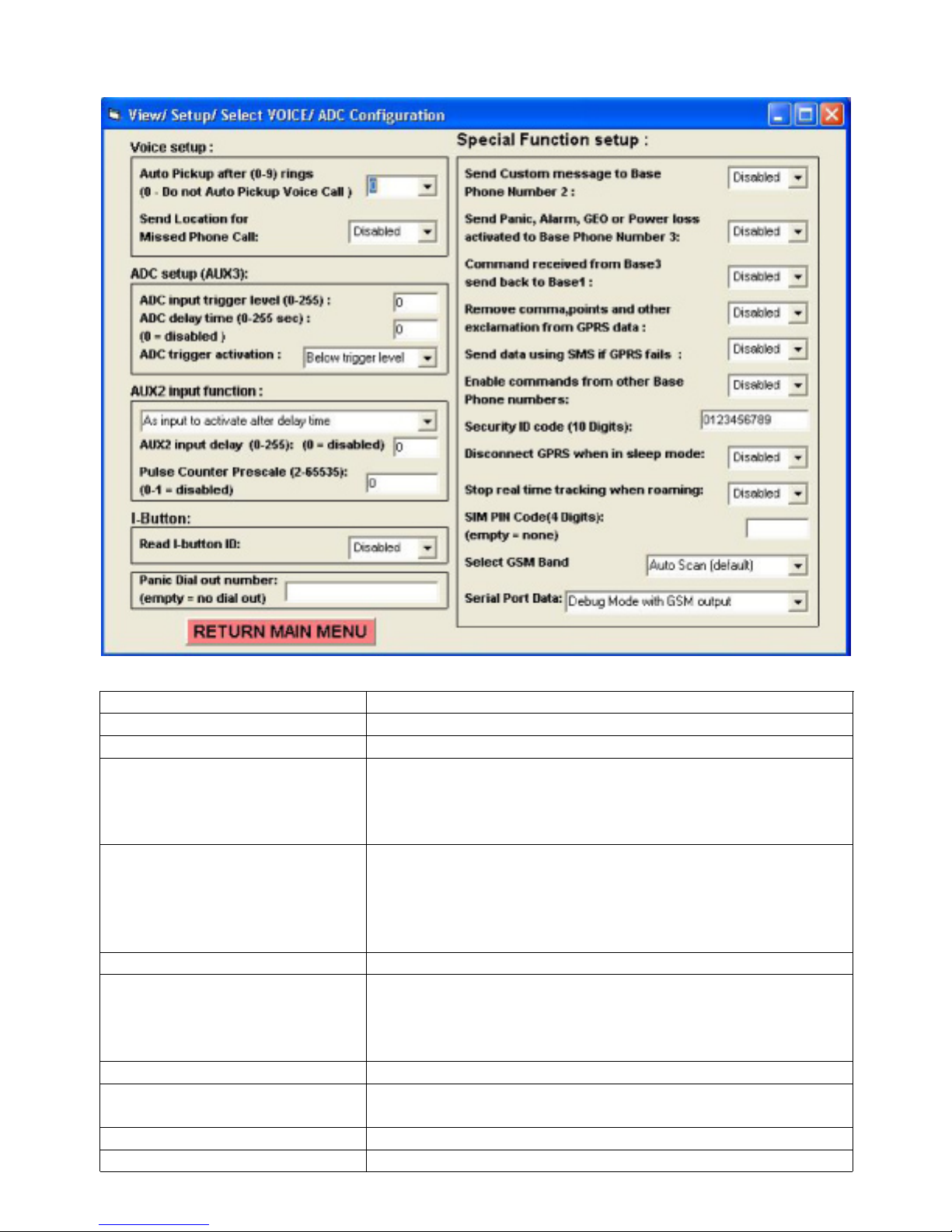
Voice/ ADC Configuration
(This menu also has Special Function setup configuration)
Overview
Settings Description
VOICE SETUP
Auto Pickup after(0-9) rings Setup if the unit will auto pickup incoming voice call
Select Aux2 input to pickup Setup if AUX2 input is used to pickup phone call (Please
note that AUX2 input also can be used to activate as input
alarm trigger. You must select only one function for AUX2
input)
Send Location for Missed
Phone Call
The current or last know location can also be requested
from the AVL after missed Phone call (the call is not
picked up by the AVL). If the AVL picks up the call no
location message is returned. Only for missed calls. (May
not work with all GSM providers or SIM cards)
ADC SETUP (AUX3) * See Note !
ADC input trigger level The input voltage for the analog input must be between 0
and 3.3Volt DC max. The unit uses linear conversion to
convert DC input to numeric value from 0 to 255 (0 is zero
volt and +3.3 Volt is 255)
ADC delay time Setup delay time for ADC input activation
ADC trigger activation Setup if to activate the input below or above the
configured trigger level.
AUX2 input function Select input function for AUX2
AUX2 input delay Configure delay time before AUX2 is activated
- 21 -

Pulse counter Prescale AUX2 must be selected for Pulse Couonter. Select the
Prescale value for the counter.
Read I-Button ID Enable or disable I-Button detection
Panic Dial Out Number Select phone number to dial when Panic Input is
activated. When number is configured the AVL will dial
this number first to make a voice call. The voice call will
be disconnected if the Panic button is activated again (for
1 second or more) or caller hangs up the call (after the call
is connected). The AVL will only try 1 time to call out when
Panic button is activated. After voice call is disconnected
the AVL will send panic activation message. For no dial
out number leave the phone number blank.
SPECIAL FUNCTION SETUP
Send custom message to Base
phone number 2
Send Panic, Alarm, GEO or
Power loss activated to Base
This will send a custom message to Base 2 phone
number
When enabled will also send ‘location message’ to Base
phone number3
Phone number 3
Command received from
All command messages are send to Base 1 only
Base3 send back to Base1
Remove comman, points and
other exclamation from GPRS
data
The ‘location message’ when using GPRS will be reduced
by about 25% to save data communication costs. When
resend messages is enabled the data compression option
‘Remove comma, points and other exclamation from
GPRS data’ cannot be enabled at the same time!
Send data using SMS if GPRS
fails
This will send the data as SMS message if the GPRS
connection fails or is not available. As soon as GPRS is
available again the tracking unit will continue sending data
using GPRS
Enable commands from other
Enable or Disable commands from other Base stations
Base Phone numbers:
Security ID code The unit will only process from other Base station that
have correct security ID code
Disconnect GPRS when in
sleep mode
Stop real time tracking when
roaming
Sim card Code (4 Digits)
When the unit enters sleep mode the GPRS connection is
disconnected
When the unit leaves its home network real time tracking
will stop
Enter pin code for SIM card (See *1)
Select GSM Band Select manual GSM Band. This will force the GSM
modem to only scan and use the selected GSM band.
Normally no need to select manual mode as the GSM
modem will auto scan all GSM bands.
Serial Port Data Select if serial port debug data or SMS text message is
send to the serial port
* Once the ADC input is activated (and message has been sent) the ADC delay time will
be reset back to zero disabling the ADC activation. To reactivate the value must be
reloaded using SMS command or using the configuration menu.
*1
- 22 -
• For the first time when you install a new sim card the pin
number (if configured) must be set to “0000” or disabled. The
pin code can be changed later updated using the configuration
menu.
• MAKE SURE THE PIN NUMBER IS CORRECT BEFORE
INSTALLING SIM CARD. READ SETUP SIM PIN CODE
INSTRUCTIONS FIRST!
If the pin code is incorrect the sim card may get ‘blocked’.
Save/Resend missed location messages:
This option (when enabled) allows the tracking unit to save and resend up to 1700+ messages. Saving the
messages is done automatic when enabled. The complete location message information is saved and
resend when data can be send.
As example:
SMS tracking interval is configured to send location message every 1 minute. After sending data for 2
minutes the AVL enters location where there is NO GSM signal or no GSM provider for 25 minutes.
Then the AVL returns to location where there is GSM signal. During the time there was no GSM signal
the location data is automatic saved to memory. This also includes and activation messages (like Panic
button activated).
- 23 -

Up to 10 saved messages are send each time. After 10 messages are send the AVL will check for any
messages received or any other messages that need to be sent. This will also include ‘Real time tracking
messages’. The data is saved as last one in is first one out. The first data saved will be received last.
Up to 1700 messages can be saved. Once the memory is full no more messages will be saved until
messages can be send back.
If power is lost during saving or sending the AVL will automatic resend the messages from buffer again.
As example there are 100 messages saved in memory. After sending 54 messages input power and battery
power is lost. After power up message sending will resume from message 60 back to 1. The previous 6
messages (60-54) will be resend. The counter value is saved to memory after 10 messages are sent.
If the AVL enters another location where there is no GSM signal then sending will stop and saving will
automatic restart again. Any missed messages that where previous not send are also resend when the
AVL returns to location where there is GSM signal.
Every time the AVL makes a GPRS connection using TCP or UDP it needs to connect to the GSM server
and log in. The login time and connection time can be different between GSM providers. Some commands
connect within several seconds and some can take up to 1 minute to get respond code from GSM provider.
How more options you have selected in the configuration menu and the combination off options can also
make the time different between sending locations data.
When using TCP/IP the connection needs to be valid every time you send data. If your server is switched off
then there will be ‘time out’ before this is detected at the AVL.
This time is also different between GSM providers.
The part that is the slowest is when you are using TCP/IP and your own server fails. This has the longest
delay time between saving GPS locations as ‘time out’ can be very long. No option to speed up as our AVL
can only select GSM, GPS or serial port at one time.
Customer that use UDP have less delay problems, but when there server is down the AVL cannot detect
any failure and no data will be saved or resend. Only communication problems like No GSM signal or GPRS
cannot connect or is disconnected are detected. In that case locations as saved and resend.
When data is resend the sequence is always last one in is first one out. The last memory location can be
resend twice. This happens when sending fails during the time that message needs to be send. The AVL
cannot detect if the message has been send correctly at that time.
There will always be time difference between resend messages at the GPRS connection time is different
every time you connect to GSM provider. Different connection time make different saving time.
- 24 -

Example:
Online Tracking interval 1 minute
Offline Tracking interval 0 minute
Settings enabled
Receive 10 location messages
Receive message by SMS or GPRS
1 min
1 min1 min
No GSM Signal
24
25
Missed messages are numbered
from 1 to 25. (25 last saved one)!
25 Minutes
GSM Signal
The AVL will check for any
new incoming messages
or messages that need to
be sent including real time
messages.
16
1 min 1 min
4 321
5
Last 5 missed locations
14
15
Missed messages are numbered
from 1 to 25. (25 last saved one)!
6
All missed messages have the same format as location messages
Sample:
05*827,000,L001,A,2459.3640,N,12125.2958,E,000.0,224.8,00.8,07:47:26 09-09-05,9.50,D3,0,C4,1
I-Button or odometer is also saved and automatic resend in the location message.
Please Note:
If you are using TCP/IP or if the AVL enters locations where there is GSM signal and the SIM cards
registered, but there is no GPRS service available or your TCP/IP server is not working the time between
locations saved can be different from the one you have selected.
If there is no GPRS service available or your TCP/IP server is not working the AVL will reset the GSM
modem between the sending sessions. This means that the time between locations saved will be between 45 minutes.
- 25 -
More Real time tracking interval samples:
Example 1
Online Tracking interval 5 minutes
Offline Tracking interval 0 minute
Settings enabled
Receive message by SMS or GPRS
5 min 5 min 2 min
2 Hours
Tracking unit wakes up
Example 2
Online Tracking interval 3 minutes
Offline Tracking interval 20 minutes
5 min
Settings enabled
3 min 5 min 3 min3 min1 min 20 min 20 min
Please note that the AVL enters sleep mode after 10-11 minutes. So every time the AVL changes
from ONLINE to OFFLINE tracking interval or from OFFLINE to ONLINE tracking interval you will also
receive one real time tracking interval message.
Receive message by SMS or GPRS
Tracking unit wakes up
- 26 -
Installing SIM card with different PIN NUMBER then 0000 or None:
The default configuration after operating system upload or when you receive the AVL for the first time
is NO SIM PIN number or SIM PIN number is 0000 (4 * zero). If you cannot remove SIM PIN number make
sure that your SIM PIN is configured for 0000.
The AVL will first test if SIM PIN number is required. If the SIM card requires PIN number then the AVL
will try to access the SIM card using the default pin number 0000 (4 * zero).
To change the SIM PIN number you must follow the following instructions.
1. First upload the current configuration from your AVL and set ‘SIM PIN CODE’ to none (empty).
2. Then download the settings to your AVL.
3. Power down the AVL and remove SIM card.
4. Use your normal mobile phone to change the SIM pin number.
5. Insert the SIM card back into the AVL and switch on the AVL.
6. Wait for about 1 minute before using the configuration menu program.
7. Upload the configuration from the AVL.
8. Set the PIN CODE to the new PIN code you have configured (using your mobile phone).
9. Download the configuration to the AVL.
10. DONE.
- 27 -

SMS commands accepted by the tracking unit:
The unit will only process SMS commands sent to the unit. If the unit is configured in SMS and GPRS mode
then any confirm, update or location message is sent back using GPRS.
The unit can read and sent any SMS messages without disconnection from the GPRS connection.
When sending SMS commands please make sure that the message has the correct data format. Some
commands may require a fixed length. We also suggest to only use 1 command change or update in every 1
SMS message.
11, ( Request Current Status, Version, GPS location)
Example: 05*827,11,0
12, -> SMS only mode (default)
Example: 05*827,12,0
13, -> SMS and GPRS mode
Example: 05*827,13,0
14, -> Upload operating system by air using GPRS/ UDP mode
Example: 05*827,14,0
15, -> Upload configuration file by air using GPRS/ UDP mode
Example: 05*827,15,0
16, -> Upload Camera GPS locations by air using GPRS/UDP mode
Example: 05*827,16,0
17,xxxxxxxxxxxxxxxxxxxxxxxxxxxxxxxx, -> APN for GPRS (32 locations max)
(Default 'internet')
Example: 05*827,17,vodafone,0
18,x -> Enable/Disable Saving and Resend missed location messages.
x=0 -> Disable
x=1 -> Enable
Example: 05*827,18,1,0 (Enable Saving and Resend missed location messages)
19,x, (x = 0 UDP mode)
(x = 1 TCP mode)
Example: 05*827,19,1,0 (switch to TCP mode)
20, -> Disable PARK Fencing!
Example: 05*827,20,0
21, -> Enable PARK Fencing!
Example: 05*827,21,0
22,x, ( x = 0 No compression for GPRS real time tracking )
( x = 1 Compression for GPRS real time tracking)
Example: 05*827,22,0,0
23,x, ( x = 0 Do not send data in SMS if GPRS fails for Real time tracking )
( x = 1 Send data in SMS if GPRS fails for Real time tracking)
Example: 05*827,23,1,0 (send data in SMS if GPRS fails for Real time tracking)
24,xxxxx, -> TCP Destination Port (6082 decimal – Default – from 0 to 65535)
Example: 05*827,24,6082,0 - TCP Destination Port !
25,xxxxx, - > UDP destination Port (6080 decimal – Default- from 0 to 65535)
Example: 05*827,25,6080,0 - UDP Destination Port !
- 28 -
 Loading...