

Page 1

NVR 4 canaux H264
User’s Manual
Version 1.1
NVR1641
Page 2
NVR User’s Manual
1
Caution and Preventive Tips
Handle with care, do not drop the unit
Mount the unit in an equipment rack or place it on a solid, stable surface
Indoor use only. Do not place the unit in a humid, dusty, oily, or smoky site
Do not place it in an area with poor ventilation or in an area close to fire or other sources of
heat. Doing so may damage the unit as well as cause fire or an electric shock
When cleaning is necessary, shutdown the system and unplug the u
nit from the outlet
before uncovering the top cover. Do not use liquid cleaners or aerosol cleaners. Use only
a damp cloth for cleaning
Always shutdown the system prior connecting or disconnecting accessories, with the
exception of USB devices
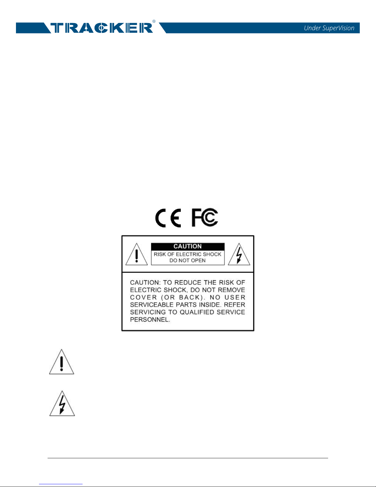
This symbol intends to alert the user to the presence of important operating and
maintenance (servicing) instructions in the literature accompanying the
appliance.
This symbol intends to alert the user to the presence of unprotected “Dangerous
Voltage” within the product’s enclosure that may be strong enough to cause a
risk of electric shock.
Page 3

NVR User’s Manual
2
Important Information
Before proceeding, please read and observe all instructions and warnings in this manual.
Retain this manual with the original bill of sale for future reference and, if necessary, warranty
service. When unpacking your unit, check for missing or damaged items. If any item is missing,
or if damage is evident, DO NOT INSTALL OR OPERATE THIS PRODUCT. Contact your
dealer for assistance.
Rack Mounting
Consult with the supplier or manufacturer of your equipment rack for the proper hardware and
procedure of mounting this product in a safe fashion. Avoid uneven loading or mechanical
instability when rack-mounting units. Make sure that units are installed to get enough airflow
for safe operation. The maximum temperature for rack-mounted units is 40 °C. Check product
label for power supply requirements to assure that no overloading of supply circuits or over
current protection occurs. Mains gro
unding must be reliable and uncompromised by any
connections.
Page 4

NVR User’s Manual
3
Table of Content
1. Overview ....................................................................................................................... 5
2. System Setup ................................................................................................................ 6
2.1 Position the Unit ................................................................................................... 6
2.2 Connect Devices to the Unit ................................................................................ 6
2.3 Log In / Log Out / Reboot / Shutdown .................................................................. 7
2.3.1 Login / Logout ......................................................................................... 7
2.3.2 Reboot / Shutdown ................................................................................. 8
3. Live View ....................................................................................................................... 9
3.1 Live View Window ................................................................................................ 9
3.1.1 View Layout Setup ............................................................................... 12
3.1.2 Snapshot .............................................................................................. 13
3.1.3 Audio Recording ................................................................................... 13
3.1.4 Digital Zoom ......................................................................................... 13
3.1.5 Event Icons...........................................................................................
14
3.1.6 Camera PTZ Control ............................................................................ 14
3.1.6.1 PTZ Control Icons ................................................................... 14
3.1.6.2 Set Preset Points .................................................................... 15
3.1.6.3 Call Preset Points ................................................................... 16
3.1.6.4 Set a Camera Tour Path .......................................................... 16
3.1.6.5 Run a Camera Tour Path ........................................................ 16
3.1.7 Camera Image Setup ........................................................................... 16
3.1.8 Camera Video Format .......................................................................... 17
3.1.9 Camera Motion Setup .......................................................................... 17
3.1.10 Camera Information .............................................................................. 18
4. Genera NVR Configuration ........................................................................................ 19
4.1 Language Setup ................................................................................................ 19
4.2 Ge
neral Setup .................................................................................................... 20
4.2 System Setup .................................................................................................... 22
4.2.1 Date/Time Setup................................................................................... 22
4.2.2 Event Setup .......................................................................................... 24
4.3 Network Setup ................................................................................................... 26
4.3.1 Ethernet Setup ..................................................................................... 26
4.3.2 Email Setup .......................................................................................... 29
4.3.3 DDNS Setup ......................................................................................... 31
4.4 Storage Setup .................................................................................................... 33
4.5 User Management Setup ................................................................................... 34
4.6 Display Setup ..................................................................................................... 36
4.7 PoE Management .............................................................................................. 37
Page 5

NVR User’s Manual
4
5. Add Device (IP Camera Connection) ........................................................................ 39
5.1 Add Device Window ........................................................................................... 39
5.2 IP Camera Connection....................................................................................... 42
6 Record ......................................................................................................................... 43
6.1 Record Schedule Setup ..................................................................................... 43
6.2 Record Setup ..................................................................................................... 44
7 Playback/Export.......................................................................................................... 46
7.1 Playback Control Bar ......................................................................................... 46
7.2 Search / Playback / Export Normal Videos ........................................................ 47
7.3 Search / Playback / Export Event Videos........................................................... 48
7.4 View / Export Snapshots .................................................................................... 50
8 Log ............................................................................................................................... 52
8.1 Search Log Data ................................................................................................ 52
8.2 Export Log Data ................................................................................................. 52
Page 6

NVR User’s Manual
5
1. Overview
The NVR 4 CH H.264 is a premium network video recorder featuring
multiple functions of a time-lapse audio/video recorder, a multiplexer, and a
video server, which provides a comprehensive security solution.
Integrated simple and instinctive UI design, the NVR 4 CH H.264 is easy
for users to operate and brings users the flexibility to self-define the NVR or
IP camera settings based on their needs. Equipped with 4/8/16 Power over
Ethernet (PoE) ports, the NVR 4 CH H.264 simplifies the procedure of IP
cameras connection. The PnP and Auto Add function help users setup the
configuration of the connected IP cameras without much effort. Besides, the
NVR supports up to 8M video resolution, presenting superb image quality
and displaying up to 24 channels live view simultaneously.
The NVR 4 CH H.264 is pre-installed with remote viewing and
configuration software, allowing users to watch live view and recorded videos
and even to operate NVR configuration remotely via internet connect
ion.
Page 7
NVR User’s Manual
6
2. System Setup
The notices and the introduction on system installation will be described
particularly in this chapter. Please follow the description to operate the unit.
In order to prevent the unit from data loss and system damage caused by a
sudden power fluctuation, use of an Uninterruptible Power Supply (UPS) is
highly recommended.
2.1 Position the Unit
Firstly, note to position/mount the NVR in a proper place and be sure to
power off the unit before making any connections. The placed location should
avoid hindering or blocking the unit from airflow. Sufficient airflow is needed
to protect the unit from overheating. The maximum allowable temperature of
operating environment is 40°C.
The unit utilizes heat-conducting techniques to transfer internal heat to the
case, especially to the bottom side of the unit.
NOTE: Be sure the rubber feet are not removed, and always leave a
space for air ventilation on the unit’s bottom side.
2.2 Connect Devices to the Unit
This section lists some notices that should be given before making any
connections to the NVR.
Connecting Required Devices
Before powering on the unit, a USB mouse, a USB keyboard, network
connection, and a main monitor must be connected to the unit for basic
operation.
Connecting Short-term Device
If any short-term devices shall be installed to the NVR as a part of the unit
system, such as USB ThumbDrive® or any USB devices, etc., make sure
those devices are connected only after the unit is powered on. The reason is
that the NVR can recognize the external devices only after the power-on
process is done completely.
Page 8
NVR User’s Manual
7
2.3 Log In / Log Out / Reboot / Shutdown
This section describes how to login / logout when the NVR system is started.
How to reboot and shutdown the NVR system is also described below.
2.3.1 Login / Logout
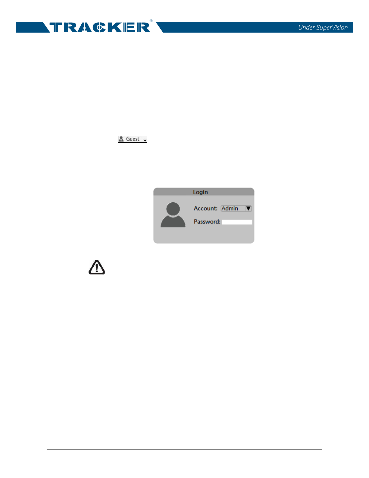
Once the NVR is powered on, the Live View will be displayed, and the preset
logged-in user account will be “Guest”. To login the NVR system as the
administrator, move the mouse cursor to the top-right corner of the monitor,
click on < > and select <LogOut>; a login window will be displayed.
Select the adm
inistrator account, “
Admin
” and click on the Password field
twice. A virtual keyboard will pop up. Input the preset password “
123456
”, and
click on <OK> to login the NVR system as the administrator.
NOTE: It is strongly suggested to change the preset password to
prevent unauthorized access to the unit.
To log out the currently logged-in user account, just click on the username,
and select <LogOut>.
Page 9
NVR User’s Manual
8
2.3.2 Reboot / Shutdown
To reboot or shutdown the NVR, please follow the correct reboot or shutdown
procedure to avoid damaging the NVR.
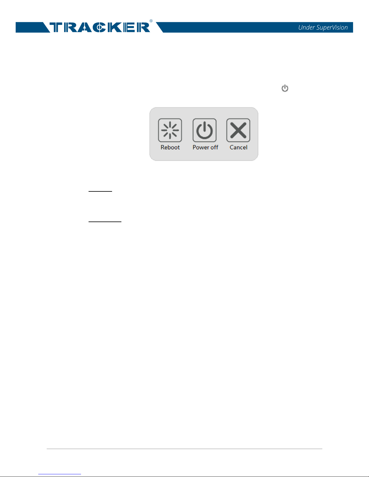
Click on the Power icon at the top-right corner of the monitor, < >, and the
Power panel will show up as below.
Power Penel
Reboot
Select the Reboot icon, and the NVR system will begin the reboot procedure.
Shutdown
Select the Power Off icon, and the NVR system will start the shutdown
procedure. Do not remove the power source until the NVR is completely off.
Page 10
NVR User’s Manual
9
3. Live View
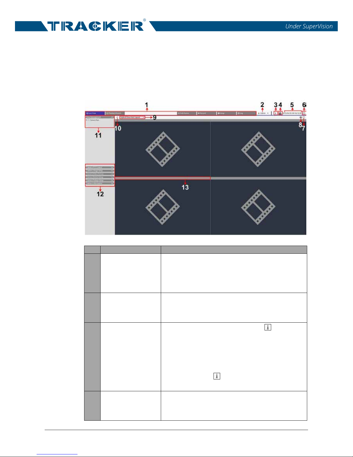
When the NVR starts up, the NVR Live View Window will be shown. The
following further describes each item in the Live View.
3.1 Live View Window
No.
Item
Description
1 Function Tabs
There are six function tabs, including <Live
View>, <Playback/Export>, <Add Device>,
<Record>, <Setup> and <Log>. Each function
tab will be further introduced in later sections.
2
User
Login/Logout
Login the NVR system with the authorized user
account or logout the currently logged-in user
account here.
3 System Info
Click on the System Info icon, < >, and the
NVR System Info Pane will be displayed on the
right of the monitor. Users can view the NVR
software version, CPU status, RAM (memory)
usage, HDD space and network throughput
here. Click on < > again to hide the System
Info Pane.
4
System
Notification
When the NVR is overheated or the HDD space
is full, this icon will turn red to notify users. Click
on the icon to display the warning messages.
Page 11
NVR User’s Manual
10
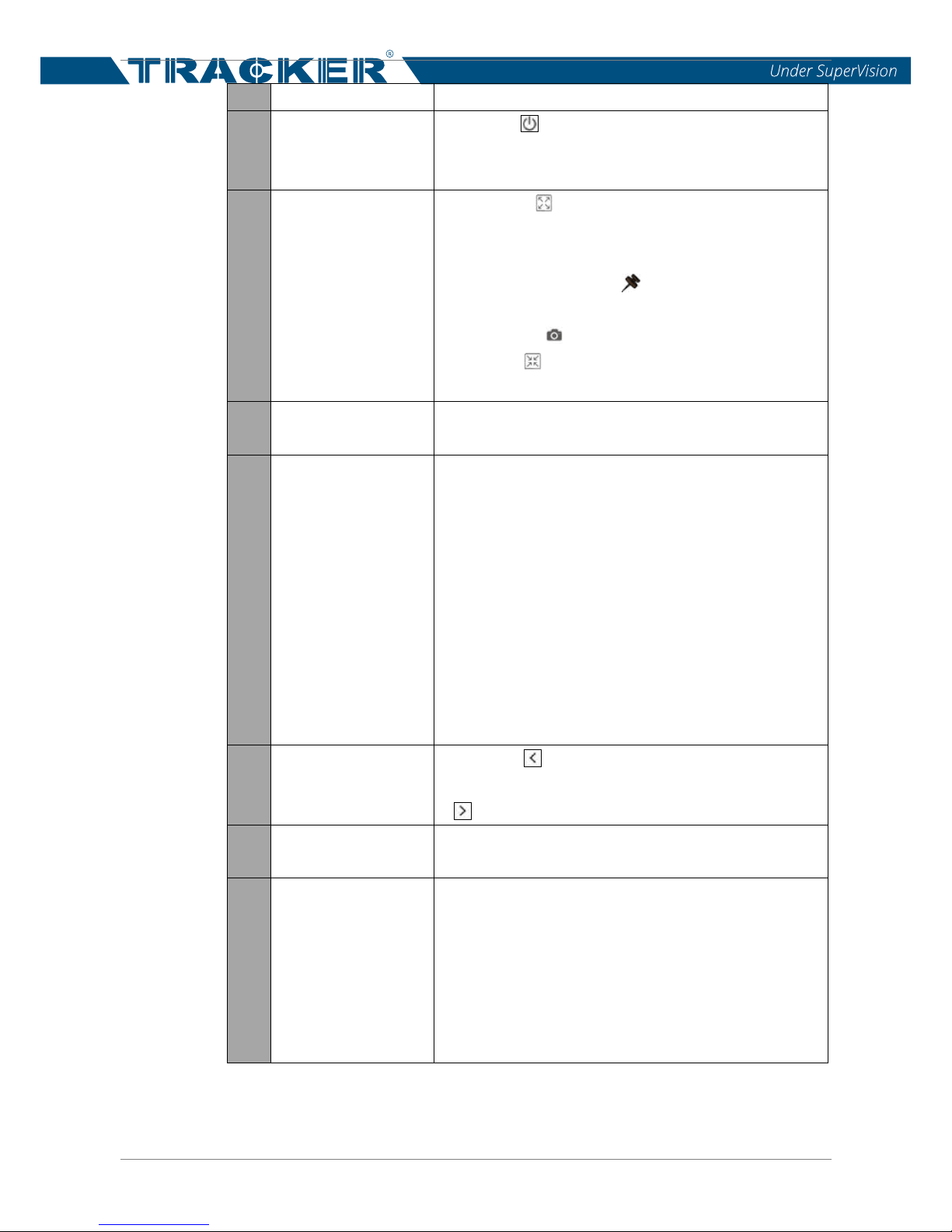
5 Date/Time
This shows the current date/time information.
6 Power Panel
Click on < > to display the Power Panel. Select
the corresponding option to safely reboot or
shutdown the NVR system.
7 Full-Screen
Click on < >, and the NVR will enter the
full-screen mode. Move the mouse cursor to the
top-center of the monitor, and a float function bar
will show up. Click on < > to fix the function bar.
Users can capture the current viewing image by
clicking on < >. To exit the full-screen mode,
click on < >, and the NVR will return to the
previous viewing mode.
8 Snapshot
This function is used to capture the current
viewing in Live View or Playback/Export tab.
9
View Layout
Setup
The NVR provides two view layouts, <Video
View Auto Layout> and <Video View Custom
Layout>.
Video View Auto Layout: The NVR will
automatically adjust the layout to the suitable
layout format when new IP cameras are added
to the NVR.
Video View Custom Layout: Users can
self-define and setup at most 4 sets of view
layouts. The following section will further
describe how to setup a view layout.
10 Hide View Pane
Click on < > and the View Management Pane
and Camera Setup Pane will be hidden. Click on
< > to show the pane.
11
View
Management
The NVR will list all connected IP cameras under
the View Management Pane.
12
Camera Setup
Panes
Users are able to setup several settings of the
connected IP camera, including <Camera PTZ
Control>, <Camera Image Setup>, <Camera
Video Format>, and <Camera Motion Setup>.
Besides, users can check the basic information
of the selected IP camera under <Camera
Information>.
Page 12
NVR User’s Manual
11
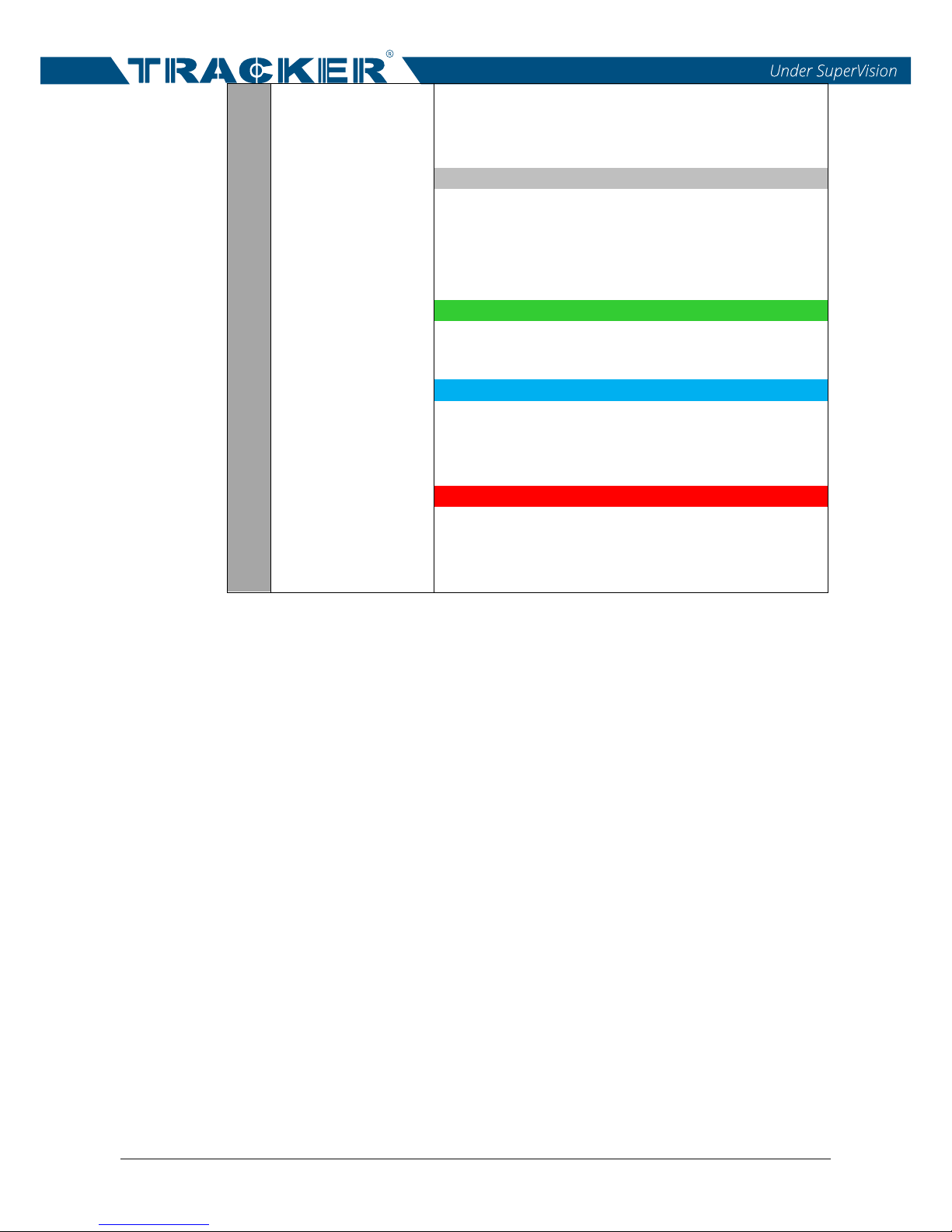
13 Camera Title Bar
The camera title bar is above each channel grid.
Users can check the connection status of the IP
camera by the color of the title bar.
Grey
When the NVR is started for the first time or
currently not connecting to any IP cameras, the
title bar is in grey. This indicates no IP camera is
connected to the channel grid.
Green
If the title bar is in green, this suggests that the
NVR is connecting to the IP camera.
Blue
When the title bar is in blue, this means the
connection between the NVR and the IP camera
is in good condition.
Red
If the NVR tries to connect the IP camera but
fails, the title bar will be in red, which represents
failed connection to the IP camera.
Page 13
NVR User’s Manual
12
3.1.1 View Layout Setup
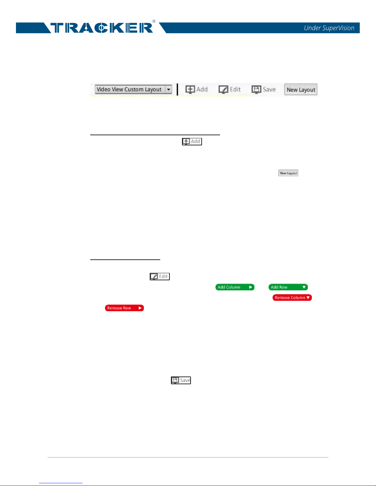
If users wish to setup their preferred NVR display layout, select <Video View
Custom Layout> and its setting items will be shown as below.
Follow the description below to add, edit, save and delete a display layout.
Add / Rename / Delete a Display Layout
To add a layout, click on < >, and a new layout will be added to the
layout list.
To rename a layout, right click the layout name, e.g. < >, select
<Edit name> from the drop-down menu and rename the selected layout.
Click on <OK> to save the setting or click on <Cancel> to abort.
To delete a layout, right click the desired layout item and select
<Remove> from the drop-down menu. The layout will be removed from
the layout list.
Edit a Display Layout
Select the layout that is wished to be modified from the layout list.
Then, click on < > to enter its layout setup mode.
To add more channel grids, click on < > / < >.
To remove the added columns/rows, click on < > /
< >.
To resize a channel grid, first click on a channel grid. Then click and drag
any corner of the yellow frame to draw a preferred grid layout. When
finishing the drawing, release the mouse.
Two different channels can be swapped. Click and drag any channel fr
om
its original grid to the desired grid and drop the channel. The two channels
will be switched.
After setting, click on < > to save and apply the layout setting.
Page 14
NVR User’s Manual
13
3.1.2 Snapshot
The NVR allows users to capture the current viewing image in Live View or in
Playback/Export tab.
Click on < > at the top-right of the monitor, and the current viewing will be
captured. Click on <Save> from the pop-up Snapshot Window to save the
captured image (screenshot), or click on <Discard> to cancel. Users can view
and export the snapshots in the Playback/Export tab.
3.1.3 Audio Recording
This item is used to switch on/off the audio of the selected IP camera
channel.
Move the mouse cursor to any channel grid, and an Audio icon < > will
show up. Click on < >; the audio function will be enabled and the icon will
be switched to < >. Furthermore, another Audio icon < > will be
displayed at the bottom-left of the channel grid to notify users that the Audio
of the IP camera is currently switched to ON.
To disable this function, just click on < >.
NOTE: The Audio function can only be enabled a channel a time.
3.1.4 Digital Zoom
Users can view the camera zoom-in images via digital zoom function.
Move the mouser cursor to any channel grid and scroll up/down the mouse
wheel to zoom in/out. The zoom-in magnification will be displayed on the top
left corner of the grid. The maximum magnification is 7x. Note that in single
channel full-screen mode, the maximum magnification is 10x. Click at any
position to set the position as the center of the display screen.
Page 15
NVR User’s Manual
14
3.1.5 Event Icons
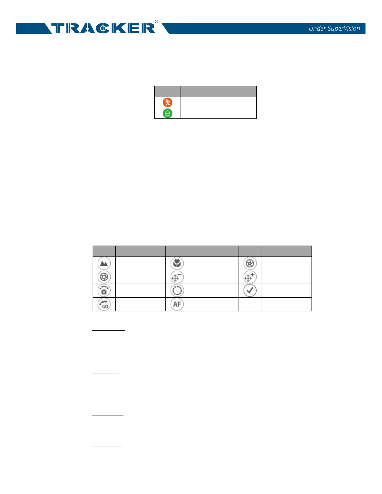
When an alarm/event occurs, the icon corresponding to the event type will
show up at the bottom-left of the channel grid.
Icon
Description
Motion detection
Alarm input triggered
3.1.6 Camera PTZ Control
The NVR supports PTZ control function. In Live View, select a camera
channel that equips pan/tilt/zoom function and expand the Camera PTZ
Control Pane on the left of the monitor.
3.1.6.1 PTZ Control Icons
The PTZ control icons are Zoom Out/In, Focus Far/Near, Iris Open/Close,
Preset, Auto Focus and Direction Control Panel. The functions are described
as below.
Icon
Description
Icon
Description
Icon
Description
Zoom Out
Zoom In
Iris Close
Iris Open
Focus Far
Focus Near
Set Tour
Go Tour
Set Preset
Go Preset
Auto Focus
Zoom Out
Click on it to zoom out the lens of selected camera. This function is to shrink
the current image and a larger viewing area can be displayed.
Zoom In
Click on it to zoom in the lens of selected camera. This function is to enlarge
a certain area.
Iris Close
Click on it to shrink the Iris on the selected camera.
Iris Open
Click on it to open the Iris on the selected camera.
Page 16

NVR User’s Manual
15
Focus Far
Click on it to focus the lens of selected camera at a farther point.
Focus Near
Click on it to focus the lens of selected camera at a nearer point.
Tour
This function is to setup at most 8 tour paths of the camera and execute the
tour path for viewing.
Preset
This function is to set up certain position as a preset point and go to the
predetermined preset positions for viewing.
Auto Focus
Click on this button to automatically adjust focus of the selected camera.
Direction Control Panel
Click and drag the control button (in the center of the panel) to pan and tilt the
lens of the selected camera. The pan/tilt speed depends on the distance
between the control button and the Direction Control Panel. The farther the
control button is dragged from the center of the panel, the faster the pan/tilt
speed is, and vice versa.
3.1.6.2 Set Preset Points
The NVR allows users to set preset positions. The amount of preset points
depends on the camera manufacturer.
Follow the st
eps to set preset points.
Click on a camera channel that equips preset point function.
Select a preset number from the preset list.
Use the Direction Control Panel to pan/tilt the camera to the desired
position.
Click on < > to save the position.
Page 17

NVR User’s Manual
16
3.1.6.3 Call Preset Points
Follow the steps to call preset points.
Click on a camera channel that equips pan/tilt/zoom function.
Select a preset point number from the Preset Point List.
Click on < > to call the preset point. The selected camera will
automatically move to the preset position.
3.1.6.4 Set a Camera Tour Path
The NVR allows users to set Tour Path. Follow the steps to set tour paths.
Click on a camera channel that equips pan/tilt/zoom function.
Select a tour path number from the Tour Path l
ist.
Click on < > to start recording the tour path.
Use the Direction Control Panel to pan/tilt the camera to set a tour path.
After setting, click on < > to save the position.
3.1.6.5 Run a Camera Tour Path
Follow the steps to run the camera tour path.
Click on a camera channel that a camera tour path is already set.
Select a Tour Path number from the Tour Path List.
Click on < >, and the camera will start touring as recorded.
Click on Direction Control Panel to end the camera tour.
3.1.7 Camera Image Setup
Users can configure the image settings of the selected IP camera. The image
settings include image adjustment, noise reduction, white balance, etc.
Users should first click the desired IP camera channel and then start the
setting. When users are adjusting image configuration, users can then watch
the channel grid to check the change of image setting. After setting, click
<Apply> to save the setting.
NOTE: Some setting items may be unavailable for certain IP camera
models. Thus, those setting items will be grayed out and cannot be
accessed.
Page 18

NVR User’s Manual
17
3.1.8 Camera Video Format
Users can configure the settings of video format. The video format settings
include video resolution, video rotate, H.264 profile, CBR/VBR mode, etc.
Users must click on <Apply> after setting. Otherwise, the setting will not be
saved.
NOTE: Some setting items may not be available for certain IP camera
models. Thus, those setting items will be grayed out and cannot be
accessed.
3.1.9 Camera Motion Setup
Users can setup the configuration of motion detection here. Motion detection
settings include sampling, detection level, sensitivity, time interval and motion
detection areas. Click on any IP camera channel and select <Camera Motion
Setup> to enter the motion setup mode. The following is the description of
each item.
Sampling:
This item is used to examine the differences between two frames. Users can
configure the interval of sampling pixel. For instance, if users set the interval
as 5. IP camera system will take one sampling pixel from every
5 pixels of
each row and each column in detection area. The alarm will be triggered
when differences are detected.
Detection Level:
Users can configure detection level for each sampling pixel. Detection level is
how much the camera can accept the differences between two sampling
pixels. The smaller the value is, the lower the detection level.
Sensitivity:
This item is used to set the detection sensitivity. A greater value indicates
higher sensitive motion detection.
Time Interval:
This item is used
to adjust the time interval between each detection motion.
Page 19
NVR User’s Manual
18
Detection Area Setup
Under motion setup mode, a red frame (detection window) will be displayed
on the channel grid. Note that the amount of motion detection areas may vary
from different IP camera models. Refer to the following to setup motion
detection windows.
To change the location of the motion detection window, click on the center
of the detection window and move it to the desired location.
To resize the detection window, click and drag the edge of the red frame.
To add a new detection window, right click on the channel grid and select
<Add New Window> from the drop-down list.
Click on <Apply> to save the setting to the selected IP camera channel.
Then follow the description above to setup the added detection window.
To remove a motion detection window, first select a desired detection
window, and then right click on the channel grid.
Then, select <Remove Selected Window> from the drop-down list. The
selected detection window will be removed. Alternativ
ely, users can
remove all detection windows by selecting <Remove All Window> from
the drop-down list.
Click on <Apply> to save the setting to the selected IP camera channel.
3.1.10 Camera Information
Users can check the brief information of the connected IP cameras. Click on
any IP camera channel from the display window or from View Management
pane, and the basic information of the IP camera will be listed in Camera
Information pane. The brief information includes site name, IP address,
device type, video format, etc.
Page 20
NVR User’s Manual
19
4. Genera NVR Configuration
In the Setup function tab, users can setup the basic NVR settings, such as
network, factory default, date/time setup, user account management, etc.
Click on <Setup> to enter the general NVR configuration menus.
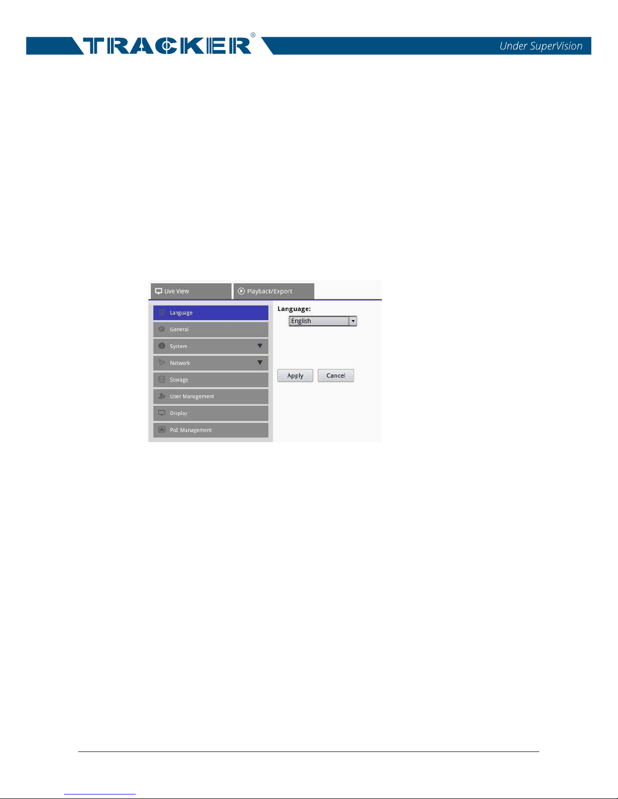
4.1 Language Setup
In the Setup function tab, select <Language> to enter the language setting
menu. Select the preferred language from the language drop-down list and
click on <Apply> to save and apply the setting. Otherwise, click on <Cancel>
to cancel the setting.
Page 21
NVR User’s Manual
20
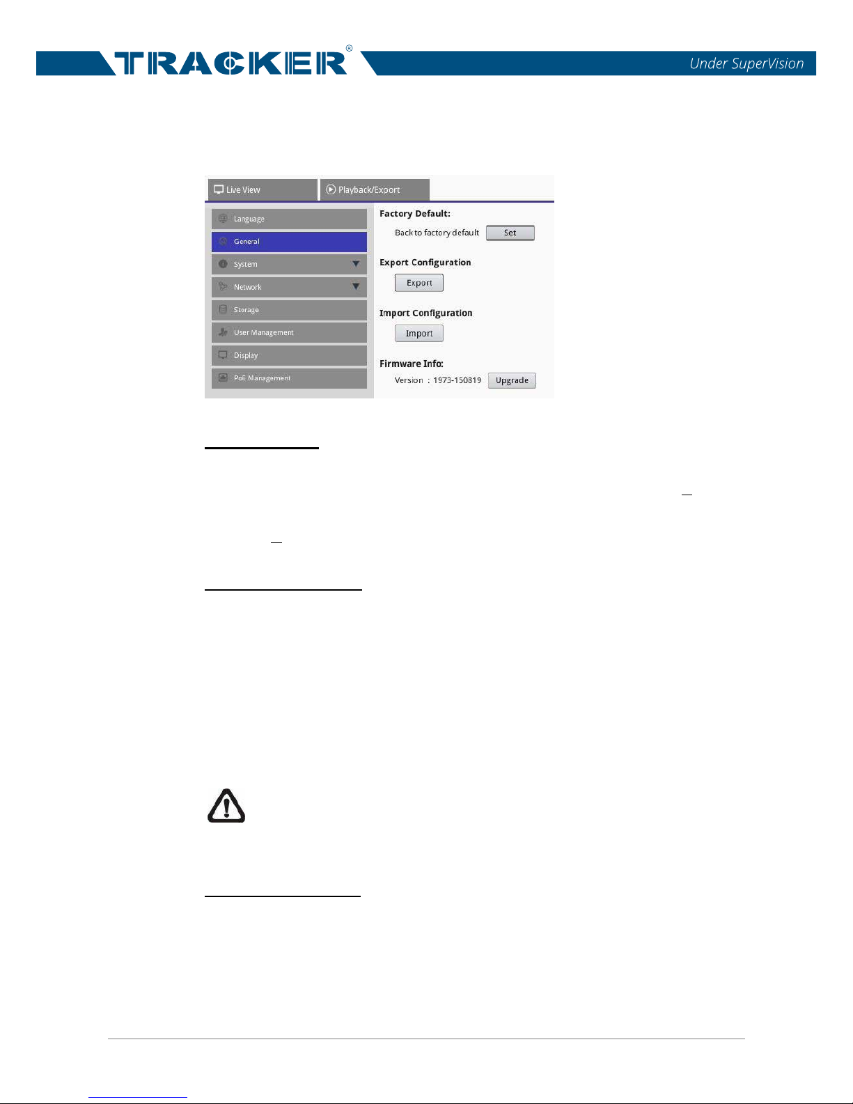
4.2 General Setup
Select <General> to enter the basic NVR setting menu.
Factory Default
This item is used to load the factory default setting of the NVR. Click on
<Set> and a warning message window will show up, click on <Yes> to
proceed and the NVR will reboot after loading the default setting. Otherwise,
click on <No> to abort the factory default procedure.
Export Configuration
This item allows users to save and export the current NVR configuration to an
external drive, such as a USB Flash Drive.
Before exporting the configuration file, ensure that an external drive is
connected to the NVR. Then, click on <Export> and an Export window will be
displayed. Click on <Confirm> to start the exportation, or click on <Cancel> to
abort.
NOTE: It is recommended to export configuration before upgrading
the NVR system. In addition, to backup the configuration routinely is
recom
mended, in case for unexpected conditions.
Import Configuration
This item is used to load an NVR configuration file that was previously stored
in an external drive.
Connect the external drive that stores the configuration file to the NVR. Click
on <Import> and a warning message will show up, notifying users that the
Page 22
NVR User’s Manual
21
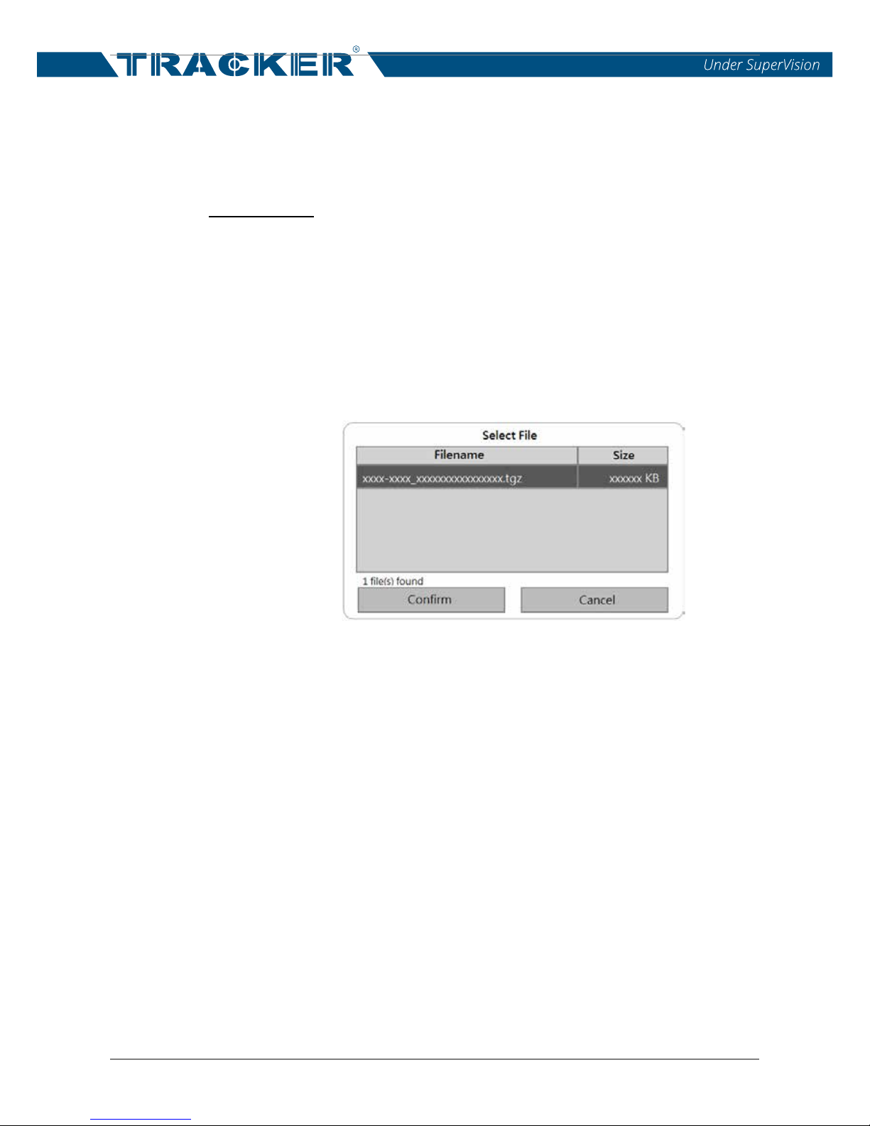
NVR system will reboot after importing the configuration file. Select <Yes> to
proceed or choose <No> to cancel. Then, a Select File window displays and
users can select which configuration to be imported to the NVR. Click on
<Confirm> to start file importing, or click on <Cancel> to abort.
Firmware Info
Users can view the current firmware version of the NVR here. Besides, users
can also upgrade the firmware by local device. Refer to the following for
firmware upgrade procedure.
Firmware Upgrade
First, connect a USB storage device storing upgrade firmware to the
NVR. Click on <Upgrade> and a Select File window will pop up as
below.
Then, select the desired *.tgz file and click on <Confirm>, and the
NVR system will start the firmware upgrade progress. The NVR will
automatically reboot after the syste
m is successfully upgraded.
Page 23
NVR User’s Manual
22
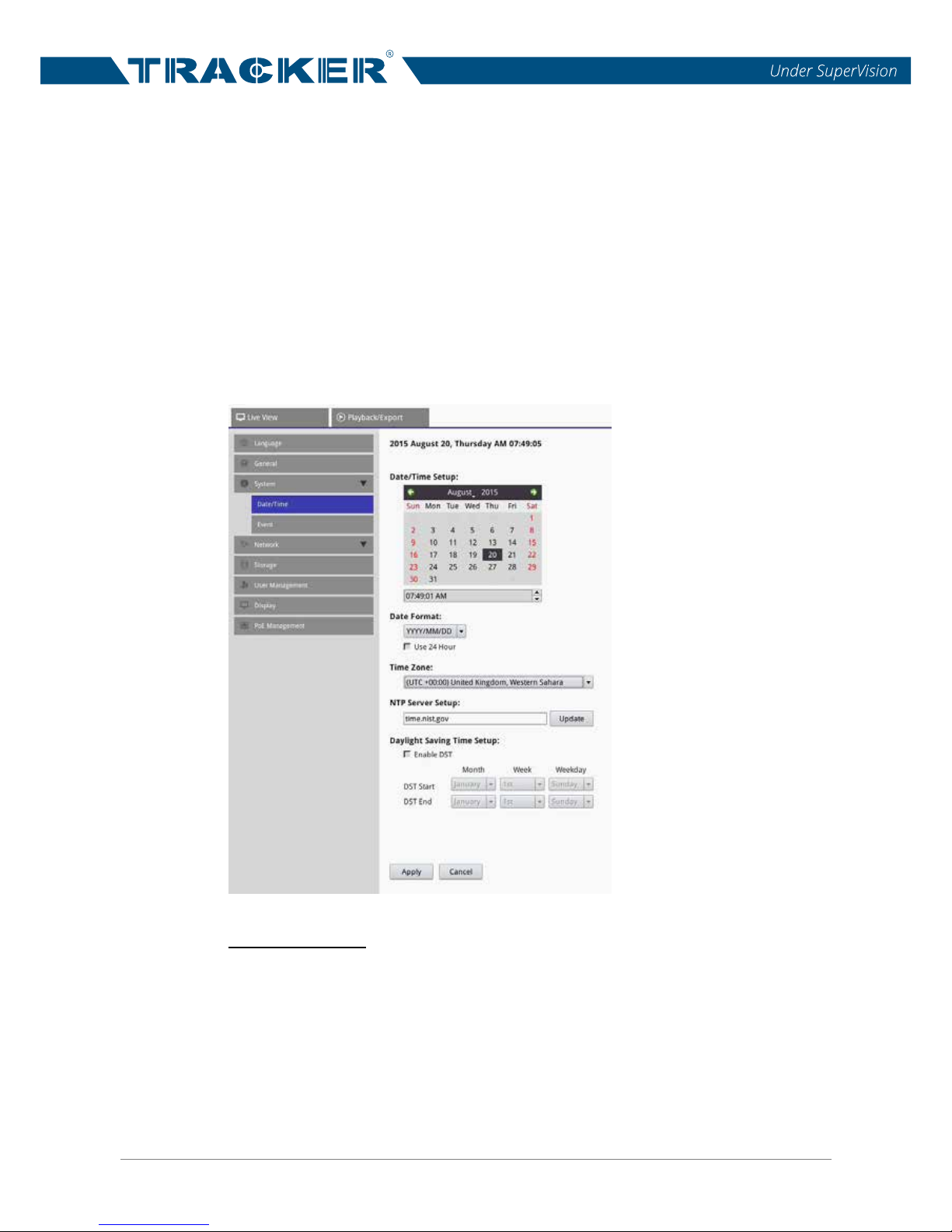
4.2 System Setup
Under System menu, users are able to configure the NVR system settings,
such as date/time, network, user account management, PoE management,
etc. Refer to the following for further description of each function.
4.2.1 Date/Time Setup
Users can set the current date, time and other OSD parameters in Date/Time
setting menu. Enter the Date/Time setting menu via <Setup> <System>
<Date/Time>. The setting menu displays as follows.
Date/Time Setup
To set a date, click and select a date from the calendar and click on <Apply>
to save and apply the setting.
To set up time, click at the target position in the time field and click on the
UP/DOWN arrow buttons or scroll the mouse wheel to change the value in
the selected field.
Page 24
NVR User’s Manual
23
Date Format
This item allows users to set the display type of the date. There are four
options to select from: <YYYY/MM/DD>, <YYYY/DD/MM>, <MM/DD/YYYY>
or <DD/MM/YYYY>. “Y” represents “Year”, “M” represents “Month” and “D”
represents “Day”.
After setting, click on <Apply> to save and apply the setting.
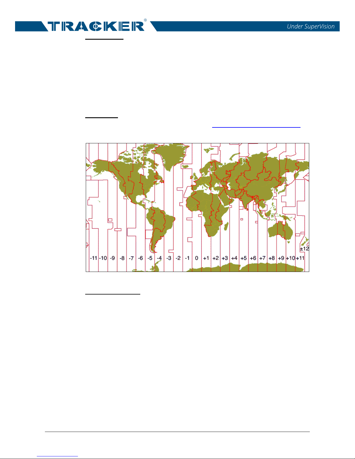
Time Zone
Select users’ current time zone. Please visit www.greenwichmeantime.com to
find out the correct local time zone, or refer to the following figure.
NTP Server Setup
After time zone is selected, users can further setup the NTP (Network Time
Protocol) sever. The default NTP server is time.nist.gov. Users can always
change to any other NTP servers. A list of IP addresses of the NTP servers is
listed below.
129.6.15.28
129.6.15.29
132.163.4.101
132.163.4.102
132.163.4.103
128.138.140.44
192.43.244.18
131.107.1.10
69.25.96.13
206.246.118.250
208.184.49.9
64.125.78.85
207.200.81.113
64.236.96.53
68.216.79.113
After the time server is set, click on <Update> next to the server filed to
synchronize the time immediately.
Page 25
NVR User’s Manual
24
Daylight Saving Time Setup
This is for people who live in certain regions to observe Daylight Saving Time.
Check or un-check the “Enable DST” box to enable or disable this function. If
the function is disabled, the DST Start/End time will be grayed out and cannot
be accessed.
DST Start & End
These items are used to program the daylight saving duration. Click on
the Month / Week / Weekday drop-down list to change the value.
After setting, click on <Apply> to save and apply the setting.
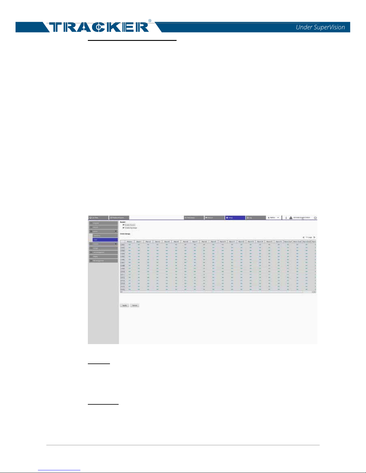
4.2.2 Event Setup
Users can set the event settings for each selected IP camera. Access the
Event setting menu via <Setup> <System> <Event>. The setting menu
displays as follows.
Buzzer
Check the “Enable Buzzer” box, and the NVR will start beeping when motion
is detected or an alarm is triggered.
Key Beep
Check the “Enable key beeps” box, and when users press any control key on
the remote control, the NVR will beep.
Page 26

NVR User’s Manual
25
Motion
This item allows users to enable or disable motion detection function of the
NVR. Click on the corresponding grid to enable ( ) or disable ( ) motion
detection alarm. If motion detection is enabled, it is required to define motion
detection parameters such as detection area and sensitivity settings in the
Camera Motion Setup Pane in Live View tab. Refer to the previous
subsection for more details.
Alarm1 ~ Alarm* (Alarm In)
This item allows users to enable or disable alarm input detection.
Alarm Out
This item allows users to enable or disable the alarm output. The signal can
be a light or a siren to caution the happening of an alarm event. Click on the
corresponding grid to enable or disable the alarm output.
Click on <Apply> to save and apply the setting; otherwise, click on <Cancel>
to abort.
Page 27
NVR User’s Manual
26
4.3 Network Setup
The Network setup menu allows users to specify the network-related settings,
such as IP address and Subnet mask, etc. Check with the network
administrator and/or network service provider for more specific information.
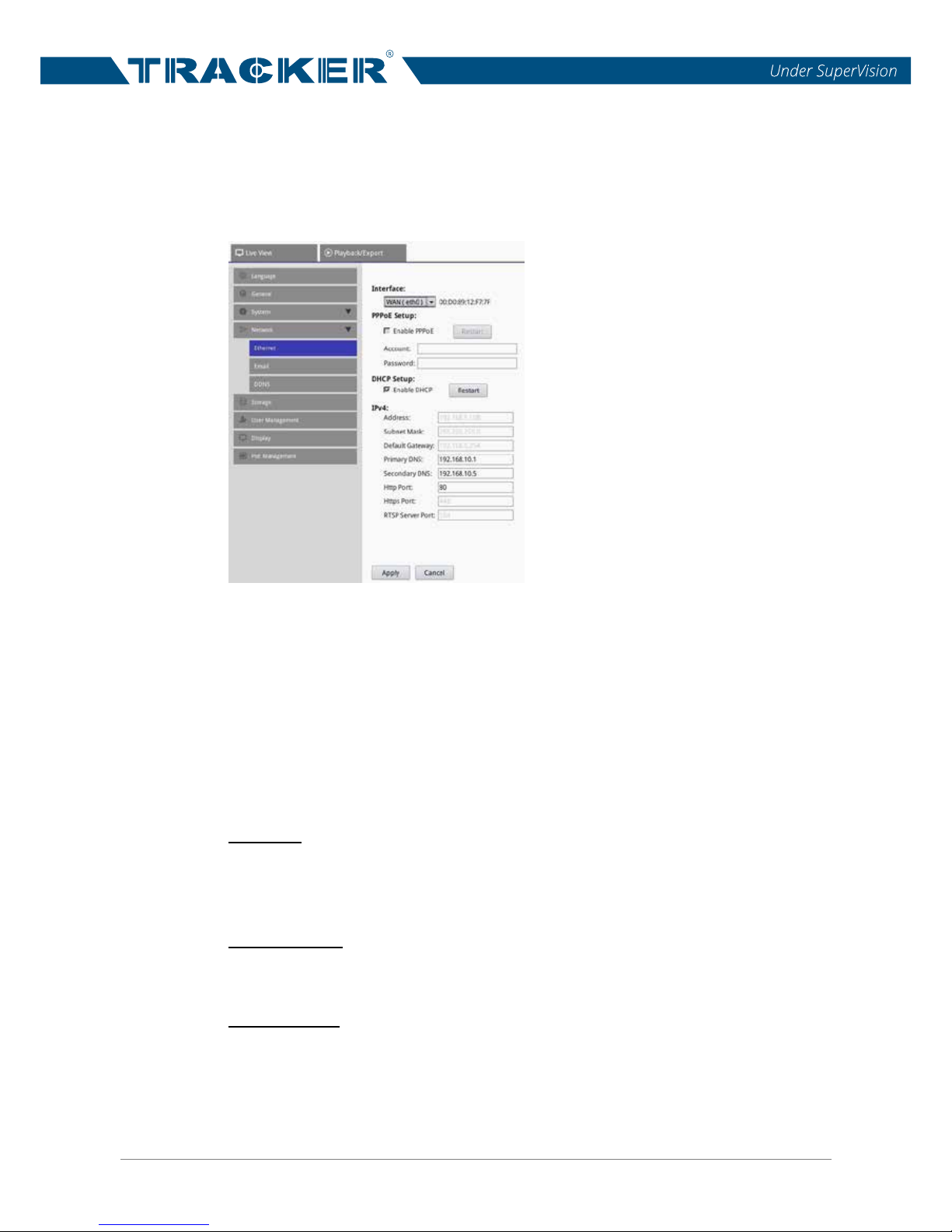
4.3.1 Ethernet Setup
Under this setup menu, users can select the network service type, including
<PPPoE> and <LAN>. If users are using a broadband medium, such as DSL
Line or cable modem, please complete the PPPoE setting. If users are to use
a wired local area network communication, please complete the LAN setting
(IPv4).
Interface
Select <WAN( eth0)> to enter WAN configuration menu. Select <PoE( eth1)>
to enter PoE menu. Select <LAN (eth2)> to enter LAN configuration menu.
MAC Address
This item shows the MAC address of the selected interface.
PPPoE Setup
To setup the PPPoE setting, first check the “Enable PPPoE” box. Then, input
the login username and its corresponding password to the Account and
Password entry fields. Lastly, click on <Restart> next to <Enable PPPoE> to
apply the setting. At last, click on <Apply> to save the configuration.
Page 28

NVR User’s Manual
27
NOTE: <PPPoE Setup> is only available under <WAN (eth0)>
configuration menu.
DHCP Setup
With DHCP function, users are able to obtain a dynamic IP address from
DHCP (Dynamic Host Configuration Protocol) server when the NVR boots up.
When using DHCP, the settings are dynamic and will change every time the
NVR powers on or off, depending on the network setup.
Check the “Enable DHCP” box and click on <Restart>, a dynamic IP address
will be assigned to the NVR. In this case, users do not need to set the
Ethernet settings in IPv4 section, including IP address, Subnet Mask, Defa
ult
Gateway, and DNS settings. These settings will be read-only.
If the NVR is using a fixed address, un-check the “Enable DHCP” box to
manually set IP Address, Subnet Mask, Default Gateway, and DNS. See the
network system administrators or IT personnel for appropriate values.
IPv4
If users decide to set a fixed IP address for the NVR, users have to manually
set the Ethernet settings of the NVR in this section.
- Address
This item is used to configure the IP (Internet Protocol) address of the
NVR. The IP address is the identifier for the NVR on a TCP/IP LAN.
Double click on the entry field and a virtual numeric keypad will pop up.
Enter the static IP address for the NVR using the virtual keypad.
- Subnet Mask
A netmask, a 32-bit mask, is used to divide an IP address into
subnets
and specify the networks available hosts. Its value is defined by the
network administrator. It takes the form as ***.***.***.***, for example,
255.255.255.255. Double click on the entry field and a virtual numeric
keypad will pop up. Enter the value of the subnet mask for the NVR using
the virtual keypad.
Page 29

NVR User’s Manual
28
- Default Gateway
Gateway is a node on a network that serves as an entrance to another
network. Users are allowed to specify the IP address of the gateway or
router associated with this NVR.
- Primary DNS & Secondary DNS
Users can specify the IP address of the Domain Name System associated
with the NVR. If the server is unavailable when using DHCP, the NVR will
search for the network server and boot up more slowly. This network
search continues until it times out.
- Http Port
To avoid the de
fault service port (port 80) being jammed, this item enables
users to change port 80 to another port. To change the web port, double
click on the entry field and enter a value using the pop-up virtual numeric
keypad.
- Https Port
The default setting of Https port is 443. Currently, this item is information
only and cannot be modified.
- RTSP Server Port
The default setting of RTSP Server port is 554. Currently, this item is
information only and cannot be modified.
Users
must click on <Apply> after finishing all the Ethernet settings.
Otherwise, the setting will not be applied and saved.
Page 30
NVR User’s Manual
29
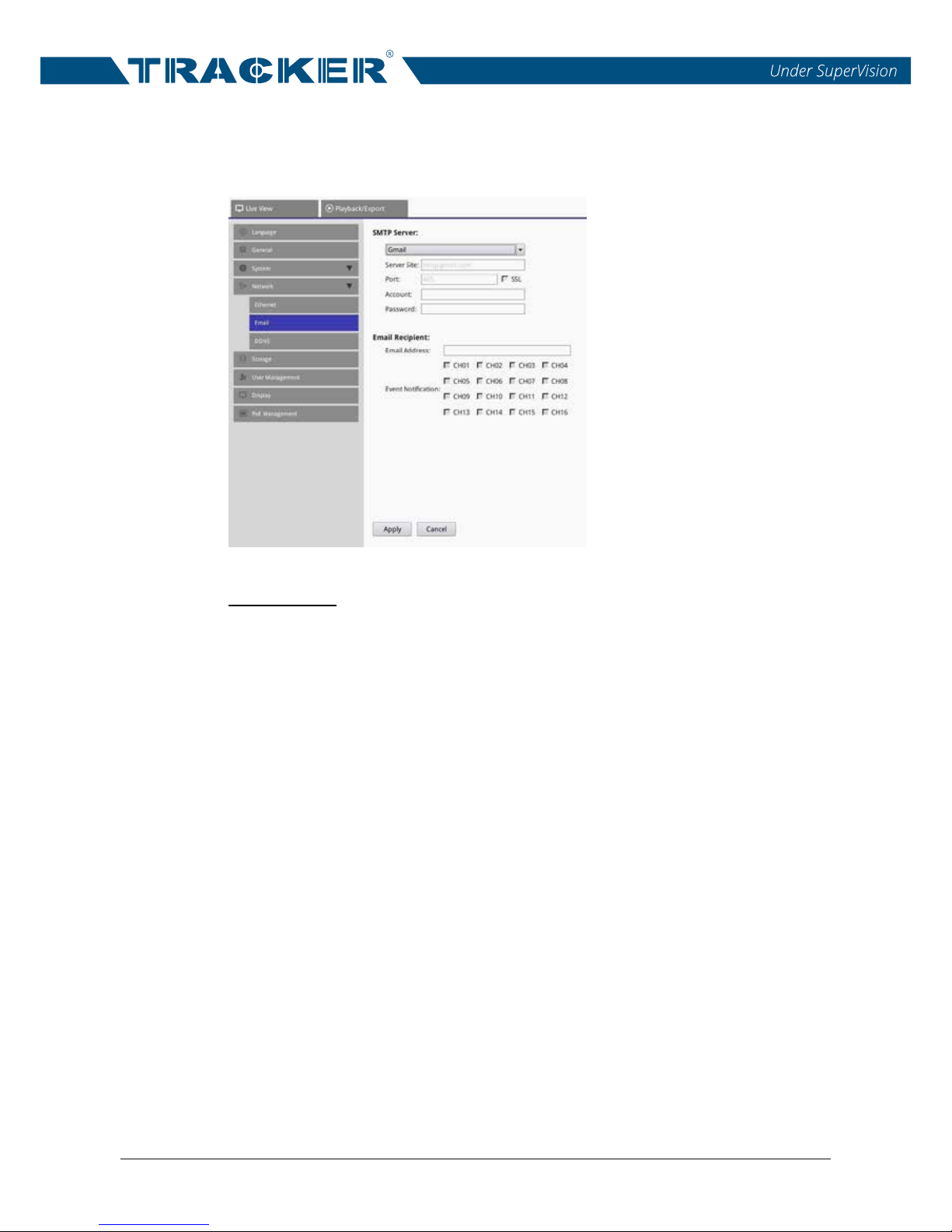
4.3.2 Email Setup
Users can define the e-mail for receiving event/alarm notices.
SMTP Server
Users can select which SMTP server to use. The provided options are
<Gmail>, <Yahoo Mail> and <Custom>.
- Server Site
Those who select <Gmail> or <Yahoo Mail> for the SMTP server, the
NVR will automatically retrieve the server site of either SMTP server. Thus,
this item will be grayed out and cannot be accessed. However, if users
select <Custom>, users must manually input the SMTP server site to the
entry field.
- Port
This item is used to change SMTP port to another port. SM
TP usually is
implemented to operate over Internet port 25.
- SSL
SSL stands for Secure Sockets Layer, which provides communications
security over the Internet. Check the box to enable SSL connection;
otherwise, un-check the box to disable SSL connection. The default SSL
setting is enabled.
Page 31

NVR User’s Manual
30
- Account
Users can setup the SMTP username. Double click on the entry field and
a virtual keyboard will pop up. Enter the desired e-mail account, usually a
full e-mail address, when complete, click on <OK> to close the virtual
keyboard.
- Password
Users should enter the corresponding password of the account inserted in
Account field above.
Email Recipient
This item is used to edit the e-mail address where event / alarm notification
will be sent. Refer to the following to setup all the required information.
- Email Address
Enter the e-mail address where event/alarm notifications will be sent.
Double click on the entry filed and enter the e-mail address using the
pop-up virtual keyboard. Click on <OK> from the keyboard to complete
the setting.
- Event Notification
Users can select the event/alarm from which channel to be sent
to the
e-mail address previously set. Click to check or un-check the channel box
to select / de-select the channel.
Users must click on <Apply> after modifying the settings. Otherwise, the
setting will not be applied and saved.
Page 32
NVR User’s Manual
31
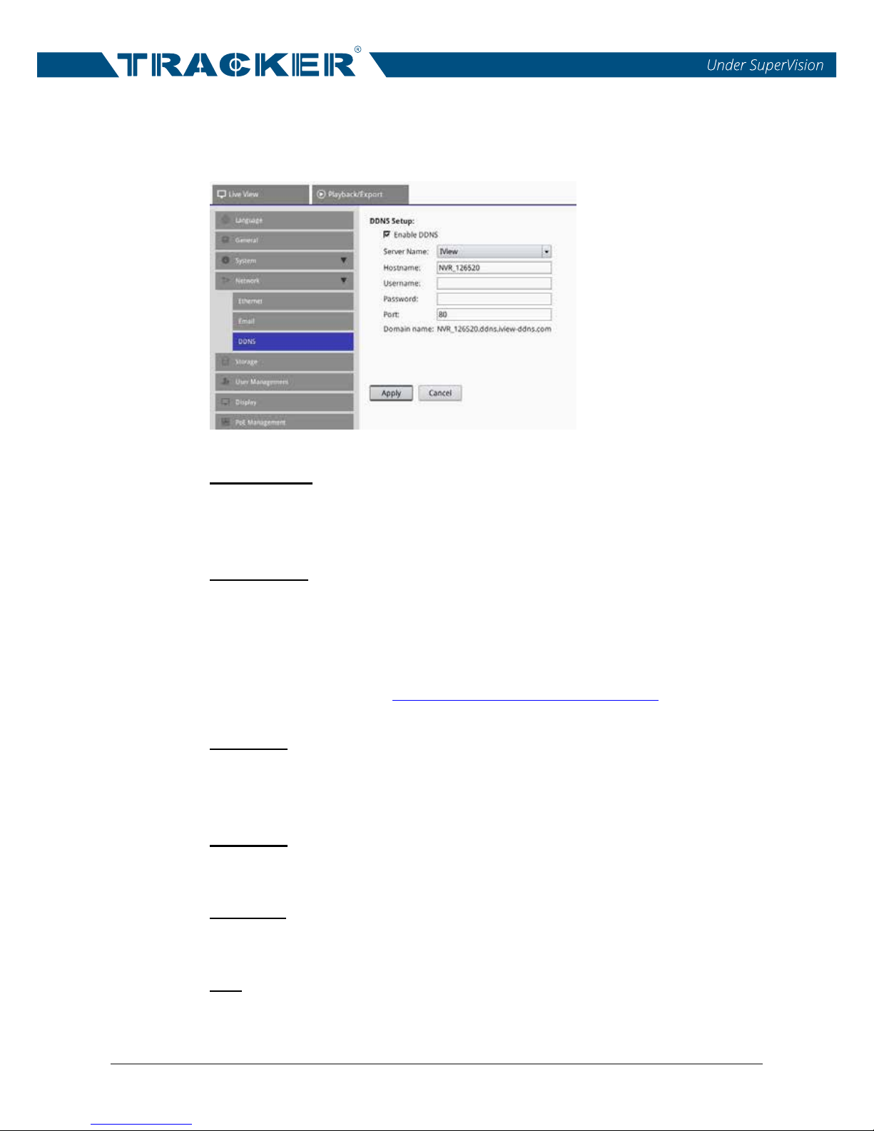
4.3.3 DDNS Setup
Select <DDNS Setup> from Network. The menu displays as below.
Enable DDNS
The item is used to enable or disable the Dynamic Domain Name Service.
Click to check or un-check to enable or disable the service.
Server Name
This item is for users to choose the service provider. The current option is
<IView> (ivew-ddns) only.
After users further setup and save the preferred <Hostname> and <Port>, the
DDNS address will be as http://hostname.ddns.iview-ddns.com.
Hostname
The item allows users to setup a domain name, which is used for entering the
NVR through internet on the remote PC.
Username
Enter the valid DDNS username here.
Password
Enter the corresponding DDNS user password here.
Port
Users can setup the port for DDNS.
Page 33

NVR User’s Manual
32
Domain name
After submitting the setting, the domain name of the NVR will be displayed
here as information.
Users must click on <Apply> after finishing the settings. Otherwise, the
settings will not be applied and saved.
Page 34
NVR User’s Manual
33
4.4 Storage Setup
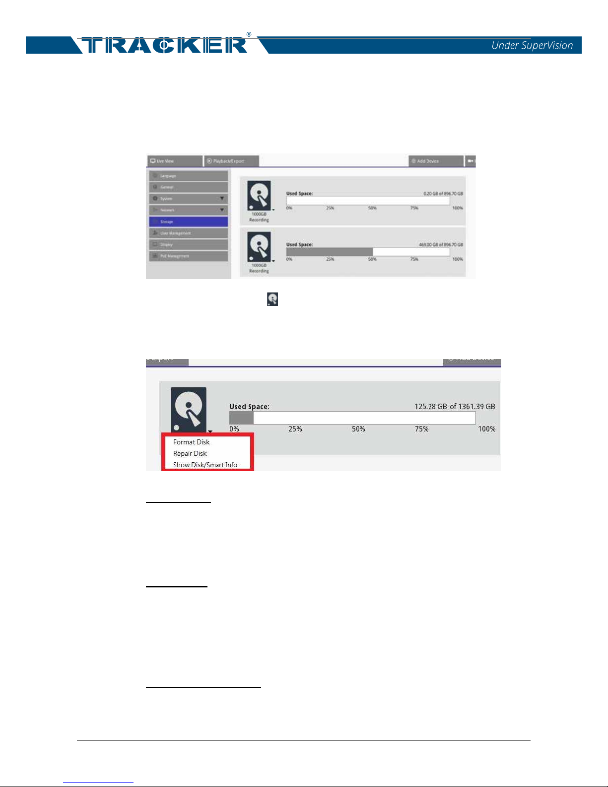
The Storage Setup menu allows users to check the detailed information of
the internal HDDs, format or repair the internal HDDs. Also, users can check
the basic information and S.M.A.R.T information of the selected HDD.
Click on the HDD icon < > and a drop-down list will be displayed as below.
The list includes three options, <Format Disk>, <Repair Disk> and <Show
Disk/Smart Info>.
Format Disk
If needed, users can format the selected HDD by selecting this item. Click on
this item and a warning window will pop up. Click on <OK> to start the HDD
format procedure, or click on <Cancel> to abort the HDD format procedure.
Repair Disk
If there is error found on the selected disk, execute this function to try to
repair the HDD. Select this item and a warning window will pop up. Select
<OK> to begin the repair procedure, or click on <Cancel> to abort the repair
procedure.
Show Disk/Smart Info
Select this item, and users can view and check the brief information and
S.M.A.R.T information of the selected internal disks.
Page 35
NVR User’s Manual
34
4.5 User Management Setup
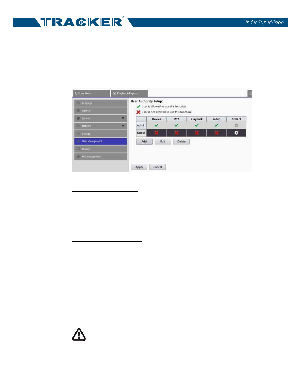
The NVR provides the option to create up to six user accounts with
customized authority, excluding the preset “Admin” and “Guest” accounts.
Access the User Management setting menu via <Setup> <User
Management>. The setting menu displays as follows.
Add a New User Account
Follow the steps below to create and add a user account.
Click on <Add> and a setting window will show up.
Input the desired username and its password to set a user account.
Then, click on <ok> to complete and save the setting..
Setup/Edit a User Account
Follow the steps below to setup a user account.
Select a user account and click on <Edit> to enter User Information
setting window.
Edit the username, password and event add/remove an avatar for the
selected account in the User Information setting window. Note that the
image resolution of the avatar must be less than 720 x 480.
After setting, click on <ok> to save and apply the modified settings.
To delete a user account, select the desired user account and click on
<Delete>.
NOTE: The preset “Admin” account and “Guest” account both cannot
be deleted. In addition, users can only modify the password and avatar
of “Admin” and the avatar of “Guest”.
Page 36
NVR User’s Manual
35
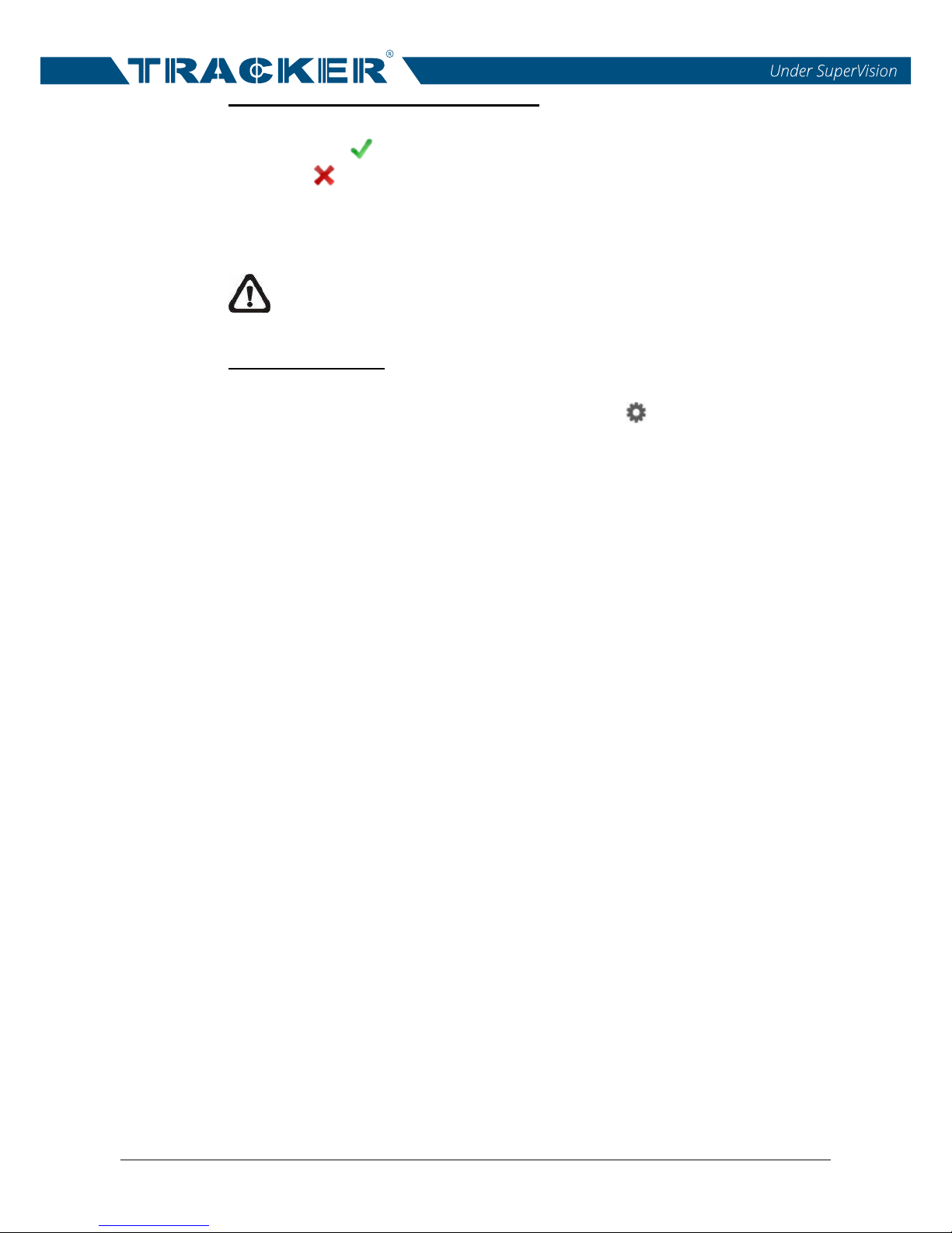
Setup User Permissions (Authorities)
Set the permissions to access the functions listed in the User Management
setting menu. < > represents the user account is authorized to access the
function. < > represents the user account is not granted to access the
function. Click on the function item to allow or not allow the access from the
selected user.
NOTE: The preset account “Guest” can only view the live viewing
under the Live View and access the Playback/Export function tab.
Covert IP Cameras
Users can decide which channels to be seen or hidden when certain user
accounts log in. Click on the Covert Setting icon < > corresponding to the
desired user account to enter the setting menu.
To hide the channel view, un-check the channel box. To display the view of
the channel, check the channel box. Users can click on <Select All> to check
or un-check all channels. Then, click on <Ok> to save and apply the setting;
otherwise, click on <Cancel> to abort.
Page 37
NVR User’s Manual
36
4.6 Display Setup
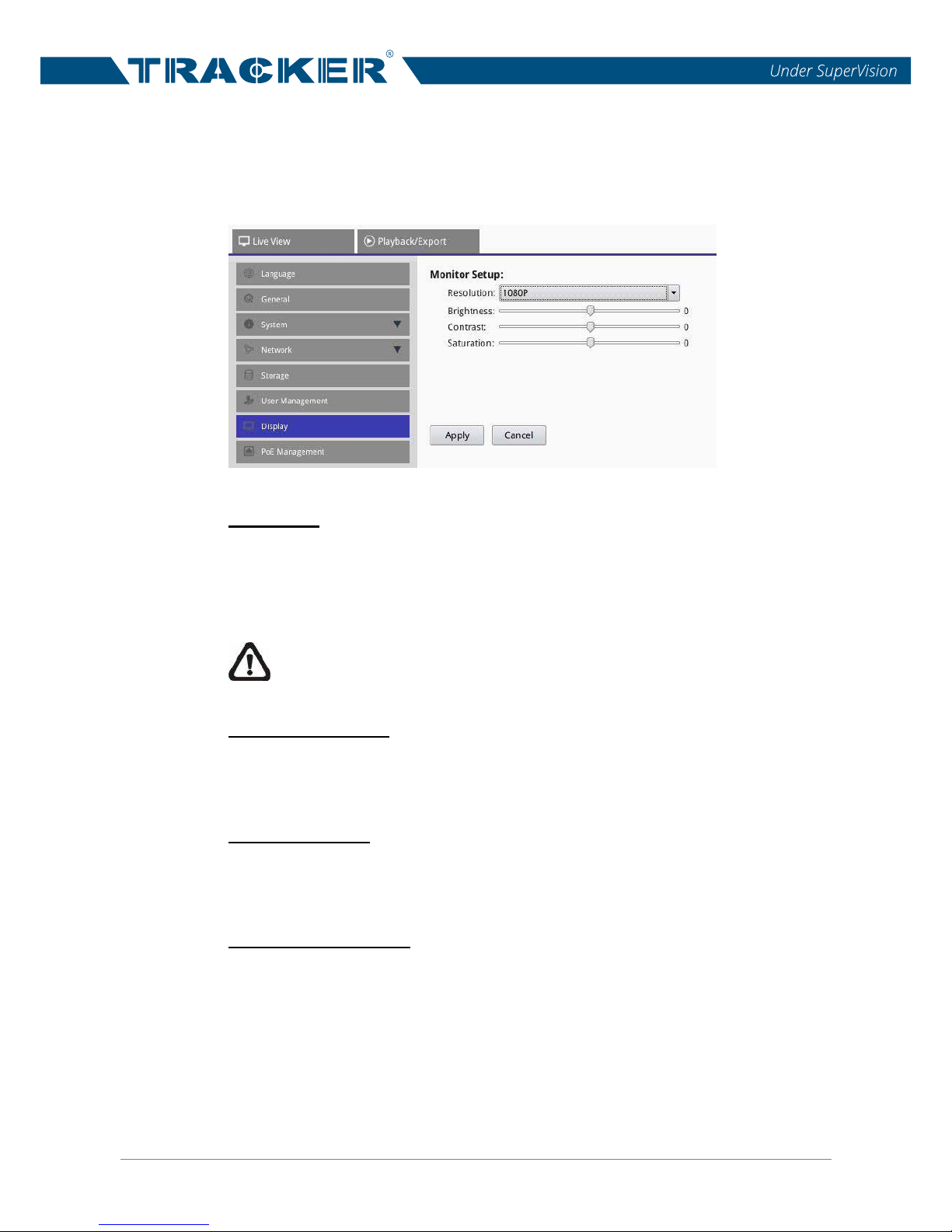
The Monitor setup menu allows users to adjust the quality of the displayed
image.
Resolution
This item allows users to select appropriate resolution for the monitor
connected to the NVR. The options are <1024x768>, <1280x1024>, <720P>
and <1080P>.
NOTE: After the resolution setting is altered and applied, the system
will ask users to reboot for applying the change.
Monitor Brightness
This item is for users to adjust the brightness of the monitor. Click and drag
the scroll to adjust the value. The setting value ranges from <-32> to <31>.
Monitor Contrast
This item is used to adjust the color contrast of the monitor. Click and drag
the scroll to adjust the value. The setting value ranges from <-32> to <31>.
Monitor Chrominance
This item can be used to adjust the chrominance of the monitor. Click and
drag the scroll to adjust the value. The setting value ranges from <-32> to
<31>.
Users must click on <Apply> after setting. Otherwise, the setting will not be
applied and saved.
Page 38
NVR User’s Manual
37
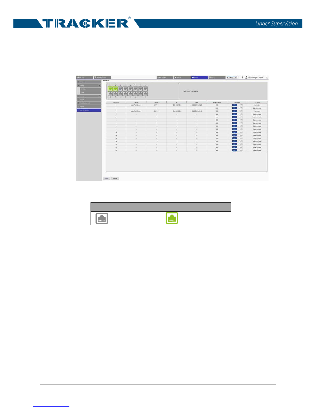
4.7 PoE Management
Under this setting menu, users can check each PoE port’s status and
manage PoE ports. Select <PoE Management> under Setup function tab to
enter its setting menu.
PoE Port Connection Status Icon:
Icon
PoE Status
Icon
PoE Status
No Connection
Successful
Connection
Total Power Output:
Uses can check the total power consumption of the connected IP cameras
here. The maximum power consumption is also listed here.
RJ45 Port
This item lists the number of PoE port.
Name
This item lists the name of the IP camera
Model
This item shows the model name of the IP camera.
IP
Here lists the IP address of the IP camera, which is assigned by the NVR.
Refer to the following sections for further information of IP address setup.
Page 39

NVR User’s Manual
38
MAC
The MAC address of the IP camera lists here.
Power(Watt)
The power consumption of the PoE port can be checked here.
PoE Power
Select <ON> to enable power supply to the connected IP camera. Select
<OFF> to stop supplying power to the PoE port, and the PoE port will just be
network connection port.
Click on <Apply> to save the setting.
PoE Status
Users can check if the PoE port is connected with an IP camera or not.
NOTE: Users MUST make sure that DHCP function of the IP cameras
to be connected to the PoE p
ort is disabled; otherwise, the IP camera
connection will be failed.
Page 40
NVR User’s Manual
39
5. Add Device (IP Camera Connection)
The Add Device setup menu is for users to search and connect the IP
cameras either via direct PoE connection or through network connection to
the NVR. Refer to the following for further description of connecting an IP
camera to the NVR.
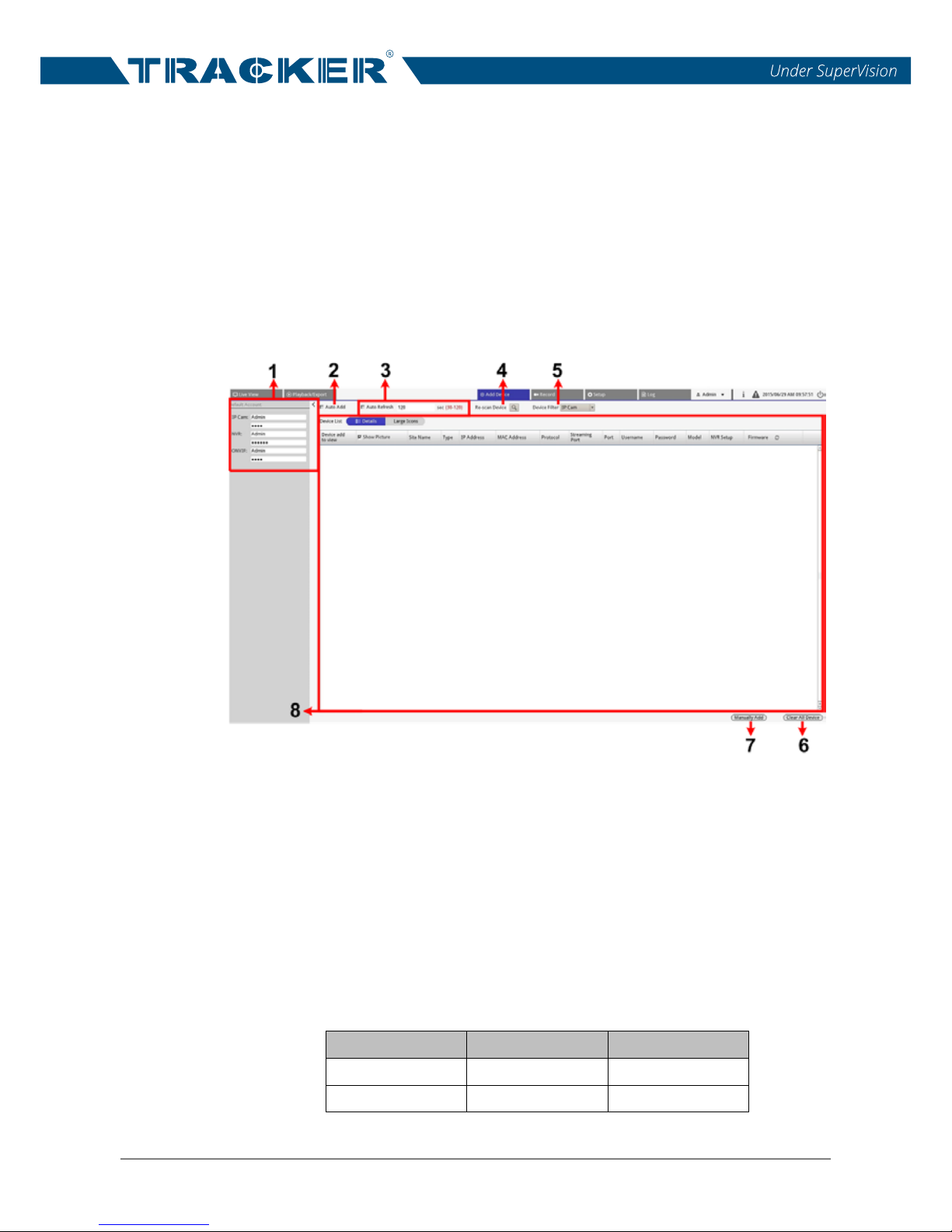
5.1 Add Device Window
The following introduces each function item in the Add Device setup menu.
1. Default Account Pane
Users can preset the default username and password for each type of IP
camera
s. Once an IP camera is
connected to the NVR, the NVR will
automatically apply the preset username and password to the IP camera
according to its model type.
Users can modify the default account name and the password. The
following lists the account names and passwords of each type of IP
cameras.
Camera Type
Account Name
Password
IP Camera
admin
admin
ONVIF admin admin
Page 41

NVR User’s Manual
40
2. Auto Add
This function allows the NVR system to automatically re-search and add
the newly found IP cameras to the NVR. When this function is enabled,
Auto Refresh function will simultaneously be enabled.
Check the “Auto Add” box, and Auto Add function will be enabled. Next,
set the Auto Refresh time interval.
Note that if the NVR has already added 24 IP cameras, the NVR will not
add any newly found IP cameras.
3. Auto Refresh
Check this box and the NVR system will automatically re
fresh the Device
List by every N seconds. The time duration “N” ranges from 30 to 120
seconds.
4. Re-scan Device
Click on the icon; the NVR will begin searching the IP cameras installed in
the same LAN as the NVR that meet the searching criteria in the Device
List.
5. Device Filter
Device Filter is for users to select the type of the IP camera models to be
searched during device search.
6. Clear All Device
Click on <Clear All Device> at the bottom-right corner of the monitor, and
the NVR will disco
nnect all connected IP cameras, excluding the IP
cameras that are connected via PoE ports.
7. Manually Add
Aside from device search, users can manually add an IP camera to the
NVR. Click on <Manually Add>; a blank new device column will be added
to the Device List. Input the essential information of a known IP camera to
the corresponding fields, including <Type>, <IP Address>, <Protocol>,
<Streaming Port>, <User Name> and <Password>. Then, check the
“Device add to view” box, and the NVR will start to
connect the IP camera.
To delete the manually added IP cameras, click on the delete icon < >,
and the IP camera will be removed from the Device List.
Page 42

NVR User’s Manual
41
8. Device List
After the device search, the NVR will list the IP cameras installed in the
same LAN that meet the searching criteria in the Device List. Users can
check the brief information of the found IP cameras in Device List, such as
MAC address, IP address, model type, username/password, etc.
Under Device List, <Details> and <Large Icons> are provided for users to
switch views. Select <Details>, and the information of the IP cameras will
be listed in columns and users can view the prev
iew of the IP camera.
Select <Large Icons>, and users can check and view the brief information
of the IP cameras and its preview. Note that when the preview grid of an
IP camera shows “Not Supported” or “No Snapshot”, this suggests the IP
camera does not support this function.
When an IP camera is directly connected via PoE port, “(PoE0N)” will be
added to the end of the Site Name, e.g. “MegaPixelCamera(PoE03)”,
which means this IP camera is connected via the third PoE port.
Page 43
NVR User’s Manual
42
5.2 IP Camera Connection
Users are able to connect an IP camera either through network connection or
via PnP function. Note that PnP function is only for models with PoE ports.
The following describes how to connect an IP camera via network connection
or via PnP function
Add IP Cameras via PnP Function (Models with PoE Ports Only)
When users connect the IP cameras to the PoE ports on the NVR’s rear
panel, the IP camera will automatically be powered up and connected to the
network. The NVR will automatically assign an IP address for the IP camera.
The following describes the rules of the IP address of the IP camera.
192.168.(50+Port Number).(25~99)
For instance, the IP address of PoE port 8 would be like “192.168.58.33”.
The fourth set of the IP address is limited within a specified range, from 25 to
99. When an IP camera is connected to the PoE port, the NVR will
automatically assign the fourth set a random number within the limited range.
If users wish to access the IP camera connected to the PoE port via a web
browser, just enter the IP address of the NVR plus a colon and a number
(8000 + port number of the desir
ed IP camera). Take CH4 for example, if the
IP address of the NVR is 192.168.0.50, the IP address of CH4 will be
192.168.0.50:8004.
NOTE: Users MUST make sure that DHCP function of the IP cameras
to be connected to the PoE port is disabled; otherwise, the IP camera
connection will be failed.
Add IP Cameras via Network Connection
Follow the steps below to search and add IP cameras to the NVR via
network.
Select the type of IP camera models next to <Device Filter>.
Click on the Search icon. The NVR will start to look for the supported IP
cameras installed in the same LAN and list them in the Device List.
Find a target IP camera from the Device List and check the “Device add to
view” box to add the IP camera to the NVR. The NVR will automatically
connect and retrieve the information of the IP camera.
Page 44
NVR User’s Manual
43
6 Record
The Record setup menu allows users to set recording schedules. The
following describes how to setup the recording schedule and event settings of
each connected IP camera.
NOTE: Please refer to the previous section for Event Setup.
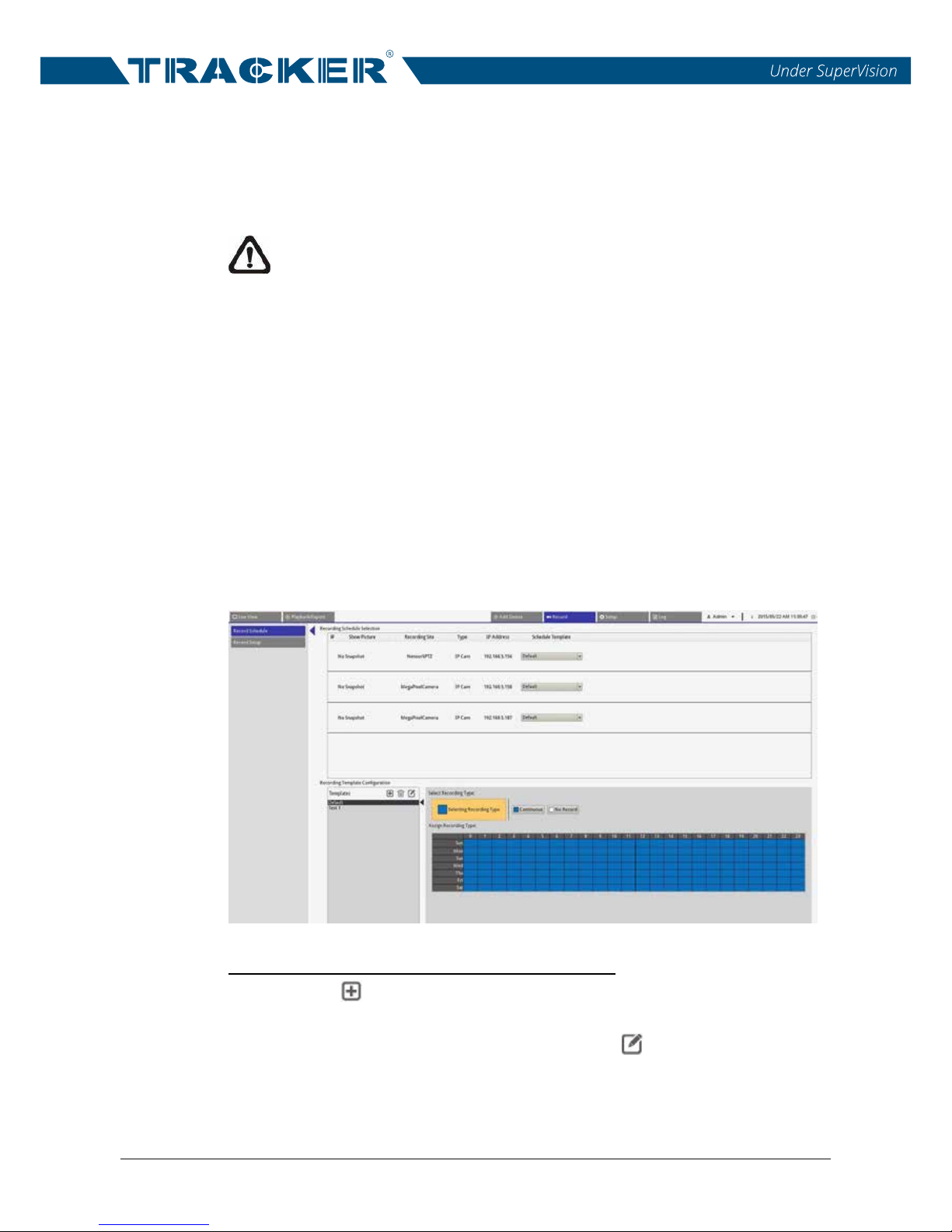
6.1 Record Schedule Setup
Record Schedule setup menu allows users to setup recording templates and
assign recording type for days in a week by hours for each recording
templates.
Two record types are provided, <Continuous> and <No Record>.
<Continuous> indicates that the NVR will keep recording in the specified time
segment. <No Record> represents the NVR will not record and save any
video data in the specified time segment. Refer to the following to setup a
recording template.
Add / Remove / Rename a Recording Template
Click on < > in the Recording Template Configuration pane. A new
template will be added to the template list.
Then, select the added template and click on < > or double click on the
selected template in the template list.
Input the desired name in the name field to revise the name of the
template.
Page 45
NVR User’s Manual
44
Click on <OK> from the virtual keyboard to apply the setting.
To delete a recording template, select a recording template and then click
on < >. The selected recording template will be removed from the
template list.
Setup a Recording Template
Follow the steps below to setup a recording template.
Select a recording template from the template list.
Click on a desired recording type, <Continuous> or <No Record>.
Click at any grid of time to assign the selected recording type.
Click on any hour on the top to fill up the column.
Click on any day on the left to fill up the roll.
Click on the top left grid to always record with the selected recording type.
Click and drag the mouse to fill up and assign the selecte
d recording type.
Assign Recording Template to the Connected IP cameras
Users can assign a preset recording template to each connected site. After
templates are set, select a desired recording template from the drop-down list.
The NVR will record each site according to the applied template.
NOTE: If the applied recording template is removed from the template
list, the system will automatically apply the default template to the site.
6.2 Record Setup
In Record Setup menu, users can setup whether to enable the circular
recording of the NVR and whether to record the pre-alarm / post-alarm video
as a part of event videos when an alarm or event occurs.
Circular Recording
The Circular Recording function is to adjust the HDD space usage of the NVR
and to store new video data while overwriting the oldest recorded video.
Follow the instruction below for circular recording setup.
Check the box to enable circular recording and select <Size> or
<Percentage> to set as the unit of the reserved HDD partition.
Then, set a threshold value (5% or 5120MB) in the entry field. The NVR
will reserve the certain partition of the HDD, and when the used space of
the HDD
reaches the threshold, the NVR will start overwriting the oldest
recorded data.
Page 46

NVR User’s Manual
45
For instance, when the threshold is set to 5GB (5120MB), and there are
20GB free disk space remaining in the HDD, the NVR can only access the
HDD no more than 15GB.
Un-check the “Circular Recording” box, and the NVR will stop recording when
HDD is full.
Alarm Behavior Configuration
Users can setup the pre-alarm / post-alarm video duration to be a part of
event videos.
Check the “Post-Alarm Recording” / “Pre-Alarm Recording” box to enable the
post-alarm / pre-alarm video recording function. Then, input the desired pre-
alarm / post-alarm duration to the entry field. The time duration range is from
5 to 120 seconds. Note that normal video recording MUST be enabled in
order to provide video data to the matching event video.
Page 47
NVR User’s Manual
46
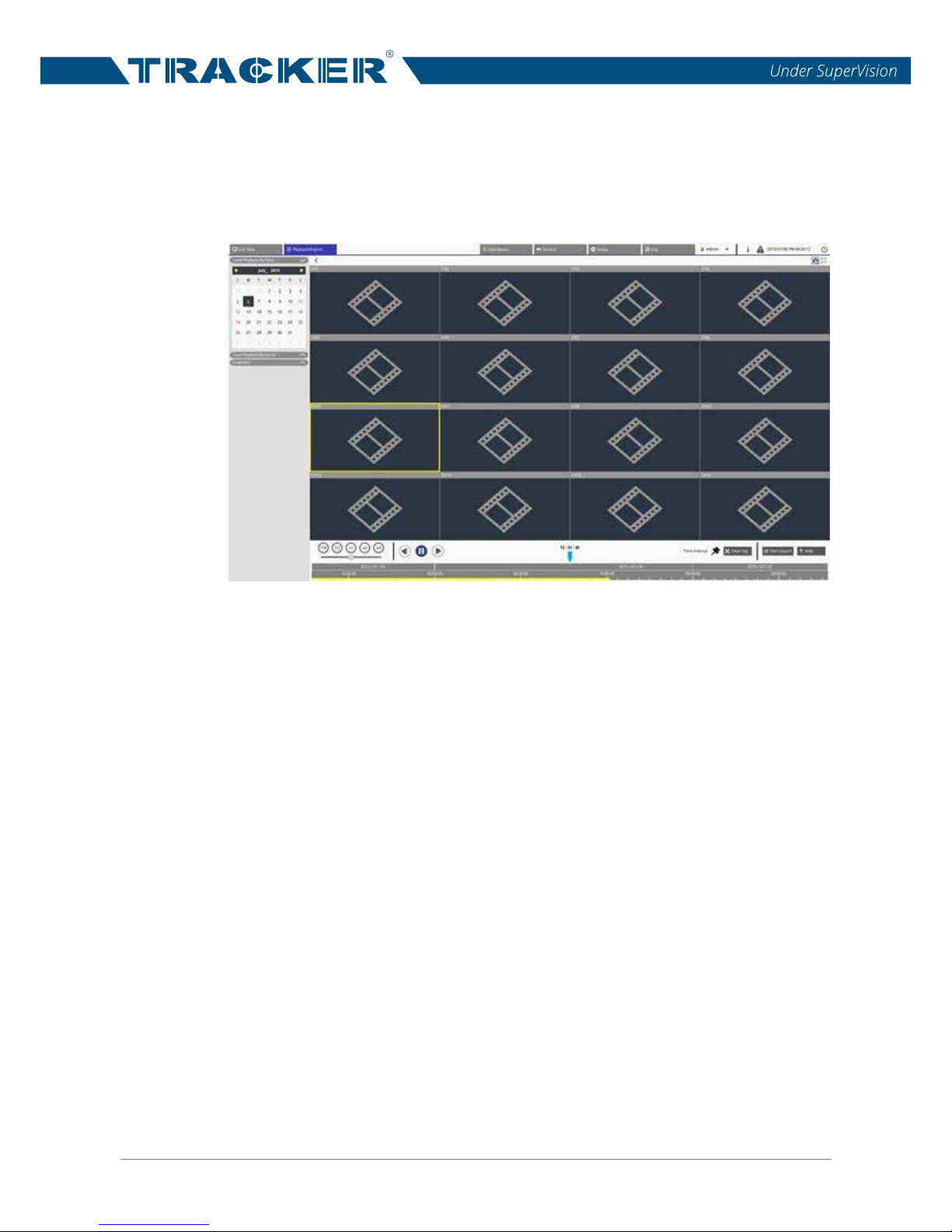
7 Playback/Export
Users can select and playback the recorded videos in the Playback/Export
function tab. Besides, users can view the snapshots and export the desired
videos/snapshots in this function tab.
7.1 Playback Control Bar
Playback control bar is displayed at the bottom of the screen.
Playback Speed
Click and drag the slider control bar to select the speed of backward /
forward, x1/4, x1/2, x1, x2 and x4.
Rewind
Click on this icon to reverse playing back the recorded videos.
Pause
Click on this icon
to pause the playback.
Play
Click on this icon to start playing back the recorded videos.
Page 48
NVR User’s Manual
47
7.2 Search / Playback / Export Normal Videos
The NVR is capable of searching and playing back the recorded videos by
date/time. Refer to the following for further instruction.
Playback Videos by Time
Select any underlined date from the calendar, which indicates the
recording data are available. Then, the yellow stripe in the time bar shows
there are recorded videos for users to playback.
Then, click and drag the time bar to select a preferred time from the time
bar. The selected time will be displayed above the blue indicator.
Move the mouse cursor to the time bar and scroll up/down the mouse
wheel to adjust the time scale to select the exact desired time.
Click on the Playback
icon < > to start playing back the selected video.
Export Normal Videos
Follow the steps below to export the normal videos.
NOTE: Before the video exportation, make sure an external USB
storage device is installed to the NVR. Otherwise, a warning message
will pop up.
Select a preferred underlined date from the calendar. The time bar will
display the available recording data of each channel.
Click and drag the Time Interval icon < > and drop it to the time bar to
select the desired time interval of recorded video.
Use the Time Range Adjustment icon < >
to adjust the preferred time
segment. Scroll up/down the mouse wheel to zoom in/out to adjust and
select the exact desired time.
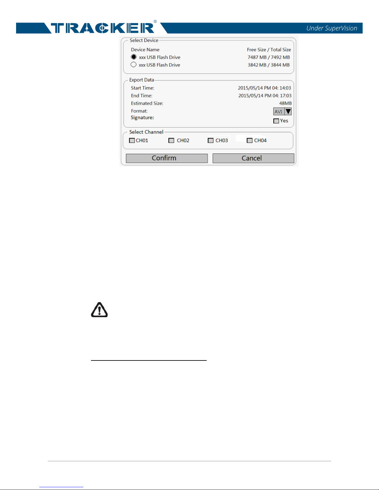
Click on <Start Export>, and an Export window will be displayed.
Check the desired channel(s) and the exportation data including data size
will be shown.
Page 49
NVR User’s Manual
48
Select the desired external device and choose the video format for the
to-be-exported video. The provided video formats include *.avi, *.raw,
*.mp4, *.mkv and *.mov.
Check the desired channel boxes to be exported.
The video can be exported with or without a digital signature. Check the
box to export the video with signature file, or un-check to export without it.
Click <Confirm> in the Export window to start the video exportation.
Alternatively, click <Cancel> to abort.
Af
ter the video exportation is completed, a message window will appear,
click <OK> to close the window.
Click <Close> in the Export window to exit.
NOTE: If digital signature is required, there will be three files be
exported, including *.sig, *.avi(*.raw / *.mp4 / *.mkv / *.mov) and *.gpg.
7.3 Search / Playback / Export Event Videos
Search and Playback Event Videos
Users are able to search events by time, channel, or type. Follow these steps
to search event video.
Click on the Local Playback By Event bar to display the Event Search
Filter.
In the Event Search Filter, check the “Search By Time” box and specify
the Start / End time for the time range of the event search.
Check the “Search By Channel” box to select the desired channels to the
event search.
Page 50
NVR User’s Manual
49
Check the “Search By Type” box and designate which event type to be
included in the event search.
Click on <Search> to list event videos that meet the searching criteria
above.
The Event List displays events by date/time, event type and triggered
camera and is listed in chronological order. Click on < > / < > below
the Event List to go to previous/next page.
Click on any event, and the viewing window on the right will start playing
back the selected event.
Export Event Videos
Follow the steps below to export the event videos.
NOTE: Before the video exportation, make sure an external USB
storage device is installed to the NVR. Otherwise, a warning message
will pop up.
Select a desired event from the Event List.
Click on <Start Export> at the bottom-right corner of the monitor. An
Export window will be displayed. The listed information includes the
exportation data and the available external devices for video exportation.
Select the desired external device an
d choose the video format for the
to-be-exported video. The provided video formats include *.avi, *.raw,
*.mp4, *.mkv and *.mov.
The video can be exported with or without a digital signature. Check the
box to export the video with signature file, or un-check to export without it.
Click <Confirm> in the Export window to start the video exportation.
Alternatively, click <Cancel> to abort.
After the video exportation is completed, a message window will appear,
click <OK> to clo
se the window.
Click <Close> in the Export window to return to the Event Search menu.
NOTE: If digital signature is required, three will files be exported,
including *.sig, *.avi(*.raw / *.mp4 / *.mkv / *.mov) and *.gpg.
Page 51
NVR User’s Manual
50
7.4 View / Export Snapshots
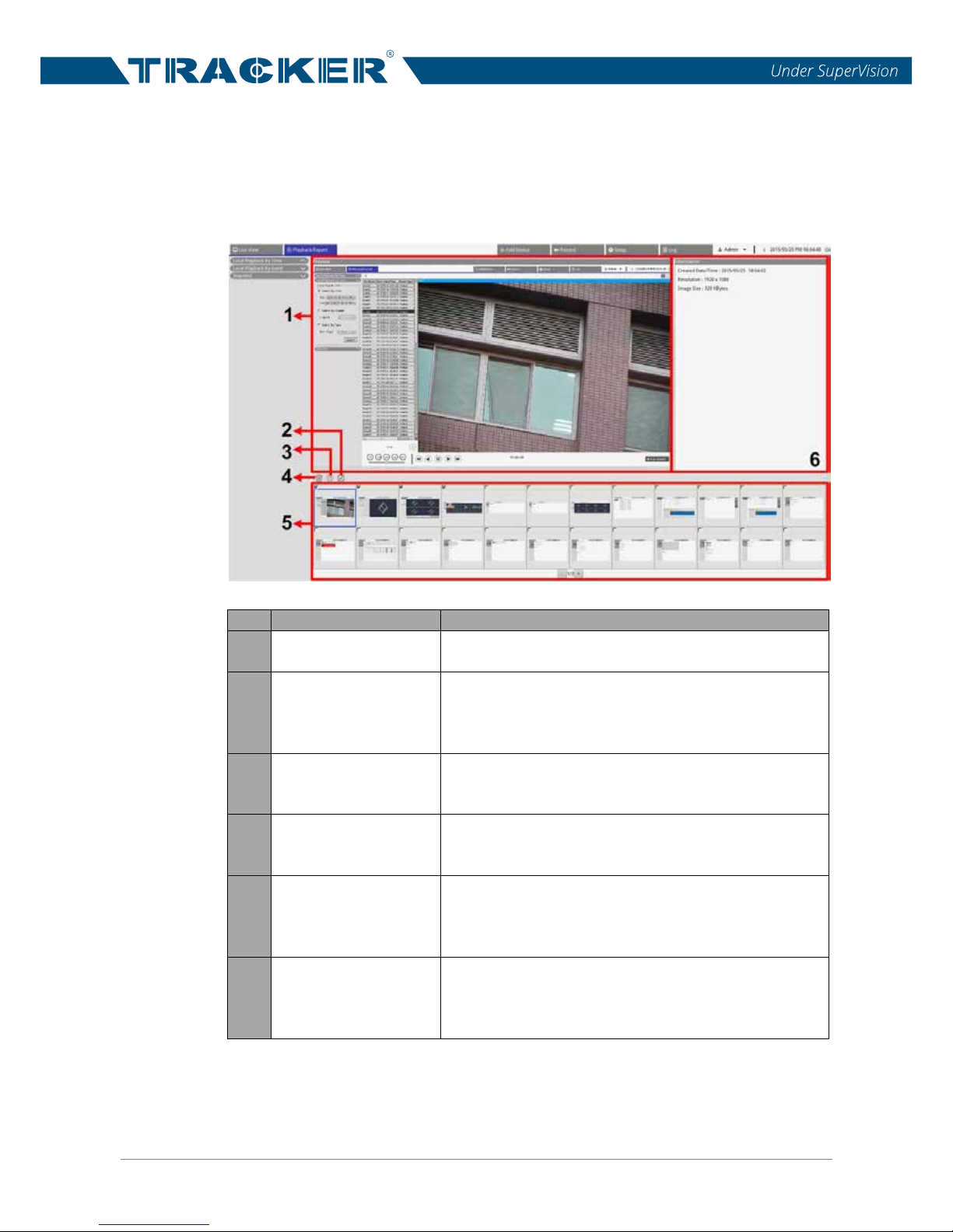
The NVR allows users to capture the current viewing either in Live View or
during the playback. In addition, users can check and export the captured
snapshots in the Playback/Export function tab.
No.
Item
Description
1 Preview Window
Select a snapshot file from the Snapshot List
below, and users can check its preview.
2 Select All
Click on this icon and all snapshots in the
Snapshot List will be selected. Users can then
click on the Export or Delete icons to export or
delete all files.
3 Export
Select a snapshot file(s) and click on this icon,
and users can export the selected snapshot
file(s).
4 Delete
Select a snapshot file(s) from the Snapshot List
and click on this icon; the selected file(s) will be
deleted without notice.
5 Snapshot List
Here lists all the captured images. Users can
click on any thumbnail image to preview the
selected snapshot and its related information in
the Snapshot Information Pane.
6
Snapshot
Information
Select any captured image in the Snapshot List,
and its related information, including the
captured date/time, image resolution and image
size, is listed in this pane.
Page 52
NVR User’s Manual
51
Snapshot Export
Follow the steps below to export captured image(s).
NOTE: Before the video exportation, make sure an external USB
storage device is installed to the NVR.
Check the box of the desired snapshot file from the Snapshot List. Or,
click on < > to select all snapshot files.
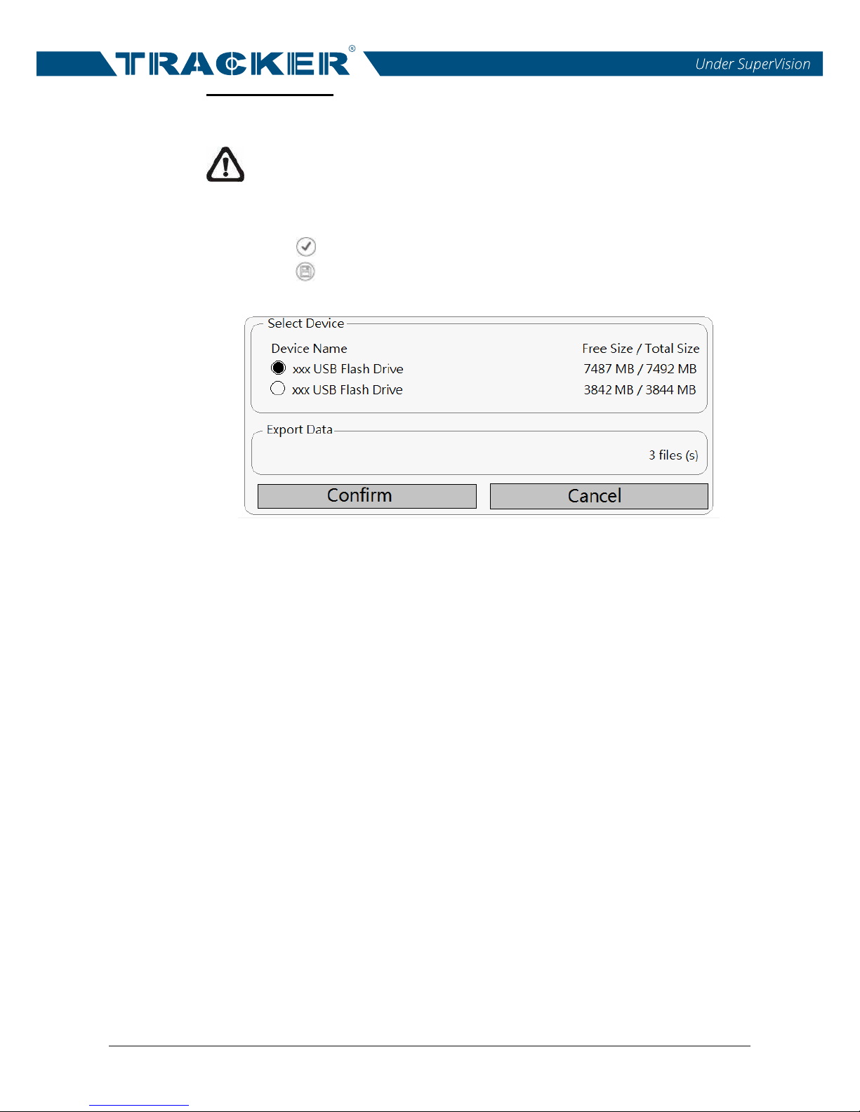
Click on< >, and an Export window will pop up as below.
All connected USB devices will be listed under Select Device, select one
as the file destination. The number of the selected file(s) will be listed
under Export Data.
Click on
<Confirm> to start exporting the files; otherwise, click on
<Cancel> to abort.
Page 53
NVR User’s Manual
52
8 Log
In Log function tab, users can check, view, search and export the log data.
Refer to the followings for further description.
8.1 Search Log Data
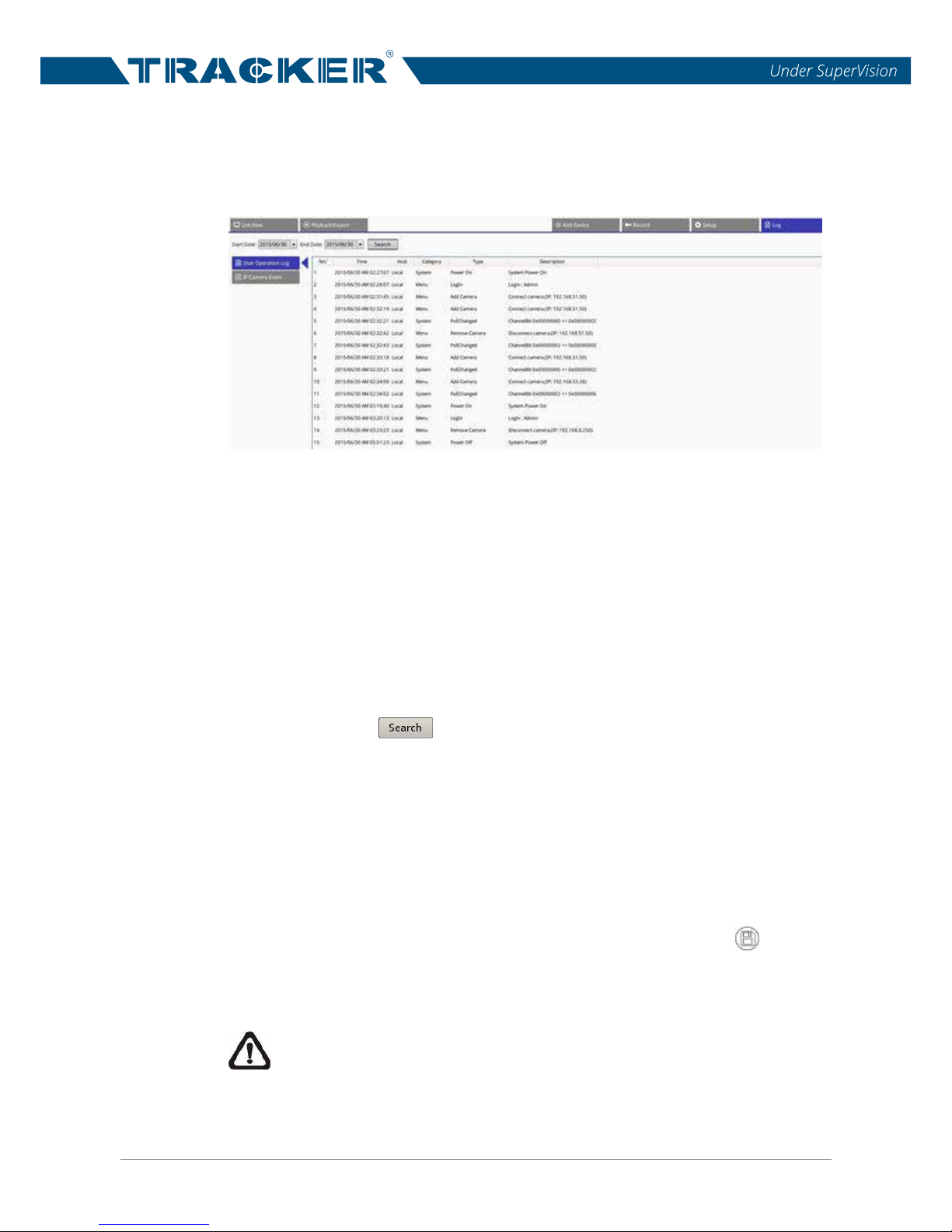
The NVR divides log data into two categories, User Operation Log and IP
Camera Event Log. Select the desired log category item on the left of the Log
tab to enter its corresponding log menu. Follow the steps below to search and
view the desired log data.
First, set the time range of the log data search by assigning the Start Dat
e
and End Date on the top-left of the function tab.
Then, click on < >, and the NVR will start searching and then list all
the recorded log data within the set time.
Click on each log category item on the left of the Log menu to view its
corresponding log data found within the set time.
8.2 Export Log Data
After searching the log data, users can export the desired data if necessary.
In the desired log type menu, click on the Backup Log icon < > at the
top-right corner of the Log tab, and an Export window will pop up. Click on
<Confirm> to start exporting the log data, or click on <Cancel> to abort.
NOTE: The NVR will export all log data in the selected log type menu.
The file format of the exported log data is *.txt.
 Loading...