

Page 1

Maxima Receiver
Page 2

Notes
Page 3

Congratulations! The Tracker Maxma Receiver System will provide you
with state of the art radio-location technology for hunting dogs, pets,
wildlife research, people tracking and law enforcement applications.
This User's Guide is intended to provide you with information on the
functions of the equipment as well as the basics of radio-location
techniques in order to get the most out of your system.
IMPORTANT:
READ ALL INSTRUCTIONS CAREFULLY before operating the receiver.
Warnings:
1. Never connect the unit to a power source (through external
power jack) without employing the Tracker External Power
Adapter (sold separately). Never connect the receiver to an AC
power source or reverse the polarization on a DC source.
2. Never operate the unit with a headset at high volume levels
3. Be careful to keep the receiver dry and minimize exposure to
rain, snow or other liquids.
4. Changes or modifications to this receiver, not approved by
Tracker Radio Systems, Inc. could void your authority to operate
this receiver under FCC regulations.
FCC ID: MWBFTV-466
T
his device complies with par
t 15 of the FCC rules. Operation is
subject to the following two conditions: 1) This device may not
cause harmful interference, and 2) this device must accept any
interference that may cause undesired operation.
Page 4

Table of Contents:
Features 1
Receiver upgrades 2
Integrated Antenna 2
Operating the receiver 3
Controls 4
LCD (Liquid Crystal Display) 5
Turning ON and OFF 5
Selecting memory locations 6
Automatic/Manual Modes 6
Plug-ins 7
Headphone jack 8
External Power jack 8
Automatic Shut-off 8
External antenna 8
Programming 9
Adding a frequency 9
Changing a frequency 10
Deleting a frequency 11
Changing the batteries 11
Maintenance 12
Using your system 13
Getting Started 13
Effective Range 18
Obstacles 19
Signal bounce 19
Polarization 19
Overhead Utilities 20
Use in and around a vehicle 20
Location of Transmitter 20
Location of Receiver 21
Triangulation 21
Use of a Vehicle 23
Accessories 24
Troubleshooting 25
Specifications 29
Page 5

Feature Summary:
• Fully synthesized receiver with programmable EEPROM memory
• Available in 4 Frequency ranges (150Mhz through 157Mhz,
164Mhz, 213Mhz through 223Mhz, and 433Mhz through 434Mhz).
• Fully programmable with up to 100 Memory locations
• Manual and Automatic gain control modes
• Large custom-designed Liquid Crystal Display (LCD)
• Microprocessor controlled functions, supervises synthesizer
• Backlit screen-with automatic light sensor to automatically activate
backlighting when required
• Low battery indicator
• Automatic shut-off
• External power jack (for use with optional 9 V adapter)
• Headphone jack
• Patented, virtually unbreakable antenna elements with 10 year
warranty incorporating steel hinges
• External antenna capable, either using bracket with external
antenna jack or upgrading receiver with external antenna jack (SMA)
•
Rugged body
, CNC milled from a solid aluminum bar and
powder coated
•
Splash proof design
1
Tracker Maxima Models:
Models
Number of Frequencies/channels
1 kHz steps
Memory locations
Duo 1000 2
1000/5 1000 5
2000/15 2000 15
5000/25 5000 25
Page 6
Receiver upgrades:
Any Maxima receiver is upgradeable to monitor additional frequencies and memory locations (up to 100) by sending the unit to
Tracker. Charges are assessed for upgrading and shipping.
MAXIMA RECEIVER
The Tracker MAXIMA is a Directional Receiver for numerous
applications. The receiver is programmable within a frequency
range that matches the integrated antenna. The receiver body is
precision CNC milled from a solid aluminum bar and powder
coated. The antennas fold alongside the body of the receiver to
create the most easily transportable receiver/antenna combination available anywhere in the world.
Below is a review of the important features of the Maxima receiver.
Integrated Antenna:
A key feature of the Tracker Maxima receiver is the integrated folding antenna. Tracker antennas feature steel hinges connecting the
antenna elements to the receiver. You will notice that the antennas
are made of virtually unbreakable circuit board material. The
patented design allows the mechanical leng
th of the antenna to be
significantly shorter than the required electrical length.
2
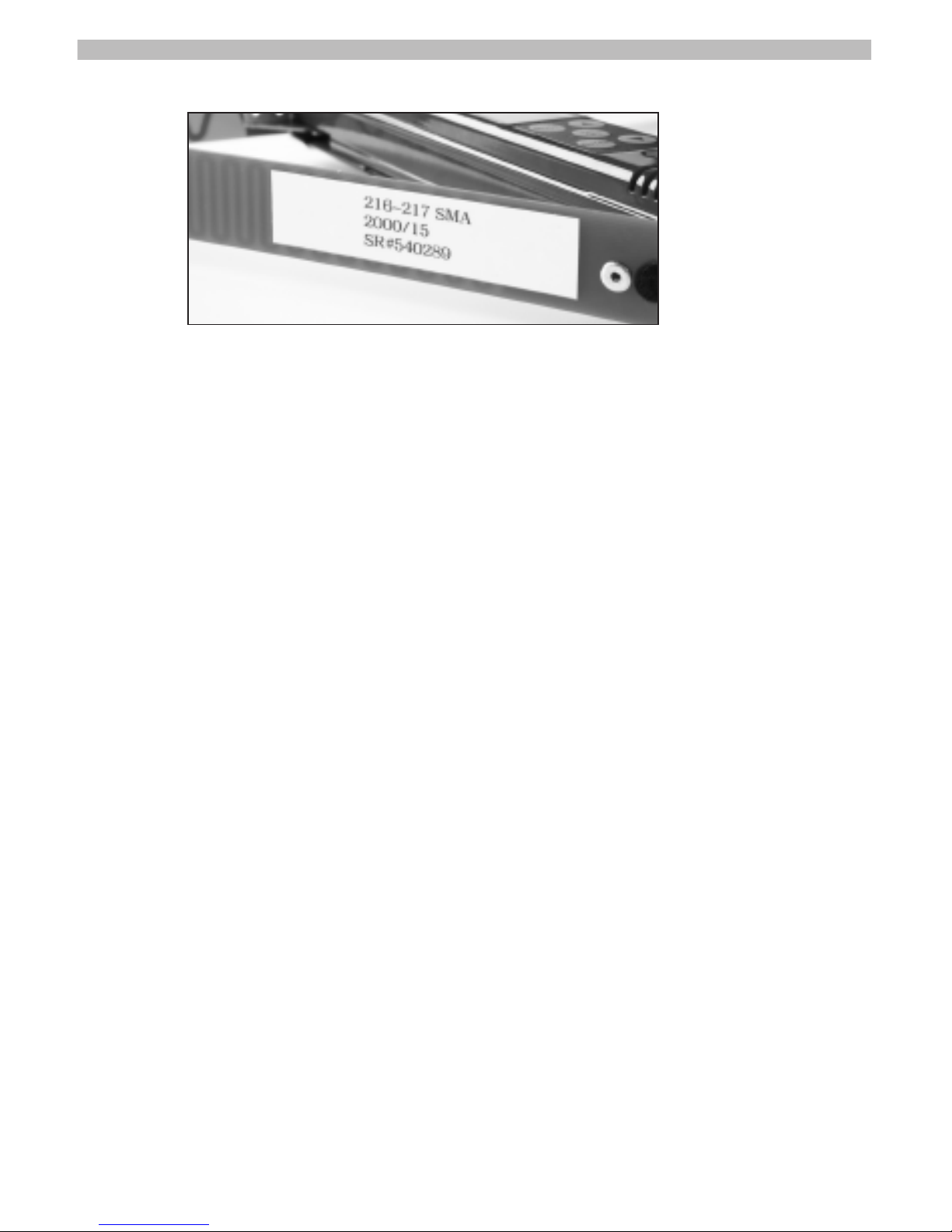
Base Frequency, model number and serial number are indicated on left rear antenna.
Page 7
Operating the receiver:
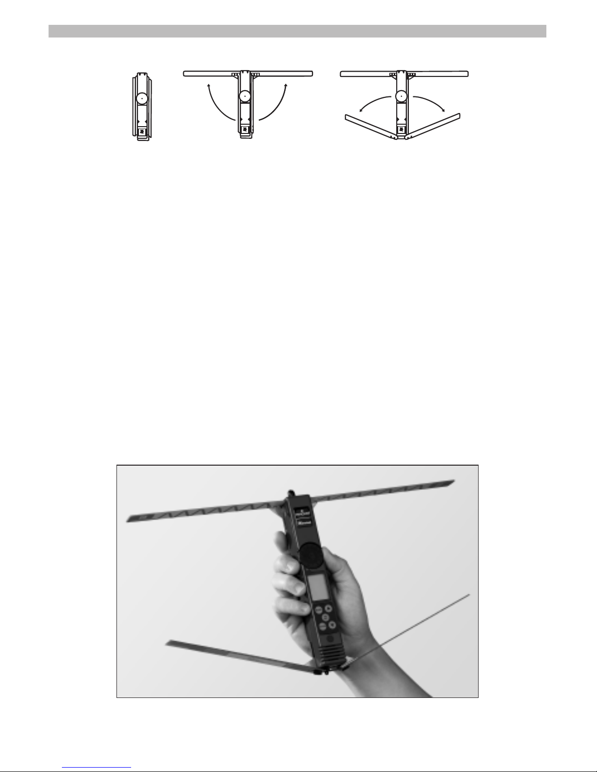
To utilize the receiver, first unfold the antennas before activating
the receiver. The receiving antennas are located to the front of
the receiver and when fully extended are perpendicular to the
axis of the receiver. The reflecting antennas are located to the
back and when fully extended form a 75 degree angle to the
axis of the receiver. All four elements need to be extended
when tracking.
Grasp the receiver in one hand with your thumb close to the
gain wheel. For best results, be careful not to touch the antenna
as you track. In particular, do not allow the rear antennas to rest
on your wrist or forearm, as this can affect the bearing accuracy.
3
Correct way to hold Receiver
Page 8
4
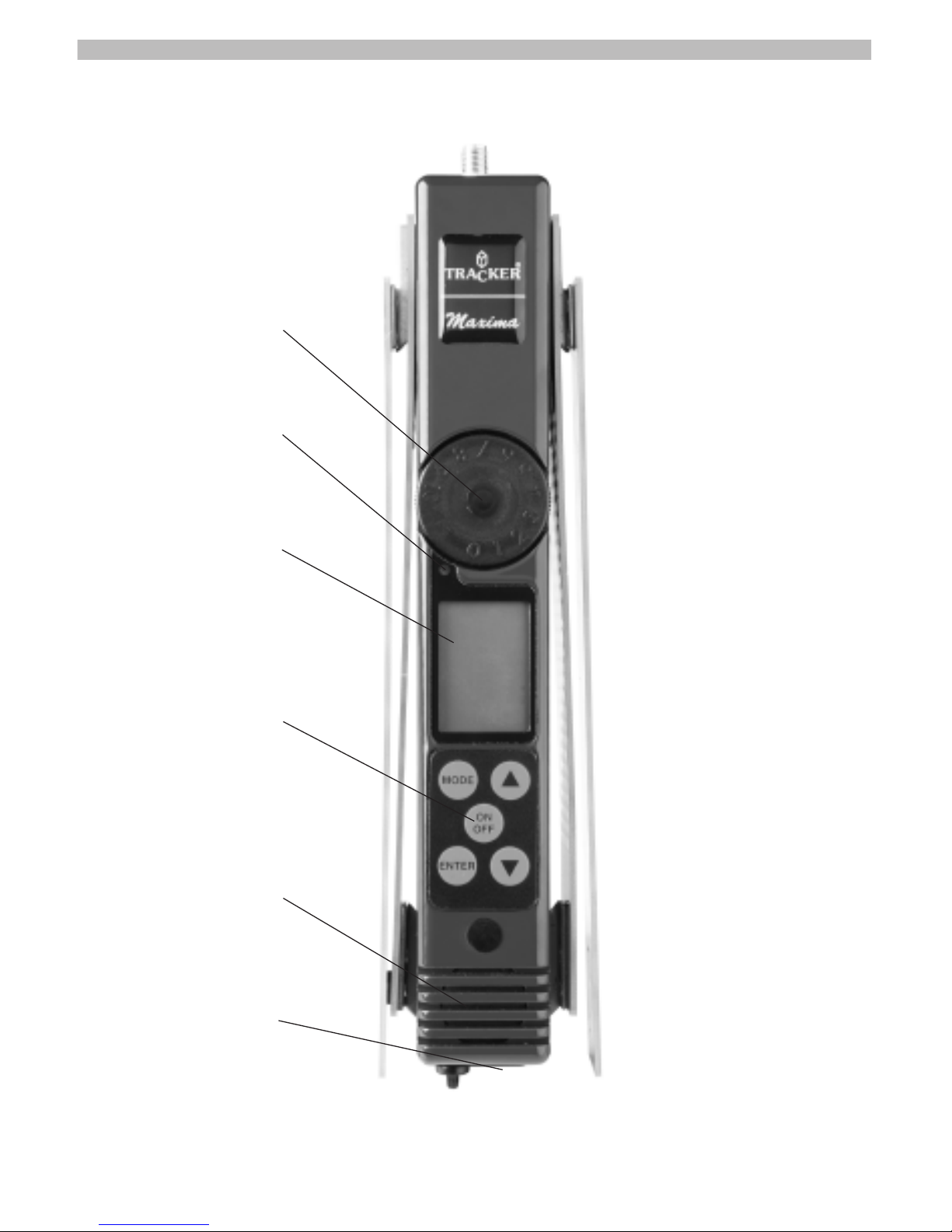
Gain Wheel
Light Sensor (for backlight)
LCD Screen
Operating Buttons
Speaker
Jacks
Controls:
front
back
Page 9
Operating the Maxima Receiver:
Turning the receiver ON:
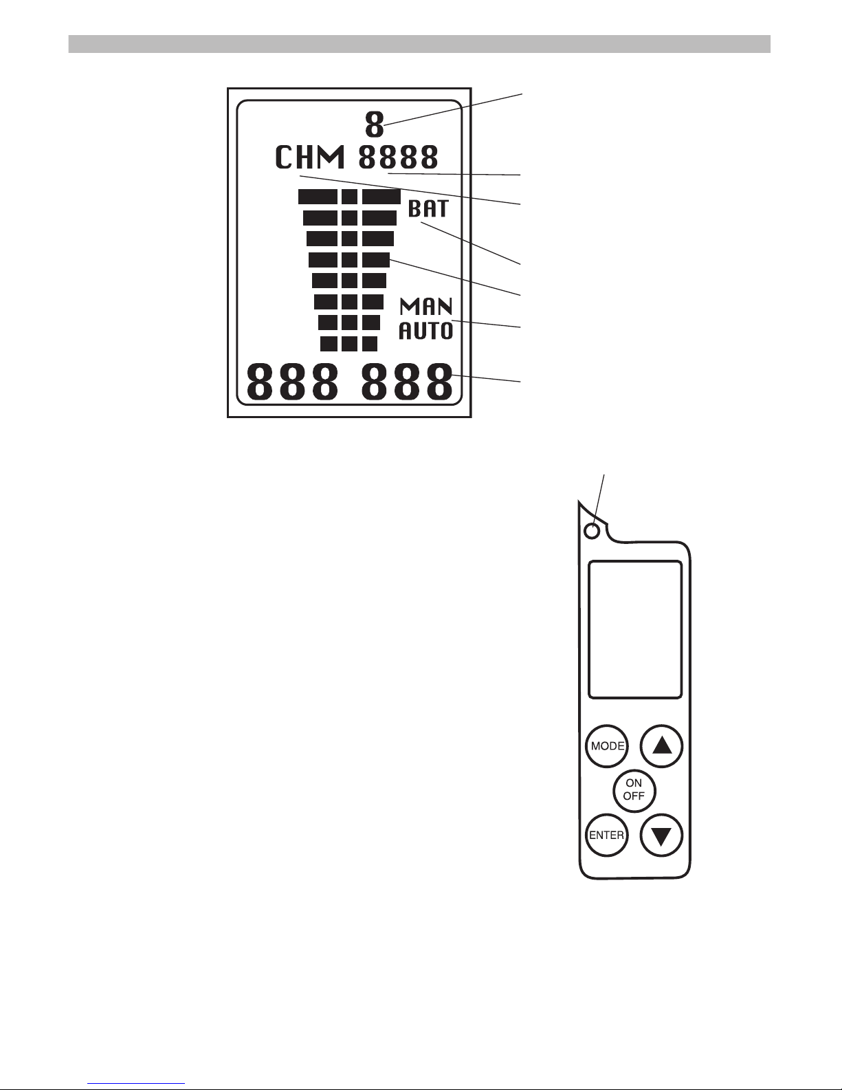
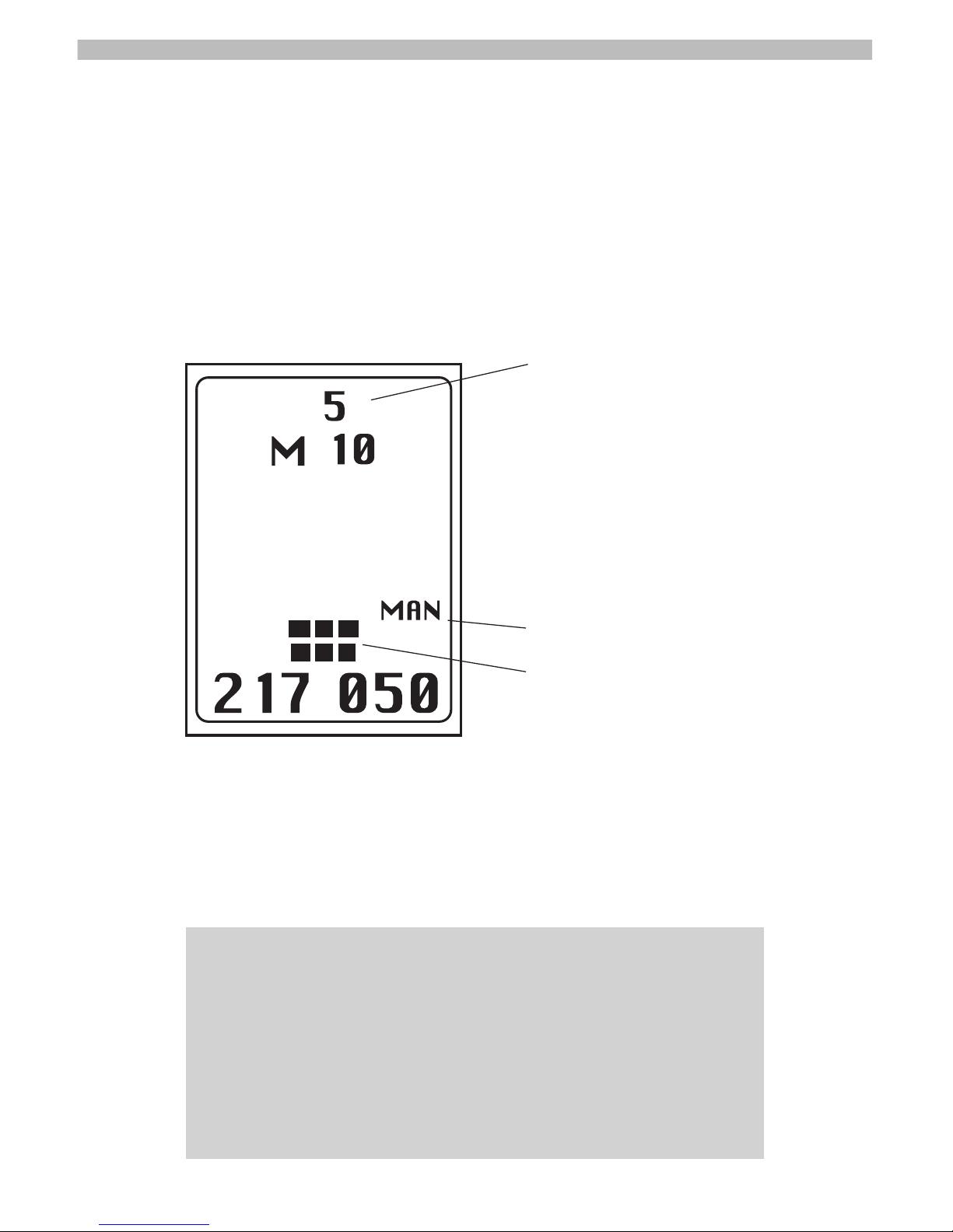
Press and hold the ON/OFF switch for approximately 1- 2 seconds. On power up the receiver will perform a Self Test. The Backlight on the
Liquid Crystal Display (LCD) will illuminate for
one second and the display will appear as in
above illustration. Following self-test the unit
will be ready for use. Current settings (frequency, gain mode, gain setting) will be displayed.
Turning the receiver OFF:
Press and hold the ON/OFF switch for approximately 1 - 2 seconds. When the LCD displays
no information the unit is off.
5
Gain Setting
Mode indication display, Memory/Channel
Channel editor and memory location
Low battery indicator
Signal strength bar graph
Manual/Automatic gain control mode
Current frequency
Light sensor to activate backlight.
Page 10
Selecting Memory location:
Use the s and t buttons to move between Memory locations
that have programmed frequencies saved. The programmed
frequencies are displayed at the bottom of the Display. During
programming, use the
s button to change to a higher number
and the
t button change to a lower number.
Automatic/Manual Gain modes:
The gain should be set carefully in order to detect the transmitter
and to help in direction finding. A gain setting that is too high
will make it difficult to determine a bearing to the transmitter.
6
IMPORTANT NOTE: When the receiver is turned on, it will always
return to the last Memory location and Modes as when it was shut
off, i.e. M1, (automatic or manual) and gain level (in Manual). For
example, if you were monitoring 217.050 MHz frequency in Manual
mode at gain setting 8 when you turned the unit off, it will return to
217.050, Manual mode and gain setting 8 when turned on again, if
the Gain control Knob was not moved. Automatic Mode will always
have the gain go to maximum then adjust.
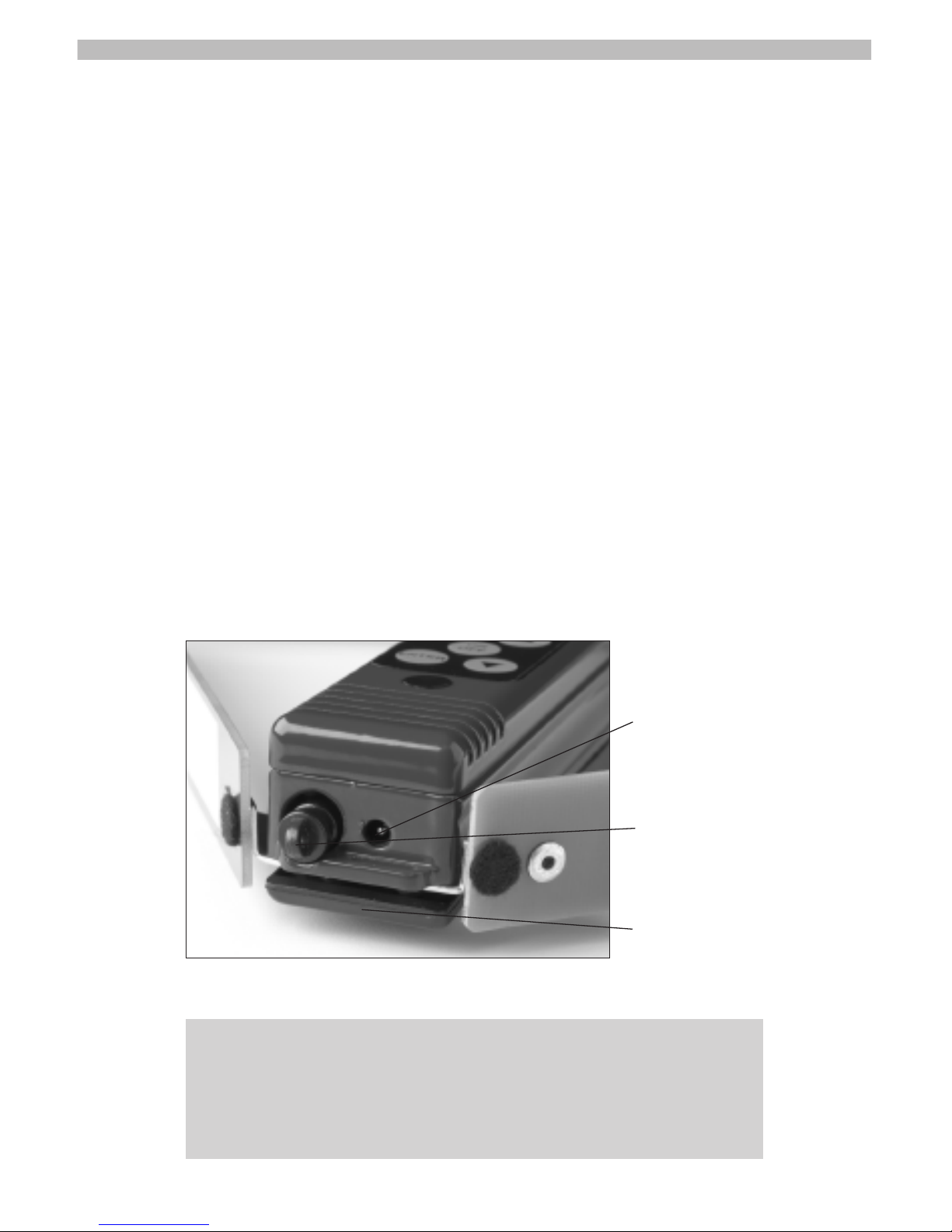
Gain Setting
Manual mode indicator
Optimum gain level for tracking
Page 11
A unique feature of the Maxima receiver is the automatic gain
control mode. The “smart electronics” contained in the receiver
will automatically set the gain control based on the strength of
the signal. Note that automatic is good to help find a signal;
Manual is best for precise direction finding.
Manual mode allows the operator to set the gain level. Turn the
gain wheel to the lowest level where an audible beep is heard
and one or two bars are displayed on the LCD (see photo on
pg. 6). This will provide the most precise indication of bearing to
the transmitter.
Pressing the ENTER key when in memory selection mode, toggles receiver between Automatic and Manual gain control
modes. MAN or AUTO will indicate the current mode and displayed on the right side of the LCD screen. When in Automatic
mode, the AUTO will flash when adjusting gain. Current gain setting is displayed top center (0 through 9).
Plug ins:
7
IMPORTANT NOTE: Do not attach a ring or other attachment to
plastic plug for purposes of a safety strap. This may cause the
plug to break off requiring factory service. Use metal flange adjacent to the DC power jack to attach receiver to holster, belt, etc.
Sound cut-off/Headphone jack
External Power jack
Attachment flange
Page 12
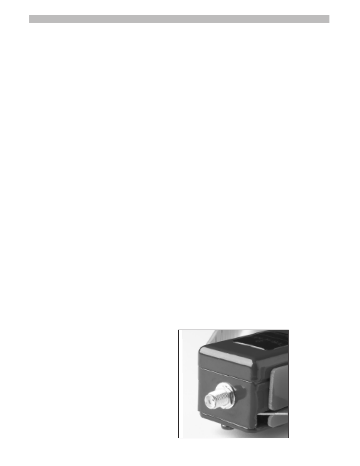
Sound cut-off/Headphone Jack:
There is a plastic Mute plug that has three positions:
In: Sound on
Out (
1
⁄8"): Sound off
Removed: For headphones (internal speaker off when
headphones/external speaker is used)
The Headphone Jack takes a standard mini (
1
⁄8") headphone plug
(headphones sold separately) Note that the speaker is OFF
when the headphones are plugged in. The signal is audible in
both headphone speakers. When removing the plug to allow the
use of headphones, pull straight out. A string fed through the
hole in the plug may help with removal.
External power Jack:
Used to power unit from a car's cigarette lighter (accessory sold
separately). Use only the 9 volt DC regulated adaptor available
from Tracker.
Automatic Shut-off:
The Tracker receiver features an automatic shut-off circuit that will
guard against running down the batteries if the receiver is inadvertently left on. Most receivers are set to shut down after 15
minutes if no button is pressed.
External Antenna/Connector:
Maxima receivers may be
purchased with an SMA connector for use with an external antenna (for example a
roof-mounted or hand-held
Yagi). Additionally, most units
can be retrofitted with this
adapter by sending the
receiver directly to T
racker
.
8
Page 13

External antennas are commonly employed when tracking from a
vehicle or aircraft. Moreover, a multi-element directional antenna
can provide greater range when tracking a very weak transmitter.
Most Tracker transmitters are powerful enough to not require an
external antenna except in specilized circumstances.
PROGRAMMING
Adding a frequency:
1. Turn ON the receiver.
2. Press MODE button, M changes to CH in mode indication dis-
play line and memory number is replaced by 4 numbers with
the first digit (left) blinking. Note that the current frequency is
displayed at the bottom of LCD. These four numbers will be
added to the base frequency (listed on antenna label) of your
receiver. For example: if you have a 216 MHz receiver, the
base frequency is 216.000. Some examples:
Example #1
The four digits read: CH 0155
The base frequency: 216.000
Added together equal: 216155 or 216.155
Example #2
The four digits read: CH 2450
The base frequency: 216.000
Added together equal: 218450 or 218.450
If the blinking digit requires changing, use
s or t button to
select correct number. Press ENTER to save the number and
move on to the next dig
it (right). Again use
s or t button
9
NOTE: Note that the actual frequency will show at the bottom of
your Display
. The decimal point is understood between the 3rd
and 4th dig
its.
Page 14

to select correct number. Note that pressing the ENTER key
moves the editor 1 digit to the RIGHT and pressing the
MODE key moves the editor 1 digit to the LEFT.
3. Repeat until frequency at bottom of display matches desired
frequency. Note: that if an active transmitter is within range, it
should be audible. You can adjust the frequency to optimize
the sound by using the
s or t button furthest to the right
before saving the frequency.
4. With the last digit blinking, press ENTER to save the frequency.
A suggested location number will blink. If the desired memory location is not displayed use the
s or t button to selected
the desired location number.
5. Press ENTER to save the frequency in the displayed memory
location register. This will end the programming mode and
return you to memory location mode
Changing a frequency:
The process of changing a frequency is similar to adding a
frequency. Most users store the new frequency in the old memory location.
1. Turn ON the receiver.
2. Press MODE button, M changes to CH in mode indication dis-
play line and memory number is replaced by 4 numbers with
the first dig
it (left) blinking. Note that the current frequency is
displayed at the bottom of LCD.
10
HINT! It is best to note the memory location you want to store
your frequencies in before initiating the programming mode. After
you key in the desired frequency, the receiver will designate the
lowest available (empty) memory location to store the frequency.
If you have keyed in the desired frequency but forgot the intended
location, press the ON/OFF button for
1
⁄2 second, this will put you
back into memory selection mode. Then identify the memory
location you want to store the frequency in and start over.
Page 15

3. If blinking digit requires changing, use s or t buttons to
select correct number. Note that pressing the ENTER key
move the editor 1 digit to the RIGHT and pressing the MODE
key moves the editor 1 digit to the LEFT.
4. Press ENTER to move and edit next digit (right). Note that it
is blinking. Use
s or t buttons to select correct number.
5. Repeat until frequency at bottom of display matches desired
frequency. Note: that if an active transmitter is within range, it
should be audible. You can adjust the frequency to optimize
the sound by using the
s or t button on the rightmost digit
before saving the frequency.
6. Press ENTER to save the frequency. The memory location
number will blink. If the desired memory location is not displayed use the
s or t button to selected the desired loca-
tion number.
7. Press ENTER to save the frequency in the displayed memory
location register.
Deleting a frequency:
1. Turn ON the receiver.
2. Use
s or t to select the frequency (memory location) you
want to delete.
3. Press MODE button, M changes to CH in mode indication display line and memory number is replaced by 4 numbers with
the first digit (left) blinking. Note that the current frequency is
displayed at the bottom of LCD.
4. With the first digit (left) blinking, press
t button until you see
four blinking dashes on the Mode indication display line.
5. Press ENTER, Note that the receiver automatically selects the
location that you started with in step one.
6.
Press ENTER again and the memory location is now empty
and you are returned to memory selection mode.
11
Page 16
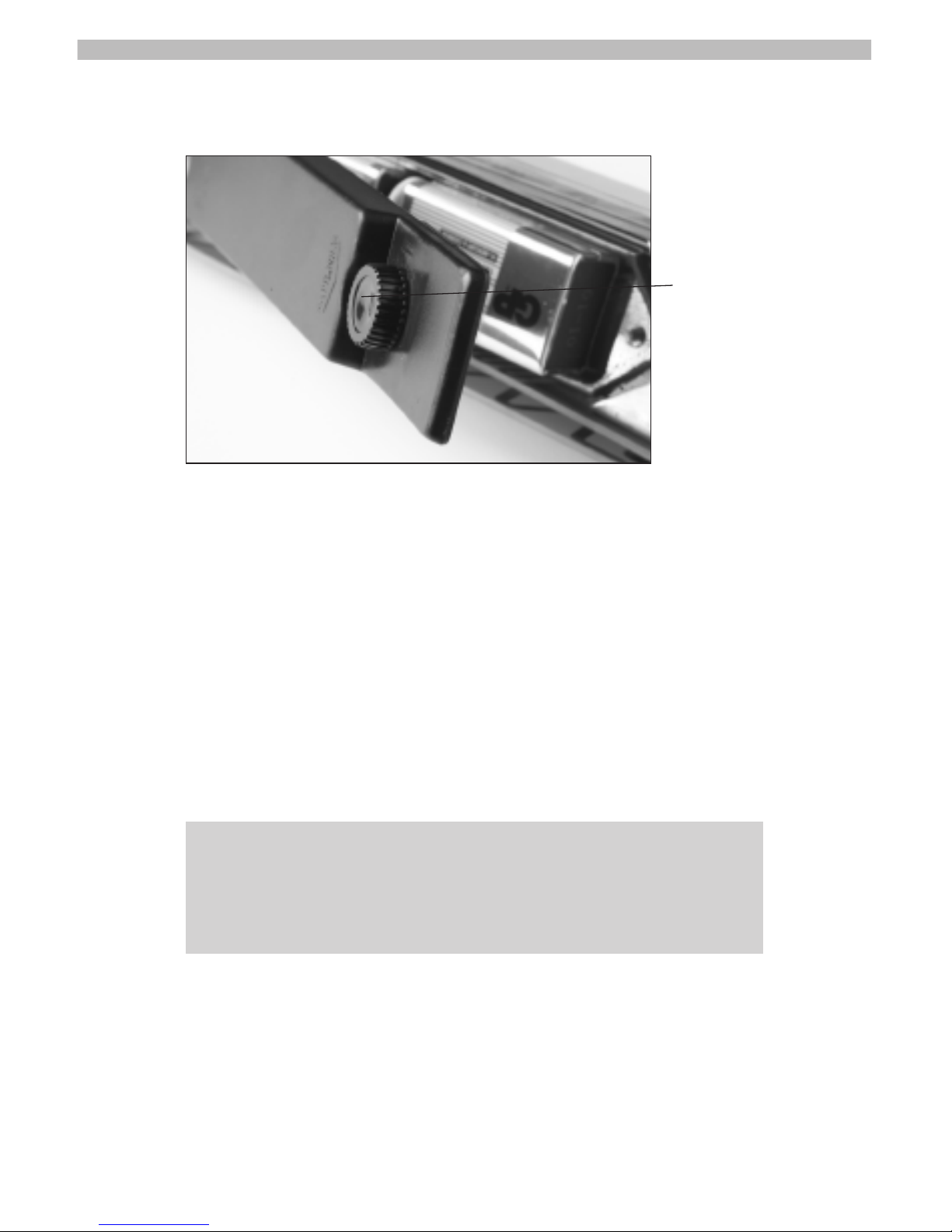
Changing the Batteries:
1. Start by turning the receiver upside down to allow access to
battery compartment.
2. Loosen the retaining screw on the battery cover and remove
the cover exposing the two 9 Volt batteries.
3. Replace BOTH batteries with 9 Volt batteries of same type and
equal strength. New 9 Volt Alkaline batteries are recommended.
4. Replace the battery compartment cover - start by inserting forward edge in slot at the front end of the compartment.
5. Tighten the retaining screw.
Maintenance
The MAXIMA receiver is designed to be relatively trouble free.
You can prolong the life of your system by following these simple suggestions:
1. Store the unit in a dry place at room temperature when not
in use.
12
Retaining screw
TIP: When removing batteries hold the battery clip in one hand
and remove first battery then reverse for second battery. This
protects possible loosening of battery wires. Do not allow batteries to dangle from battery wires.
Page 17

2. Minimize the contact with water. Tracker receivers are among
the most water resistant on the market but no unit is waterproof. Do not store receiver in a wet holster. If unit is submerged in water or becomes soaked, immediately remove
the batteries and ship unit to Tracker where it can be chemically cleaned and dried. WARNING: If a receiver is stored
wet and left to dry, pockets of water may be left under components. This will cause corrosion and damage, even though
unit may work.
3. When batteries are weak, replace BOTH at the same time. Both
batteries should be identical type (9V - non rechargeable, etc.).
Good quality alkaline batteries are recommended. Rechargeable
batteries may be used but, if employed, the low battery indicator
may not provide much, if any, warning.
4. If the receiver becomes soiled, the body and antenna can be
cleaned with alcohol or damp cloth.
5. If the antennas fold in and out with difficulty, DO NOT lubricate. Lubrication requires a special non-penetrating conductive
lubricant and is best accomplished by sending the unit to
Tracker for service.
6. Do not try to adjust the forward/front antennas as it may
cause damage to the circuit board, If forward/front antennas
are loose (will not stay in the open position), send unit in
for service.
USING YOUR SYSTEM
GETTING STARTED
It is important to acquaint yourself with the features of the receiver
before taking it in the field. While your system is simple yet powerful, you will need a little practice to become proficient in its use and
13
TIP: Your Maxima receiver will fit into a one gallon plastic zip lock
bag with the antennas open.
Page 18

be able to “read” the signal in different locations. It is highly recommended that you practice first before taking your dog hunting,
searching for a lost individual or tracking stolen property.
A tracking transmitter broadcasts a distinctive beeping sound in all
directions in a manner similar to an FM Broadcast station. The
Maxima receives the signal and provides an indication of the signal strength. The signal strength of the transmitter detected by the
receiver will depend on many factors such as distance to the transmitter, obstacles, signal bounce and antenna polarization. The
unique antenna of the Tracker Maxima is designed to favor
reception from one direction. When the Maxima is pointing in
the direction of the transmitter, the signal will be stronger.
The observed strength of the signal depends on the amplitude
of the wave detected by the receiver. The higher the signal
amplitude, the greater the signal indicated by the Tracker receiver. Radio waves spread in all directions from the source of the
transmission. As the spreading signals travel away from the
source their amplitude decreases and the indicated signal level is
reduced. The antenna's function is to receive the waves for the
receiver to process.
The degree of difficulty in locating a transmitter can vary considerably. Key factors include, landscape, natural and man-made
obstructions (trees, buildings, power lines, etc.) and weather conditions. These factors influence the strength of the signal
received either by attenuating (reducing the strength of the signal) or creating a reflection that will indicate a “false position”
where the signal will “bounce off” an object. Understanding how
the signal is influenced by these factors will vastly improve your
ability to locate a dog, wild animal, lost individual or proper
ty
.
14
HINT: Make sure you take the time to familiarize yourself with
the controls before tracking a transmitter in the field. With a little
practice you will become a proficient tracker.
Page 19

To become proficient with the operation of the receiver, you should
consider activating a transmitter, and have someone in your family
or group place it in an open area free from obstructions (where it
can be relocated, if necessary). A good distance to start would be
at least several hundred yards. Turn on the receiver, switch to the
correct frequency, set gain control to Manual, and reduce the gain
setting so that only 2 to 3 bars shows on the LCD screen in the
direction of the strongest signal. Once this is completed, keep the
receiver on and walk toward the strongest signal sweeping continuously in a 180 degree arc that contains the strongest signal. As you
approach the transmitter (indicated by the signal becoming
stronger) continue to reduce the gain (turn knob counter-clockwise)
so that only 2 to 3 bars are displayed in the direction of the
strongest signal. You should quickly locate the transmitter after a little practice. After you become proficient in locating the transmitter
in a flat area (line-of-sight), you are ready to practice in more challenging landscape.
The speed of the sweep is important. If you sweep too fast, it
will be difficult to get an accurate reading. A steady sweep is
best to start in order to get an initial reading. Once you have an
initial bearing indication, verify that your bearing is correct by
making a few sweeps in other directions. Practice will provide
you with the correct technique.
In the line-of-sight exercise, you should have noted several characteristics of the signal:
• The bearing of strongest signal was fairly consistent.
•
T
he signal streng
th diminished in a consistent pattern as you
varied 30 or more degrees right or left of the true bearing to
the transmitter
.
15
HINT: Pay particular attention to the gain control setting. It is
much easier to track a transmitter when the gain is set at the lowest setting that yields an audible signal. If you are using MANUAL
gain control mode, adjust the gain downward until the signal is
barely audible (2 to 3 bars on the LCD screen).
Page 20
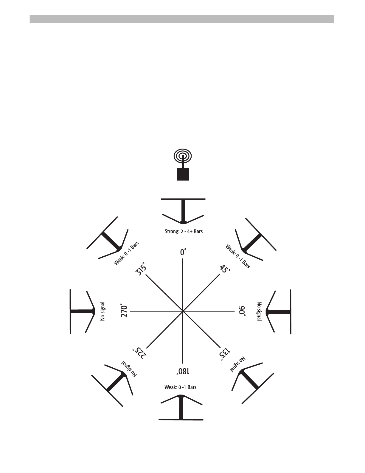
It is important to remember the characteristics of a line-of-sight
situation as it will aid in "reading" the signal in the field.
Next repeat the practice procedure in an area similar to your
search area (open fields, forested area, etc.). By this point, you
should have mastered the few controls that are required on the
Tracker receiver. This is important as your attention should be
focused on analyzing the signal rather than operating the receiver. If the frequency is set correctly, the gain mode is in MAN and
the gain level is set correctly, your attention can then be focused
16
Figure 1: Typical receiver behavior in line-of-sight situations
Transmitting Collar
Page 21

on interpreting the signal. As you proceed with more complicated searches, it is important to keep moving as you are processing new data at each new location rather than re-sampling the
same data when stationary.
Follow a similar procedure as in the previous example. Have
someone from your family or unit hide the transmitter in an area
that will provide a range of obstructions (physical and/or manmade) and special situations (inside a building, adjacent to metal
equipment, etc,) to the location team. Unfold the antennas, activate the receiver, select the correct channel and determine if a
signal is present. If the signal is heard, slowly sweep 360
degrees to ascertain the direction of strongest signal. You may
notice that you receive a relatively similar strength signal from
two or more directions. Under these circumstances, first try to
ascertain whether a metal building, hillside or other obstruction
is the source of the "bounce" signal. While there is no universal
method for analyzing multiple strong signals, try the following
when encountering a "bounce signal candidate:"
• Move to another location some distance away and repeat the
procedure. Try to remember the bearing that you received
strong signals at the first location and note if a new signal
comes from a common point.
• If you can easily reach a higher elevation (increasing the odds
for a line-of-sight signal), take another reading.
• If the object at the source of the bounce is small, try moving
perpendicular to a line between you and the source of the
signal. Often if the angle is changed the strength of the signal
will change significantly. If this occurs, review the initial angle
to create a possible candidate bearing to the transmitter or
eliminate this bearing (bounce signal).
17
NO
TE:
As you search with the receiver on, you may note that after
15 minutes of continuous use where no key is pressed, the receiver
automatically turns off (you may need to turn the receiver on again).
Page 22

• Implement a "process of elimination" strategy. If the signal is
difficult to "read" remove from consideration all line-of-sight
locations that you do not receive a strong signal.
You will notice that the signal in the open field led you directly to
the transmitter while in hilly area the direction changes slightly as
you move around obstacles and hills. This signal “bounce” is
completely normal and eventually, with practice, you will be able
to “read” the signal in relation to the terrain.
A signal is not required to be line-of-sight to yield a good bearing. In gentle rolling topography with few obstructions, radio
waves can follow the contour of the ground and provide a good
bearing. However, distance estimation is complicated as the signal is attenuated (strength reduced) while following ground contours. Often the bearing will change slightly as you approach
the transmitter across rolling landscape.
EFFECTIVE RANGE
Transmitter and receiver location will affect the range we can
detect the signal from the transmitter. On flat open country with
few obstructions (trees, large rocks, homes, etc.) we will get
maximum range out of our system. In steep hilly terrain or in a
large city, the range can be reduced significantly.
Distance can be estimated after you have gained experience tracking in the same terrain using the same transmitter. You may note
that a signal received at a gain level of 6 is much farther away than
one received on a gain level of 5 in the same terrain. The gain
18
H
I
NT!
It is generally helpful to know the relative distance and
bearing of the transmitter. To become proficient at judging distance, note the gain setting either on the top of the L
CD display
or on the wheel. Remember that gain is a logarithmic scale so a
setting of 8 or 9 may indicate that the transmitter is 8 to 1
0 miles
away OR the signal is obstructed by topography or buildings.
W
ith practice, you will quickly be able to accurately judge distance
under most circumstances.
Page 23

scale is logarithmic not linear. This means the change in gain from 1
to 2 is very small as compared to the change in gain from 5 to 6, i.e.
gain at 1 to 2 is for 50 to 100 ft. while gain at 5 to 6 is for
1
⁄2 mile to 2 miles. This is not an exact measure, the ranges will be dif-
ferent depending on all of the factors involved. NOTE - If the signal is
not line-of-sight, distance estimation is not reliable.
Obstacles
Think about what happens to the signal strength of your favorite
radio signal when your vehicle enters a tunnel? It gets very faint or
you lose it altogether. The same effect can be experienced when
searching for a cell phone signal in a deep canyon. Radio waves at
certain frequencies have great difficulty penetrating rock and other
solid objects. Therefore, it is generally more challenging to locate an
object in rugged terrain rather that on a flat plain.
Signal Bounce
The term that professionals use to describe the behavior of radio waves
deflecting and reflecting off objects is “signal bounce.” Many different
types of substances reflect radio waves including rock (particularly shear
cliffs), water and wet vegetation. “Bounce” has a tendency to complicate radio-location as the signal will be effected by the composition and
shape of the reflecting object. This phenomenon has the potential to
create strong signals in several discrete directions. Signal bounce
should not be intimidating - we just need to learn how to manage it.
Polarization
The signal will be strongest when the orientation of the receiver
antenna matches the orientation of the transmitting antenna. For
19
Figure 2: Transmitter/receiver polarization
Page 24

example, if the transmitting antenna is perpendicular to the
ground, the signal strength detected by the receiver will be greatest when the antennas are positioned vertically. You can test
this for yourself by activating a transmitter and orienting the
antenna on the transmitter parallel to the ground. Then turn on
the receiver and test the signal strength with the antennas parallel and perpendicular to the antenna on the transmitter.
Knowing the orientation of the antenna in advance greatly aids in
radio location. However, it is often unknown and the best procedure is to try both vertical and horizontal antenna orientations
when tracking.
Overhead Utilities
Power lines are excellent re-radiators of radio waves and can
complicate radio-location. Like signal bounce, it is all very manageable once you understand the limitations of tracking near
power lines especially high voltage transmission lines.
Use in and around a vehicle
The receiver can be operated from a motor vehicle, however,
many older vehicles produce considerable interference and
make signal reception difficult (particularly a weak signal) when
the engine is running. When using the receiver without an external antenna it is best to shut off the vehicle and move at least
20 feet away. Be cautious of reflected signals off the vehicle. It
might be necessary to take readings from different points from
around the vehicle to get a good bearing.
Location of transmitter
There is a reason why TV and radio transmitters are located on
hilltops and towers - it provides maximum range for the signal.
Conversely, the closer to the ground the transmitter is situated,
the shorter the effective receiving range. Locating an object that
has fallen into a well or is flat on the ground is more difficult
g
iven the reduced effective range of the signal.
20
Page 25

Location of receiver
Similar to the location of the transmitter, any given signal can be
received at greater distance if the receiving antenna is high in the
air, therefore, a stronger signal may be obtained by positioning
the receiver higher off the ground. NOTE: It is much worse for
the receiver to be in a low terrain than the transmitter.
Triangulation
Consider the process of triangulation before embarking on a
cross-country search if any of the following conditions apply:
• If the transmitter is stationery
• Transmitter is located in difficult terrain
• Transmitter is at a great distance from the receiver.
This practice may be of limited utility for a fast moving transmitter (hunting dog, vehicle, etc.) as the procedure may take some
time and the transmitter may have moved a great distance.
It is best to triangulate the transmitter from several locations (3
to 5 are best). Ideally, the locations should be widely dispersed
to allow plotting on a map. Use of a GPS receiver to pinpoint
locations and a compass to determine bearing of strongest signal
will improve the accuracy of the triangulation. In addition, a set
of headphones will allow the operator to detect minute changes
in the signal to assist narrowing the band of maximum signal
strength. With the correct equipment and technique the operator should be able to narrow the search to a small area.
Suggested procedure is as follows:
1. Select 3 to 5 “listening” points that are widely dispersed (ide-
ally separated 30 to 120 degrees from each other).
Locations at higher altitude or where obstructions are at a
minimum are preferred.
2. Travel to each listening point, unfold the antenna, turn on the
receiver and carefully adjust the gain so a strong signal can
only be detected in a narrow arc (for example 30 to 60
21
Page 26
degrees). Note that, other things being equal, the arc may be
greater the closer you are to the transmitter. Listen for small
changes in the signal strength (headphones can be very helpful to detect the bearing of maximum signal strength). If you
know the orientation of the transmitter antenna, rotate the
receiver antenna in the same axis. If you are not sure of the
transmitter antenna orientation, experiment with various
antenna orientations (parallel to ground, perpendicular to
ground, 45 degrees from perpendicular, etc.) to determine
which provides the more precise bearing.
22
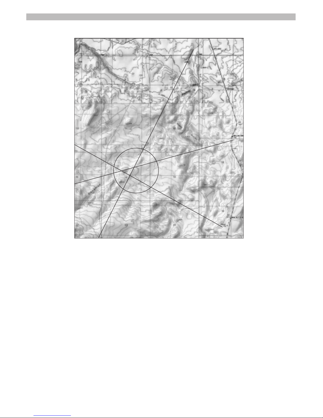
Figure 3: Plotting triangulation bearings on a topo map. The circle defines the
most likely location of transmitter
Page 27

23
3. If the arc of received signal is, say 30 degrees, note the bear-
ing of the “break” in signal (where the signal drops off) on
each side and choose the mid-point of the arc as the most
likely bearing to the transmitter.
4. With a compass record the bearing, then using the GPS
coordinates of the listening location, draw a line representing the bearing on a map. Add lines 10˚ on either side of
the initial line.
5. Repeat this procedure at 2 to 4 additional locations, plotting the
bearings that comprise the intersection of the lines on the map.
6. Determine the best path and commence the ground search.
The size of the search area may vary depending on terrain, radio
interference and other factors that impedes precise bearing.
Under most circumstances, an experienced user should be able
to define a bearing that is within 10 degrees of true. This will
result in a very small search area to undertake a thorough
ground search
Use from a Vehicle
The optional SMA connector (or bracket for older receivers),
omni directional antenna and 9 volt power adapter (for power
points or car cigarette lighters) can be employed to search for a
signal from a moving vehicle (assuming that interference is not
too great). This can be a time efficient approach if the exact location of a transmitter is not known and a road network is available. Drive until a signal is heard and then remove the receiver
from the bracket, unfold the antennas and take a bearing. Be
careful to move away from the vehicle to minimize signal reflection. Once a signal is received, you can elect to triangulate on
the signal or follow the road network toward the source of the
signal, repeat as necessary or desired. The omni-directional
antenna will not provide signal direction data but a strengthening
signal will indicate that the vehicle is approaching the transmitter.
Page 28
24
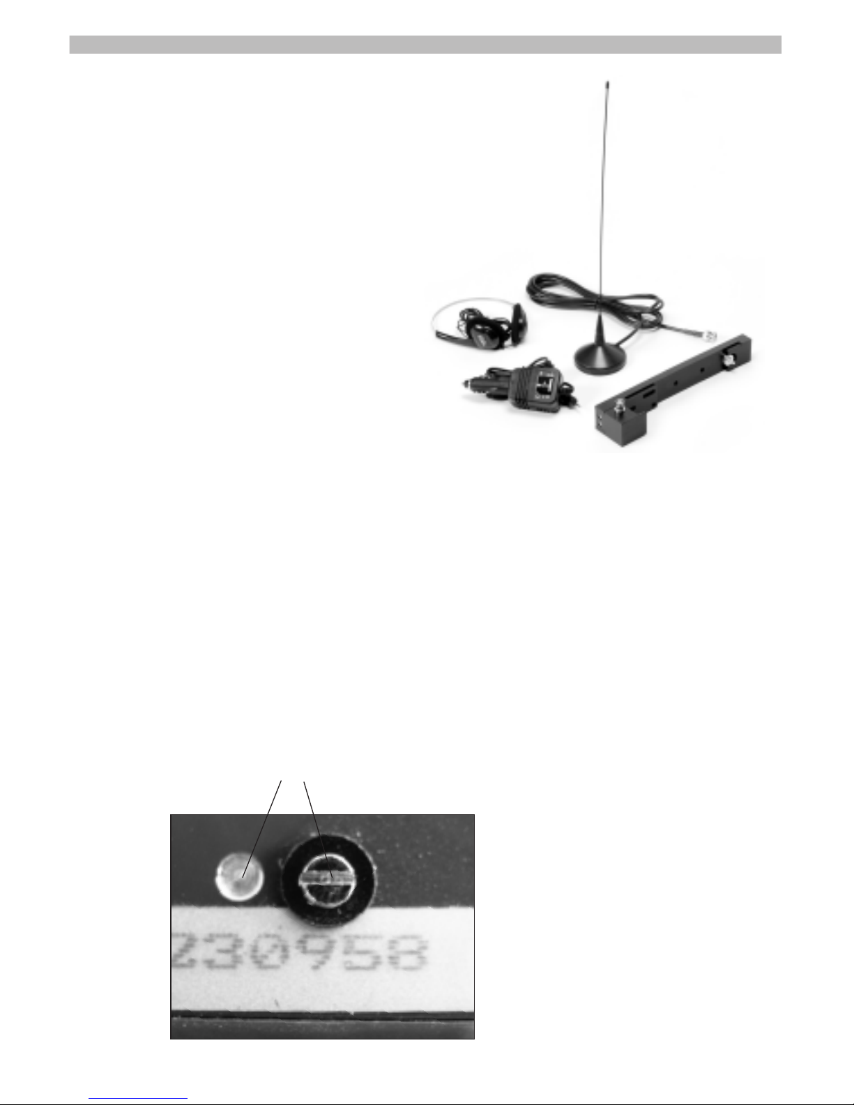
ACCESSORIES (Sold Separately):
In some cases the use of accessories can facilitate
the location of a transmitter particularly from a
vehicle. Tracker markets accessories including
an omni-directional antenna, mounting
bracket, headphones and DC power
adapter. The omni-directional
antenna features a magnetic
base, which attaches to the
roof of the vehicle and a coax
cable with BNC connector that
connects to the mounting
bracket, or adaptor for direct
connection to the receiver.
The mounting bracket holds the receiver and provides a BNC
connector for an external antenna. One can easily remove the
receiver from the bracket for use with its folding directional
antennas. Make sure your Maxima is enabled for an external by
checking the forward end of the receiver.
Headphones help monitor the strength of the signal particularly
when precision is required or signal is very weak.
The DC power adapter permits the user to power the receiver
from the vehicle's power point or cigarette lighter.
External antenna enabled for use with mounting bracket
Page 29

TRANSMITTERS:
For many applications, Tracker markets transmitters with the
Maxima receivers, as a package. See the manual for your transmitter type or download off of www.trackerradio.com
TROUBLESHOOTING:
Receiver will not turn on
1. Make sure you are pressing and holding the ON/OFF button
for at least 2 seconds.
2. Remove battery cover and check to make sure batteries are
connected and battery clip wires are ok. If wires are broken or
frayed, send unit in for service.
3. Use a battery tester, not a multimeter/volt meter to assure
that both batteries have sufficient strength.
4. Try replacing batteries. If unit still does not turn on, send unit
in for service.
Receiver is on but no sound is heard from speaker
1. Make sure gain control is set high enough to be able to acti-
vate speaker.
2. Insure the black plastic mute/silencer plug is all the way in
the headphone jack.
3. Try removing the plug.
4. If there is still no sound from the internal speaker, send unit
in for service.
Distorted Audio or loss of Signal
1. Check backlight operation by turning unit on (backlight should
come on for one second). If backlight does not illuminate,
send unit in for repair
.
25
Page 30

2. If audio distorts when backlight comes on, send unit in for repair.
3. If audio is distorted all the time, send unit in for repair.
Antenna/s loose or too tight
1. DO NOT try to tighten or adjust the front antennas, this can
damage the circuit board and will void your warranty.
2. Rear antennas can be adjusted with a screwdriver (screws are
located under battery retaining cover.) Antennas should be
snug but move smoothly in and out. Note: these are steel
screws in an aluminum body, so please be careful not to strip
the threads. If antennas cannot be adjusted for smooth operation, send unit in for repair. DO NOT oil or try to lubricate
the antennas, this can possibly damage the internal electronics and void your warranty.
Direction Accuracy
1. Insure antennas are fully extended.
2. Insure the back/reflecting antennas are not resting on forearm
or any part of you body.
3. If rear antennas are loose, adjust with a screwdriver for
smooth but snug operation (see above for explanation).
4. Check for corrosion on antenna rotating points/hinges. If
present, send unit in for service.
5. If none of the above causes are apparent and the problem
persists send unit in for service.
Reduced reception
1. If low battery indicator is on, change batteries in receiver.
2. Replace battery/s in transmitter (collar).
26
NO
TE:
DO NO
T put any metal or metallic tape or stickers on
the antennas.
Page 31

3. If available, compare receiver with another receiver with same
transmitter. If range is considerably less, send unit in for service.
Display screen flashes on and off
1. This is a programmed response; the number of flashes indi-
cates the type of problem the receiver self check system has
discovered. Send unit in for service.
Gain control numbers jump in value or change
1. Put unit in manual mode.
2. If problem is still present the gain control potentiometer is
defective or the gain program levels are corrupted and
required unit to be sent in for service.
Other problems: NOTE: All problems listed below
require the unit sent in for service.
1. Missing segment on display or broken display
2. Broken antenna element
3. Buttons that do not operate
4. Broken battery clip
5. Squeal from speaker that sounds like a bomb dropping- need
to note frequency this happens on, and send in for service.
6. If the unit is submerged or soaked, remove batteries immedi-
ately, and send receiver in for service.
Warning! If you allow a wet receiver to dry, the unit may initially
function normally, but there will be areas that will continue to
corrode and the unit will eventually fail and require service.
W
hen the receiver eventually fails the electronic circuit boards
may be so badly damaged they will require replacement, costing
$3
00.00 to $500.00 or more, and warranty will be voided.
Therefore, it is strongly recommended that you send the receiver
in for service if you think the unit may have gotten wet inside.
27
Page 32

How to send in a unit for repair:
Package receiver in holster and original box if possible, or box with
good padding, and include a note with the following information:
• Name and Address and phone/e-mail address of sender
• Copy of warranty paperwork or receipt
• Brief description of problem.
• Include your e-mail address for notifications of the following:
We have received your shipment
Estimates of repairs over $150, and
Return shipment of your items
The technicians would appreciate as much information as
you can provide in order to reduce repair time so that they
can ship your unit back as quickly as possible. The description “it doesn’t work” is not particularly helpful.
We recommend that you insure the unit
Send to:
Tracker Radio Systems
800 S. Industry Way
Suite 160
Meridian, ID 83642
28
Page 33

MAXIMA RECEIVER SPECIFICATIONS:
Weight with Batteries 13.5 oz (420g)
Dimensions (antenna folded) 81⁄4" x 2" x 11⁄2"
(210 x 48 x 35 mm)
Dimensions (antenna unfolded) 8
1
⁄4" x 16" x 11⁄2"
(210 x 405 x 35 mm)
Spurious emission < 2 nW
Intercept point -20dBm > 2 dB
Operating voltage 7 - 10 V DC
Battery types (2 pcs) 9V/6LR61 - 6AM6EU
Current consumptions 50 - 100 mA
Sensitivity -130 dB /.078ºV
Modulation A1
DAAA (digital automatic amplification adjustment) >130 dB
Audio frequency power max. 70 mW
Operating temperature -14 to 122° F
(-10 to + 45° C)
Storage temperature -27 to +131° F
(-30 to + 55° C)
Frequency Bands: 150.000-157.000 MHz
213.000-223.000 MHz
433.000-434.999 MHz
29
Page 34

30
Notes
Page 35

Tracker Radio Location Systems
800 South Industry Way
Suite 160
Meridian, Idaho 83642
(208) 514-4719
(800) 900-2113
www.trackerradio.com
 Loading...