

Page 1
STEP
1
STEP
2
STEP
3
STEP
4
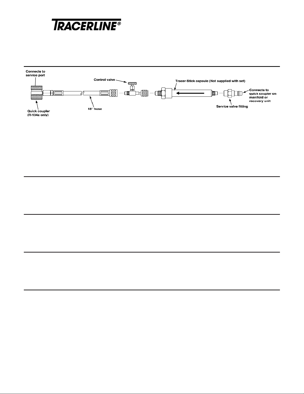
Connecting to the A/C system
For low-side charging, use the TP-3837:
Connect the quick coupler to the low-side service port of the system. Connect the service valve fitting to the low-side
quick coupler on the manifold or recovery unit.
For high-side charging, use the TP-9837:
Connect the quick coupler to the high-side service port of the system. Connect the service valve fitting to the high-side
quick coupler on the manifold or recovery unit.
Connecting the Tracer-Stick capsule to the service valve fitting
Turn the capsule over so the embossed arrow is pointing down. Remove the second cap and connect the service
valve fitting (supplied). Finger-tighten only.
Connecting the Tracer-Stick capsule to the control valve
Hold the Tracer-Stick capsule so that the embossed arrow is pointing up. Remove the black cap and attach the
capsule to the control valve (see diagram). Finger-tighten only.
Evacuating the connect set
Evacuate or purge the Universal Connect Set hose assembly. Close all valves finger-tight. Do not force. This will
damage the valve seat.
Universal Connect Set
™
Your choice for R-134a low-side or high-side charging
with PAG and Ester Tracer-Stick
®
Capsules
TP-3837 for Low-Side Charging • TP-9837 for High-Side Charging
Tracer-Stick®capsules are prefilled with Fluoro-Lite®UV-fluorescent dye. Tracerline®Universal Connect Sets™ make R-134a
A/C leak detection faster, easier and cleaner. They attach to 3/8-inch, 10mm and 1/2-inch hose fittings. The 18-inch hose
remains purged after the first use.
Use with Tracer-Stick capsules TP-3865, TP-3866, TP-3867 (for PAG) and TP-3875, TP-3876, TP-3877 (for ester).
For low-side charging, use TP-3837. For high-side charging, use TP-9837.
For detailed instructions about using the Tracer-Stick capsules, see the instruction sheet packed with them.
Page 2
STEP
5
STEP
6
STEP
7
STEP
8
Future dye injections
After completing the first dye injection according to these instructions, the hoses will be “prepurged” and will retain a
holding charge for future injections. This will eliminate the need for Step 1. The supplied dye-charging hose becomes a
dedicated line. If the control valve has been stored open, Step 1 must be repeated.
This Injection Device Certified to Meet SAE J2299 for R-134a and PAG and ester lubricants.
CAUTION
Protective safety glasses or goggles should always be worn while working on an air conditioning or refrigeration system or any
apparatus designed for use with pressurized fluids. UV-absorbing protective eyewear, such as TP-9940, is recommended for
protection from impact and maximum protection from ultraviolet radiation.
Cleaning and reinspecting after repairs
After all repairs are completed, it is important to clean off all fluorescent dye residue, otherwise the remaining dye
could be mistaken for a leak indication. To clean, use Tracer Products’ water-based GLO-AWAY™ dye
cleaner/remover or a general-purpose shop cleaner. Follow the directions for the cleaner used. After cleaning, check
all areas again with the UV lamp to make sure that no dye residue remains. Run the system a second time and reinspect with the UV lamp. If there is no glow, all the leaks have been found and repaired.
Inspecting for leaks
Run the A/C system for 5-10 minutes to allow the Fluoro-Lite dye to circulate. Inspect the system with a Tracerline
®
ultraviolet lamp. Leaks will glow a bright green color. Large leaks will be seen immediately. To discover smaller leaks,
schedule a return visit 24-48 hours later, after the customer has operated the A/C system as much as possible.
Disconnecting the Tracer-Stick capsule
Remove the service valve fitting from the Tracer-Stick and save it for future use. Disconnect the empty Tracer-Stick
and discard it.
Introducing the fluorescent dye/removing the connect set
For low-side charging:
With the A/C system operating, open the control valve and the quick couplers to allow refrigerant to flow through the
Tracer-Stick and into the system. Liquid refrigerant works best. After the Tracer-Stick clears, close the valve nearest the
refrigerant source first and allow the connecting hoses to reach the low-side pressure. Close the control valve and the
quick coupler on the TP-3837 and disconnect the set from the service port and the manifold or recovery unit.
For high-side charging:
Following the recommended procedure of the refrigerant charging apparatus, open the control valve and the quick
couplers to allow refrigerant to flow through the Tracer-Stick and into the system. After the Tracer-Stick clears, close
the control valve and the quick coupler on the TP-9837 and disconnect the set from the service port and the recovery unit.
12/96 A95248-2
PRINTED IN U.S.A.
 Loading...