

TRACE-LITE TLED110/EX Installation Instructions Manual

TLED110/EX
INSTALLATION INSTRUCTIONS
SAVE THESE INSTRUCTIONS!
READ CAREFULLY AND FOLLOW ALL INSTRUCTIONS FOR YOUR OWN SAFETY
• DISCONNECT AC POWER SUPPLY BEFORE SERVICING.
• Installation and servicing of this equipment should be performed by qualified service personnel only.
• Ensure the electricity connections conform to the National Electrical Code and local regulations if applicable.
• Do not mount near gas or electrical heaters.
• Equipment should be mounted in locations and at heights where it will not readily be subjected to tampering by
unauthorized personnel.
• The use of accessory equipment not recommended by the manufacturer may cause an unsafe condition. Any
modification or use of non-original components will void the warranty and product liability.
• Do not use this equipment for other than intended use.
INSTALLATION INSTRUCTIONS
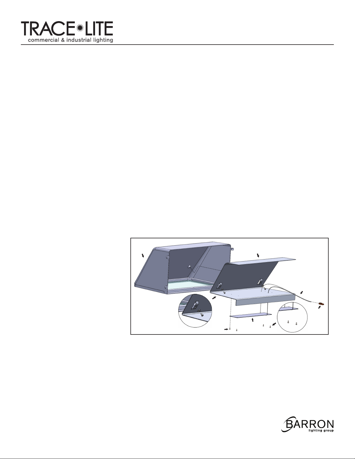
1. Unhinge refractor by loosening (2) screws.
2. Position the fixture over the junction box and mark the appropriate holes to be drilled to align the housing correctly
over the junction box then secure with hardware provided with junction box.
3. Pull wires through center hole of mounting plate and rear housing.
4. Use additional screws/bolts/fasteners along the housing to secure to the wall.
DO NOT RELY SOLELY ON FASTENERS AT THE JUNCTION BOX.
5. Electrical connections should be made inside junction box. Cap all unused leads to prevent shorting.
This fixture auto adjust for voltages between 120VAC - 277VAC.
a. Connect the line fixture lead to the black supply lead.
b. Connect the common fixture lead to the white supply lead
c. Connect the ground lead form the service to the green grounding screw.
6. Use approved connectors to connect fixture leads to supply leads and make wire splices inside
junction box.
20070053 REV 2 - 03/14
1
800.533.3948 • www.barronltg.com
TLED110/EX
INSTALLATION INSTRUCTIONS
7. Replace reflectors and install lamp.
8. Replace refractor; make sure that the lens gasket is properly seated around the perimeter of the lens to ensure
a weather tight seal.
IMPORTANT
To weather-proof your outdoor installation, be sure to seal all holes in fixture housing. (Mounting, conduit,
plugs, and photo controls, etc) with silicone sealant. Apply sealant across top edge of wall pack to prevent water
from reaching the back of the housing.
NOTE: *Wet location installation: Construction is suitable for Down-light.
.
*Damp location installation: Construction is suitable for Up-light.
TROUBLE SHOOTING
TLED110/EX does not turn “ON”
1. Check incoming voltage to LED driver. Must be at least a minimum of 120VAC and no greater than 277VAC.
2. Are all the LEDs on the light engine “OFF”? If so, LED driver may be defective. Using a voltmeter, check to see if
voltage is present at the output of power supply. If low or no voltage, then replace power supply.
3. If any individual LEDs are “OFF” the LED light engine is defective. Please have the serial number off the light
engine available when you contact technical support.
LED MODULE REPLACEMENT
1. Remove heatsink from front cover
Cover
Heatsink
Front
by removing (2) screws “A”.
2. Cut connector off LED module
and driver and discard.
3. Loosen (4) screws “B” holding LED
module to heatsink and discard
old module.
4. Install new LED module, feeding
wires from module through holes
in heatsink, retighten screws “B”.
Screws “A”
Screws “B”
LED Module
Wire
Connector
Screws “B”
5. Use approved wire nuts to connect LED module leads to leads from driver, observing polarity.
6. Reinstall heatsink to front cover reversing procedure in step 1.
20070053 REV 2 - 03/14
2
800.533.3948 • www.barronltg.com
 Loading...