

TraceHabil LDT75C User Manual

Lecteur code à barres - Imprimante industrielle - Impression pose
Logiciel d’étiquetage - Développement spécifique - Etiquette - Film thermique
Manuel de programmation du lecteur
LDT75C ver 2.1
1

Introduction
Bar code technology enables efficient data collection in
various businesses including both commercial office and
industrial automation. Importantly bar code technology
also ensures the accuracy of captured data. The bar code
readers described in this manual have been developed for
maximum efficiency accuracy and ease of use in various
process scenarios.
FCC Statement
The federal communications commission FCC requires
that all CCD readers must be labeled with FCC
approval.
This equipment complies with the requirements in part 15
of FCC rules for a class A computing device. These limits
are designed to provide reasonable protection against
harmful interference when the equipment is operated in a
commercial environment. This equipment generates uses
and can radiate radio frequency energy and if not
installed and used in accordance with the instruction
manual may cause harmful interface to radio
communications. Operation of this equipment in a
residential area may cause unacceptable interference to
radio and TV reception requiring the operator to take
whatever is necessary to correct the interface.
2

TABLE OF CONTENTS
Page
Introduction--------------------------------------------- 1
Contents------------------------------------------------- 2
Chapter 1. Technical Data----------------------------- 3
Chapter 2. How to install your Bar Code Reader-- 4
Chapter 3. Pin Assignment---------------------------- 4~7
Chapter 4. Set up configuration---------------------- 7~8
1.Set Default Configuration------------ 9
2.Interface Options---------------------- 10
3.System Type--------------------------- 11
4.Keyboard Wedge Setting------------- 12
5.RS-232 Setting------------------------ 13
6.WAND Emulation Setting----------- 14
7.Scanning Control ---------------------- 15~16
8.Turn On Various Bar Code Format--- 17~18
9.Code Identifier ------------------------ 19~20
10.Code 39 Control----------------------- 21
11.Interleaved 2 of 5 Control------------ 22
12.Industrial 2 of 5 Control-------------- 23
13.Matrix 2 of 5 Control----------------- 24
14.Coda Bar/NW7 Control-------------- 25
15.EAN-13 Control----------------------- 26
16.UPC-A Control------------------------ 27
17.EAN-8 Control------------------------ 28
18.UPC-E Control------------------------ 28
19.UPC/EAN Conversion--------------- 29
20.Code 11 Control----------------------- 29
21.MSI Code Control-------------------- 30
22.Telepen Mode-------------------------- 30
23.China Postal Code Control---------- 31
24.End of Text Message----------------- 32
25.PC AT Keyboard Nationality-------- 33~34
26.Set Prefix ------------------------------- 35
27.Set Suffix ------------------------------- 35
28.Data Format---------------------------- 36
29.Other Control-------------------------- 37
Appendix A: Hexadecimal/Decimal Table -------- 38
Appendix B: Hex and Numeric table--------------- 39~42
AT Function Key---------------------- 43~44
3

TTL, RS232C, Keyboard Wedge,
Chapter 1. Technical Data
This User’s Manual introduces the technical specification
of the bar code readers. The product features are
described in later chapter e.g. installation? set-up and
configuration as well as detailed technical specifications.
Main Technical FEATURES
Bar code width
Depth of reading
Working current
Light
Interface
Device Selection For
Keyboard Interface
Bar code selections Code39, Code32, CIP39
Keyboard nationality
75mm
0 to 40mm
Scanning 84mA (with Decoder)
Stand-by 14mA
Red LED array 660nm
WAND, Notebook , USB
PC AT/XT, PS/2 25, 30, 50, 60,
70, 80, Acer 7300, IBM 5550,
Mac, NEC9800
Coda Bar (CLSI)
EAN-13, UPC-A, EAN -8, UPC-E
(Add on 2 of 5)
MSI/Plessey (UK Plessey )
Code 128 (EAN128)
Code 93
Code 11
Interleaved 2 of 5
Industrial 2 of 5
Matrix 2 of 5
China Postal Code
Telepen
US, French, German, Spanish,
Italian, UK, Swiss, Belgium,
Netherlands, Sweden, Norway,
Denmark, Protugal, Finland,
Slovakia, Japan, Hungary,
Greece, Yugoslavia Cyrillic,
Yugoslavia
4
Phone
1 3 4 2 5 1 3 4 2 5 2 5 1
3 4
6 6 4 2 1 3 5
Chapter 2. How to install your Bar Code Reader
Installation:
Step 1. Turn off the power on your terminal device.
Step 2. Connect the bar code reader to the appropriate
outlet on the technical device depending on the
model / interface cable that you have, e.g.
RS232, PS2, ……….
Step 3. Turn on the terminal device, you will hear the
initial welcome music.
Step 4. The reader is now in stand-by mode.
Chapter 3. Pin Assignment
This bar code reader is designed to be connected via
various cable connections, the pin assignments are listed
as below :
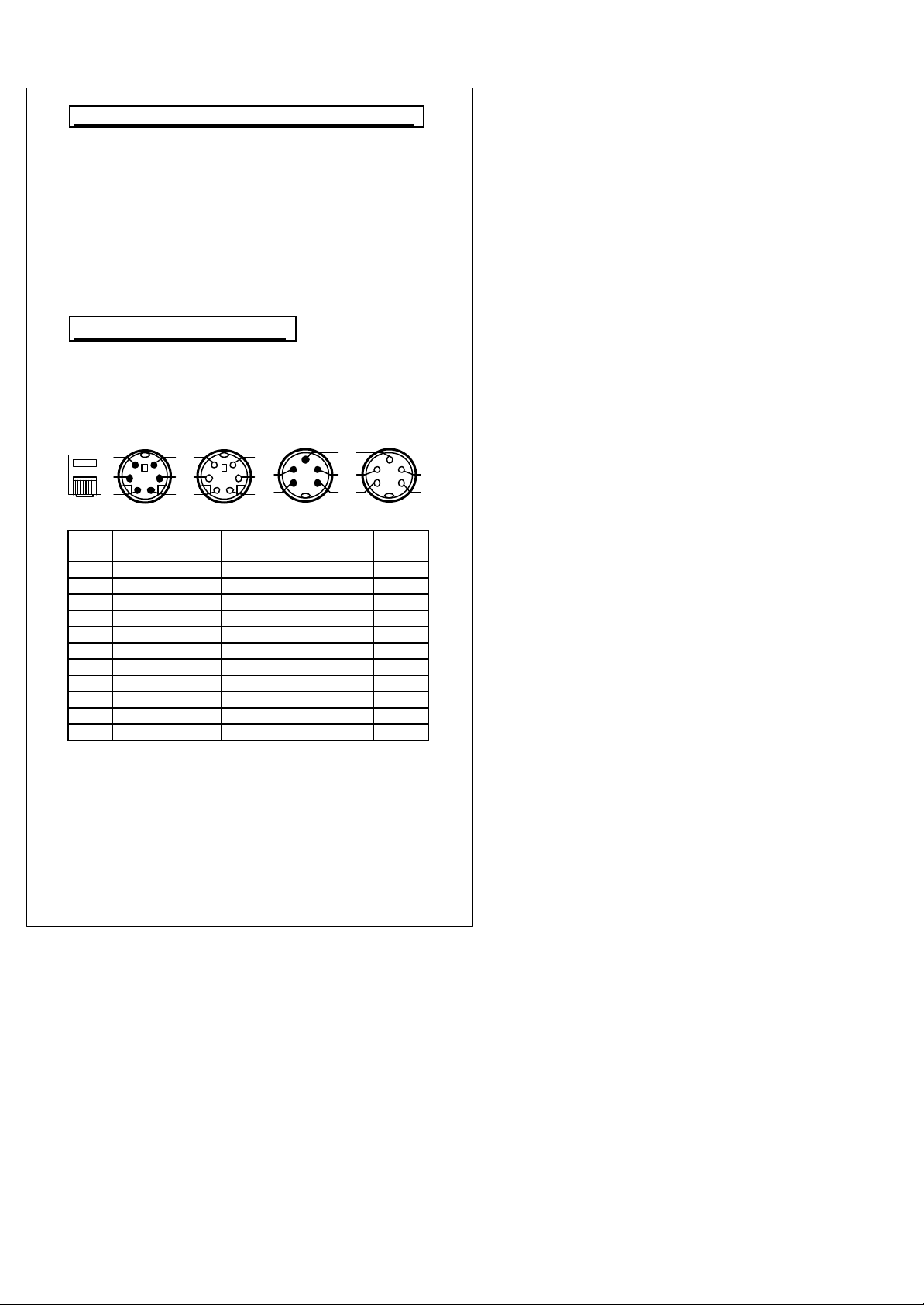
1. Keyboard Wedge:
A. 6 DIN and 5 DIN connector
M F M F
DIN-6M DIN-6F Function DIN-5M DIN-5F
Jack
1 3 3 GND 4 4
2 4 4 VCC 5 5
3 -- 5 K/B CLK -- 1
4 -- 1 K/B DATA -- 2
5 1 -- SYS DATA 2 -6 5 -- SYS CLK 1 -7 -- -- -- -- -8 -- -- -- -- -9 -- -- -- -- --
10 -- -- -- -- --
3 3 GND shield 4 4
5

Phone
1 3 4 2 5 6 1 3 4 2 5
1
14 25
13 6 5 9 1 6 5 9 1
2. RS-232 : 9 PIN and 25 PIN female RS-232 connector
9P 25P
Phone Jack 9 Pin (F) 25 Pin (F)
1 5.1 7.1 GND
2 9 16.25 VCC
3 -- -- K/B DATA
4 -- -- K/B CLK
5 -- -- SYS DATA
6 -- -- SYS CLK
7 7 4 CTS
8 2 3 TXD
9 3 2 RXD
10 8 5 RTS
5 7 GND Shield
3. WAND Emulation: 9 PIN female and 5 DIN?6 DIN
male connector
Function
9P M M
Jack
Remark
Dsub
9P (F)
Dsub
9P (M )
DIN-5M DIN-6M
1 GND 7.8 1 3 3
2 VCC 9 5 1 1
8 DATA 2 7 2 2
GND Shield 7 1 3 3
6
2 4 1 3 4 2 3 1
2 5 8
7
1 3
4
6 2 5 8 7 1 4 3 6
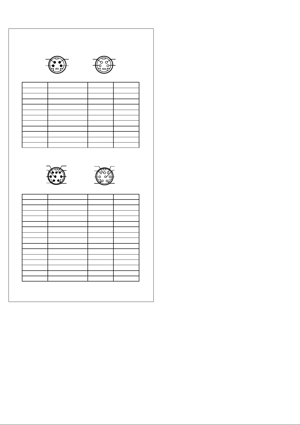
4. Apple MACINTOSH: 4 PIN female and 4 DIN male
M F
Phone Jack Function DIN-4M DIM-4F
1 GND 4 4
2 VCC 3 3
3 K/B DATA -- -4 K/B CLK -- -5 SYS DATA 1 1
6 SYS CLK -- -7 -- -- -8 -- -- -9 -- -- --
10 -- -- --
GND Shield 4 4
connector
5. NEC 9800: 8 PI N female and 8 DIN male connector
M F
Phone Jack Function DIN-8M DIM-8F
1 GND 2 2
2 VCC 8 8
3 K/B DATA -- 4
4 K/B CLK -- 3
5 SYS DATA 4 -6 SYS CLK 3 -7 -- -- -8 -- -- -9 -- -- --
10 -- -- --
Reset 1 1
Retry 5 5
-- 6 6
-- 7 7
GND Shield 2 2
7
6 5 9 1
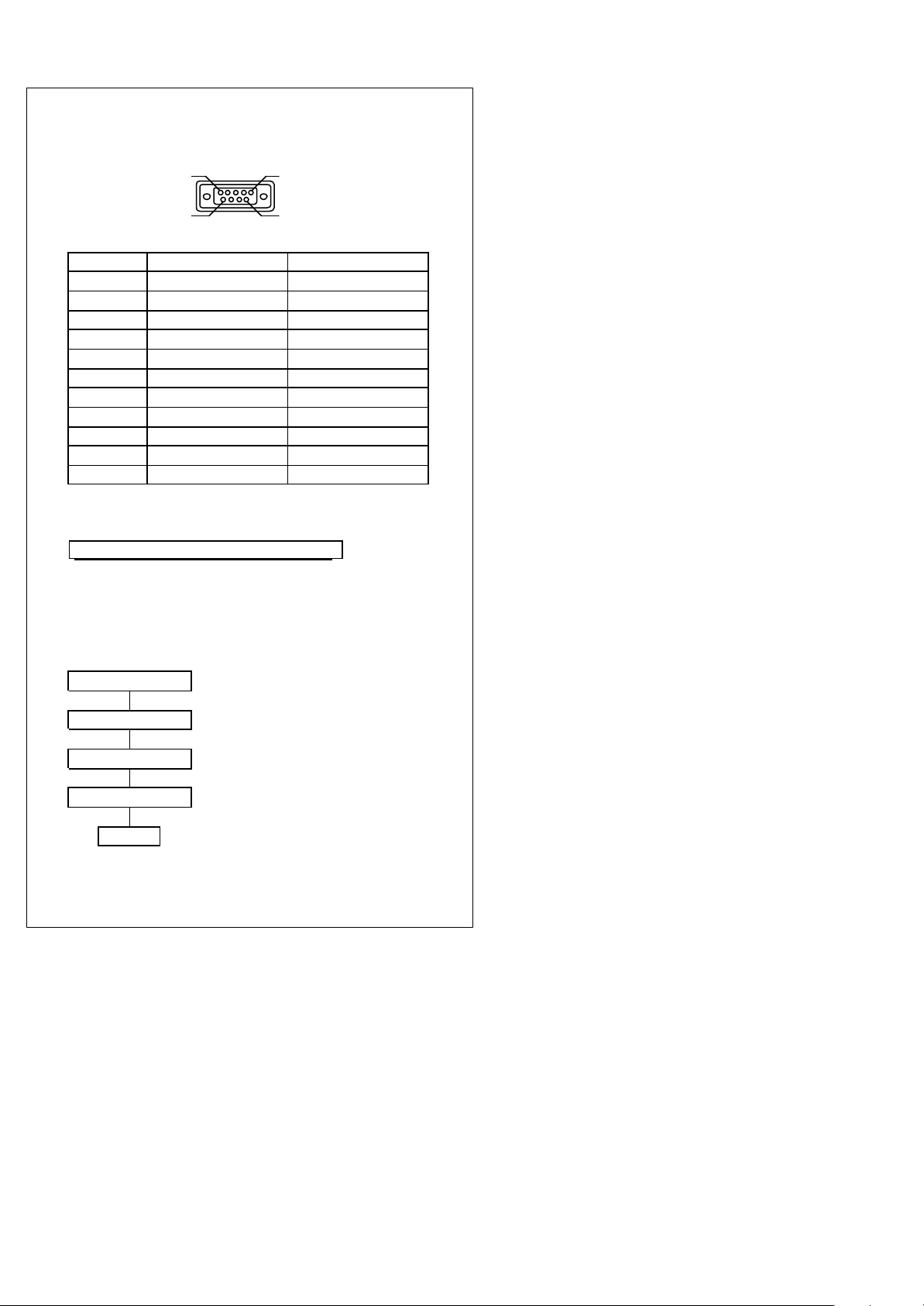
6. TTL (CMOS): 9 PIN female and 5 DIN?6DIN male
connector
9P
Phone Jack
1 GND 7
2 VCC+5V 9
3 DATA 1
4 INDICATOR 2
5 TRIGGER 3
6 ENABLE 4
7 SCAN 5
8 -- -9 -- --
10 -- --
GND Shield
Function Dsub 9P (F)
Chapter 4. Set Up Configuration
1. Example:
In order to setup the program for the bar code
reader, you must be familiar with the setup
procedure. Three examples are given below.
Example 1: Setup Code 39 refer page 21
Start ? Place command to CCD
Code 39 ON ? Turning on Code39 decoding
Full ASCII ? Code39 Full ASCII mode selected
Verify Checksum
END ? Setting procedure completed
?
Code39 mode 43
8
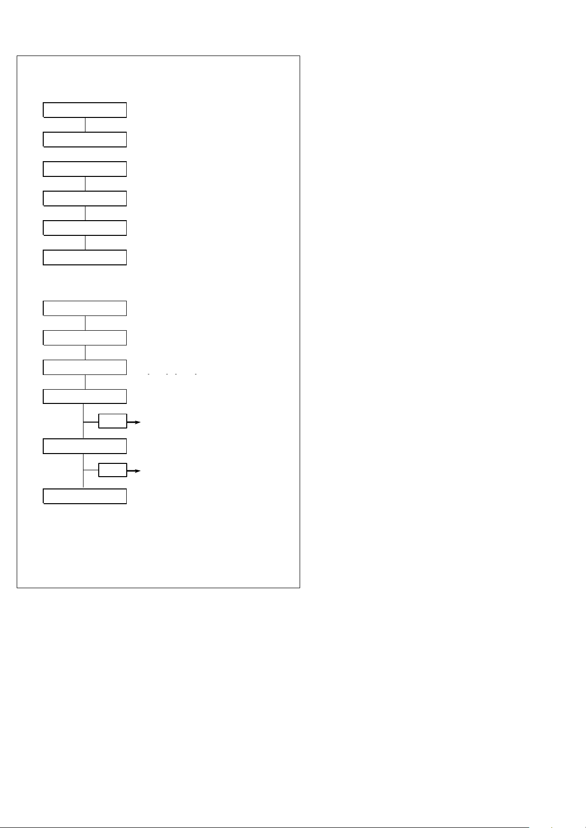
Example 2:
Start ? Place command to CCD
Flash mode ? Turning on Flash mode
Start ? Place command to CCD
Flash On/Off ? Turn on Flash on/off time setting
Appendix A "0",”6”
Appendix A "0",”A”
Example 3:
Start ? Place command to CCD
Interleaved 2 of 5 On
Define length ?
Appendix A "0", "A"
?
Setting Flash on 0.6 sec
?
Setting Flash off 1 sec
?
Turning on Interleaved 2 of 5
Define interleaved 2 of 5
?
Length with is equal to 10
SET Only length 10 is set
Appendix A "0", "C"
Appendix A "0", "E"
All Appendix A are no need to scan “END”
9
?
Length with is equal to 12
SET Both length 10 & 12 are set
?
Length with is equal to 14
All 3 length (10,12,14) are set
completely.
No need to scan “SET” again.
1. SET DEFAULT CONFIGURATION
Default
All programmed settings will be returned to the
manufacture default setting after the scanning process.
Other available option
Show configuration Show version
Abort setting
Start up code
If the scanner’s light is on, but it can not read. Try to
scan the “start up code”. The scanner may read again.
10

2. INTERFACE OPTIONS
Start
*Keyboard
AT Notebook
RS-232
WAND
End
Read the interface selection code for your particular
application.
Above interfaces, only one can be enabled, other
interfaces will be disabled automatically, ie, scan
“Start”? “RS232”? “End”.
Mute
If you scan “Mute”, the initial welcome music will be
on “Mute” mode when power on the terminal device
11

3. SYSTEM TYPE
Start
Apple Macintosh ADB PC XT
NEC 9800 *PC AT, PS/2 50 60 70 80
IBM 5550 PS/2 25 30
ACER 7300
End
Other system types may be available upon request,
please consult your supplier for details.
12

4. KEYBOARD WEDGE SETTING
Start
*On
Upper/Lower case
Upper *Lower
Number Keys
*Alphanum Number lock
Upper Caps Lock
*OFF ON
*OFF ON
13
Alt+Number
End

5. RS-232 SETTING
Start On
Baud Rate
1200 *9600
2400 19200
4800 38400
7 bit *8 bit
*Disabled Even
Odd
*Disabled Xon/Xoff RS232
Data Bits
Parity
RS-232 Hand
Shaking
End RTS/CTS RS232
14
 Loading...