

Page 1
TS SeriesTS
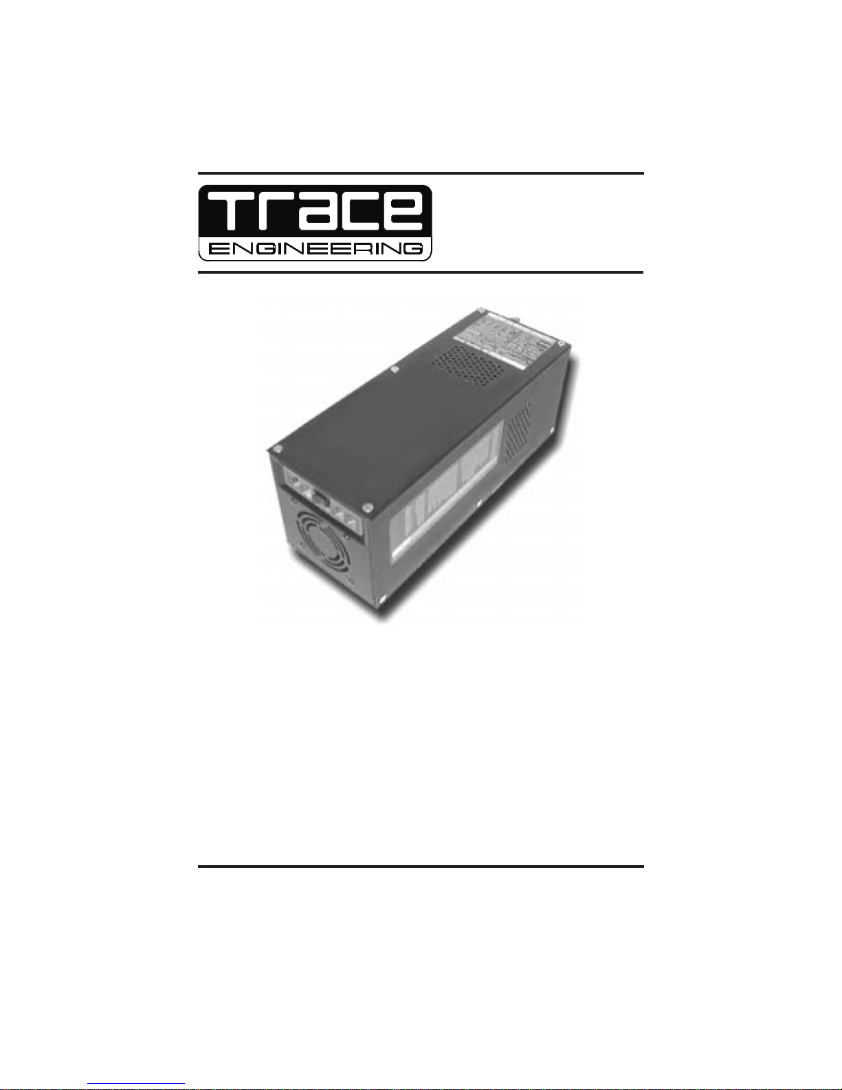
Introducing the TS Series Inverter
The Model TS Series microprocessor-controlled modified sinewave inverter converts DC
current into AC current. Rated at 400 to 800 watts continuous. Features include:
!
Power-saving Search mode
!
Easy installation
!
Battery voltage indicator
!
15-amp AC pass-thru circuit
!
User selectable low battery cutoff (LBCO)
!
Automatic transfer to inverter mode when AC supply is interrupted (with SB
option).
!
User selectable transfer sensitivity (with SB Option)
!
Optional dual 15-amp grounded AC outlet
!
Optional plug-in three-stage battery charger
!
Optional remote control
Copyright Trace Engineering Co. Inc. Tel (360) 435-8826 Part Number 3141
th
5916 195 Street, NE Fax (360)435-2229 Effective Date: July 15, 1998
Arlington, WA 98223 USA www.traceengineering.com Page
1
Page 2
Product Materials Package
Thank you for choosing Trace Engineering products to
meet your alternative-energy power needs. We make every
effort to ensure that your inverter/charger is properly
packaged for shipping and includes all the materials
requested. Every Trace inverter/charger is packaged with
the following materials:
Owner's Manual;
!
Trace bumper sticker;
!
If any of the above listed materials are missing from your
package, or if it is unsatisfactory in any manner, please
call Customer Service at 360-435-8826 or fax this page
with your comments to 360-435-2229.
Model Number:
Serial Number:
Comments:
Check out our web site at for
www.traceengineering.com
more information and answers to your FAQ's.
Copyright Trace Engineering Co. Inc. Tel (360) 435-8826 Part Number 3141
th
5916 195 Street, NE Fax (360)435-2229 Effective Date: July 15, 1998
Arlington, WA 98223 USA www.traceengineering.com Page
2
Page 3

IMPORTANT SAFETY INSTRUCTIONS
IMPORTANT SAFETY INSTRUCTIONS
SAVE THESE INSTRUCTIONS!
This booklet contains important instructions for Model TS Series that should be followed
during installation and maintenance of the unit.
General Precautions
Before using this device, read all instructions and cautionary markings on (a) the device,
(b) the batteries and (C) all appropriate sections of this instruction booklet. Refer to the
Battery Council International for installation and servicing instructions for batteries.
CAUTION - To reduce risk of injury, charge only deep-cycle lead acid, lead antimony, lead
calcium, gel cell, or absorbed-mat type rechargeable batteries. Other types of batteries
may burst, causing personal injury and damage.
Do not expose the device to rain, snow or liquids of any type. This device is designed for
indoor mounting only. Protect the device from splashing when used in vehicle applications.
Do not mount this device in unventilated enclosures or in an engine compartment.
Do not disassemble this device: take it to a qualified Trace Service Center when service or
repair is required. Incorrect re-assembly may result in a risk of electric shock or fire.
Before using this device, read all instructions and cautionary markings in this booklet and
on the equipment.
To reduce risk of electric shock, disconnect all wiring before attempting any maintenance or
cleaning. Turning off the device may not reduce this risk. As long as AC input power is
present, the charger section will be operable (if installed) regardless of the on/off switch
position. Solar modules produce power when exposed to light - disable or disconnect
before servicing any connected equipment.
WARNING - WORKING IN VICINITY OF A LEAD ACID BATTERY IS
DANGEROUS. BATTERIES GENERATE EXPLOSIVE GASES DURING
NORMAL OPERATION.
Provide ventilation to the outdoors from the battery compartment. Design the battery
enclosure to prevent accumulation of "pockets" of hydrogen gas at the top of the
compartment. Vent the battery compartment from the highest point.
No terminals or lugs are required for hook-up of the AC wiring. AC wiring must be no less
than 14 AWG (2.082 mm) copper wire and rated for 75C or higher. Battery cables must be
rated for 75C or higher and must be no less than #6 AWG.
Torque all AC wiring connections to 16 inch-pounds (1.8 N-m). Torque all DC cable
connections to 13 foot- pounds (157 inch-pounds) (17 N-m).
Special Notices
Tools required to make AC wiring connections: Wire strippers, Phillips screw driver #2,
slotted screw driver ¼" (6MM) blade, and a torque wrench.
This inverter is for use with a nominal battery-supply voltage of either 12-volt DC or 24-volt
DC. See unit label for appropriate voltage required.
For battery installation and maintenance: read the battery manufacturer's installation and
maintenance instructions prior to operating. Do not mount on or near flammable materials
(plywood, chemicals, gasoline, etc.)
Copyright Trace Engineering Co. Inc. Tel (360) 435-8826 Part Number 3141
th
5916 195 Street, NE Fax (360)435-2229 Effective Date: July 15, 1998
Arlington, WA 98223 USA www.traceengineering.com Page
3
Page 4
No AC or DC disconnects are provided as an integral part of this device. Both AC and DC
disconnects must be provided as part of the system installation, if required.
No over-current protection for the battery supply is provided as an integral part of this
device. Over-current protection of the battery cables must be provided as part of the
system installation.
No over-current protection for the AC output wiring is provided as an integral part of this
device. Over-current protection of the AC output wiring must be provided as part of the
system installation.
Caution: To reduce the risk of fire, use only input circuits provided with 20-ampere
branch circuit protection in accordance with the National Electrical Code,
ANSI/NFPA70.
DC GROUNDING INSTRUCTIONS - This device must be connected to a grounded,
permanent wiring system. For most installations, the negative battery conductor must be
bonded to the grounding system at one (and only one) point in the system. All US
installations must comply with national and local codes and ordinances.
AC GROUNDING INSTRUCTIONS The AC system in mobile installations must have the
neutral isolated from the grounding throughout the load distribution circuits.
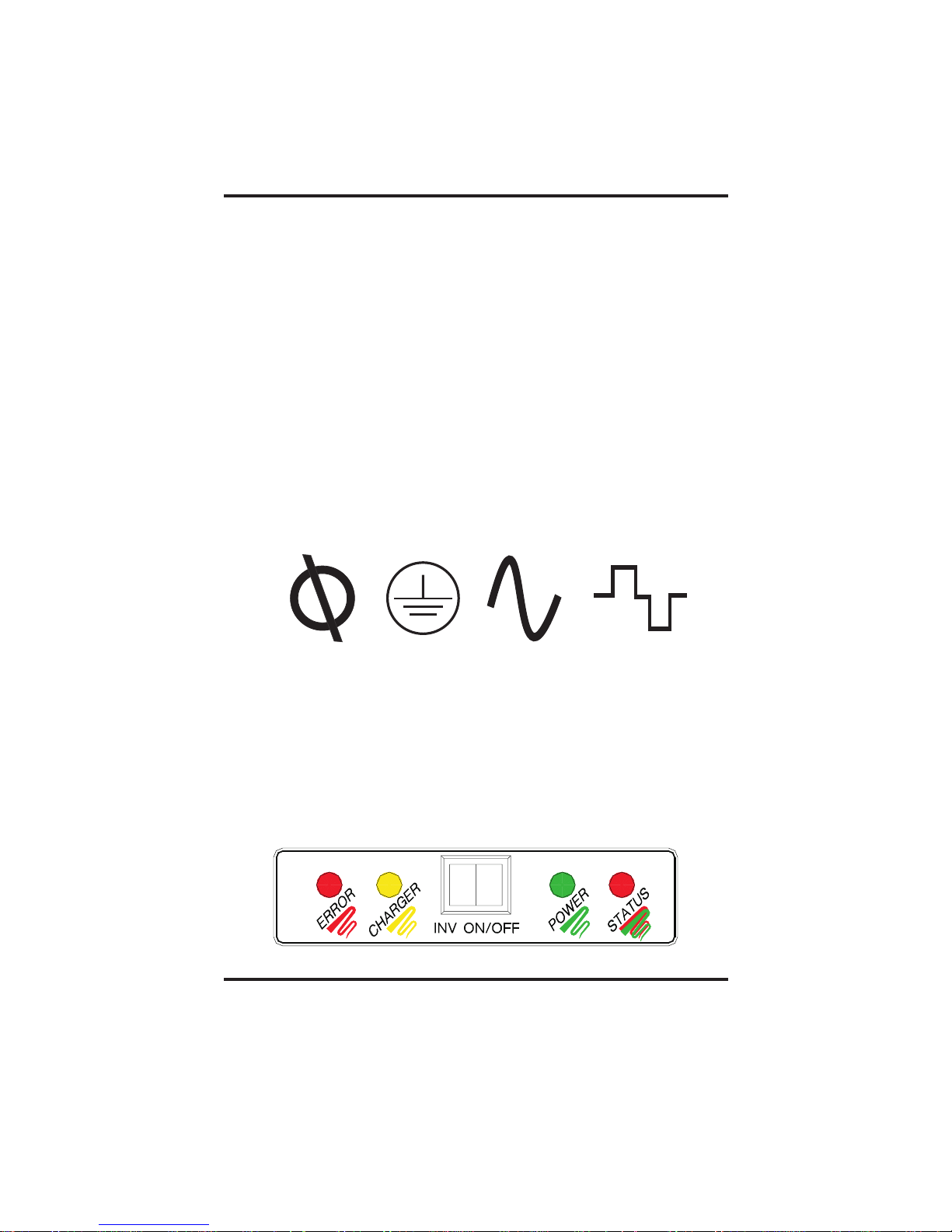
Symbols
Symbols used in this booklet and on the device itself are shown below:
Phase Chassis Ground AC Input AC Output
Controls and Indicators
The TS Series front panel features a power switch, four LEDs, and a fan on some models.
The back panel configuration varies depending upon options.
Front Panel Controls
The TS Series front panel controls and indicators include a momentary push-button Power
switch, a red error status indicator, a yellow charger status indicator, a green power light,
and a white battery status indicator.
Copyright Trace Engineering Co. Inc. Tel (360) 435-8826 Part Number 3141
th
5916 195 Street, NE Fax (360)435-2229 Effective Date: July 15, 1998
Arlington, WA 98223 USA www.traceengineering.com Page
4
Page 5

Inv On/Off Switch Operation
The momentary push-button switch on the front panel controls the operating mode of the
inverter:
Search: Push the Inv On/Off switch once to enable Search mode. The power lamp will
flash slowly in this mode. When in Search mode, the inverter emits a pulse testing the
output circuits for loads. If a load greater than eight watts is present on the output circuit,
the inverter turns On and provides AC power to the circuit for as long as the load is present,
automatically switching back to Search mode when the load is no longer present.
On
: When in Search mode, push the Inv On/Off switch once to turn the inverter to On
mode. The inverter will produce AC power from the batteries until the low battery cut-off
voltage is reached, or until the power switch is pressed once again.
When equipped with the optional battery charger, the device will remain in On mode until
approximately 20 seconds after AC power is applied, when it will stop inverting, pass
through the current, and begin charging.
Off
: When in On mode, press the On/Off switch once to turn the inverter Off. The inverter
draws very little power when in Off mode.
LED Indicators
The front panel features four LEDs which operate in the following manner:
q
Error : - Low battery error; indicates
q
Charger: - AC is present but inverter has not
q
Power: - inverter is in Search mode.
q
Status: - battery voltage exceeds 12.8 (25.6 for 24-volt)
Slow Flash: (One per second)
battery voltage is below low battery cutoff (LBCO)..
Fast Flash: (5/sec)
voltage has exceeded 15.1 volts for about 25 seconds.
Steady Red
exceeds rated capacity.
Slow Flash: (1/sec)
transferred to charge mode.
Fast Flash: (10/sec)
mode.
Steady Yellow
Slow Flash: (1/sec)
Steady Green
Flickering: inverter is charging.
Off
- inverter is off.
Steady Green
Fast Green Flash: (10/sec)
Slow Green Flash: (1/sec)
Slow Red Flash: (1/sec)
Fast Red Flash: (10/sec)
Steady Red
- High battery error; indicates battery
- Overload error; lights steadily when load
- charger is charging in bulk/absorption
-charger is charging in float mode.
- AC is present on output.
- 12.5 to 12.7 volts (25.0 to 25.5)
- 12.3 to 12.4 volts (24.6 to 24.9)
- 12.0 to 12.2 volts (24.0 to 24.5)
- 11.8 to 11.9 volts (23.6 to 23.9)
- less than 11.8 volts (23.6 volts for 24-volt system)
Installation
Before beginning the installation, disconnect any power supply that you will be connecting
to this device. This section describes mounting, installation, and cabling,
Mounting
Mount this device on a shelf or table in a clean, dry, well-ventilated location close to the DC
supply. DO NOT locate this device in the same enclosure with batteries. Liquid lead-acid
batteries may produce explosive gases and must be well ventilated. Sealed batteries may
be located in the same enclosure. Allow adequate clearance around this device for proper
ventilation.
Copyright Trace Engineering Co. Inc. Tel (360) 435-8826 Part Number 3141
th
5916 195 Street, NE Fax (360)435-2229 Effective Date: July 15, 1998
Arlington, WA 98223 USA www.traceengineering.com Page
5
Page 6

DC Cabling
Use #6 AWG battery cables, Cables are available in 3, 5,
and 10 foot lengths (BC3, BC5, BC10). Strip the
insulation about ½“ (12 mm) from the end of each wire.
Using a Phillips screwdriver, remove the six screws from
the top and side of the inverter and remove the cover.
Loosen the uppermost strain relief by rotating the cap
counter-clockwise, and insert the stripped end of the
the cable lug marked ”Battery Plus” on the PCB. Using a straight-blade screwdriver,
tighten the screw in the lug to 12 foot-pounds, then tighten the strain relief. Repeat for the
Battery Minus (-) cable. Replace the cover and reinstall the cover screws.
positive (+) battery cable through the strain relief and into
AC Cabling
On AC outlet equipped models, just plug-in the load or appliance to the pre-wired outlet on
the back panel of the inverter. On units equipped with a factory-installed battery charger,
wire the AC input circuit to the charger board as shown in the section of this
booklet (some configurations may include a pre-wired AC line cord).
Options
User Configuration Options
The standard TS series inverter requires no user configuration. When you have the
standby battery charger option or the PV controller option, you can configure the TS Series
for your specific system requirements. Configuration options include battery discharge
voltage (LBCO), AC voltage transfer sensitivity, and battery type. To change configurations,
disconnect any AC or DC power supply and loads from the unit and remove the cover from
the chassis. Remove or install the jumpers from the configuration pins as shown in the
illustration at right. If the unit is equipped with the SB charger option or the PV option, it
may be necessary to remove the option board to gain access to the configuration jumpers.
See the illustration on Page 9 to locate the configuration pins on the main printed circuit
board (PCB)
Jumper
On
Off
Discharge
You can set the inverter to stop inverting when the battery to which it is connected has been
discharged to 11.7 volts for 5 minutes (shallow discharge) or to 10.6 volts for one minute
(deep discharge). The factory setting is Deep discharge Shallow discharge means less
battery stress and more charge/ cycles. Deep discharge allows the batteries to be
discharged almost completely. This usually results in somewhat shorter battery life, but
fewer charge/discharge cycles. To select Shallow Discharge, remove the jumper from the
configuration pins. For Deep Discharge, the two pins must be connected by the jumper.
Pins
Depth
Transfer Sensitivity (SB Option Only)
The TS inverter can be configured to begin inverting whenever grid voltage falls to 95 volts
RMS (UPS mode) or to delay transfer until line voltage falls to 80 volts RMS (Gen mode).
The factory default, UPS mode, is relatively intolerant of line voltage fluctuations to prevent
A jumper is a small, rectangular piece of plastic with two square
holes in it that fit over two pins as shown in the illustration at left.
A jumper contains an internal conductor that joins the two pins,
completing a circuit. When the jumper is removed, the circuit is
interrupted. Jumpers are often used for changing configuration
parameters. When a jumper is not connecting two pins, it can be
stored by slipping it over just one of the pins instead of both. This
will have no effect upon the configuration, but will keep the
jumper handy for future use.
Copyright Trace Engineering Co. Inc. Tel (360) 435-8826 Part Number 3141
th
5916 195 Street, NE Fax (360)435-2229 Effective Date: July 15, 1998
Arlington, WA 98223 USA www.traceengineering.com Page
6
Page 7

computer brownouts, and is preferred when operating devices that are sensitive to voltage
fluctuations. GEN mode is preferred when line voltage is provided by a generator, some of
which provide AC power with significant fluctuations in RMS voltage. To select UPS mode,
connect the two pins with the jumper provided. For Gen mode, remove the jumper from the
pins. Store the jumper by leaving it on one pin only. Transfer time from grid to inverter is
about 8 to 12 milliseconds.
DEEP > 10.6 V
SHALLOW > 11.7 V
UPS = 95V RMS
GEN = 80V RMS
DC
DC
AC
AC
SEALED FLOODED
14.3 14.7 Bulk Volts
60 min 60 min Absorption Time
13.6 13.4 Float Volts
Battery Type (SB Option Only)
The TS Series can charge either liquid lead-acid (flooded) batteries or sealed, gel or
absorbed glass batteries. The difference is in the charge voltages. The unit comes from
the factory pre-configured for sealed batteries. To change to flooded batteries, remove the
jumper from the pin pair labeled Sealed/Flooded.
Selecting the Best Battery
There are many types and sizes of batteries available, including starting, deep-cycle,
sealed gel, and absorbed glass mat. Which battery is best for your installation depends
upon your unique circumstances. In order to help you choose, a discussion of these types
of batteries is found in this section.
Starting Batteries
Starting batteries are designed for high cranking power, not deep cycling. Don't use them.
Deep Cycle Batteries
This type of battery is best suited for use with inverters because they tolerate a greater
depth-of-discharge before being recharged. The most common type is the non-sealed,
liquid-electrolyte battery, which have removable cell caps for monitoring the electrolyte
level. When a cell is low, add only distilled water. Check the electrolyte level at least
monthly. Top-up after recharging.
A popular and inexpensive deep-cycle battery is the six-volt golf cart battery rated at 220
amp-hours. These can be cycled repeatedly to 80% of their capacity without damage. The
TS512 is a 12-volt system, therefore you must connect at least two of these batteries in
series in order to produce 12 volts. The TS524 is a 24-volt system and required four of
these batteries.
Some systems use the L16 type of battery: six-volt batteries rated at 350 amp-hours
available from a number of manufacturers. At 17 inches in height and up to 130 pounds
each, they may be difficult to place in mobile or marine installations.
Type 8D batteries are available in either starting or deep-cycle construction. Most common
are the starting version used to start very large truck engines. Make sure you purchase the
deep-cycle version. These deep-cycle versions are 12-volts and are rated at 200 amp
hours or so. Type 4D batteries are very similar in construction, but about one-third smaller.
Copyright Trace Engineering Co. Inc. Tel (360) 435-8826 Part Number 3141
th
5916 195 Street, NE Fax (360)435-2229 Effective Date: July 15, 1998
Arlington, WA 98223 USA www.traceengineering.com Page
7
Page 8

Sealed Gel Cell
Sealed gel cell batteries do not use battery caps because the electrolyte is in the form of a
gel. This allows the batteries to be mounted in any position without spilling. Other
advantages are: no maintenance, long life (800 cycles claimed) , and low self-discharge.
The disadvantage is high initial cost and the possibility of damage from overcharging. Don't
confuse sealed batteries with maintenance-free batteries - the latter are typically standard
liquid electrolyte batteries with no caps for adding water; when the electrolyte gets low you
replace the battery. For best results, use the Battery Temperature Sensor (BTS) option with
sealed batteries.
Monthly Maintenance
Check the level of the electrolyte in each battery at least once a month. It must be above
the top of the plates, but not completely full. Most batteries have a split plastic cup under
the caps, which the electrolyte should just touch when full. Don't overfill the batteries, or
the electrolyte will spill out of the batteries when recharging. Refill batteries with distilled
water only - "spring" water and regular tap water may have high levels of minerals that can
poison the battery chemistry and reduce battery life.
Check the battery cable connectors for tightness and corrosion. To remove corrosion,
disconnect the cables and carefully rinse with a mild solution of baking soda and water. DO
NOT ALLOW THE SOLUTION TO ENTER THE BATTERY. Rinse the top of the battery
with clean water when finished. Remove stubborn corrosion with a wire brush. Any
automotive parts store will have a wire brush tool specifically designed for cleaning cable
lugs and battery terminals.
To prevent corrosion from forming on the battery terminals and cable lugs, coat them (only
after installing the cables) with liquid neoprene or anti-corrosion grease available from any
quality marine, automotive or battery equipment supplier. Do not apply any material
between the terminal and the cable lugs - the connection must be metal-to-metal. Apply
the protective coating only after the bolts are tight.
Inter-Battery Cabling
Batteries may be connected in series, in parallel, or both depending upon your purpose.
To increase voltage, connect two or more batteries in series as shown in the diagram
below. The voltage of the combined batteries will be the sum of the voltage of all the
batteries. The amp-hour capacity will remain unchanged. To increase amp-hour capacity,
connect two or more batteries in parallel as shown in diagram B. The amp-hour capacity of
the combined batteries will be the sum of each individual battery, but the voltage will remain
unchanged.
A. Series Cabling:
6-volt + 6-volt = 12 volt.
B. Parallel Cabling:
220 ah + 220 ah = 440 ah
Copyright Trace Engineering Co. Inc. Tel (360) 435-8826 Part Number 3141
th
5916 195 Street, NE Fax (360)435-2229 Effective Date: July 15, 1998
Arlington, WA 98223 USA www.traceengineering.com Page
8
Page 9

White = Neutral
Remove AC routing wire
to install option board
Green = Ground
Black = Hot
Configuration
pins
OUTAC
White
Green
Black
SB Option
PCB
RED (+)
BLACK ( )−
BTS
BTS
Jack
INAC
White
Green
Black
Jack
RC8
RC8
Jack
Jack
Remove plug and install circuit breaker
connect black wires to circuit breaker
Options
Field-installed options for the TS Series include either a three-stage standby battery
charger (SB option), a battery temperature sensor (BTS option), and a remote control (RC8
option).
Standby Battery Charger
The Stand-By (SB) charger option features a three-stage automatic battery charger with AC
pass-through relay mounted on a PCB that can be field installed, includes an AC power
supply cord and circuit breaker, and enables transfer sensitivity, battery selection, and
depth of discharge.
Battery voltage is varied during the three stage battery charging process, as follows:
BULK
-During this initial stage of charging, the Charge LED flashes about once each
second and the inverter charges at a constant current. This causes the battery voltage to
rise over time. When battery voltage reaches the bulk voltage setting (see
Configuration Options
for voltage settings), the charger begins the absorption stage of
charging.
ABSORPTION
-During this phase, the charge current gradually reduces while the battery
voltage is held constant for two hours at the bulk voltage During the ABSORPTION stage,
the Charge LED flashes rapidly.
User
Copyright Trace Engineering Co. Inc. Tel (360) 435-8826 Part Number 3141
th
5916 195 Street, NE Fax (360)435-2229 Effective Date: July 15, 1998
Arlington, WA 98223 USA www.traceengineering.com Page
9
Page 10

Charging
Started
Absorption StageBulk Stage
Bulk Voltage
Float Stage
Float Voltage
DC Voltage
DC&ACCurrent
Max Charge
Amps Setting
Constant Current
80-90% Capacity
Tw o-Hour Ab sorption Period
Constant Voltage
100% capacity
Reduced Current and Voltage
FLOAT - During this stage the voltage of the battery is held at the FLOAT voltage setting.
Full current from the PV array can be provided to the loads connected to the battery during
the float stage. When the battery voltage has reached the FLOAT stage, the status LED
will be steady green.
When the battery voltage drops below the FLOAT setting for a cumulative period of one
hour, a new BULK cycle will be triggered. This typically occurs each night. If the battery
is full at the start of the day, it will receive an ABSORPTION charge for one hour and then
be held at the FLOAT setting for the remaining period of the day. Should the battery
voltage drop below the FLOAT setting for a cumulative period of one hour, another BULK
and ABSORPTION cycle will be initiated.
This three-stage charging process results in faster charging compared to on-off relay type
or constant voltage solid-state regulators. The final FLOAT voltage setting reduces battery
gassing, minimizes watering requirements and ensures the complete battery recharging.
Warning: Do not connect the AC power cord to
the AC out terminal. You may damage the unit.
Inverter to Charger Transition
On inverter models equipped with the three-stage internal standby battery charger, the
charger and an automatic transfer relay allows operation as either a battery charger or an
inverter, (but not both at the same time). An external source of AC power (e.g. shore
power, generator, and/or utility grid) must be supplied to the inverter AC input in order to
allow it to operate as a battery charger. As long as AC power is supplied to the charger, it
operates regardless of the position of the On/Of switch. When operation as a charger, the
inverter’s AC output is provided by the external source.
The inverter automatically becomes a battery charger after a 10-second delay whenever
AC power is supplied to it. This delay is built-in to provide time for a generator to spin-up to
a stable voltage and avoid relay chattering.
Copyright Trace Engineering Co. Inc. Tel (360) 435-8826 Part Number 3141
th
5916 195 Street, NE Fax (360)435-2229 Effective Date: July 15, 1998
Arlington, WA 98223 USA www.traceengineering.com Page
10
Page 11

The inverter’s AC input connects internally to the inverter’s AC output while in the battery
charger mode. A 15-amp pass-through relay accomplishes this switching, protected by a
15-amp circuit breaker.
Battery Temperature Sensor
An optional battery temperature sensor (BTS) can be fieldinstalled at anytime. Remove the lid of the chassis as described
in the Optional Standby Battery Charger section. At the bottom
right-hand edge of the TS board are two RJ11 plug jacks. The
top-most jack is labeled ‘BTS.’ Remove one of the 7/8 -inch
knockout plugs in the chassis endplate and install the BTS
through this opening and plug it into this jack. Sandwich the
BTS sensor between any two of the batteries in your system.
The BTS will enable the SB charger to ‘fine tune’ the charging
voltage based on temperature and lengthen battery life
RC8 Remote On/Off Switch
The optional RC8 remote control unit duplicates the Power On/Off Switch on the
inverter/charger and is coupled to the inverter. It connects directly to the six-conductor RJ15
phone jack labeled RC8 on the bottom right of the inverter PCB (see illustration on Page
9). Use the Trace remote cable provided with the RC8 because it is tin-plated stranded
cable with gold-plated connectors.
The front panel of the RC8 also shows the status of different modes of the inverter. The red
LED on the front directly mimics the green LED on the inverter/charger. The following
indications are shown by the RC8:
0
Steady Red: unit is in inverter or charger(if installed) mode
0
Slow blinking Red (1-3 flashes): unit is in search mode
0
Rapidly blinking Red : indicates overcurrent condition. Unit will shut Off after
8-12 seconds of an overcurrent condiition.
RC8 Remote Installation
Cut a 1-7/8" diameter hole. At least 1½" of clearance is required behind the hole. Next drill
the two holes needed to screw the installation to the wall. After routing the Trace remote
cable, plug it into the six-conductor, RJ15 phone jack on the TS main PCB.
Copyright Trace Engineering Co. Inc. Tel (360) 435-8826 Part Number 3141
th
5916 195 Street, NE Fax (360)435-2229 Effective Date: July 15, 1998
Arlington, WA 98223 USA www.traceengineering.com Page
11
Page 12

Rear Panel Configuration
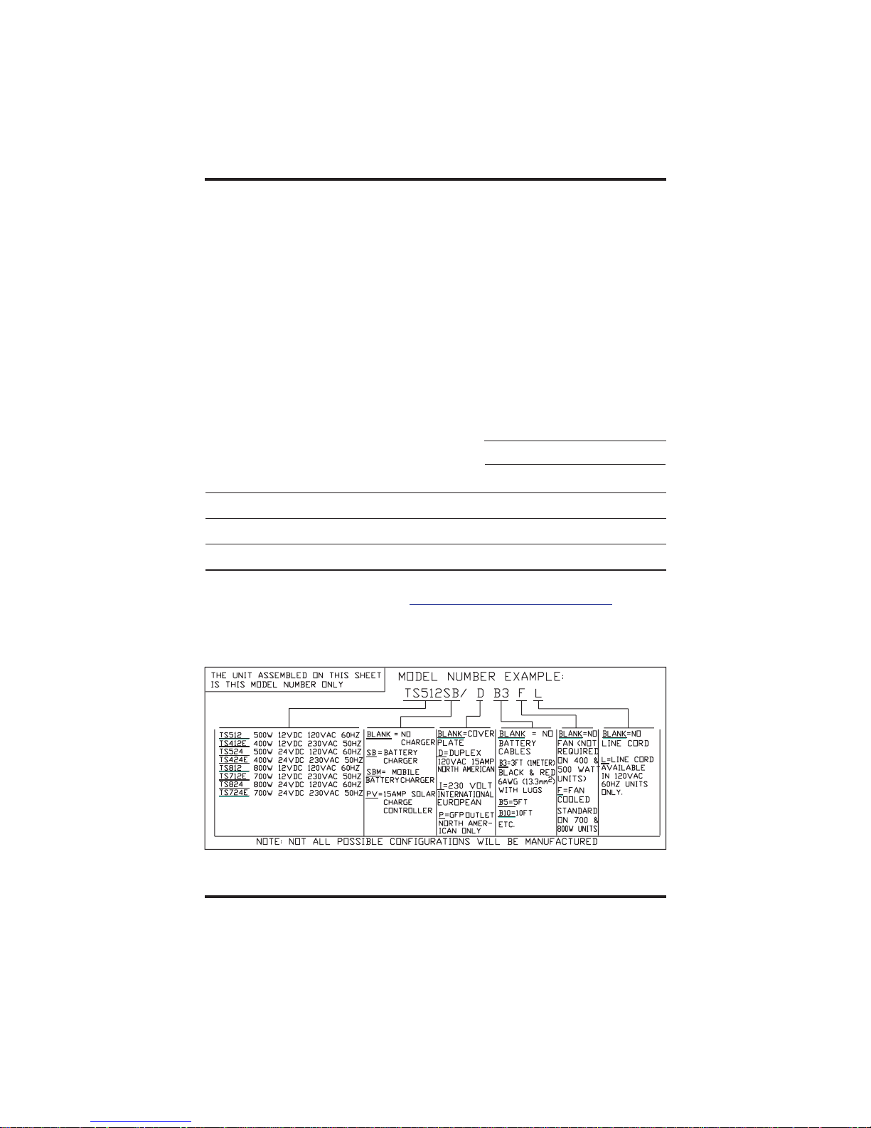
The TS series rear panel configuration is determined by the model and options selected.
Some models will have one or more of the features listed below:
0
Duplex Outlet Option (D): a 120-volt, 15-amp
models.
0
Duplex Outlet Option (I):
on some models.
0
GFCI Outlet Option (P): Ground Fault Circuit Interrupt outlet is required on
some U.S. models.
0
Outlet plate: blank plate provided when no outlet is installed, AC Out cable
must be hardwired to the TS PCB as shown in these instructions.
0
15-amp input circuit breaker provided as part of the standby battery charger
option.
0
AC-In Power Cord Option (L): 14/3 120-volt AC stranded-copper power cable
with molded standard U.S.. plug provided only with standby battery charger
option.
0
Battery Cable Option (B#): #6 AWG stranded copper cable, insulated with black
(negative) or red (positive) vinyl for polarity identification. Available in three, five
or 10 foot lengths. Specify BC3, BC5, or BC10
0
Zinc strain relief: provided only with standby charger option.
230-volt, 15-amp for export models outlet is provided
outlet is provided on some
End panel showing optional
duplex outlet, AC supply cord,
and SB option circuit breaker
.
Circuit Breaker (provided with
SB option) Press to reset
Copyright Trace Engineering Co. Inc. Tel (360) 435-8826 Part Number 3141
th
5916 195 Street, NE Fax (360)435-2229 Effective Date: July 15, 1998
Arlington, WA 98223 USA www.traceengineering.com Page
Chassis Ground:
connect to earth
ground and/or battery
negative.
AC-In power cord for SB charger option
12
Page 13

models
24-volt
for
Float
kg)
mm)
lbs (10.4
X 136.525
on 25 centigrade)°
(based on 25 centigrade)°
(based
Model 412E 424E 512 524 712E 724E 812 824
Model 412E 424E 512 524 712E 724E 812 824
amps n/a n/a 16@1ms n/a n/a n/a n/a n/a
v/a 400 400 500 500 700 700 800 800
current
Power v/a 400 400 500 500 700 700 800 800
Surge current amps n/a n/a 16@1ms n/a n/a n/a n/a n/a
Power
Surge
Efficiency 92% 95% 92% 95% 92% 94% 90% 92%
Peak Efficiency 92% 95% 92% 95% 92% 94% 90% 92%
Peak
all models
for
amps .25a .50a .25a .50a .25a .50a .25a
Watt
amps 17a 43a 21a 60a 30a 70a 35a
Mode ~1
Power 34
Current
Idle @12.6v/25.2v .50
Rated
Search
Input
In Search Mode ~1 Watt for all models
At Idle @12.6v/25.2v .50 amps .25a .50a .25a .50a .25a .50a .25a
At Rated Power 34 amps 17a 43a 21a 60a 30a 70a 35a
In
At
At
DC Input Current
DC
VdC 10-15 20-30 10-15 20-30 10-15 20-30 10-15 20-30
Volts 12 24 1224 12 2412 24
VAC) 230 230 120 120 230 230 120 120
DC
Range
Input
Voltage
Voltage
Nominal Input DC Volts 12 24 12 24 12 24 12 24
Input Voltage Range VdC 10-15 20-30 10-15 20-30 10-15 20-30 10-15 20-30
Output Voltage VAC) 230 230 120 120 230 230 120 120
Input
Output
Nominal
models
All models
all
watts
ññ ññ ññññ
ñ
ññ ññ ññññ
ñ
Regulation 0.04%
Regulation 6% 6% 6% 6% 6% 6% 6% 6%
Sense ~8
Voltage Regulation 6% 6% 6% 6% 6% 6% 6% 6%
Frequency Regulation 0.04% all models
Load Sense ~8 watts All models
Voltage
Frequency
Load
- 23.4
/21.2
models
12-volt
all models
for
AC for
- 11.7
amps
Cutoff 101.6
Battery
Relay 15
Low
Auto Low Battery Cutoff 101.6 - 11.7 for 12-volt models /21.2 - 23.4 for 24-volt models
Transfer Relay 15 amps AC for all models
Auto
Transfer
dc 15 8 15 8 25 13 30 15
cooling option option option option yes yes yes yes
Rate amps
fan
Charge
Internal fan cooling option option option option yes yes yes yes
Max Charge Rate amps dc 15 8 15 8 25 13 30 15
Max
Internal
X 139.7mm
Bulk, Absorption,
(355.6mm
D
Stage:
lbs (7.71kg) 23
W X 5.375”
X 5.5”
H
Dimensions 14“ H X 5.5” W X 5.375” D (355.6mm X 139.7mm X 136.525 mm)
Dimensions 14“
Weight 17
Shipping Weight 17 lbs (7.71kg) 23 lbs (10.4 kg)
Shipping
Profile 3
Charge Profile 3 Stage: Bulk, Absorption, Float
Charge
SPECIFICATIONS
SPECIFICATIONS
Copyright Trace Engineering Co. Inc. Tel (360) 435-8826 Part Number 3141
th
5916 195 Street, NE Fax (360)435-2229 Effective Date: July 15, 1998
Arlington, WA 98223 USA www.traceengineering.com Page
13
Page 14

Troubleshooting
Symptoms Problem Remedy
No AC power output AC routing wire disconnected reconnect wire See page 9
No warning LED’s
Battery voltage at the inverter's Check voltage, fuses or
terminals is too high or low breakers,cable connections
No power output Load too small for Search
Search LED flashing circuit to detect turn unit on
slowly
Power output LED Overload Remove or reduce loads
Flashing rapidly allow inverter to cool
or erratically before restarting
Power output is low Low battery
inverter
on and off and on Loose or corroded battery - Check and clean connections
Inverter shuts down Output of inverter wired back
after 20 seconds its own input output wiring
Charger is inoperative AC input voltage does not Check AC input for proper
Low charge rate Low AC input voltage Use larger generator, speed up
turns loads and recharge
Mode
connections
Loose AC output Check all AC output
connections
to
match inverter spec voltage and frequency of your
Charger voltage Refer to owner's manual for
improperly set
peak
(164 volts peak required for generator, check AC input
full charger output) wiring size cable too
AC current output of generator
too small to handle load
defeat search mode,
Check condition of batteries
connections
Check for proper AC input and
120 VAC models need
model,
>90 VAC to operate.
proper setting
too long
Reduce loads
small or
Low surge power Weak batteries, battery Refer to cable and battery
Error LED on steady Overload Let unit cool down,
No power at SB Charger relay stuck Have unit serviced
charger terminals
Copyright Trace Engineering Co. Inc. Tel (360) 435-8826 Part Number 3141
th
5916 195 Street, NE Fax (360)435-2229 Effective Date: July 15, 1998
Arlington, WA 98223 USA www.traceengineering.com Page
too small or too long mendations in owner's
cables recom
manual
reduce loads
14
Page 15

Warranty
Limited 2 Year Warranty
NOT FOR USE WITH LIFE SUPPORT EQUIPMENT
Trace Engineering Company warrants its power products against defects in
materials and workmanship for a period of two (2) years from the date of
purchase and extends this warranty to all purchasers or owners of the product
during the warranty period. Trace does not warrant its products from any and all
defects: (1) arising out of material or workmanship not provided by Trace
Engineering, or (2) resulting from abnormal use of the product or use in violation
of the instructions, or (3) in products repaired or serviced by other than Trace
Engineering repair facilities, or (4) in components, parts, or products expressly
warranted by another manufacturer. Trace Engineering agrees to supply all parts
and labor or repair or replace defects covered by this warranty with parts or
products of original or improved design, at its option, if the defective product is
returned to any Trace Engineering authorized warranty repair facility or to the
Trace Engineering factory in the original packaging, with all transportation costs
and full insurance paid by the purchaser or owner.
No equipment will be accepted without a Return Merchandise Authorization
(RMA). Call Customer Service at 360-435-8826 or FAX 360-435-2229 (email:
www.traceengineering.com)to obtain an RMA and shipping instructions.
ALL REMEDIES AND THE MEASURE OF DAMAGES ARE LIMITED TO THE
ABOVE. TRACE ENGINEERING SHALL IN NO EVENT BE LIABLE FOR
CONSEQUENTIAL, INCIDENTAL, CONTINGENT OR SPECIAL DAMAGES,
EVEN IF TRACE ENGINEERING HAS BEEN ADVISED OF THE POSSIBILITY
OF SUCH DAMAGES. ANY AND ALL OTHER WARRANTIES EXPRESSED OR
IMPLIED ARISING BY LAW, COURSE OF DEALING, COURSE OF
PERFORMANCE, USAGE OF TRADE, OR OTHERWISE, INCLUDING BUT
NOT LIMITED TO IMPLIED WARRANTIES OF MERCHANTABILITY AND
FITNESS FOR A PARTICULAR PURPOSE, ARE LIMITED IN DURATION TO A
PERIOD OF TWO (2) YEARS FROM THE DATE OF PURCHASE.
SOME STATES DO NOT ALLOW LIMITATIONS ON HOW LONG AN IMPLIED
WARRANTY LASTS, OR THE EXCLUSION OF INCIDENTAL OR
CONSEQUENTIAL DAMAGE. SO THE ABOVE LIMITATIONS MAY NOT APPLY
TO YOU. THIS WARRANTY GIVES YOU SPECIFIC LEGAL RIGHTS. YOU
MAY ALSO HAVE OTHER RIGHTS WHICH VARY FROM STATE TO STATE.
Copyright Trace Engineering Co. Inc. Tel (360) 435-8826 Part Number 3141
th
5916 195 Street, NE Fax (360)435-2229 Effective Date: July 15, 1998
Arlington, WA 98223 USA www.traceengineering.com Page
15
Page 16

Copyright Trace Engineering Co. Inc. Tel (360) 435-8826 Part Number 3141
th
5916 195 Street, NE Fax (360)435-2229 Effective Date: July 15, 1998
Arlington, WA 98223 USA www.traceengineering.com Page
16
 Loading...