

Page 1

Truck Series 770K Kit
for Volvo Trucks
Installation Guide
1999 Trace Engineering P/N 976-0001-00-01 Rev. A 10/99
Page 2

Page 3

Truck Series 770K Kit
Truck Series 770K Kit
Installation Guide
T able of Contents
Section Description Page
1. Installation ................................................................. 1
2. Service Information...................................................... 9
3. Warranty ....................................................................... 10
1999 Trace Engineering
i
Page 4

Truck Series 770K Kit
IMPORT ANT SAFETY INSTRUCTIONS
This manual contains important safety instructions that should be followed
during the installation and maintenance of this product.
To reduce the risk of electrical shock, and to ensure the safe installation and
operation of this product, the following safety symbols have been placed
throughout this manual to indicate dangerous conditions and important safety
instructions.
WARNING - A dangerous voltage or condition exists in this area.
CAUTION - This procedure is critical to the safe installation or
NOTE - This statement is important. Follow instructions closely.
• All electrical work must be done in accordance with local, national,and/or
international electrical codes.
• Before installing or using this device, read all instructions and cautionary
markings located in (or on) the manual, the batteries, and the inverter.
• Do not expose this unit to rain, snow or liquids of any type. This product is
designed only for indoor mounting.
• To reduce the chance of short-circuits when installing or working with
the inverter or the batteries, use insulated tools.
• Remove all jewelry such as rings, bracelets, necklaces, etc., while installing
this system. This will greatly reduce the chance of accidental exposure to
live circuits.
• The inverter contains more than one live circuit (AC and batteries).
Power may be present at more than one source.
• This product contains no user-serviceable parts. Do not attempt to repair
this unit.
Use extreme caution when performing these tasks.
operation of the unit. Follow these instructions closely.
SAVE THESE INSTRUCTIONS
ii
1999 Trace Engineering
Page 5

Truck Series 770K Kit
1.0 INST ALLATION
Pre-installation
1. Unpack the kit to make sure you have everything and familiarize yourself
with each component. If parts are missing or damaged contact the point of
purchase immediately.
2. Review your truck and identify the locations of:
the battery box
potential DC, and battery temperature sensor cable runs
interior mounting locations for the inverter/charger and the RC8 remote
control
3. Gather the following tools and installation accessories:
SAE open end wrenches and socket set
screw driver set
½” drill motor, drill bit set and 2” hole saw
utility knife
wire cutters and stripers
measuring and fish tape
needle-nosed pliers
masking tape
#10 AWG green wire & #10 AWG crimp-on ring terminal
silicon
1 ½” dia. flexible plastic split conduit
9” & 12” nylon ties
large cable cutters and cable crimpers (optional)
4/0 welding cable and crimp-on ring terminals (optional)
1” dia. shrink tubing (optional)
heat gun or gas torch (optional)
1999 Trace Engineering
1
Page 6
Truck Series 770K Kit
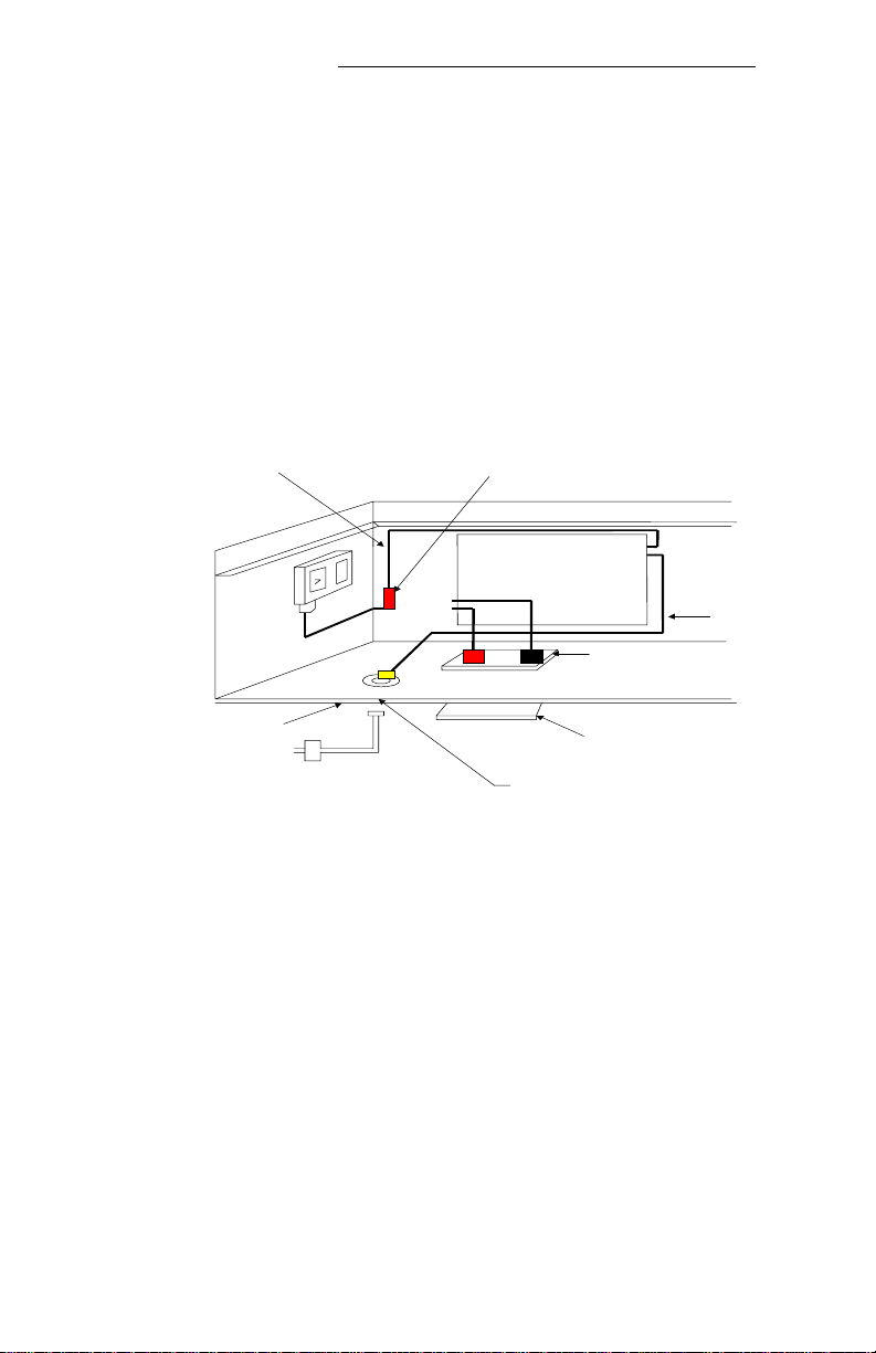
1.0 INST ALLATION
AC OUT-PUT FROM
INVERTER/CHARGER
OUT SIDE FLOOR LINE
CAB POW ER AC INPUT
EXISTIN G 770 C A B P O W ER
BULKHEAD C ONN ECTOR
INVERTER/CHARGER
CAB FLOO R INSIDE FLOOR LINE
Figure A
Basic Installation and Wiring
AC POWER
INPU T TO
THE
INVERTER
TOP FLOOR PASSTHROUGH FLANGE
BOTTOM F LOO R PASSTHROUGH FLANGE
2
1999 Trace Engineering
Page 7

Truck Series 770K Kit
1.0 INST ALLATION
1. Disconnect the positive and negative battery cables at the batteries.
2. Locate a position in or immediately around the positive cable end of the
battery box to mount the fuse-block assembly.
make sure to leave room at both ends to attach the 4/0 battery cables
remove the clear plastic cover from fuse-block assembly and set it aside
place the fuse-block assembly in a desired location
mark mounting hole locations with a pencil or awl
drill four ¼” holes in the battery box and mount the fuse-block assembly
using the included hardware
3. From below the cab, disconnect the external AC input connector.
remove the large nut and washer
4. From inside the cab, lift the AC input harness out of the floor (storage
compartment)
leave the other end connected to the cab power box located on the
driver’s side wall of the same storage compartment
5. Mark the location for the inverter/charger mounting bracket.
mount the bracket in the front-left corner of driver’s side storage
compartment approximately 6” to 8” away from the front wall
note the vertical part of the bracket mounts away from you and faces
toward interior bulkhead wall
once the location is identified, climb under the truck and make sure the
area is clear of:
- structural supports
- wire harnesses
- exhaust system components
using the bracket as a template, drill four ¼” mounting holes through the
floor of the cab
insert four ¼” X 1” bolts through the mounting bracket and floor
and secure using fender washers, lock washers and then nuts
NOTE: Looking down at the top of the pass-through, the positive (red) connection should be on the left and the negative (black) connection on the right.
6. Locate the floor pass-through block adjacent to the mounting bracket (see
diagram). Tight turns with heavy 4/0 cable are required so leave yourself
enough room.
once the location is identified, climb under the truck and make sure area
is clear of:
- structural supports
- wire harnesses
- exhaust system components
remove the pass-through block template from the box and tape it over the
determined mounting location
drill the ¼” pilot holes
drill out the four corner holes with a 5/16” bit
use a 2” hole saw to cut out the remaining three holes
1999 Trace Engineering
3
Page 8

Truck Series 770K Kit
1.0 INST ALLATION
Figure B
Pass-Trough Template
Figure C
Lower Pass-Through Block
Figure D
Pass-Through Block - Lower Assembly
4
1999 Trace Engineering
Page 9

RC8 Remote Control Template
Page 10

RC8 Remote Control Template
Remove this page from the manual
and place it over the mounting location.
5916 - 195th Street N.E., Arlington, WA 98223 Phone: (360) 435-8826 Fax: (360) 435-2229
visit our website at: www.traceengineering.com
Page 11

Floor Pass-through Template
Page 12

Floor Pass-through Template
Remove this page from the manual
and place it over the mounting location.
5916 - 195th Street N.E., Arlington, WA 98223 Phone: (360) 435-8826 Fax: (360) 435-2229
visit our website at: www.traceengineering.com
Page 13

Truck Series 770K Kit
1.0 INST ALLATION
7. Remove the round rubber grommets from the top and bottom flange of the
pass-through block and set them aside for later.
Screw the brass DC studs into the top half of the pass-through block.
Place the top flange into the holes in the cab floor
8. Apply a bead of silicon around the entire outside edge of the bottom passthrough block and around the three internal round holes.
9. Prepare four ¼” X 1” bolts with lock washers. From underneath the truck,
place the bottom flange over the brass studs and bolt it into place.
10. Locate an unpainted location on the frame rail for the chassis ground wire.
cut a length of #10 AWG green wire that is long enough to go from the
location on the frame rail up through the hole in the pass-through block
- be sure to leave several feet of wire inside the cab for later use
crimp a #10 AWG ring terminal on the end of the ground wire and attach
it securely to the unpainted frame rail location
feed the other end through the hole in the pass-through block
11. Take the black plastic battery temperature sensor (with the bright yellow
telephone cord) out of the plastic bag.
remove the backing material to expose the adhesive
clean a spot between two batteries and attach the sensor to one of them
12. Leaving the batteries disconnected, plan the DC battery cable runs:
from the positive battery terminal to one end of the fuse-block
from the other end of the fuse-block to the positive stud on the floor-
pass-through block
from the negative battery terminal to the negative stud on the floor-
pass-through block
battery temperature sensor cable to the opening in the floor-
pass-through block
NOTE: Make sure cable runs are clear of the exhaust system and that you
allow enough slack for movement of the cab.
1999 Trace Engineering
Figure E
Fuse Block Assembly
5
Page 14

Truck Series 770K Kit
1.0 INST ALLATION
Figure F
Fish Tape
RC8
REMOTE CONTROL
Inverter Status
Push
On/Off
Solid Red ------------- Inverting or Charging
Blinking Slow -- -- -- -- -- -- -- Search Mode
Blinking Fast - - - - - - - - - - - - - - - - - - Error
Figure G
RC8 Remote
AC
HOT
IN
Black
Wire
AC
NEU
IN
White
Wire
or Bare
Green
AC
NEU
OUT
White
Wire
AC
HOT
OUT
Black
Wire
Figure H
Inverter Terminal Block
6
1999 Trace Engineering
Page 15

Truck Series 770K Kit
1.0 INST ALLATION
13. Make (or purchase) 4/00 battery cables of the appropriate length. Welding
cable is best as it is the most flexible.
fit the battery cables with flexible plastic conduit over areas where cables
may be subject to chaffing
install the positive and negative battery cables to the correct studs on
the floor-pass-through block using 3/8” fine thread nuts and lock
washers
NOTE: Do not insert a washer between the cable terminal and the brass stud.
install the positive battery cable from the floor pass-through block to one
end of the fuse-block
attach the short positive cable to the other end of the fuse-block using the
included lock washers and nuts
NOTE: Do not connect positive cable to battery at this time.
secure the battery cables and battery temperature sensor cable to the cab
supports and frame rails with nylon tie straps
14. Take one of the round rubber grommets and place the cables in the
appropriate slot:
the small round hole is for the green ground wire
the rectangular slot is for the flat yellow battery temperature sensor cable
the other two holes are unused
15. Remove the RC8 remote control switch from its packaging and locate
the mounting template. The recommended mounting location is as follows:
looking at the sleeper control panel, locate the remote control on the flat
surface immediately to the left of the rotary fan on/off switch
tape the template over the desired mounting location
drill 1/8” mounting holes
drill the ¼” pilot hole for the hole saw
remove the template
cut the 2” opening with the hole saw
feed fish tape up to hole and attach one end of yellow cable. Pull it down
into driver’s side storage compartment
Plug the other end of the yellow cable into the back of the remote control
until it snaps into place.
Place the remote control into mounting hole and screw into place using
the included hardware
16. Connect the RC8 remote control and battery temperature sensor cables by
inserting them into the RJ-11 jacks on the front of the inverter/charger.
Whenproperly seated they will click into place.
17. Locate the chassis ground lug on the back of the inverter/charger.
run the green chassis ground wire to the lug.
cut off any excess wire, strip ½” of green insulation from wire, insert into
the lug and tighten the set screw to secure wire
1999 Trace Engineering
7
Page 16

Truck Series 770K Kit
1.0 INST ALLATION
18. Locate the AC input wiring harness that ships with the kit (it is the harness
with the large hexagon shaped nut at one end).
referencing page 30 of the inverter/charger manual, follow the procedure
for wiring the of AC input to the inverter/charger
using the wire clamp supplied with the kit, secure the AC input power cord
into the left hole (facing the unit)
19. Locate the AC output wiring harness that ships with the kit.
referencing page 30 of the inverter/charger manual, follow the procedure
for wiring the AC output from the inverter/charger
using the wire clamp supplied with the kit, secure the AC outlet cord in
the right hole (facing the unit)
20. Using the supplied hardware install the wiring compartment access cover.
21. Center the holes on inverter/charger mounting flange over the mounting
bracket studs and secure it in place with lock washers and nuts.
22. Make (or purchase) 4/00 DC battery cables to go from the inside studs on
the floor pass-through block to the DC studs on the back of the inverter/
charger.
connect the DC battery cables to correct polarity studs on the back of
the inverter/charger using the supplied lock washers and nuts
cover the connections with the corresponding red and black DC terminal
covers (supplied)
23. Install the new AC input harness into the hexagonal hole in the floor of the
cab (using the large washer and nut from the harness removed earlier in
the installation).
reinstall the external input cord (removed earlier from underneath the
cab)
24. Connect the AC output harness from the inverter/charger to the old
hexagonal connector (removed earlier from the floor).
25. Secure the AC input and output harness wiring to the storage compartment
walls using nylon ties.
26. Connect the battery cables to the batteries according to the following
instructions:
connect the negative battery cable to the negative battery terminal (first)
connect the positive battery cable to the positive battery terminal
reinstall the battery box cover
NOTE: When you connect the positive battery cable to the positive battery
post you can expect a spark. This is caused by the internal capacitors
charging and is completely normal.
The installation in now complete. Refer to the inverter/charger owner’s manual
for complete operating procedures.
8
1999 Trace Engineering
Page 17

Truck Series 770K Kit
2.0 SERVICE INFORMATION
Trace Engineering takes great pride in its products and makes every effort to
ensure your unit fully meets your independent powering needs.
If your product needs repair, contact our Service department at: (360) 435-
8826 to obtain an RMA# and shipping information; or fax this page with the
following information to: (360) 474-0616.
Please provide:
Model Number: _____________________________________
Serial Number: (if applicable) ___________________________
Purchase Date: _____________________________________
Problem: ___________________________________________
Include a telephone number where you can be reached during business
hours and a complete return shipping address (P.O. Box numbers are not
acceptable).
Name:_____________________________________________
Address:___________________________________________
City:_______________________________________________
State / Province:_____________________________________
Zip / Postal Code:____________________________________
Phone: ( )_______________________________________
Country:____________________________________________
visit our website at: www.traceengineering.com
1999 Trace Engineering
or e-mail us at: traceengineering.com
9
Page 18

Truck Series 770K Kit
3.0 WARRANTY
Limited Warranty
Trace Engineering warrants its power products against defects in
materials and workmanship for a period of two (2) years from the date of
purchase and extends this warranty to all purchasers or owners of the product
during the warranty period. Trace does not warrant its products from any and
all defects:
(1) arising out of material or workmanship not provided by Trace
Engineering;
(2) resulting from abnormal use of the product or use in violation of
the instructions;
(3) in products repaired or serviced by other than Trace Engineering
repair facilities;
(4) in components, parts, or products expressly warranted by another
manufacturer.
Trace Engineering agrees to supply all parts and labor, or repair or
replace defects covered by this warranty with parts or products of original or
improved design, at its option, if the defective product is returned to any Trace
Engineering authorized warranty repair facility or to the Trace Engineering
factory in the original packaging, with all transportation costs and full insurance
paid by the purchaser or owner.
All remedies and the measure of damages are limited to the above.
Trace Engineering shall in no event be liable for consequential, incidental,
contingent, or special damages, even if Trace Engineering has been advised
of the possibility of such damages. Any and all other warranties, expressed or
implied, arising by law, course of dealing, course of performance, usage of
trade or otherwise, including, but not limited to, implied warranties of merchantability and fitness for a particular purpose, are limited in duration for a
period of two (2) years from the original date of purchase.
Some countries or states do not allow limitations on the term of an
implied warranty, or the exclusion or limitation of incidental or consequential
damage, which means the limitations and exclusions of this warranty may not
apply to you. Even though this warranty gives you specific legal rights, you
may also have other rights which vary from state to state.
5916 - 195th Street N.E., Arlington, WA 98223 Phone: (360) 435-8826 Fax: (360) 435-2229
10
1999 Trace Engineering
Page 19

Page 20

5916 - 195th Street N.E., Arlington, WA 98223 Phone: (360) 435-8826 Fax: (360) 435-2229
visit our website at: www.traceengineering.com
 Loading...