

Page 1
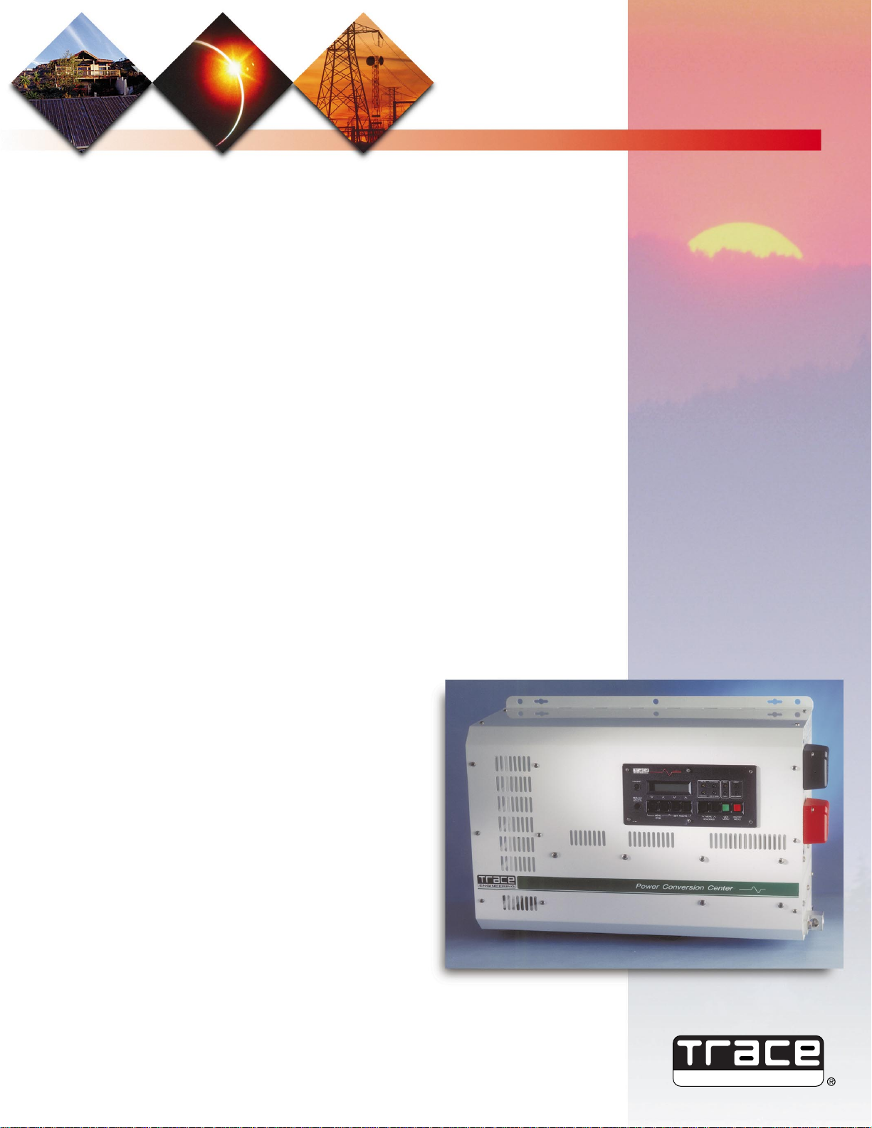
Model SW Series II
A Revolution in Power Technology
The result of new ideas and technologies, the Trace SW Series II delivers sine wave power without
compromise. Now sine wave output with high efficiency, high surge ability and low idle current draw is
available. More than just the finest inverter, with three microprocessors and bi-directional power
topology, it has features and capabilities that previously were non-existent or available only as separate
products.
New Series II Design
• Easier to use programming system with separate “User” and “Setup” menus.
• New backlight LCD display on the control panel improves use in low light conditions.
• Improved AC wiring access and AC conduit provisions makes installation easier.
• New “soft start” systems allows inverter to run even heavier loads and improves reliability.
• Includes a new, easier to read universal owners manual that covers all SW series II inverters.
• Enhanced generator start system works with a greater variety of generator types.
As an Inverter
• Multiple step, low distortion, sine wave output with up to 96% peak conversion efficiency. Very low
idle current draw allows high efficiency even when powering small loads.
• Two inverters can be operated in series to provide 120/240 vac three wire output with twice the power
for 240 VAC loads. Requires optional series interface cable.
• Adjustable search mode can reduce idle power draw to 1 watt when not operating AC loads.
• Adjustable low battery cutout voltage with adjustable time delay prevents damaging batteries.
• Protection circuitry guards against over-current, short circuit, over temperature, low
battery and high battery conditions. Includes islanding protection for utility connected applications.
As a Battery Charger
• High efficiency, low current distortion design enables higher charger output from small generators.
• Three stage, temperature compensated charging algorithm ensures maximum battery life. Remote
battery temperature probe is standard. Includes manual equalize mode with adjustable settings.
• Adjustable grid and generator size allows matching of charger to the AC source.
• Automatic “back-off” system prevents overloading of generators or nuisance tripping of input breakers.
When connected to grid or generator, the SW Inverter synchronizes
its waveform to that of the AC source, locks to it and operates in
parallel. This ability, coupled with the bi-directional power topology
and microprocessor control, makes it possible for the unit to offer
multiple operating modes.
Generator Support Mode:
When charging from a generator,
the generator’s output voltage and current are monitored. If
either falls outside user adjustable limits, the unit sheds itself as
a load and then reverses the power flow if necessary. This
delivers energy from the batteries to the loads assisting the
generator. When operating two units in series at 240 VAC, one
120 VAC leg can be charging while the other is supporting.
Standby Power Mode:
Two AC inputs are provided - one for
generator and one for utility grid. When AC fails, transfer to
inverter power is no longer than 34 milliseconds. If the grid and
generator are connected, the unit can be set to start the generator after the grid has failed. After grid returns, the generator
is automatically stopped. The inverter output is synchronized
to the grid and the grid is reconnected to the loads.
Battery Voltage Transfer Mode:
If the batteries are low, a
low battery set point triggers connection to the grid.
Generator Start Mode:
Automatic generator start features are standard and user programmable.
Gen start can be triggered by either battery voltage or load size connected. A “quiet time”can be set
to restrict generator operation unless absolutely required. The start sequence is fully adjustable and
is now compatible with a greater variety of generator types. Generator must be set up for remote
starting and designed for unattended operation.
ENGINEERING
From
Trace Engineering,
maker of the world’s
most reliable
inverters
An advanced original
and revolutionary
design
Sine wave power
without
compromise
THE POWER COMPANY
POWER CONVERSION CENTER
Page 2
Model
SWSeries II
Nominal DC Input Voltage 12 VDC 12 VDC 24 VDC 24 VDC 48 VDC 48 VDC 48 VDC 48 VDC
AC Output Voltage (RMS) 120 VAC 230 VAC 120 VAC 230 VAC 120 VAC 230 VAC 120 VAC 230 VAC
Nominal Frequency 60 Hz 50 Hz 60 Hz 50 Hz 60 Hz 50 Hz 60 Hz 50 Hz
Continuous Power @ 20° 2500 VA 2600 VA 4000 VA 3300 VA 4000 VA 3300 VA 5500 VA 4500 VA
Continuous AC Output (@ 25°C) 21 amps 11 amps 33 amps 14 amps 33 amps 14 amps 46 amps 20 amps
Maximum AC Output (RMS) 60 amps 28 amps 78 amps 34 amps 78 amps 34 amps 78 amps 34 amps
Efficiency (peak) 90% 90% 94% 94% 95% 95% 96% 96%
Automatic AC Transfer Relay 60 amps 30 amps 60 amps 30 amps 60 amps 30 amps 60 amps 30 amps
Maximum Charging Rate 150 amps 150 amps 120 amps 100 amps 60 amps 50 amps 75 amps 60 amps
DC Input Requirements
Search Mode 0.08A (1W) 0.08A (1W) 0.04A (1W) 0.04A (1W) 0.025A(1W) 0.025A(1W) 0.04A (1W) 0.04A (1W)
On Mode (no load - idle) 1.0A (12W) 1.6A (12W) 0.66A (16W) 0.66A (16W) 0.33A (16W) 0.33A (16W) 0.40A (20W) 0.40A (20W)
At Full Rated Power 275 amps 150amps 200 amps 166 amps 100 amps 83 amps 137 amps 106 amps
Short Circuited Output 700 amps 300 amps 360 amps 320 amps 180 amps 160 amps 180 amps 138 amps
Nominal DC Input Voltage Range 11.8 to 16.5 11.8 to 16.5 22 to 33 22 to 33 44 to 66 44 to 66 44 to 66 44 to 66
AC Output Characteristics
AC Output Waveform Sinewave, 34 to 52 steps per cycle
Voltage Regulation +/- 2%
Total Harmonic Distortion 3 to 5% (stand alone operation)
Power Factor Allowed -1 to 1
Frequency Regulation +/- 0.04% (crystal regulated)
Load Sensing Range 16 to 240 Watts
Options
Remote Control Panel (50 ft. max.) SWRC SWRC SWRC SWRC SWRC SWRC SWRC SWRC
Stacking Interface for double power SWI* No SWI* No SWI* No SWI* No
(*requires two inverters) (120/240) (120/240) (120/240) (120/240)
Conduit Box SWCB SWCB SWCB SWCB SWCB SWCB SWCB SWCB
DC Disconnect Breaker DC 250 DC 250 DC 250 DC 250 DC 175 DC 175 DC 250 DC 175
DC Battery / Inverter Cables BC5-4/0 BC5-4/0 BC5-4/0 BC5-4/0 BC5-2/0 BC5-2/0 BC5-4/0 BC5-2/0
Enclosure Type Indoor, ventilated, steel chassis with powdercoat finish
Specified Temp Range 32° F to 104° F (0° C to +40° C) (output will meet specified tolerances)
Allowed Temp Range -40° F to 140° F (-40° C to +60° C) (output may not meet specified tolerances)
Dimensions - Inverter Only 15" (38 cm) high, 22.5" (57 cm) wide, 9" (23 cm) deep (when wall mounted)
Dimensions - Shipping 20.5" (52 cm), 27" (69 cm), 15.5" (40 cm)
Mounting Wall or Shelf Mount
Weight - Inverter Only 90lbs (42kg) 95lbs (43kg) 105lbs (48kg) 105lbs (48kg) 105lbs (48kg) 105lbs (48kg) 136lbs (63kg) 136lbs (63kg)
Weight - Shipping 96lbs (44kg) 110lbs (50kg) 111lbs (50kg) 111lbs (50kg) 111lbs (50kg) 111lbs (50kg) 143lbs (65kg) 143lbs (65kg)
SPECIFICATIONS
ENGINEERING
THE POWER COMPANY
Available From:
Utility Interactive Mode:
Operating as a bi-directional battery charger, power from any source that tries to
raise the batteries above their programmed float voltage is delivered to the grid. A GRID USAGE TIMER can be
set to allow selling of electricity to the utility only during prescribed hours. Sell back current is adjustable.
Caution: Utility intertie must have approval of local utility company.
Peak Load Shaving Modes
- (1) The sine wave series may be programmed to operate from batteries during a
specified period of the day. Batteries may be charged during lower rate periods. (2) During a programmable
time of the day, power is delivered to the grid from the batteries. An alternative (lower) adjustable float voltage
is employed to allow variable battery discharge depths.
Three user adjustable voltage-controlled signal relays are provided to control charging sources and loads.
Selecting modes, enabling features and adjusting parameters are easily accomplished by moving thru a menu tree
that is displayed on the control panel’s LCD read-out. Doubling as a meter, the LCD displays INVERTER AMPS,
INPUT AMPS, LOAD AMPS, BATTERY VOLTS DC and INVERTER VOLTS AC. Additionally, control panel LED’s report
the status of eight system conditions.
Specifications SW2512 SW2612E SW4024 SW3024E SW4048 SW3048E SW5548 SW4548E
*specifications may change without notice
Options: Remote control panel (SWRC), stacking interface cable (SWI), conduit box for code approved DC input battery cables (SWCB).
Other Voltage/frequency for export are as follows:
SW3024J=105VAC/50Hz SW4024K=105VAC/60Hz SW4024W=220VAC/60Hz (two wire output only) SW4548A-240VAC/50Hz
®
L
I
S
T
E
D
C
67664
®
L
I
S
T
E
D
67664
POWER CONDITIONING UNITS FOR
USE IN PHOTOVOLTAIC POWER
SYSTEMS STANDARD UL1741
POWER CONVERTERS AND POWER
CONVERTER SYSTEMS FOR
RECREATIONAL VEHICLES
STANDARD UL458
COMMERCIAL AND INDUSTRIAL
POWER SUPPLIES
CERTIFIED TO
CAN/CSA-C22.2 NO. 107.1-M1
ETL TESTING LABS. INC
CORTLAND, N.Y.
Rev# 11/97
5916 195th St. N.E. ARLINGTON, WA. USA 98223 Phone (360) 435-8826 Fax (360) 435-2229 Web: www.traceengineering.com
5400
5200
5000
4800
4600
4400
4200
4000
3800
3600
3400
3200
3000
2800
2600
2400
2200
2000
1800
1600
1400
1200
1000
800
600
400
200
0
120%
100%
80%
60%
40%
20%
0%
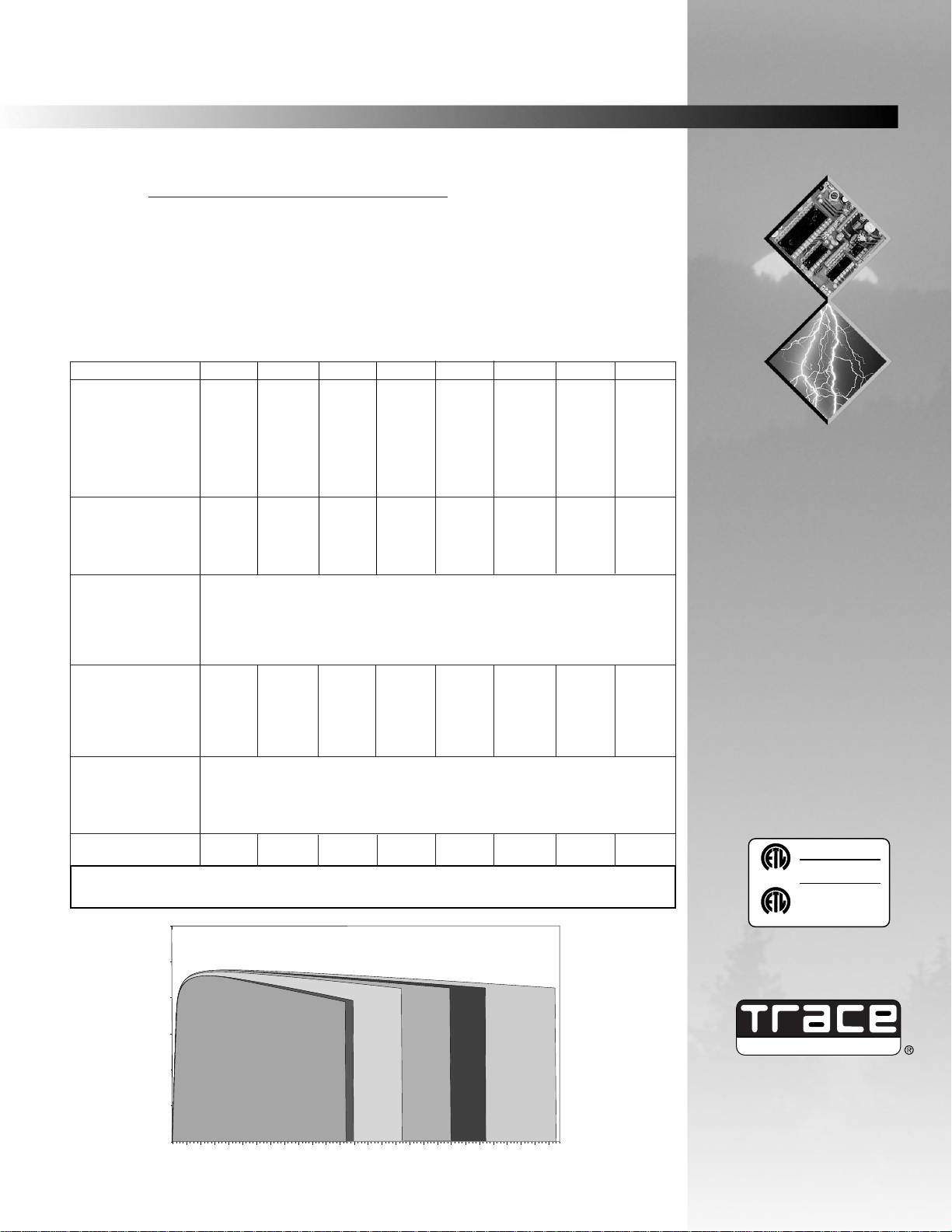
SW5548
SW458E
SW2612E
SW2512
SW4024 / SW4048
SW3024E / SW3048E
AC Load Watts
Efficiency
SW Series Efficiency Curves
 Loading...