

Trace Engineering PM DR 250 S, PM DR 175, PM DR 175 Dual, PM DR 250 Dual, PM SW 175 S Assembly Instructions Manual
...Page 1
Power Module System
Assembly Instructions
How To Use This Manual (inside cover)
Inverter Systems ...Chapter Four
Electrical Components … Chapter Five
Cabinet Components … Chapter Six
5916 195th Street NE, Arlington WA USA 98223 (360) 435-8826
Part Number 3471
Page 2

How to Use this Manual
Go to Chapter Four and select the assembly instructions for the
desired system.
Single DR system .... Page 4-4
Dual DR system … Page 4-8
Single SW system .... Page 4-10
Dual SW system .... Page 4-12
Three-phase SW system .... Page 4-14
Go to Chapter Five and select the assembly instructions for each
electrical component listed in the system.
Go to Chapter Six and select the assembly instructions for each
cabinet component listed on the system assembly instructions.
Gather all cabinet and electrical components and tools listed on
the system assembly instructions.
Arrange all instruction sheets in the order suggested on the
system assembly instructions.
Assembly your system.
Page 3

Table of Contents
Introducing the Power Module System .....1-1
IMPORTANT SAFETY INSTRUCTIONS .....2-1
General Precautions ............................2-1
Personal Precautions ............................2-2
Underwriters Laboratory (U.L.) Compliance Requirements.........2-3
Power Module Installation ...........3-1
Powering Up the System ..........................3-1
Stacked Pair Inverters ...........................3-2
Power Module Systems .............4-1
Power Module Fastener Facts .......................4-2
PM DR 175/250 Single Inverter Diagram ..................4-4
PM DR 175/250 Dual Diagram .......................4-8
PM SW 175/250 S Diagram ........................4-10
PM SW 175/250 Dual Diagram ......................4-12
Sinewave 3 - Phase System........................4-16
3-Phase Assembly Sequence .......................4-17
Electrical Components Assembly Instructions 5-1
PMO-AC15/20/60 Front View ........................5-3
PMO-AC60 3-Phase Breaker ........................5-5
PMO-C40, C40K & VLC40 for DR Systems ................5-7
PMO-C40, C40K & VLC40 for DR Systems ................5-8
PMO-40, C40k & VLC40 for Sinewave Systems ..............5-9
PMO-DC20/60/110 ............................5-11
PMO-DC20/60/110 ............................5-12
PMO-DC175/250 .............................5-13
PMO-DC175/250 .............................5-14
PMO-DCBB/Kit/SW/DR ..........................5-15
PMO-DCBB/Kit/(SW)(DR) .........................5-16
PMO-DCBB ................................5-17
PMO-IOX60 Input/Output/Bypass Breaker ................5-19
Page 4

PMO-IOX60 ................................5-20
PMO-NEUTRAL ..............................5-21
Cabinet Components ...............6-1
PM .....................................6-3
PMADD...................................6-5
PM-EXT ...................................6-7
PMO-BLANK ................................6-9
PMO-BRACE ...............................6-11
PMO-COVER ...............................6-13
PM-DOOR .................................6-15
PM-FEET .................................6-17
PM-LID ..................................6-19
PM-LATCHES & LOCKS .........................6-21
PMO-SLIDER ...............................6-23
PMO-TRAY ................................6-25
Limited Warranty .................7-1
Life Support Policy ................7-2
Page 5

1-1
Introducing the Power Module System
The Trace Modular Power System incorporates all the components of an alternative energy installation (except
external AC and DC power sources) in a package designed to permit seamless integration of the components.
The modular approach enables you to order individual components or complete systems fully assembled, tested,
and inspected.
The Power Module System allows isolation of components, wiring, and safety circuitry in a secure cabinet that
can be weatherproofed for exterior installations. Cabinets can be stacked up to four high for integration of
batteries, inverters, controllers, circuit breakers, and associated devices. Each module can house individual or
multiple components.
The base configuration is supplied as individual components or in complete assemblies (inverters are shipped
separately) from the factory. Assembled systems can include as many or as few components as desired. For
example: use one standalone module to house vented liquid lead-acid batteries, and another to house electronic
components; or stack multiple modules to house sealed batteries and all other components in one
installation.System components provided with the modules can include AC and DC breakers, disconnects,
inverters, controllers, busses, DC shunt and bonding blocks, grounding blocks, wiring, and fasteners for field
installation. These components (and batteries) can also be shipped or acquired separately.
When ordering parts, always use the PMO- prefix.
Other Power Module System features include:
• Powder-coated aluminum enclosures
• Stainless steel mounting hardware
• Removable front-panel for easy access
• Louvered front-panel for maximum ventilation
• Single or multiple Sinewave or DR Series inverters w/hardware
• Accessories include:
ü
cabinet weather proofing kit (PMO-ODTEK)
ü
bolt-down bottom mounting brackets (PMO-FEET)
ü
access panel locks w/keys (PMO-LOCKS)
ü
module extender for extra-high batteries (PMO-EXT)
ü
durable battery tray for isolating batteries from base (PMO-TRAY)
ü
C40 multipurpose controller (PMO-C40)
ü
voltage-limiting C40 multipurpose controller (PMO-VLC40)
ü
C40 installation kit (PMO-C40K)
ü
ground-fault disconnect (PMO-GFP)
ü
add-on module for additional battery capacity (PMO-ADD)
ü
20 to 60 amp Heineman™ DC breakers
ü
15 to 60 amp Square D™ AC breakers
ü
DC negative bonding block with shunt (PMO–DCBB)
ü
modular power distribution block (PMO-PDBB)
ü
utility/generator neutral bonding block (PMO-NEUTRAL)
ü
lockable acrylic breaker covers (PMO-COVER)
ü
sliding breaker fill-plates (PMO-SLIDER)
Copyright Trace Engineering Co., Inc. Telephone (360) 435-8826 Part Number 3471
5916 195th Street, NE Fax (360) 435-2229 Released: Thursday, April 29, 1999
Arlington, WA 98223 USA www.traceengineering.com
Page 6

1-2
This page intentionally left blank.
Copyright Trace Engineering Co., Inc. Telephone (360) 435-8826 Part Number 3471
5916 195th Street, NE Fax (360) 435-2229 Released: Thursday, April 29, 1999
Arlington, WA 98223 USA www.traceengineering.com
Page 7

General Precautions 2-1
IMPORTANT SAFETY INSTRUCTIONS
SAVE THESE INSTRUCTIONS !
This manual contains important safety and operating instructions. This manual also covers assembly of the
Trace Engineering line of Power Modules with both Sinewave and DR series inverters, C40 charge controllers,
AC and DC disconnects, PVGFP, and other devices. Specific operating and hookup instructions for each
separate component are provided in the individual component manuals packaged with these assembly
instructions. Before installation, review the applicable sections of this manual, and always follow the safety
practices described below:
General Precautions
1. Before using the inverter/charger, read all instructions and cautionary markings on (1) the
inverter/charger, (2) the batteries and (3) charge controllers, and (4) in this manual as well as the individual
manuals provided for each component of the system.
2. CAUTION - To reduce risk of injury, charge only deep-cycle lead acid, lead antimony, lead calcium, gel
cell, absorbed mat, or NiCad/NiFe type rechargeable batteries. Other types of batteries may burst, causing
personal injury and damage.
3. Do not expose the Power Module to rain, snow, or liquids of any type without proper installation of the
sealing kit, which is included with each Power Module
4. Qualified personnel (with electrical experience) should make all electrical connections. Incorrect
installation may result in a risk of electric shock or fire.
5. To reduce risk of electric shock, disconnect all wiring before attempting any maintenance or cleaning.
Turning off the inverter will not reduce this risk; the inverter by-pass breaker must be used and the power
module must be totally disconnected from all sources. Solar photovoltaic modules produce current when
exposed to light - cover them with opaque material before servicing any connected equipment.
6. If using a power module as a battery enclosure, support the additional weight the module must carry as
described in the PMO-FEET section. The mounting feet are required as well as a concrete pad or timbers
to support the bottom tray of each cabinet stack as shown in the section on PMO-FEET (page 6-17).
7. WARNING - WORKING IN THE VICINITY OF A LEAD ACID BATTERY IS DANGEROUS. BATTERIES
GENERATE EXPLOSIVE GASES DURING NORMAL OPERATION. Provide ventilation to the outdoors
from the battery compartment. The battery enclosure should be designed to prevent accumulation and
concentration of hydrogen gas in “pockets” at the top of the compartment. Vent the battery compartment
from the highest point.
8. NEVER charge a frozen battery.
9. No terminals or lugs are required for hook-up of the AC wiring. AC wiring must be no less than 10 AWG
(2.6mm) gauge copper wire and rated for 75C or higher. Battery cables must be rated for 75C or higher and
should be no less than #4/0 AWG (11.7 mm) for PM-XX250/X systems and #2/0 AWG (9.3 mm) gauge for
PM-XX175/X systems. Crimped and sealed copper ring terminal lugs with a 5/16 hole should be used to
connect the battery cables to the negative DC shunt terminals of the Power Module (lug not needed for the
positive terminal). Soldered cable lugs are also acceptable.
Copyright Trace Engineering Co., Inc. Telephone (360) 435-8826 Part Number 3471
5916 195th Street, NE Fax (360) 435-2229 Released: Thursday, April 29, 1999
Arlington, WA 98223 USA www.traceengineering.com
Page 8
2-2 Personal Precautions
10. Torque all AC wiring connections to 20 inch-pounds. Torque all DC cable connections 10-12 footpounds. Be extra cautious to reduce the risk of dropping a metal tool onto batteries. It could short- circuit
the batteries or other electrical parts resulting in sparks that could cause an explosion.
11. Tools required to make AC wiring connections: Wire strippers, ½" (13MM) open-end wrench or socket,
Phillips screw driver #2, 3/16” ( 5mm) & 1/4" (6MM) slotted-screw driver, and a torque wrench.
12. The Power Module is intended to be used with a battery supply with a nominal voltage equal to the last
two digits in the inverter/charger’s model number. For example: a SW4024 is a 24 volt inverter, a DR1512 is
a 12 volt inverter. (The first two digits are Power output in hundreds of watts)
13. Instructions for mounting: See mounting instruction section of this manual. For battery
installation and maintenance: read the battery manufacturer’s installation and maintenance
instructions prior to operating.
14. DC GROUNDING INSTRUCTIONS - This Power Module should be connected to a grounded,
permanent wiring system. For most installations, the negative battery conductor should be bonded to the
grounding system at one (and only one point) in the system. All installations should comply with all national
and local codes and ordinances.
15. Fully assemble each module from the bottom up before adding the next module, up to a maximum stack
height of four modules. This includes attaching and tightening all mounting hardware. The strength and
stability of the modular system is dependent on all fasteners being connected and tightened properly.
Personal Precautions
1. Someone should be within range of your voice to come to your aid when you work near batteries.
2. Have plenty of fresh water and soap nearby in case battery acid contacts skin, clothing, or eyes.
3. Wear complete eye protection and clothing protection. Avoid touching eyes while working near batteries.
Wash your hands when done.
4. If battery acid contacts skin or clothing, wash immediately with soap and water. If acid
enters eye, immediately flood eye with running cool water for at least 15 minutes and get
medical attention immediately.
5. Baking soda neutralizes lead acid battery electrolyte. Keep a supply on hand in the area of the batteries.
6. NEVER smoke or allow a spark or flame in vicinity of a battery or generator.
7. Be extra cautious to reduce the risk of dropping a metal tool onto batteries. It could short-circuit the
batteries or other electrical parts which may result in a spark which could cause an explosion.
8. Remove personal metal items such as rings, bracelets, necklaces, and watches when working with a
battery. A battery can produce a short-circuit current high enough to weld a ring or the like to metal, causing
severe burns.
9. This is a negative grounded system. Always connect the positive or hot wires before connecting the
negative or neutral wires when installing all equipment. This will reduce the chance of shorting the wires to
the cabinet or equipment when routing wires. This is particularly important when routing the battery cables.
10. As an additional precaution, the ends of the battery cables should be taped when routing
through cabinet openings and conduit.
Copyright Trace Engineering Co., Inc. Telephone (360) 435-8826 Part Number 3471
5916 195th Street, NE Fax (360) 435-2229 Released: Thursday, April 29, 1999
Arlington, WA 98223 USA www.traceengineering.com
Page 9

Underwriters Laboratory (U.L.) Compliance Requirements 2-3
11. If a remote or automatic generator start system is used, disable the automatic starting circuit and/or
disconnect the generator from its starting battery while servicing to prevent accidental starting.
Underwriters Laboratory (U.L.) Compliance Requirements
The Power Module cabinet is listed (UL file#39FL under “Rainproof Modular Enclosure for use as a
photovoltaic Power System Accessory,” UL1741. The modules are shipped with a listing sticker approved
for use by UL. The sticker is valid if and only if the following compliance requirements are met in the final
installation.
1. Stability Requirements The optional mounting feet (PMO-FEET) must be included for each
assembled cabinet. The bottom module of each cabinet must be secured with at least six 1/2" anchor
bolts through the mounting feet to a concrete pad or platform of sufficient mass and footprint to keep the
completed cabinet and the intended contents from being pushed over. It is the user’s responsibility to:
insure that the concrete pad or platform meet these requirements;
ü
maintain the anchor bolts over time;
ü
replace components as needed.
ü
Additional mounting of the upper module(s) to a wall may be needed to meet local earthquake code
requirements.
2. Grounding Continuity Requirements Individual modules, doors, and lids must be assembled as per
the details outlined in this manual with the fastening hardware supplied by Trace Engineering. The PM
modules and lid must have a star washer on the outside between the head of the carriage bolt and the
module, and on the inside between the module and the nut, to insure grounding continuity between
modules. The door latch assemblies are factory installed with earth nuts and the powder-coat is removed
on the module where the door latch contacts to insure grounding continuity of the doors. As an added
insurance, the neoprene gasket is attached to the module between the door to insure that the latch
remains in contact with the bare metal spot. It is the user’s responsibility to insure that the gasket remains
maintained over time and replace as needed.
3. Baffle Requirements The water baffle and screening is required on each door on a module containing
electronic components for all installations. The kit (PMO-ODTEK) is factory installed as per the
instructions outlined in this manual. After assembly, use the silicone rubber sealant included with the kit to
treat all seams to insure lone-term weather-proofing perfoamance. It is the user’s responsibility to
maintain the weatherproofing accessories over time, and to replace components as needed.
4. The installer/user is responsible to insure that the power module cabinets are properly installed and that
all electrical connections are made to meet local National Electric Code (NEC) and inspector’s
requirements.
Copyright Trace Engineering Co., Inc. Telephone (360) 435-8826 Part Number 3471
5916 195th Street, NE Fax (360) 435-2229 Released: Thursday, April 29, 1999
Arlington, WA 98223 USA www.traceengineering.com
Page 10

2-4 Underwriters Laboratory (U.L.) Compliance Requirements
This page intentionally left blank.
Copyright Trace Engineering Co., Inc. Telephone (360) 435-8826 Part Number 3471
5916 195th Street, NE Fax (360) 435-2229 Released: Thursday, April 29, 1999
Arlington, WA 98223 USA www.traceengineering.com
Page 11

Powering Up the System 3-1
Power Module Installation
Read all precautions at the beginning of this manual and the individual component manuals before
attempting to install the system. Because of tool clearances needed to make connections, It is easiest to
make all external connections to the PM (charge controllers, PV array, and AC inputs/outputs, before
installing the inverter. As a general rule, connections should be made along the back panel, than the side
panels, and lastly to equipment mounted on the tray.
Install the inverter to the module tray using all six stainless steel bolts, washers and nuts supplied. Insure
that the DC and AC sides of the inverter correspond with the DC and AC breaker locations in the Power
Module. When all six fasteners are secured there is no need for additional bracing of the module tray, since
the inverter chassis will add stiffness. Torque to 79 inch-pounds.
Connect the battery positive cable from the battery disconnect and the battery positive cables from all
charge controllers to the inverter DC positive lug. Torque nut to 12 ft-lbs and place a protective cover over
the terminal.
Connect the battery negative cable from the inverter, and the battery negative cables from all charge
controllers to the inverter DC negative bonding block (DCBB page ). Torque nut to 12 ft-lbs and place
protective cover over the terminal.
Make AC connections from the AC input/output/bypass inverter breaker to the inverter. All wires are marked
identical to the labels at the connectors inside the inverter. AC Utility In should be connected into AC1 and,
if a generator is used as an additional AC input it should be connected to AC2, (it will normally have an
additional AC input/output/bypass breaker).
Grounding Parameters: Connect D.C. Ground wire (8 AWG) to grounding rod. Connect the A.C. Ground at
the main AC panel ground connection if used in a residential or commercial application. NEC and local
codes determine the complete grounding requirements.
Powering Up the System
Before applying power to the Power Module for the first time, take time to check and confirm the following
key items:
1. Check to see that the AC loads and AC source are connected properly into the inverter bypass box.
2. Confirm that the battery cable polarities are proper. Connection with improper polarity is an expensive
mistake, very obvious and not covered under warranty.
3. Check the PV array connections at the array and at the Power Module. Be sure the PV array positive is
connected to the bottom of the PV array disconnect as illustrated.
4. Confirm that all connections are tight and wire size is appropriate as described above and shown on the
installation diagram. Once these checks have been completed, it is time to apply power to the system. Do so
as follows:
A. Turn the battery DC disconnect(s) to the on (up) position.
B. Turn the solar array disconnect(s) to the on (up) position.
C. Turn the inverter(s) on as outlined in the individual component manual, and check for proper
operation. If the inverter does not power up, go to step F.
D. Unlock the main AC breaker that will feed the inverter and activate the AC source used to provide
power to the system (generator or main breaker).
Copyright Trace Engineering Co., Inc. Telephone (360) 435-8826 Part Number 3471
5916 195th Street, NE Fax (360) 435-2229 Released: Thursday, April 29, 1999
Arlington, WA 98223 USA www.traceengineering.com
Page 12

3-2 Stacked Pair Inverters
E. Turn the inverter bypass breaker to the position noted in the residence wiring diagram on the
bypass box that will turn the inverter system on. The Power Module system is now fully connected
and operable. Should any problems arise that are not covered in this installation manual, contact
Trace Engineering or your dealer. Note: Perform the next step only if the inverter fails to Power up
when turned on.
F. Using a multi meter, check for appropriate battery voltage at the inverter DC terminals. (This will
require removing the end cover from the inverter.) If the battery voltage is appropriate confirm proper
battery cable polarity and connection, and make sure the batteries are not completely discharged. If
the inverter still doesn’t work contact your dealer or Trace Engineering.
Stacked Pair Inverters
If your P M includes a stacked pair of inverters the physical connection of the PM is no different. However,
since 240 volts AC is available across the two inverter’s AC outputs, connection of the AC loads to the
system via the bypass breaker is a little different. Refer to the section on stacking inverters in the individual
inverters owner’s manual included with the system.
Connect the AC loads that will run from 120 volts AC, to the AC output of the individual inverters at the
bypass breaker box. It is best to try and balance the AC loads between the two inverters if possible. The
load(s) that is to run from 240 volt AC output should be connected across the two inverters outputs by
connecting the neutral wire (white) to the neutral block in the bypass box, and one hot wire to each of the
inverter bypass box AC load points
Copyright Trace Engineering Co., Inc. Telephone (360) 435-8826 Part Number 3471
5916 195th Street, NE Fax (360) 435-2229 Released: Thursday, April 29, 1999
Arlington, WA 98223 USA www.traceengineering.com
Page 13

4-1
Power Module Systems
PM Systems
Single DR Inverter Diagram ............3
Dual DR Inverter Diagram .............5
PM SW 175/250 S Diagram.............7
Dual Sinewave Inverter Diagram .........9
Sinewave 3 - Phase System ...........11
Copyright Trace Engineering Co., Inc. Telephone (360) 435-8826 Part Number 3471
5916 195th Street, NE Fax (360) 435-2229 Released: Thursday, April 29, 1999
Arlington, WA 98223 USA www.traceengineering.com
Page 14
4-2 Power Module Fastener Facts
Power Module Fastener Facts
Table 1, Fastener Description and Application
Where Used Trace PN Description Quantity
Inverter to PM 425 1/4-20 x 3/4" SS bolt 6
468 1/4" SS flat washer 12
2147 1/4" SS external star washer 12
444 1/4-20 SS hex nut 6
PM-FEET 3191 #10-24 x 1" SS carriage bolt 14
485 1/4" SS internal star washer 14
442 #10-24 SS hex nut 14
465 #10 SS flat washer 14
PMO-ADD 3190 #10-24 x 1/2" SS carriage bolt 14
485 1/4" SS internal star washer 14
2147 1/4" SS external star washer 14
465 #10 SS flat washer 14
442 #10-24 SS hex nut 14
PM-LID 3191 #10-24 x 1" SS carriage bolt 6
485 1/4" SS internal star washer 6
2147 1/4" SS external star washer 6
465 #10 SS flat washer 6
3329 #10-24 SS wingnut 6
Table 2, Fastener Torque Values
Trace PN Description Torque value
3190 #10-24 x 1/2" SS carriage bolt 25 in-lbs
3191 #10-24 x 1" SS carriage bolt 25 in-lbs
465 #10 SS flat washer N/A
442 #10-24 SS hex nut 25 in-lbs
3329 #10-24 SS wingnut Finger tight
425 1/4-20 x 3/4" SS cap screw 80 in-lbs
468 1/4" SS flat washer N/A
485 1/4" SS internal star washer N/A
2147 1/4" SS external star washer N/A
444 1/4-20 SS hex nut 80 in-lbs
Copyright Trace Engineering Co., Inc. Telephone (360) 435-8826 Part Number 3471
5916 195th Street, NE Fax (360) 435-2229 Released: Thursday, April 29, 1999
Arlington, WA 98223 USA www.traceengineering.com
Page 15

4-3
Single DR System
Copyright Trace Engineering Co., Inc. Telephone (360) 435-8826 Part Number 3471
5916 195th Street, NE Fax (360) 435-2229 Released: Thursday, April 29, 1999
Arlington, WA 98223 USA www.traceengineering.com
Page 16
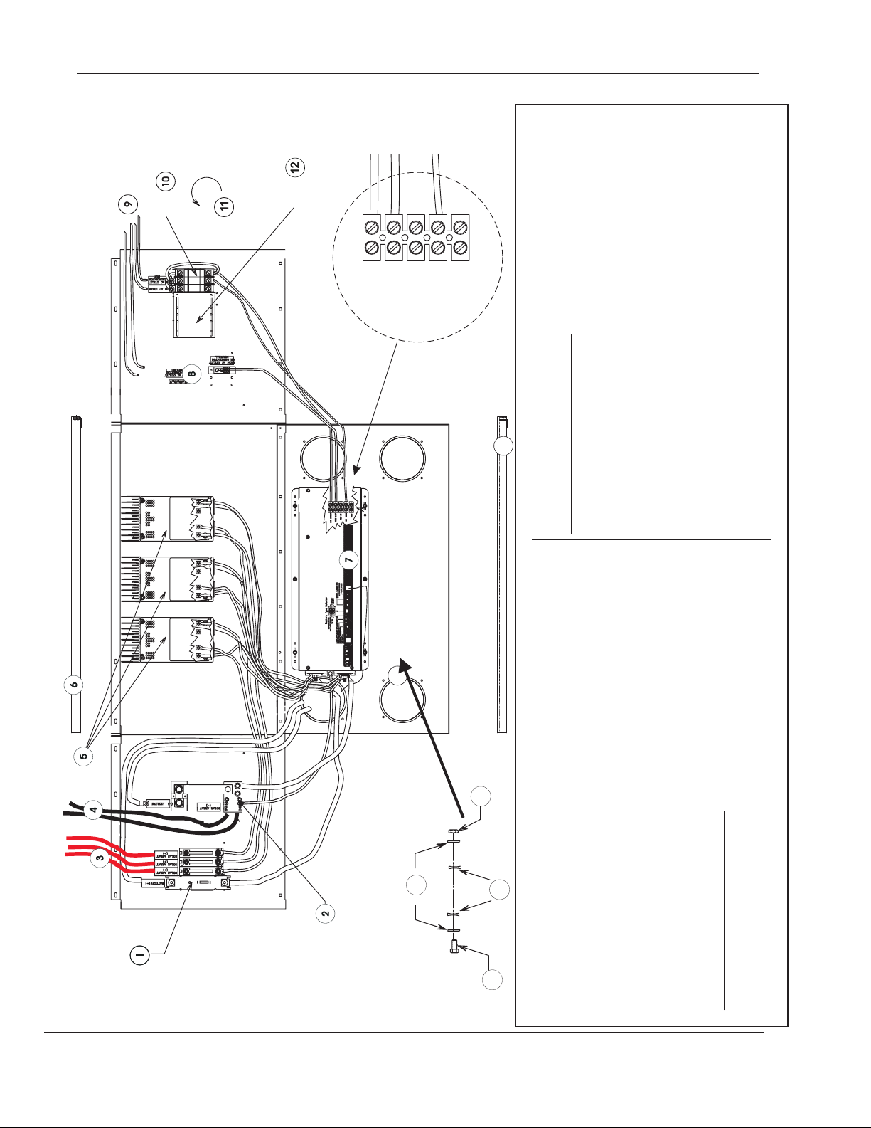
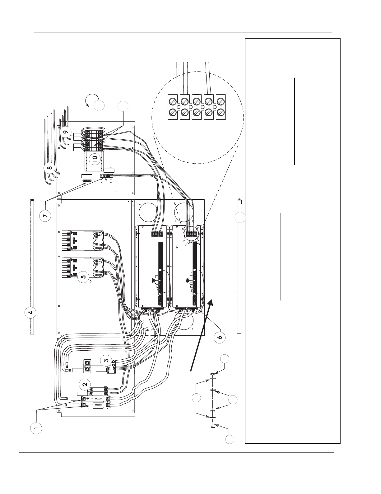
4-4 PM DR 175/250 Single Inverter Diagram
Hot In
Hot Out
Neutral Out
Neutral In
Ground
13
14
3 US PV wiring (not included)3
#Qty Part No. Description
4 AR US DC ground cabling; one to PV array ground, other to earth ground rod
5 AR optional C40’s (not included) up to three.
6 1 LID enclosure top
7 1 US DR Inverter not included
8 1 AC Neutral AC neutral bonding block, with AC ground bonding block
9 AR US AC wiring (not included)
10 1 IOX60 AC input/output/bypass lockout disconnect
11 2 COVER, PMO- weather-tight, locking switch cover
12 2 SLIDER, PMO- unused breaker opening cover
13 1 FEET, PMO- brackets to secure the power module to the base or pad
14 4 Edge guard Cut to length and install around cable passages in the base to prevent
chaffing.
These fasteners are used for attaching the inverter to the floor of the cabinet:
A 6 425 ¼ - 20 X ¾” HH SS bolt
B 12 2147 ¼” external tooth starwasher
C 12 468 ¼” flat washer
PM DR 175/250 Single
D
B
C
A
All configurations use 6 AWG THHN wire for AC and PV wiring. Inverter cables are 4/0
for DR2412 and 3624. DR1512, 1524, and 2424 inverters use 2/0 cable. User red heat
shrink for positive and black heat shrink for negative. Refer to the DR Owner’s Manual for
cable sizing. Each assembly also includes the door (not shown). Refer to the individual
components assembly descriptions. Follow the assembly sequence as shown on the
reverse side of this page. When ordering parts for your system, always prefix the desired
part number with the letters PMO-. AR means As Required; US means User Supplied.
Qty Part No. Description
#
I nverter Diagram
Copyright Trace Engineering Co., Inc. Telephone (360) 435-8826 Part Number 3471
5916 195th Street, NE Fax (360) 435-2229 Released: Thursday, April 29, 1999
Arlington, WA 98223 USA www.traceengineering.com
1 1 DC175 175 amp DC circuit breaker used with DR1512, 1524, OR 2424
DC250 250 amp DC circuit breaker used with DR2412 or3624
2 1 DCBB DC bonding block with shunt
Page 17

PM DR 175/250 Single Inverter Diagram 4-5
PM DR 175/250 S Assembly Sequence
1. Feet (Page 6-17)
2. Edge guards
3. C40 if equipped (Page 5-7)
4. Neutral and ground bonding block (left panel for SW, right panel for DR, Page 5-21)
5. DC bonding block (left for DR, right for SW, Page 5-15)
6. DC shunt
7. DC bus bars
8. DC175/250 (Page 13)
9. DC20/60/110 (Page 12)
10. IOX60 (Page 19)
11. any additional AC or DC breakers
12. Slider (Page 23)
13. Cover (Page 13)
14. connect ground conductors
15. AC output cables
16. AC neutral cables
17. DC cables
18. Decals
19. Lid (Page 19)
20. Door (Page 15)
Assembly Instructions: Invert PM and install feet; turn PM upright to continue. Remove appropriate
component instruction sheets and arrange in order of installation. Gather all tools and components
listed in the instructions and place them nearby. Prepare components as instructed on the
component assembly pages and set aside. When all cables, components, fasteners, etc. are
prepared and handy, assemble each component in the sequence as shown, referring to the
component assembly instructions as required.
When ordering parts, always use the PMO- prefix.
Copyright Trace Engineering Co., Inc. Telephone (360) 435-8826 Part Number 3471
5916 195th Street, NE Fax (360) 435-2229 Released: Thursday, April 29, 1999
Arlington, WA 98223 USA www.traceengineering.com
Page 18

4-6 PM DR 175/250 Single Inverter Diagram
This page intentionally left blank.
Copyright Trace Engineering Co., Inc. Telephone (360) 435-8826 Part Number 3471
5916 195th Street, NE Fax (360) 435-2229 Released: Thursday, April 29, 1999
Arlington, WA 98223 USA www.traceengineering.com
Page 19

PM DR 175/250 Single Inverter Diagram 4-7
Dual DR System
Copyright Trace Engineering Co., Inc. Telephone (360) 435-8826 Part Number 3471
5916 195th Street, NE Fax (360) 435-2229 Released: Thursday, April 29, 1999
Arlington, WA 98223 USA www.traceengineering.com
Page 20
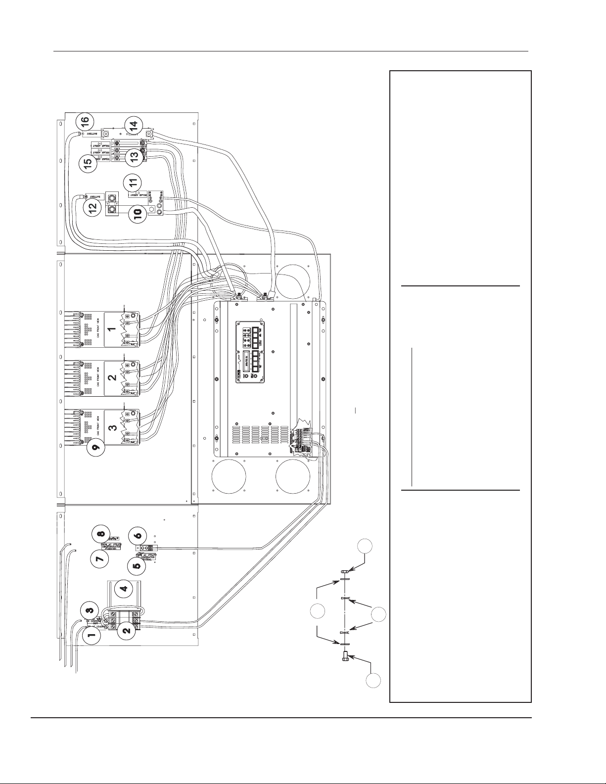
4-8 PM DR 175/250 Dual Diagram
11
HOT
RGENERAT
OMAC UTIL
ACLOADS
HOT
RGENERAT
OMAC UTIL
ACLOADS
12
Hot Out
Neutral In
Hot In
Ground
to the floor or base
disconnect circuit breaker
Neutral Out
8 AR US AC 6 AWG THHN
9 AR US AC wiring 6AWG THHN
NEUTRAL
ORGENERATOR
GROUND
ORGENERATOR
FROMAC UTILITY
FROMAC UTILITY
10 1 PMO-SLIDER covers unused breaker slots
#Qty Part No. Description
11 2 PMO-COVER flip-up cover for breakers
12 2 PMO-IOX60 input, output, bypass,
13 1 PMO-FEET brackets to secure the module
13
PV(-) Battery(-)
Battery(+) PV(+)
PV(-) Battery(-)
Battery(+) PV(+)
DR Series Inverter #1
GND
HOTIN
NEUIN
HOTOUT
NEUOUT
PowerInverter/Charger
DRSeries
BATTERYSENSE
.5K
BATTERYCAPACITY
.37K
1K
250
Amp/Hrs
ACTRANSFERTHRESHOLD
50
125
OVER-DISCHARGEPROTECTION
BATTERYCHARGER RATE
ON
OFF
EQUALIZE1
EQUALIZE2
0
MAX
1
9
8
2
MIN
3
7
4
6
5
BatteryType Selector
LEADACID
GELCELL
60
25
>100
10
PbCa-MAINTENANCEFREE
DEEPCYCLE
0
CHARGER:GRN=FLOAT/ORNBLINK=ABSORP/ORN=BULK
COMPORT
POWERON/OFF
INVERTERMODE
SEARCHMODEWATTS
OVERTEMPRED/OVERLOADGRN
BATTERYHIRED/BATTERYLOW GRN
DR Series Inverter #2
GND
NEUIN
INVINPUT
NEUOUT
INVOUTPUT
PowerInverter/Charger
DRSeries
BATTERYSENSE
.5K
BATTERYCAPACITY
.37K
1K
250
Amp/Hrs
ACTRANSFERTHRESHOLD
50
125
OVER-DISCHARGEPROTECTION
BATTERYCHARGER RATE
ON
OFF
EQUALIZE1
EQUALIZE2
0
MAX
1
9
8
2
MIN
3
7
4
6
5
BatteryType Selector
LEADACID
GELCELL
60
25
>100
10
PbCa-MAINTENANCEFREE
DEEPCYCLE
0
CHARGER:GRN=FLOAT/ORNBLINK=ABSORP/ORN=BULK
COMPORT
OVERTEMPRED/OVERLOADGRN
BATTERYHIRED/BATTERYLOW GRN
POWERON/OFF
INVERTERMODE
SEARCHMODEWATTS
Follow the assembly sequence as shown on the reverse
side of this page.
PMO-DC250 used with DR2412 or 3624
Qty Part No. Description
#
1 2 PMO-DC175 used with DR1512, 1524, or 2424
2 AR DC20, 60, 110 amp DC breakers
3 1 PMO-DCBB D C bonding block
4 1 PMO-LID
5 AR PMO-C40, VLC40, C40K
(optional - includes one DC60 each)
6 2 DR Inverter not included
7 1 PMO-NEUTRAL neutral bonding block
PM DR
Battery (-)
BATTERY (-)
(-)
SOLARARRAY 1
Solar Array (-)
(+)
SOLARARRAY 1
(+)
SOLARARRAY 1
Solar Array (+)
BATTERY (+)
BATTERY (+)
B
Battery (+)
Copyright Trace Engineering Co., Inc. Telephone (360) 435-8826 Part Number 3471
5916 195th Street, NE Fax (360) 435-2229 Released: Thursday, April 29, 1999
Arlington, WA 98223 USA www.traceengineering.com
D
C
All configurations use 6 AWG THHN wire for AC and PV
wiring. Inverter cables are 4/0 for DR2412 and 3624.
DR1512, 1524, and 2424 inverters use 2/0 cable. User
red heat shrink for positive and black heat shrink for
negative. Refer to the DR Owner’s Manual for cable
sizing. Each assembly also includes the door (not shown).
A
175/250 Dual Diagram
Refer to the individual components assembly descriptions.
Page 21

PM DR 175/250 Dual Diagram 4-9
PM DR 175/250 Dual Assembly Sequence
1. Feet
2. edge guards
3. C40 (if equipped)
4. neutral and ground bonding block (left panel for SW, right panel for DR)
5. DC bonding block (left for DR, right for SW)
6. DC shunt
7. DC bus bars
8. DC175/250
9. DC20/60/110
10. IOX60
11. any additional AC or DC breakers
12. Slider
13. Cover
14. connect ground conductors
15. AC output cables
16. AC neutral cables
17. DC cables
18. Decals
19. Lid
20. Door
Remove appropriate component instruction sheets and arrange in order of
installation. Gather all tools and components listed in the instructions and place then
nearby. Prepare components as instructed on the component assembly pages and
set aside. When all cables, components, fasteners, etc. are prepared and handy,
assemble each component in the sequence shown above, referring to the component
assembly instructions as required. Invert PM to install feet.
Copyright Trace Engineering Co., Inc. Telephone (360) 435-8826 Part Number 3471
5916 195th Street, NE Fax (360) 435-2229 Released: Thursday, April 29, 1999
Arlington, WA 98223 USA www.traceengineering.com
Page 22
4-10 PM SW 175/250 S Diagram
2298-60 DC 60-amp circuit breaker
2249-110 DC 110-amp circuit breaker
9 AR C40 optional charge, load, diversion controller
10 1 DCBB DC ground bonding block and shunt
11 1 3238 decal “Solar Array (-)”
12 1 3232 decal “ Battery (-)”
13AR 2957-20 DC 20-amp circuit breaker
14AR 2079-175/250 DC 175 or 250 amp circuit breaker
15AR decal “Solar Array (+)”
16AR 3231 decal “Battery (+)”
A 6 425 ¼ - 20 X ¾” HH SS bolt
B 12 468 ¼” flat washer
C 12 2147 ¼” external tooth flat washer
D 6 444 ¼-SSHHnut
Qty P/N Description
#
1 1 decal “To AC Hot Loads”
2 AR IOX60 AC input/output/bypass disconnect
w/lockout
3 AR 3200 decal “From AC Hot Utility/Generator”
4 2 Slider unused breaker opening cover
5 1 3194 decal “From AC Utility/Generator
Neutral”
6 1 Neutral AC neutral bonding block
7 1 decal “From AC Utility/Generator
Ground”
8 1 N/A ground bonding block (part of Neutral)
PM
D
B
Copyright Trace Engineering Co., Inc. Telephone (360) 435-8826 Part Number 3471
5916 195th Street, NE Fax (360) 435-2229 Released: Thursday, April 29, 1999
Arlington, WA 98223 USA www.traceengineering.com
C
A
All configurations use 6 AWG THHN wire for AC and PV
SW 175/250 S Diagram
wiring. Inverter cables are 4/0 for DR2412 and 3624.
DR1512, 1524, and 2424 inverters use 2/0 cable. User
red heat shrink for positive and black heat shrink for
negative. Refer to the DR Owner’s Manual for cable
sizing. Each assembly also includes the door (not
shown). Refer to the individual components assembly
descriptions. Follow the assembly sequence as shown
on the reverse side of this page.
Page 23

PM SW 175/250 S Diagram 4-11
SW System Assembly Sequence
1. Feet
2. edge guards
3. C40 (if equipped)
4. neutral and ground bonding block (left panel for SW, right panel for DR)
5. DCBB bonding block (left for DR, right for SW)
8. DC175/250
9. DC20/60/110
10. IOX60
11. any additional AC or DC breakers
12. Slider
13. Cover
14. ground conductors
15. AC output cables
16. AC neutral cables
17. DC cables
18. Decals
19. Lid
20. Door
Invert PM to install feet; revert to continue. Remove appropriate component instruction
sheets and arrange in order of installation. Gather all tools and components listed in
the instructions and place then nearby. Prepare components as instructed on the
component assembly pages and set aside. When all cables, components, falters, etc.
Are prepared and handy, assemble each component in the sequence shown, referring
to the component assembly instructions as required.
Copyright Trace Engineering Co., Inc. Telephone (360) 435-8826 Part Number 3471
5916 195th Street, NE Fax (360) 435-2229 Released: Thursday, April 29, 1999
Arlington, WA 98223 USA www.traceengineering.com
Page 24
4-12 PM SW 175/250 Dual Diagram
Battery (+)
BATTERY(+)
BATTERY(+)
(+)
(+)
SOLARARRAY1
SOLARARRAY1
TOAC LOADS
ORGENERAT
ORGENERAT
HOT
HOT
FROMAC UTIL
FROMAC UTIL
ACLOADS
FROMAC UTILITY
ORGENERATOR
GROUND
FROMAC UTILITY
ORGENERATOR
NEUTRAL
11
MASTER SW INVERTER #1
TEMP
EXTERNAL
BATTERY
J2
RY10RY11
RY8COM
RY8NO
ACHOTIN1
ACHOTIN2
(GENERATORIN)
NEUTRALIN2
NEUTRALIN1
ACCONNECTIONS
TB2
COM
COM
NC
NO
NO
NC
UPPER
RY11
RY10
RY9
COM
RY7
COM
LOWER
NC
NO
NC
NO
C40FRONT VIEWC40FRONT VIEW
controlpanel
AC1INGOOD BULK
ERROR
LINETIE
CONTRAST
VDC24.1
AMPS70
BATTERYTEMP35C
OVERCURRENTAC2INGOOD FLOAT
INVERTING
RESETTO
FACTORY
DEFAULTS
MENU
MENU SETPOINTS
ON/OFF
GEN
MENU
MENU
ITEM
HEADINGS
HAL9000
Battery (-)
Solar Array (+)
BATTERY(-)
Solar Array (-)
(-)
SOLARARRAY1
PMO-ELEC-MOD
(+)
(+)
(+)
(+)
(+)
SOLARARRAY1
SOLARARRAY1
SOLARARRAY1
SOLARARRAY1
C40FRONT VIEWC40FRONT VIEWC40FRONT VIEWC40FRONT VIEW
Battery(+) PV(+)Battery(+) PV(+)Battery(+) PV(+)
C40FRONT VIEW
1234
5
SOLARARRAY1
TEMP
EXTERNAL
BATTERY
J2
RY10 RY11
RY8COM
RY8NO
AC HOT OUT
NEUTRAL OUT
NEUTRALIN 2
TB2
COM
COM
NO
NO
NC
NC
UPPER
RY11
RY10
RY9
COM
RY7
LOWER
COM
NC
NO
NC
NO
AC HOT IN 1
AC HOT IN 2
(GENERATORIN)
NEUTRALIN 1
ACCONNECTIONS
11
SLAVE SW INVERTER #2
TEMP
EXTERNAL
BATTERY
J2
RY10RY11
RY8COM
RY8NO
ACHOTIN1
ACHOTIN2
(GENERATORIN)
NEUTRALIN2
NEUTRALIN1
ACCONNECTIONS
TB2
COM
COM
NC
NO
NO
NC
UPPER
RY11
RY10
RY9
COM
RY7
COM
LOWER
NC
NO
NC
NO
PM SW 175/250 Dual Diagram
All configurations use 6 AWG THHN wire for AC and PV wiring. Inverter
cables are 4/0 for SW2512, 4024 and 5548. Use 2/0 for SW4048. Use
red heat shrink for positive and black heat shrink for negative. Each
assembly also includes the door (not shown). Refer to the individual
components for assembly descriptions. Follow the assembly sequence as
shown on the reverse side of this page. All AC & DC breakers are located
in the top cabinet. Lower cabinet contains PV Solar Array DC breakers if
equipped with C40 Controllers. Install inverters last, beginning with the
bottom cabinet, after securing the modules in place. Use the fasteners
listed in A, B, C, D. Starwashers are used to lock fasteners and assure
ground continuity.
Copyright Trace Engineering Co., Inc. Telephone (360) 435-8826 Part Number 3471
5916 195th Street, NE Fax (360) 435-2229 Released: Thursday, April 29, 1999
Arlington, WA 98223 USA www.traceengineering.com
controlpanel
AC1INGOOD BULK
ERROR
LINETIE
CONTRAST
VDC24.1
AMPS70
BATTERYTEMP35C
OVERCURRENTAC2INGOOD FLOAT
INVERTING
RESETTO
FACTORY
DEFAULTS
MENU
MENU SETPOINTS
ON/OFF
GEN
MENU
MENU
ITEM
HEADINGS
HAL9000
A
#
Qty Part No. Description
1 2 IOX60 AC input/output/bypass disconnect
2 2 SLIDER
3 1 NEUTRAL AC neutral and ground bonding block
4 AR C40 optional
5 1 DCBB DC ground bonding block
6 2 COVER
7 2 2079-250 250-amp DC breaker or
8 AR 2298 PV Solar DC disconnects
9 AR C40’s
10 AC connections detail
11 2 Sinewave inverters
A 6 425 ¼ - 20 X ¾” HH SS bolt
B 12 2147 ¼” external tooth starwasher
C 12 468 ¼” flat washer
D 6 444 ¼-SSHHnut
2116-175 175-amp DC breaker
B
C
D
Page 25
PM SW 175/250 Dual Diagram 4-13
PM SW 175/250 Dual System Assembly
Sequence
1. Feet (Page 6-14)
2. Edge guards
3. C40 (Page 5-7 if equipped)
4. Neutral and ground bonding block (Page 5-21, left
panel for SW, right panel for DR)
5. DC bonding block (Page 5-15, left for DR, right for
SW)
6. DC175/250 (Page 5-14)
7. DC20/60/110 (Page 5-12)
8. IOX60 (Page 5-19)
9. any additional AC or DC breakers
10. Slider (Page 6-23)
11. Cover (Page 6-18)
12. connect ground conductors
13. AC output cables
14. AC neutral cables
15. DC cables
16. Decals
17. Lid (Page 19)
19. Door (Page 15)
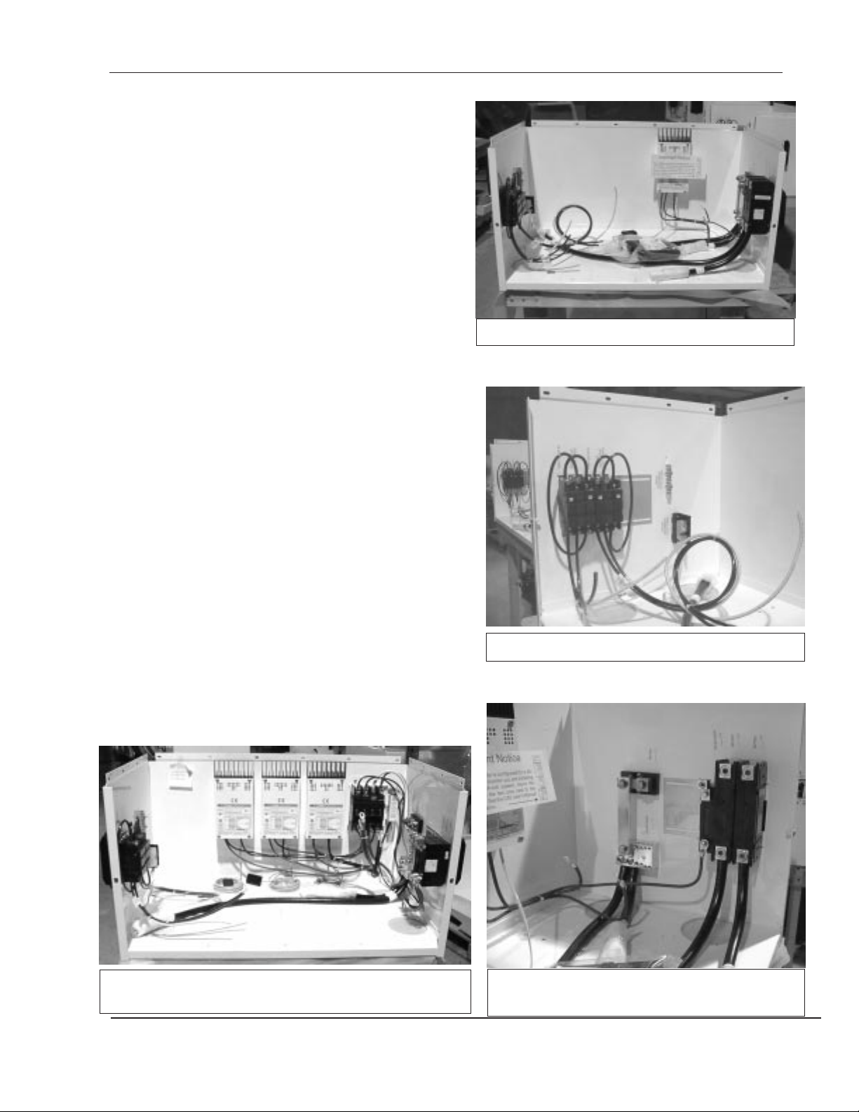
PM 175/250 D Front View
Invert PM to install feet; revert to continue. Remove
appropriate component instruction sheets and arrange in
order of installation. Gather all tools and components listed
in the instructions and place then nearby. Prepare
components as instructed on the component assembly
pages and set aside. When all components are prepared
and handy, assemble each component in the sequence
shown above, referring to the component assembly
instructions as required.
Front view of PM SW 175/250 D showing standard
components plus PVGFP and three C40’s w/BTS’s
PM 175/250 D Left Panel
PM SW 175/250 D right side panel including
DCBB, DC175/250, and PV
Copyright Trace Engineering Co., Inc. Telephone (360) 435-8826 Part Number 3471
5916 195th Street, NE Fax (360) 435-2229 Released: Thursday, April 29, 1999
Arlington, WA 98223 USA www.traceengineering.com
Page 26

4-14
Three-Phase Power Module
Copyright Trace Engineering Co., Inc. Telephone (360) 435-8826 Part Number 3471
5916 195th Street, NE Fax (360) 435-2229 Released: Thursday, April 29, 1999
Arlington, WA 98223 USA www.traceengineering.com
Page 27

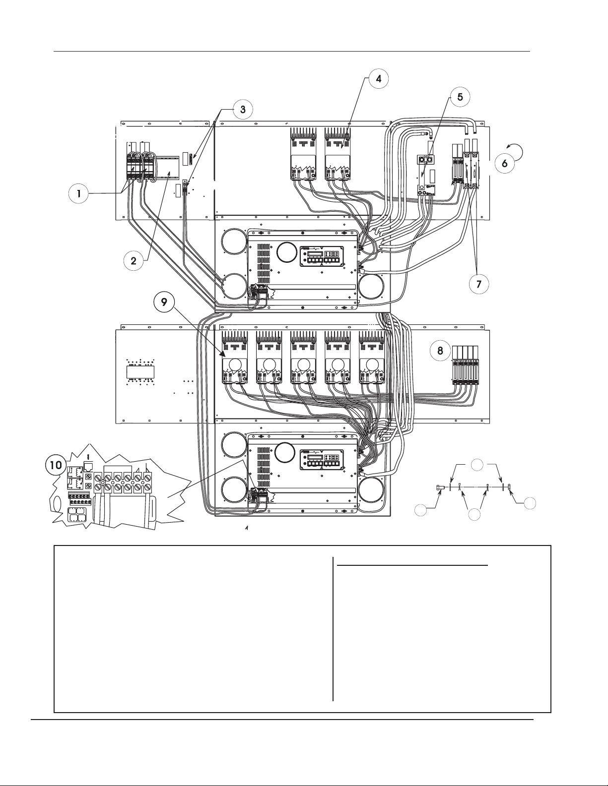
Three-Phase Power Module 4-15
1
11
2
12
3
13
4
4
5
9
6
14
7
4
4
8
10
15
16
17
14
15
4
18
B
A
C
D
19
17
20
Copyright Trace Engineering Co., Inc. Telephone (360) 435-8826 Part Number 3471
5916 195th Street, NE Fax (360) 435-2229 Released: Thursday, April 29, 1999
Arlington, WA 98223 USA www.traceengineering.com
Page 28

4-16 Sinewave 3 - Phase System
Sinewave 3 - Phase System
The Three-Phase Sinewave Power Module system consists of one PM module joined to two PM-ADD
enclosures. System includes three Door panels w/latches, screen and edge guard kit, one LID and an
outdoor sealing kit (not shown). The top most SW inverter is the master (Phase A) inverter connected to
the two slave inverters with a special 3-phase interface cable.
# Qty P/N PM OR PMO- Description
1 1 COVER acrylic breaker cover, see detail
2 1 IOX60 60-amp, Phase A bypass breaker
3 1 AC60-3 60-amp, 3-phase AC breaker
4 5 SLIDER unused breaker opening cover
5 1 NEUTRAL neutral bonding block includes ground bonding block shown above
6 1 MONITOR 3-phase monitor (optional); pass bypass breaker output from each inverter through the monitor,
7 1 DCBB ground bonding block; connect a black, 4/0 cable from the bottom of this block to each inverter battery
8 3 DC175or250 DC circuit breaker; connect a red 2/0 or 4/0 cable from the battery bank positive terminal to the
9 1 SWXXXX Phase A Sinewave inverter (master inverter)
10 1 COVER Lockable acrylic cover over the DC breakers; include Warning decal
11 1 COVER Cover for Phase B and C bypass breakers w/bypass warning decal
12 1 IOX60 Phase B bypass breaker
13 1 IOX60 Phase C bypass breaker
14 AR C40’s Optional C40 charge controllers. Mount in the sequence shown.
15 AR DC20/60/110 Optional PV array DC circuit breakers.
16 1 SWXXXX Phase B Sinewave inverter (slave)
17 2 COVER Lockable cover used over PV array breakers; see detail
18 1 BLANK Covers unused breaker opening in left wing panel of Phase C inverter enclosure.
19 1 SWXXXX Phase C Sinewave inverter (slave)
20 1 FEET Set of drilled brackets for mounting system to an appropriate foundation
3 DOOR Door assemblies (not shown)
1 ODTEK Sealing kit (not shown)
1 Screen and edgeguard kit (not shown)
1 Fastener kit; contains fasteners for stacking module and securing inverters
1 LID Lid for top module (not shown)
1 Three-phase interface cable (adjacent to 9-16-19)
INVERTER FASTENING DETAIL:
then to bottom of 60-amp, 3-phase AC breaker.
negative terminal. Connect a black 4/0 cable from the top of this assembly to each negative battery bank
terminal
top of each breaker; connect a red 4/0 cable from the bottom of each breaker to the positive battery
terminal of each Inverter.
A 6 425 ¼ - 20 X ¾” HH SS bolt
B 12 2147 ¼” external tooth starwasher
C 12 ¼” flat washer
D 6 444 ¼-SSHHnut
Copyright Trace Engineering Co., Inc. Telephone (360) 435-8826 Part Number 3471
5916 195th Street, NE Fax (360) 435-2229 Released: Thursday, April 29, 1999
Arlington, WA 98223 USA www.traceengineering.com
Page 29

3-Phase Assembly Sequence 4-17
3-Phase Assembly Sequence
1) Assemble each PM module according to the instructions found on each respective assembly sheet: Phase C module assembly
instructions; Phase B module assembly instructions; Phase A module assembly instructions.
2) Mount a 3-phase Sinewave inverter into Phase C module using the six bolts, 12 starwashers, 12 lock washers, and12 nuts provided
for this purpose.
3) Secure Phase C module to prepared pad using the lag bolts and washers as described on the FEET assembly instructions sheet.
4) Attach the prepared Phase B module to the Phase C module using all 14 fasteners. See Phase B module assembly instructions
5) Place the Phase C module AC wiring between the Phase C inverter and the bypass breaker in the Phase B module. Refer to the
IOX60 sheet for instructions.
6) Mount the Phase B inverter on the floor of the Phase B enclosure; don’t bolt it down yet. Connect Phase B module AC wiring between
the Phase B inverter and the IOX60 bypass.
7) Mount the Phase A module on top of the Phase B module. Secure with all 14 fasteners.
8) Connect Phase B and Phase C DC cabling between the inverters and the DC250 breakers in the Phase A cabinet.
9) Place the Phase A inverter in place on the floor of the Phase A module; don’t bolt it down yet.
10) Connect all Phase A AC cabling to the remaining IOX60 bypass.
11) Connect all Phase A DC cabling remaining to the DC breakers and C40’s where used.
12) Secure the Phase A inverter to the floor of the Phase A module with the fasteners provided for this purpose.
13) Plug the 3-Phase interface cable into the connector labeled “Series Stacking” on each inverter. The connector marked “A” plugs into
the Phase A inverter, “B” into Phase B inverter, and “C” into Phase C inverter.
14) Install the weatherproofing gasket on the facing edge of all three modules, and across the bottom edge of all three panels.
15) Turn all AC and DC breakers to the OFF position. DO NOT SKIP THIS STEP.
16) Turn the shorepower 3-phase AC circuit breaker to which you are attaching the Trace 3-Phase Power Module to the OFF position
and lock it to ensure that it cannot be turned to the On position.
17) Connect the AC cabling between the Trace 3-Phase Power Module and the shorepower 3-phase supply circuit breaker.
18) Inspect all AC and DC wiring connections and cabling to verify that all connections are properly completed.
19) When satisfied that all cabling connections are correct, perform the start-up procedure as described in the Trace Engineering
Three-Phase Power Module Installation and Operation Guide.
20) When satisfied with the operation of the Trace Three-Phase Power Module System, install the LID onto the Phase A module and
secure with all 6 fasteners.
21) Install a prepared DOOR panel on the Phase C module, then the Phase B module, and finally on the Phase A module. Lock all six
door LATCHES and remove keys. Provide the owner the Trace Engineering Three-Phase Power Module Installation and Startup Guide,
plus the SymCom Model 777 Electronic Overload Relay installation instructions, the Trace Engineering Sinewave Owners Manual, and
all other warranty cards and instructions.
22) Have a refreshing beverage and enjoy!
Copyright Trace Engineering Co., Inc. Telephone (360) 435-8826 Part Number 3471
5916 195th Street, NE Fax (360) 435-2229 Released: Thursday, April 29, 1999
Arlington, WA 98223 USA www.traceengineering.com
Page 30

4-18 3-Phase Assembly Sequence
#6 Three-Phase Monitor
#1 Cover Detail
#17 Cover Detail
#2&3 Detail
#11 PhaseB&CCover
#15 PV Array Breakers
Detail
#10 Phase A Detail
Copyright Trace Engineering Co., Inc. Telephone (360) 435-8826 Part Number 3471
5916 195th Street, NE Fax (360) 435-2229 Released: Thursday, April 29, 1999
Arlington, WA 98223 USA www.traceengineering.com
#8, DC Breakers
#12 & 13 Detail
Page 31

3-Phase Assembly Sequence 4-19
Phase C Module Assembly Instructions
Phase C module consists of a PM-ADD (page 6-5)
with two Blanks, edge guards, screens, one Sinewave
inverter, one DOOR with latches, FEET, a “Phase C”
decal, any excess C40’s and PV Array breakers, and
associated assembly hardware. Install the FEET first
(page 6-17), then the edge guards and screens, then
the Blanks ( page 6-9). Place the module on the pad
or platform and mark the location of each of the 10
anchor bolts ( page 6-18). Remove the module and
install the inverter in it. Drill anchor holes in the pad
and install expansion anchors. Place Phase C module
on the pad and install the lag screw anchors to secure
it in place. Attach “Phase C” decal to the front center
of the tray.
Phase B Module Assembly Instructions
Phase B module consists of a PM-ADD (which includes a DOOR),
equipped with two 60-amp IOX60 bypass breakers, one COVER, one
SLIDER, one BLANK, and edge guards. Assemble the Phase B
module on the workstand by first installing the two IOX60 bypass
breakers (page 5-19), then add a SLIDER to the unused breaker
openings (page 6-23), and edgeguards to the openings in the bottom.
Then install a BLANK (page 6-9) on the right side-panel and a
COVER (page 6-13) over the side-panel with breakers. Complete by
adding the appropriate decals.
If any C40’s ( page 5-9) and their associated DC breakers (page
5-12) are to be installed, the BLANK will not be required. Instead, an
additional SLIDER and COVER will be necessary.
Tools Required: 5/16 & 3/8” wrench and/or socket w/ratchet,#1&
# 2 straight-blade screw drivers, crimping and stripping tools.
Phase A Module Assembly Instructions
Phase A module includes a PM with FEET, DOOR, and LID, the
Phase A bypass breaker (page 5-19), a 60-amp 3-phase AC
breaker (page ), a neutral bonding block to which all three
neutrals from the inverters are connected (page 5-21), a DCBB
(page 5-16), a DC175/250 circuit breaker (page 5-13) for each of
the three inverters, two SLIDERs (page 6-23), two COVERs
(page 6-13), any optional equipment such as C40,s (page 5-9),
PVGFP (page ) or the 3-Phase Monitor, and related cabling and
fasteners. When adding optional equipment, it may be
necessary to locate some of the additional equipment in the free
space available in the other modules.
Copyright Trace Engineering Co., Inc. Telephone (360) 435-8826 Part Number 3471
5916 195th Street, NE Fax (360) 435-2229 Released: Thursday, April 29, 1999
Arlington, WA 98223 USA www.traceengineering.com
Page 32

4-20 3-Phase Assembly Sequence
This page intentionally left blank.
Copyright Trace Engineering Co., Inc. Telephone (360) 435-8826 Part Number 3471
5916 195th Street, NE Fax (360) 435-2229 Released: Thursday, April 29, 1999
Arlington, WA 98223 USA www.traceengineering.com
Page 33

5-1
Electrical Components Assembly Instructions
Copyright Trace Engineering Co., Inc. Telephone (360) 435-8826 Part Number 3471
5916 195th Street, NE Fax (360) 435-2229 Released: Thursday, April 29, 1999
Arlington, WA 98223 USA www.traceengineering.com
Page 34

5-2
Table of Contents
AC15/20/60 Front View ..............5-3
AC15/20/60 Front and Left View .........5-4
AC15, 20, 60 Assembly Sequence .....................5-4
AC60 3-Phase Breaker ..............5-5
AC15, 20, 60 Assembly Sequence .....................5-6
C40, C40K & VLC40 for DR Systems .......5-7
Wiring Instructions .............................5-7
C40, C40K & VLC40 for DR Systems .......5-8
C40, C40k & VLC40 for Sinewave Systems ...5-9
Wiring Instructions .............................5-9
DC20/60/110 ...................5-11
DC20/60/110 ...................5-12
DC175/250 ....................5-13
DC175/250 ....................5-14
DCBB/K/SW....................5-15
DCBB .......................5-16
DCBB .......................5-17
IOX60 Input/Output/Bypass Breaker ......5-19
IOX60 .......................5-20
NEUTRAL .....................5-21
Copyright Trace Engineering Co., Inc. Telephone (360) 435-8826 Part Number 3471
5916 195th Street, NE Fax (360) 435-2229 Released: Thursday, April 29, 1999
Arlington, WA 98223 USA www.traceengineering.com
Page 35

PMO-AC15/20/60 Front View 5-3
60-amp AC
Circuit Breaker
To AC Loads
Mount bracket
first, then
breaker
PMO-AC15/20/60 Front View
Used to connect an external AC source or load, these
breakers are installed as shown in the diagram above, and
wired according to your purpose. See diagrams on this and
the next page. Strip wire approximately .425” both ends
and cut to appropriate length.
PDBB
Preferred when used as subpanel. Maximum three
20-amps or four 15-amp breakers.
# Qty Part No. Description
1 1 3371 decal, “AC LOADS”
2 2 401 6-32 X 3/8” HH SS bolt
3 2 492 #6 starwasher, external teeth
4 2 wire lugs.
5 1 3299 15 amp QOU breaker
6 2 466 #6 SAE SS washer
7 2 440 6-32 HH SS nut
8 1 3171 service crimp
9 1 3202 decal: “To AC Hot Loads”
10 21” 2322 6 AWG Black THHN wire
3258 20 amp QOU breaker
3087 60 amp QOU breaker
Copyright Trace Engineering Co., Inc. Telephone (360) 435-8826 Part Number 3471
5916 195th Street, NE Fax (360) 435-2229 Released: Thursday, April 29, 1999
Arlington, WA 98223 USA www.traceengineering.com
Page 36

5-4 PMO-AC15/20/60 Front View
AC15, 20, 60 Assembly Sequence
1. Remove set screws from lugs on top and bottom of circuit
breaker
2. Rotate lugs 180° and replace set screws.
3. Attach service lugs to top lugs only
4. Attach a mounting bracket to the top and bottom of the PM in
the desired location. Insert a 6-32 x 3/8” bolt (401) equipped with
a #6 starwasher (492) into the appropriate bolt hole (top and
bottom) from the outside of the side panel; slide the bracket over
the bolt from the inside so that the ears are offset to the inside of
the enclosure. Slide a #6 SAE flat washer (466) over the bolt,
followed by a 6/32 nut (440). Do not tighten, just catch a few
threads.
5. Tilt the top of the circuit breaker while sliding it onto the ears of
the top mounting bracket. Repeat for the bottom mounting
bracket.
6. Align the circuit breaker with either the top or the bottom of the
breaker opening.
7 Tighten the mounting brackets onto the PM and torque to
10-15 foot pounds.
From Generator
To AC2
As Generator Breaker
8. When all circuit breakers and bypass disconnects are
mounted, install a SLIDER of unused breaker openings.
9. Install PM-SLIDER over the exterior of the circuit breaker
opening (do not over tighten)
10. Apply a decal (3371 “AC Loads”) over each AC load circuit
breaker.
11 Attach AC cabling and torque to 45 inch-pounds
As AC subpanel, three 20-amp or
four 15-amp maximum
To AC Loads
As independent bypass
to AC loads
Copyright Trace Engineering Co., Inc. Telephone (360) 435-8826 Part Number 3471
5916 195th Street, NE Fax (360) 435-2229 Released: Thursday, April 29, 1999
Arlington, WA 98223 USA www.traceengineering.com
Page 37

PMO-AC60 3-Phase Breaker 5-5
PMO-AC60 3-Phase Breaker
The 60-amp, three-phase AC breaker is used with
three-phase power modules only. It is mounted in the left
wing panel of the Phase A module, next to the Phase A
bypass breaker. It accepts its input from the three-phase
monitor, (when used) or directly from each individual
inverter bypass breaker (IOX60). A decal describing the
startup and shutdown procedure is mounted above the
breaker on the inside of the breaker cover.
AC60 3-phase breaker shown on right next to the
Phase B bypass breaker
The AC-60 three-phase circuit breaker is shown
in the top illustration. The exterior of the breaker
installation is shown on the left illustrating the
decals that describe the start-up and shut-down
procedure and the appropriate position of the
bypass breaker.
Copyright Trace Engineering Co., Inc. Telephone (360) 435-8826 Part Number 3471
5916 195th Street, NE Fax (360) 435-2229 Released: Thursday, April 29, 1999
Arlington, WA 98223 USA www.traceengineering.com
Page 38

5-6 PMO-AC60 3-Phase Breaker
Motor Minder
Ground Bonding Block
3-Phase AC Breaker
Phase A Bypass
Neutral Bonding Block
AC15, 20, 60 Assembly Sequence
6. Align the circuit breaker with either the top or the
1. Remove set screws from lugs on top and bottom of circuit
breaker
2. Rotate lugs 180° and replace set screws.
3. Attach service lugs to top lugs only
4. Attach a mounting bracket to the top and bottom of the PM
in the desired location. Insert a 6-32 x 3/8” bolt (401) equipped
with a #6 starwasher (492) into the appropriate bolt hole (top
and bottom) from the outside of the side panel; slide the
bracket over the bolt from the inside so that the ears are offset
to the inside of the enclosure. Slide a #6 SAE flat washer (466)
over the bolt, followed by a 6/32 nut (440). Do not tighten, just
catch a few threads.
5. Tilt the top of the circuit breaker while sliding it onto the ears
of the top mounting bracket. Repeat for the bottom mounting
bracket.
Copyright Trace Engineering Co., Inc. Telephone (360) 435-8826 Part Number 3471
5916 195th Street, NE Fax (360) 435-2229 Released: Thursday, April 29, 1999
Arlington, WA 98223 USA www.traceengineering.com
bottom of the breaker opening.
7 Tighten the mounting brackets onto the PM and
torque to 10-15 foot pounds.
8. When all circuit breakers and bypass disconnects
are mounted, install a SLIDER over unused breaker
openings.
9. Install PM-SLIDER over the exterior of the circuit
breaker opening (do not over tighten)
10. Apply a decal (3371 “AC Loads”) over each AC
load circuit breaker.
11. Attach AC cabling
Page 39

PMO-C40, C40K & VLC40 for DR Systems 5-7
Drill out the dimples at distance shown with 11/64” bit for
lower mounting holes only. Fasten with 10-32 x 1/2” bolts,
12
INVERTER (+)
9”
14
3.5”
INVERTER ( )−
13
6
15
11
16
WIRE
4
5
6
11” 12”
14”
23”
20” 26” 32” 38”
27”
18”
24”
33” 39” 45”
30”
PMO-C40, C40K & VLC40 for DR Systems
Place double-sided tape on the back panel of the C40 in the location
shown. Drill the dimples in the back plane of the PM in the approximate
location shown. When installing multiple C40’s, install them in the
sequence shown above the wire length table. Bundle excess or loose
wires.
Wiring Instructions
1. Follow the assembly instructions before wiring. Route the positive wire
through conduit (not included) to the DC side of the Power Module and
connect to the top of the PV array disconnect. Do not connect the array
positive directly to the C40 charge controller. Use a minimum of 6 AWG
wire. If more than one charge controller is utilized, the modules in the
array should be divided equally between the controllers.
2. Connect the PV array negative to the bonding block. Connect the
frames of the PV Modules to the bonding block through ground wiring. The
PV negative and battery negatives are connected at the negative bonding
block. Do not connect the charge controller battery negative directly to the
battery.
3. Route all battery temperature sensor cables through the opening in the
tray of the module at the bottom right rear behind the DC disconnect
breakers. This allows the BTS cable(s) to be routed along
with the battery cables. There may be multiple
temperature sensors depending on the total number of
charge controllers and inverters in the system. Utilize all
available temperature sensors to maximize system
performance. Connect the temperature sensors to the
charge controllers through one of the openings in the rear
of the PM with a plastic grommet protecting the edge.
Place all temp sensors on the same battery and in the
middle of the battery bank.
Qty Part No. Description
#
1 AR C40 or VLC40
2 2 3220 1.375” bushing
3 AR PMO-BTS battery temperature sensor
4 AR 2323 6 AWG cable* Red cable to DC175/250
5 AR 2323 6 AWG cable* Black cable to DCBB
6 AR 2323 6AWG cable* Red cable to PV
disconnect
7 2 6-32 SS nut
8 2 485 ¼” starwasher
9 1 1974-1 2/0 lug
10 2 492 #6 starwasher
11 2 401 6-32 HH SS capscrew
12 AR 3240 decal “Inverter (+)”
13 AR 3238 decal “Inverter (-)”
14 AR 2430 #6 AWG ring terminal
15 AR 2430 #6 AWG ring terminal
16 AR 716-1 #6 AWG ring terminal ¼” hole
10”
Copyright Trace Engineering Co., Inc. Telephone (360) 435-8826 Part Number 3471
5916 195th Street, NE Fax (360) 435-2229 Released: Thursday, April 29, 1999
Arlington, WA 98223 USA www.traceengineering.com
Page 40

5-8 PMO-C40, C40K & VLC40 for DR Systems
PMO-C40, C40K & VLC40 for DR Systems
This view illustrates the installation, mounting, and cabling
of the C40 options looking toward the left-hand cabinet
panel. PMO-C40 multipurpose controller includes a
user-selectable PV Charge Controller mode, a DC Load
Control mode, and a Diversion Load Control mode (the
controller can operate in only one mode at a time). In
addition, the PMO-C40 includes a 60 amp DC Heineman™
CD breaker, #6 AWG wiring with ring terminals, and all
mounting hardware. A 22-page operating manual for the
C40 controller is also included. The PMO-VLC40 is a
voltage limiting controller. It includes all of the items that
come with the PMO-C40, but uses a modified C4O for
systems that use PV modules generating high open circuit
voltage (over 70 volts DC) without batteries. The VLC40
# Qty Part No. Description
1 6” 3304 1” double-backed tape
2 4 486 #10 starwasher
3 4 411 10-32 x ½” HH SS bolt
4 2323 6 AWG cable w/ #3238 decal & 2430
ring terminal
5 2323 6 AWG cable w/ ring terminal & 716-1
6 2323 6 AWG cable w/ #3204 decal & 2430
ring terminal
7 1 PMO-DCBB DC bonding block
8 1 3224 Solar Array decal
9 4 442 10-32 HH SS capscrew
10 4 486 #10 star washer
11 1 2298 60-amp DC breaker
12 1 3233 ”Solar Array 1” decal
Tools Required: knife or scissors,#1 and #2 straight-blade screwdriver,
5/16 & 7/16” socket, wrench, or nut driver, wire-stripping pliers, ¼” socket
or wrench.
automatically limits voltage to less than 70 volts DC.
PMO-C40K Installation Kit. The PMO-C40K installation kit
includes everything that the PMO-C40 includes except the
C40 itself, and the C40 operating manual.
Copyright Trace Engineering Co., Inc. Telephone (360) 435-8826 Part Number 3471
5916 195th Street, NE Fax (360) 435-2229 Released: Thursday, April 29, 1999
Arlington, WA 98223 USA www.traceengineering.com
Page 41

PMO-40, C40k & VLC40 for Sinewave Systems 5-9
Drill two half-shears at distance shown with 11/64” bit for lower
mounting holes only. Fasten with 10-32 x 1/2” bolts,
3.5”
10”
12
INVERTER (+)
9”
INVERTER ( )−
13
From PV Array Positive (+)
10
11
6
14
15
16
WIRE
4
5
6
Wire Length Table. Wire length is based upon the mounting
location of the C40. Do not exceed four C40’s with DC175
disconnect, or five C40’s with a DC250 disconnect. Do not
exceed DC disconnect’s current rating
.
PMO-40, C40k & VLC40 for Sinewave Systems
The wiring scheme shown in this view meets NEC code requirements by
using the battery disconnect of the inverter as the overload/disconnect
device. Alternative methods of wiring the C40’s may be needed depending
upon your application. Kits are shipped with maximum wire lengths
pre-cut. Trimmed the uncrimped end to the length found in the Wire
Length table according to the C40’s mounting position.
Place double-sided tape on the back panel of the C40 in the location
shown. Drill the dimples in the back plane of the PM in the approximate
location shown. When installing multiple C40’s, install them in the
sequence shown above the wire length table. Bundle excess or loose
wires. This option requires the use of a bare grounding conductor between
the DCBB and a rod or pipe driven into the earth.
Qty Part No. Description
#
1 AR PMO-C40/K charge, load, or diversion controller
2 2 3220 1.375” thermoplastic knockout bushing
3 1 PMO-BTS battery temperature sensor with cable
4 AR 2323 6 AWG THHN red cable to inverter positive terminal
5 AR 2323 6 AWG THHN Black negative cable to inverter
6 AR 2323 6 AWG THHN Red positive cable to PV circuit breaker
7 2 442 6-32 HH SS nut
8 2 486 #10 starwasher
9 1 1974-1 2/0 barrel lug Connect the PV (+) to this lug.
10 4 492 #6 starwasher
11 2 401 6-32 HH SS bolt
negative terminal
12 AR 3240 decal “Inverter (+)”
13 AR 3238 decal “Inverter (-)”
14 AR 2430 #6 AWG ring terminal
15 AR 2430 #6 AWG ring terminal
16 AR 716-1 #6 AWG ring terminal w/ ¼” hole
17 XXX wire tie (not shown)
*Refer to wire length table to determine length of each cable by its position.
Mount C40s in sequence shown above table. AR = as required.
Wiring Instructions
1. Follow the assembly instructions before wiring. Route
the PV array positive wire through conduit (not included)
to the DC side of the PM and connect to the top of the PV
array disconnect. Do not connect the array positive
directly to the C40 charge controller. If more than one
charge controller is utilized, the modules in the array
should be divided equally between the controllers.
2. Connect the PV array negative to the ground bonding
block (DCBB). Connect the frames of the PV modules to
the ground bonding block through the negative array
cables. The PV negative and battery negatives are
connected at the ground bonding block. Do not connect
the charge controller battery negative directly to the
battery.
Copyright Trace Engineering Co., Inc. Telephone (360) 435-8826 Part Number 3471
5916 195th Street, NE Fax (360) 435-2229 Released: Thursday, April 29, 1999
Arlington, WA 98223 USA www.traceengineering.com
Page 42

5-10 PMO-40, C40k & VLC40 for Sinewave Systems
the items that come with the C40, but uses a modified C40
3. Route all battery temperature sensor (BTS) cables through the opening
in the tray of the module at the bottom right rear behind the DC disconnect
breakers. This allows the BTS cables to be routed along with the battery
cables. There may be multiple temperature sensors depending on the
number of charge controllers and inverters in the system. Utilize all
available temperature sensors to maximize system performance. Connect
for systems that use PV modules generating high
open-circuit voltage (over 70 volts DC) without batteries.
The VLC40 automatically limits voltage to less than 70 volts
DC. The PMO-C40K installation kit includes everything that
the PMO-C40 includes except the C40 and the C40
operating manual.
the temperature sensors to the charge controllers through one of the
Qty Part No. Description
openings in the rear of the PM with a plastic grommet protecting the edge.
Place all temp sensors on the same battery and in the middle of the battery
bank.
The top view illustrates the installation, mounting, and cabling of the C40
option looking toward the right-hand cabinet panel. The C40 multipurpose
controller has three modes: PV charge control mode, DC load control
mode, and diversion load control mode (the controller can operate in only
one mode at a time). In addition, the C40 option includes a 60-amp
Heineman™ DC breaker, #6 AWG wiring with ring terminals, and all
mounting hardware. A 24-page operating manual for the C40 controller is
also included. The VLC40 is a voltage limiting controller. It includes all of
Copyright Trace Engineering Co., Inc. Telephone (360) 435-8826 Part Number 3471
5916 195th Street, NE Fax (360) 435-2229 Released: Thursday, April 29, 1999
Arlington, WA 98223 USA www.traceengineering.com
#
1 6” 3304 1” square of double-backed tape
2 2 486 #10 starwasher
3 2 411 10-32 x ½” HH SS bolt
4 AR 2323 6 AWG cable w/ 3204 decal & 2430 ring
5 AR 2323 6 AWG cable with 2430 ring terminal &
6 AR 2323 6 AWG cable & 716-1 ring terminal to
7 1 DCBB DC bonding block
8 1 3224 “Solar Array (-)” decal
9 2 442 10-32 HH SS capscrew
10 2 486 #10 star washer
11 1 2298 60-amp Heineman™ DC breaker
12 1 3233 ”Solar Array (+)” decal
3228 decal to inverter negative terminal
terminal to inverter positive terminal
60-amp Heineman DC breaker
Page 43

PMO-DC20/60/110 5-11
3
To DC Loads
2
To Battery (+)
From PV array (+)
To C40 PV (+)
positive terminal
From C40 battery
positive terminal
DCXX as a disconnect for an PV array positive.
To Battery (+)
From DC Charging Source
To Battery (+)
2
2
DCXX as disconnect between charging source and battery
DCXX as a disconnect between battery positive and load
PMO-DC20/60/110
your PV positive to the top of the breaker, and routea6AWG
cable from the bottom of the DCXX to the top of your
Assembly: DC20/60/110 circuit breaker/disco connects are installed
DC175/250 breaker.
adjacent to the DC175/250 breakers on the right side panel for SW
systems and on the left side panel for DR systems. Begin the installation
by removing the topmost nut and one flat washer on the back of the circuit
Tools Required: ¼”, 7/16” & 3/8” socket or wrench; #2
flat-blade screwdriver; wire stripper, crimping tool.
breaker and install the barrel lug over the stud. Replace the flat washer
Qty Part No. Description
followed by the starwasher and the nut, then tighten. Insert the breaker in
the side panel from the inside and secure with two 6-32 x 3/8” machine
screws with #6 internal tooth starwashers. When used with the C40
charge controller, connect the C40 Battery (+) terminal to the bottom of the
DCXX and your PV array positive to the barrel lug at the top of the DCXX
to complete the installation. When a charge controller is not used, connect
Copyright Trace Engineering Co., Inc. Telephone (360) 435-8826 Part Number 3471
5916 195th Street, NE Fax (360) 435-2229 Released: Thursday, April 29, 1999
Arlington, WA 98223 USA www.traceengineering.com
#
1 1 2957 20 amp breaker or
2 19” 2323 #6 AWG Red THHN wire used with 20, 60-amp
3 2 716-1 #6 AWG ring terminal w/ ¼” hole
4 1 1974-1 barrel lug terminal
2298 60 amp breaker or
2249 110 amp breaker
3302 #2 AWG Red THHN use with 110-amp
3300 #2 AWG ring terminal
Page 44

5-12 PMO-DC20/60/110
DCXX
breaker
with barrel
lug
10
installed
PMO-DC20/60/110
Tools Required: ¼”, 7/16” & 3/8” socket or wrench, 1/4” flat-blade
screwdriver
installed adjacent to the DC175/250 breakers on the right side panel for
SW systems and on the left side panel for DR systems. Begin the
installation by removing the topmost nut and one flat washer on the back of
the circuit breaker and install the barrel lug over the stud. Replace the flat
washer followed by the starwasher and the nut, then tighten. Insert the
breaker in the side panel from the inside and secure with two 6-32 x 3/8”
machine screws with #6 internal tooth starwashers. Install the 6 AWG
cable between the hot side of one of the DC175/250 breakers and the
Copyright Trace Engineering Co., Inc. Telephone (360) 435-8826 Part Number 3471
5916 195th Street, NE Fax (360) 435-2229 Released: Thursday, April 29, 1999
Arlington, WA 98223 USA www.traceengineering.com
. Assembly: DC20/60/110 DC circuit breaker/disconnect is
bottom of the DC20/60/110 and the DC60. For PV
systems, connect the DC60 between the PV array and
the C40 charge controller.
#
Qty Part No. Description
5 2 1/4-20 SS nut
6 2 485 ¼” internal tooth starwasher
7 1 486 #10 external tooth starwasher
7 1 2292 1/4-20 x 7/16” HH SS bolt
8 2 492 #6 internal tooth starwasher
9 2 401 6-32 X 3/8”HH SS machine screw
Page 45

PMO-DC175/250 5-13
4
5
6
One SW Two SW
RED
BLACK
RED
RED
BLACK
BLACK
3-phase SW
57”
57”
One DR
Two DR
PMO-DC175/250
DC 175/250 amp direct current circuit breakers. One
required for each inverter installed. Route DC supply
through these breakers. Refer to wire length table to
determine the length of battery cables. Fabricate cables as
shown in 7 through 10 below:
Copyright Trace Engineering Co., Inc. Telephone (360) 435-8826 Part Number 3471
5916 195th Street, NE Fax (360) 435-2229 Released: Thursday, April 29, 1999
Arlington, WA 98223 USA www.traceengineering.com
# Qty Part No. Description
1 AR 3204 decal: “Inverter (+)”
2 AR 2079 250 amp circuit breaker, DR2412,
DR3624;
SW2512, SW4024, SW5548
DR1524,
DR2424; SW4048
3 1 2385 decal:”Battery Disconnect”
4 6 425 1/4-20 X ¾” HH SS capscrew
5 12 2147 ¼” external tooth starwasher
6 1 2358 decal “Inverter #1” on breaker handle
2116 175 amp circuit breaker, DR1512,
1 3369 decal “Inverter #2” on breaker handle
1 2259 decal “inverter #3” on breaker handle
Page 46

5-14 PMO-DC175/250
Before reversing lug
After reversing lug
Connect Battery Negatives Here
#
PMO-DC175/250
Use 250-amp circuit breaker for DR2412, 3624; use 175-amp circuit
breaker for DR1512,1524, 2424, and SW4048. Wire length depend on the
number of inverters and mounting position in the power module cabinet.
Refer to wire length table to determine length of Inverter (+) and Inverter (-)
cables for your installation. One PMO-DC250 (175) is needed for each
inverter installed. Rotate cable lugs on top and bottom 180 degrees prior
to installing the breaker in the enclosure (see illustrations above) Strip
insulation from cables 0.425-inch on each end and install ring terminals.
Apply appropriate color heat shrink and tubular lugs.
Copyright Trace Engineering Co., Inc. Telephone (360) 435-8826 Part Number 3471
5916 195th Street, NE Fax (360) 435-2229 Released: Thursday, April 29, 1999
Arlington, WA 98223 USA www.traceengineering.com
Qty Part No. Description
1 1 3238 decal; “Inverter (-)” on battery cable
2 AR US battery cables (not included)
3 1 DCBB/Kit/SW DC Negative Bonding Block (not included)
4 1 3231 decal: “Battery (+)”
5 1 2079 circuit breaker, 250-amp DC
6 1 3204 decal; “Inverter (+),” ( battery cable not
7 2 2087 Heat Shrink Black w/logo
8 2 722-1 ring terminal for 4/0 AWG cable
9 2 2086 heat shrink, red w/logo
2116 circuit breaker, 175-amp DC
included)
722-2 ring terminal for 2/0 AWG cable
Page 47

PMO-DCBB/Kit/SW/DR 5-15
PMO-DCBB/Kit/SW/DR
The PMO-DCBB kit includes a DC negative bonding block with a
500-amp, 50-millivolt shunt and a bus bar. Add the /SW or /DR
suffix to specify the type of inverter used.
Tools Required: 5/16, 3/8, 9/16, wrenches; 13/64” drill bit, 1/8 &
5/16” Allen wrench, straight slot screwdriver
Assembly Sequence Pre-assemble the bonding block by
installing the set screws using a flat-bladed screwdriver and Allen
wrenches as required. Place a #10 internal-tooth starwasher
(486) over a 10-32 x 3/8” machine screw. Drill out the dimples and
insert a machine screw in one of the lower holes from the outside
of the side panel. Place a ¼” external tooth starwasher over the
machine screw on the inside of the side panel. Support the
aluminum bonding block on the inside of the side panel and start
the machine screw in the appropriate pre-drilled and tapped hole
in the bonding block. Repeat the procedure for the other tapped
hole in the bonding block. Don’t forget to place an external tooth
starwasher between the bonding block and the enclosure on each
machine screw. This assures an electrical bond between the
bonding block and the enclosure. Tighten to 10-12 foot pounds. It
may be easiest to insert the negative battery cables to
the bonding block prior to installing it on the side panel.
When the bonding block is installed, drill out two
dimples above the block for the shunt. Insert a 10-32 x
¾” machine screw equipped with an external tooth
starwasher through the drilled-out dimple and into the
holes in the shunt base. Secure the shunt base with
#10 internal tooth starwasher and a 10-32 SS nut. Do
not tighten at this time. Align the five bus bars and
secure one end of them to the bonding block with one
of the 3/8-16 x ¾” bolts equipped with a 3/8” lock
washer. Swing the bars into position over the hole in
the shunt and secure with the other 3/8-16 x ¾” bolts.
Tight to 10-12 foot pounds. Apply decal 2507 (ground
symbol) to the bonding block
# Qty Part No. Description
1 1 3232 decal: “Battery (-)”
2 1 3000 bonding block: DR system
2 4 2213 set screw, 1/4-20 x ½” zinc
3 1 2507 decal: earth ground symbol
4 2 2212 set screw, 5/16-18 x ½” zinc
5 2 2211 set screw, 7/16-14 x ½” , zinc
6 2 3167 set screw, 5/8-11 x 1” zinc plate
3001 bonding block: SW system
Copyright Trace Engineering Co., Inc. Telephone (360) 435-8826 Part Number 3471
5916 195th Street, NE Fax (360) 435-2229 Released: Thursday, April 29, 1999
Arlington, WA 98223 USA www.traceengineering.com
Page 48

5-16 PMO-DCBB/Kit/(SW)(DR)
DCBB shown with DC175/250 installed
PMO-DCBB/Kit/(SW)(DR)
All DC negative ground cables are attached to this
ground bus. Battery ground cables must be routed
through the shunt in order to enable accurate current
reporting by the inverters. Connect inverter DC
negative cables to the bottom of the DCBB, shown in
the photo above with a DC175/250 installed. Connect a
bare ground conductor from the bottom of the DCBB to
a copper or iron rod driven into the ground to form a
# Qty Part No. Description
1 1 3017 lock, washer 3/8” SS split ring
2 3 3016 bolt, 3/8-16 x ¾” SS HH
3 2 442 nut, 10-32
SS
4 2 486 star washer, #10 internal tooth SS
5 1 2377-1 shunt, 500v/50mA for PVGFP
6 2 486 star washer, #10 internal tooth SS
7 2 2845 machine screw, 10-32 x ¾” HH SS
8 5 2997 buss bars for shunt
9 2 3362 machine screw, 10-32 x 3/8” HH SS
10 2 486 star washer, #10 internal tooth SS
11 2 2147 star washer, external tooth ¼” SS
ground rod.
Copyright Trace Engineering Co., Inc. Telephone (360) 435-8826 Part Number 3471
5916 195th Street, NE Fax (360) 435-2229 Released: Thursday, April 29, 1999
Arlington, WA 98223 USA www.traceengineering.com
Page 49

PMO-DCBB 5-17
PMO-DCBB
All three inverter negative terminals are
The DCBB, shown here in a 3-phase installation alongside
three DC175/250 inverter positive breakers, provides a
ground bond for all of the inverter negatives. The 50mV,
connected by 4/0 or 2/0 cables to the bottom of
the DCBB bonding block as shown in the photo
above.
500-amp shunt that is a part of the DCBB provides an
interface for an ammeter or battery monitor such as the
Trace Meter. All DC current must pass through the shunt
on the DCBB in order for the battery amp-hour meter to be
accurate.
Copyright Trace Engineering Co., Inc. Telephone (360) 435-8826 Part Number 3471
5916 195th Street, NE Fax (360) 435-2229 Released: Thursday, April 29, 1999
Arlington, WA 98223 USA www.traceengineering.com
Page 50

5-18 PMO-DCBB
This page intentionally left blank.
Copyright Trace Engineering Co., Inc. Telephone (360) 435-8826 Part Number 3471
5916 195th Street, NE Fax (360) 435-2229 Released: Thursday, April 29, 1999
Arlington, WA 98223 USA www.traceengineering.com
Page 51

PMO-IOX60 Input/Output/Bypass Breaker 5-19
From AC Supply
To AC Loads
Rotate lugs180 before mounting breaker°
From Inverter
To Inverter
PMO-IOX60 Input/Output/Bypass Breaker
The IOX60 bypass breaker is a pair of 60-amp breakers
(one SPST and one DPST) assembled with a lockout rocker
that allows only one of the breakers to be in the On position
at a time. This enables you to bypass the inverter when
another source of AC power is available which is useful
when servicing the inverter. In normal operation, AC power
passes through the inverter to the AC loads, enabling the
inverter to monitor the AC supply and charge the batteries.
In the event of an interruption of external AC power, the
To bypass inverter, throw left-hand breaker to On
position. For Inverter power, throw right-hand
breaker to the On position
inverter can automatically come On and supply
AC power to the AC loads. Install the rocker by
inserting the lower tang into the bottom of the
breaker, then bend the upper tang into place. See
the directions provided with the breaker.
# Qty Part No. Description
1 6 401 machine screw, 6-32 x 3/8” HH SS
2 6 492 star washer, internal tooth #6
3 2 3171 service clamp
4 6 466 #6 flat washer SAE SS
5 6 440 6-32 nut SS
Copyright Trace Engineering Co., Inc. Telephone (360) 435-8826 Part Number 3471
5916 195th Street, NE Fax (360) 435-2229 Released: Thursday, April 29, 1999
Arlington, WA 98223 USA www.traceengineering.com
Page 52

5-20 PMO-IOX60
LEFT INTERIOR VIEW
16
17
PMO-IOX60
# Qty Part No. Description
1 1 2383 decal “Residence Wiring Switch”
2 1 2356 decal “Inverter Bypass”
3 1 2357 decal “Normal Operation”
4 1 2346 bypass interlock
5 1 2358 decal “Inverter 1”
6 1 2359 decal”Inverter 2”
7 1 3200 decal “From AC Hot Utility/Generator”
8 1 3202 decal “To AC Hot Loads”
Copyright Trace Engineering Co., Inc. Telephone (360) 435-8826 Part Number 3471
5916 195th Street, NE Fax (360) 435-2229 Released: Thursday, April 29, 1999
Arlington, WA 98223 USA www.traceengineering.com
9 6” 2322 6 AWG Blk THHN stranded wire
10 1 3171 service clamp — rotate 180° before
installing breaker
11 1 3097 breaker, 60-amp QOU260
12 1 3087 breaker, 60-amp QOU160
13 15” 2322 6 AWG Blk THHN stranded wire
14 1 3239 decal “Inverter Out”
15 1 3235 decal “Inverter In”
16 2 706 cable tie: 3.9” x .10”
17 2322 wire 6 AWG Blk THHN stranded
Page 53

PMO-NEUTRAL 5-21
PMO-NEUTRAL
PMO-Neutral includes a neutral bonding block capable of
accepting four neutral leads ranging from 14 AWG to 4
AWG and one 2/0 AWG cable. If additional capacity is
required, a second neutral bonding block can be ‘snapped’
to the first. A ground bonding block is also included as part
# Qty Part No. Description
1 2 3363 MS 10-32 X 1” HH SS
2 2 486 #10 star washer internal tooth SS
3 1 3364 Ground bar kit Square D
4 2 486 #10 star washer external thread SS
5 2 442 10-32 HH SS nut
6 1 PMO-PDBB bonding block
7 2 486 #10 star washer SS internal tooth
8 2 2845 10-32 X ¾” MS HH SS
of the PMO-Neutral option. Drill the appropriate dimples
with an 11/64 inch bit to mount the bonding blocks.
Copyright Trace Engineering Co., Inc. Telephone (360) 435-8826 Part Number 3471
5916 195th Street, NE Fax (360) 435-2229 Released: Thursday, April 29, 1999
Arlington, WA 98223 USA www.traceengineering.com
Page 54

5-22 PMO-NEUTRAL
This page intentionally left blank.
Copyright Trace Engineering Co., Inc. Telephone (360) 435-8826 Part Number 3471
5916 195th Street, NE Fax (360) 435-2229 Released: Thursday, April 29, 1999
Arlington, WA 98223 USA www.traceengineering.com
Page 55

6-1
Cabinet Components
Copyright Trace Engineering Co., Inc. Telephone (360) 435-8826 Part Number 3471
5916 195th Street, NE Fax (360) 435-2229 Released: Thursday, April 29, 1999
Arlington, WA 98223 USA www.traceengineering.com
Page 56

6-2
This page intentionally left blank.
Copyright Trace Engineering Co., Inc. Telephone (360) 435-8826 Part Number 3471
5916 195th Street, NE Fax (360) 435-2229 Released: Thursday, April 29, 1999
Arlington, WA 98223 USA www.traceengineering.com
Page 57

PM 6-3
1
2
3
6
4
a
7
8
5
PM
The PM is the basic power module component. PM components are
fabricated from 0.090 T6061 aluminum plate, and are powder-coated to
prevent corrosion (except the blanks for unused breaker openings).
Included are the lid, the back and sides, two blanks, the door and
associated baffles and screens, door latches, neoprene gaskets, and
aluminum brackets for securing the module to a concrete pad or wooden
platform. The gaskets, baffles, and screens for the door and cabinet
bottom prevent insects and small animals from entering the cabinets.
Install the neoprene perimeter gasket only after all PM’s and PM-ADD’s
have been set atop each other to ensure complete sealing.
7
c
b
7
9
#
Qty Part No. Description
1 1 LID
2 1 ELEC-MOD (back & sides)
3 2 BLANK
4 1 DOOR
5 1 LATCH
6 1 FEET
7a 1 PM mounting hardware includes 16 each: 401
bolts,
440 nuts, 466 flat washers, 492 internal starwashers
7b 1 inverter fastener assortment includes 6 each:
425
bolts, 444 nuts, 485 internal starwashers, 468
7c 1 module fastener assortment includes 14 each:
3190
carriage bolts, 3192 nuts, 485 internal starwashers,
flatwashers, 2147 external starwashers.
2147 external starwashers, 465 flat washers.
Copyright Trace Engineering Co., Inc. Telephone (360) 435-8826 Part Number 3471
5916 195th Street, NE Fax (360) 435-2229 Released: Thursday, April 29, 1999
Arlington, WA 98223 USA www.traceengineering.com
Page 58

6-4 PM
This page intentionally left blank.
Copyright Trace Engineering Co., Inc. Telephone (360) 435-8826 Part Number 3471
5916 195th Street, NE Fax (360) 435-2229 Released: Thursday, April 29, 1999
Arlington, WA 98223 USA www.traceengineering.com
Page 59

PM ADD 6-5
AB
PM ADD
PM ADD is an enclosure which does not include
FEET or a LID. It is used as stacking enclosure atop
a PM. Identical in every other respect, PM ADD is
used for adding equipment including batteries, an
inverter, charge controllers, or what ever you like. It
is fabricated from the same high-quality material as
the PM module.
Copyright Trace Engineering Co., Inc. Telephone (360) 435-8826 Part Number 3471
5916 195th Street, NE Fax (360) 435-2229 Released: Thursday, April 29, 1999
Arlington, WA 98223 USA www.traceengineering.com
C
# Qty Part No. Description
1 1 ELEC-MOD Side, back & floor panel
2 2 BLANK Cover for unused breaker
openings
3 1 DOOR Ventilated door panel w/ baffle &
screen
4 2 LATCH Cam-type latches, locks are
optional
Use the fasteners shown in the inset above and listed below to secure
the ADD to the enclosure or base.
A 3190 14 10-24X1/2” carriage bolts
B 465 14 #10 SAE flat washer
Page 60

6-6 PM ADD
This page intentionally left blank.
Copyright Trace Engineering Co., Inc. Telephone (360) 435-8826 Part Number 3471
5916 195th Street, NE Fax (360) 435-2229 Released: Thursday, April 29, 1999
Arlington, WA 98223 USA www.traceengineering.com
Page 61

PM-EXT 6-7
AB
PM-EXT
PM-EXT is an extension that fits atop a regular PM or
PM-ADD to add height. It is used for unusually high
batteries or other components that require more
clearance than afforded by the PM or PM ADD.
PM-EXT is constructed of the same high-quality
materials, and is powder-coated for long life.
Copyright Trace Engineering Co., Inc. Telephone (360) 435-8826 Part Number 3471
5916 195th Street, NE Fax (360) 435-2229 Released: Thursday, April 29, 1999
Arlington, WA 98223 USA www.traceengineering.com
C
# Qty Part No. Description
1 1 electro-mode extension for a PM
2 2 BLANK plug for unused breaker opening
3 1 DOOR
4 2 Latch to retain door - locks optional
The following fasteners are used to secure the EXT to an enclosure or
braces around the bottom edge.
A 14 3190 10-24 X ½” carriage bolts
B 14 465 #10 SAE flat washer
C 14 3192 10-24 nut
Page 62

6-8 PM-EXT
This page intentionally left blank.
Copyright Trace Engineering Co., Inc. Telephone (360) 435-8826 Part Number 3471
5916 195th Street, NE Fax (360) 435-2229 Released: Thursday, April 29, 1999
Arlington, WA 98223 USA www.traceengineering.com
Page 63

PMO-BLANK 6-9
1
3
2
PMO-BLANK
PMO-BLANK is a 0.080” aluminum plate used to cover the circuit breaker openings in the wing
panels of the PM and PM-ADD. Install these blanks on the outside of the wing panel using the six
self-tapping stainless steel screws. Place a bead of silicone between the blank and the wing panel
to prevent the entry of moisture or pesky little bugs.
Copyright Trace Engineering Co., Inc. Telephone (360) 435-8826 Part Number 3471
5916 195th Street, NE Fax (360) 435-2229 Released: Thursday, April 29, 1999
Arlington, WA 98223 USA www.traceengineering.com
# Qty Part No. Description
1 6 3212 8-32 x 3/8” self-tapping SS screws
2 1 PMO-BLANK
3 RTV silicone
Page 64

6-10 PMO-BLANK
This page intentionally left blank.
Copyright Trace Engineering Co., Inc. Telephone (360) 435-8826 Part Number 3471
5916 195th Street, NE Fax (360) 435-2229 Released: Thursday, April 29, 1999
Arlington, WA 98223 USA www.traceengineering.com
Page 65

PMO-BRACE 6-11
PMO-BRACE
Brace is an aluminum channel used to reinforce the bottom
of the PM and PM-ADD to support extra-heavy loads, such
as a battery bank. Install the brace using the fasteners
provided, and tighten to 25 inch-pounds.
Copyright Trace Engineering Co., Inc. Telephone (360) 435-8826 Part Number 3471
5916 195th Street, NE Fax (360) 435-2229 Released: Thursday, April 29, 1999
Arlington, WA 98223 USA www.traceengineering.com
# Qty Part No. Description
1 1 PM Power Module
2 5 3191 10-24 x 1” SS carriage bolt
3 1 3284 tray brace
4 1 465 #10 SAE SS flatwasher
5 5 3192 10-24 SAE nut
6 PM or PM-ADD cabinet
Tools Required;
Page 66

6-12 PMO-BRACE
This page intentionally left blank.
Copyright Trace Engineering Co., Inc. Telephone (360) 435-8826 Part Number 3471
5916 195th Street, NE Fax (360) 435-2229 Released: Thursday, April 29, 1999
Arlington, WA 98223 USA www.traceengineering.com
Page 67

PMO-COVER 6-13
PMO-COVER
PMO-COVER is a lockable, black hinged cover that prevents
unauthorized tampering with the breakers. These covers are
provided with a foam gasket to provide protection from the insects
and the elements, and a lock hasp to prevent unauthorized
tampering. The cover lid is also an ideal location for appropriate
# Qty Part No. Description
1 neoprene gasket
2 1 retaining clip
3 1 cover
4 1 base
5 6 8-32 x 3/8” self tapping HH screws
6 1 locking clip
warning decals and identification labels.
Copyright Trace Engineering Co., Inc. Telephone (360) 435-8826 Part Number 3471
5916 195th Street, NE Fax (360) 435-2229 Released: Thursday, April 29, 1999
Arlington, WA 98223 USA www.traceengineering.com
Page 68

6-14 PMO-COVER
This page intentionally left blank.
Copyright Trace Engineering Co., Inc. Telephone (360) 435-8826 Part Number 3471
5916 195th Street, NE Fax (360) 435-2229 Released: Thursday, April 29, 1999
Arlington, WA 98223 USA www.traceengineering.com
Page 69

PM-DOOR 6-15
14
11
12
13
PM-DOOR
DOOR provides locking (locks optional) weather-tight
access to the power module. The screen and water baffle
prevent insects and water from entering. The door is
fabricated from powder-coated 0.090 aluminum for long life.
See reverse for door assembly instructions. See Latch for
latch assembly instructions. The “Trace Power Systems”
decal is usually affixed only to the module that receives a
# Qty Part No. Description
1 4 440 6-32 SS HH nut
2 4 466 #6 SAE flat washer SS
3 1 3214 water baffle
4 1 3215 12” x 24” wire bug screen
5 1 1710 RTV 108 silicone
6 1 Door
7 1 3355 UL1741 label
1 2320-1 decal “Trace Power Systems” applied to
bottom of door when and included with PM-LID
8-15 Latch cam-type latches; locks and keys optional
lid.
Copyright Trace Engineering Co., Inc. Telephone (360) 435-8826 Part Number 3471
5916 195th Street, NE Fax (360) 435-2229 Released: Thursday, April 29, 1999
Arlington, WA 98223 USA www.traceengineering.com
15
Page 70

6-16 PM-DOOR
This page intentionally left blank
Copyright Trace Engineering Co., Inc. Telephone (360) 435-8826 Part Number 3471
5916 195th Street, NE Fax (360) 435-2229 Released: Thursday, April 29, 1999
Arlington, WA 98223 USA www.traceengineering.com
Page 71

PM-FEET 6-17
PM-FEET
FEET are required to meet the UL listing requirement for installation. The items with part number
US are ‘User-Supplied’ and are not included in the kit. Secure the enclosures to a concrete slab or
timbers before installing any additional equipment, especially batteries. .Tools Required: 5/16”
open, closed, or socket wrench; torque wrench
Assembly: Set the PM (sides and bottom) inverted upon the work table and attach the feet (if unit
is to be the only or the bottom unit of the stack). Secure the feet to the PM with 14 10-24 x 1.5"
carriage bolts provided. Place an internal-tooth starwasher on the bolt, insert through the PM and
then the bracket, place a flatwasher over the bolt and secure with a 10-24 nut. Repeat 13 times to
secure the brackets on three sides. Tighten to 10-12 foot pounds with 5/16" wrench, socket, or nut
driver. Starwashers have a sharp and a smooth side. Always place the sharp side against the
powder-coated metal.
Copyright Trace Engineering Co., Inc. Telephone (360) 435-8826 Part Number 3471
5916 195th Street, NE Fax (360) 435-2229 Released: Thursday, April 29, 1999
Arlington, WA 98223 USA www.traceengineering.com
# Qty Part No. Description
1 14 3190 10-24 x 1.5” carriage bolts
2 6 US ½” x 1½” anchor bolts or lag screws
3 6 US ½ ” flat washers
4 US concrete slab or 4” x 4” timbers
5 US 2” x 4” x 32” pressure-treated lumber
6 14 3192 10-24 SAE SS nut
7 14 465 #10 SAE flat washers
8 1 3209 33.5” x 1.5” x 3/16” 6061 T6 aluminum
angle
9 2 3208 17” x 1.5” x 3/16” 6061 T6 aluminum
angle
Page 72

6-18 PM-FEET
4.3 Base Mounting Instructions
1. Use a 4” concrete slab or treated 4x4
timbers supported by gravel as a pad upon
which to mount the modules. If the PM will
be mounted outdoors, insure that there is
adequate drainage or install a perforated
pipe in gravel around the pad leading to a
drain field. Be sure that the slab or flooring
is strong enough to support the total weight
of the modules and prevent the modules
from being overturned. Special
consideration should be given to flooding
and earthquake prone installations. It may
be necessary to raise the modules or to
fasten them to a supporting wall.
2. Mount Feet to the bottom of the module
using 14 -3190 10-24 x 1/2” carriage
bolts,14- 465 flat washers and 14-485
10-24 nuts.
FEET Mounting Diagram
3. Using the mounted feet as a template,
mark at least six holes for the lag bolts in
the concrete or wood platform. A minimum
of two bolts should be located on each
foot. Alternatively, layout the holes
according to the plan shown here.
Copyright Trace Engineering Co., Inc. Telephone (360) 435-8826 Part Number 3471
5916 195th Street, NE Fax (360) 435-2229 Released: Thursday, April 29, 1999
Arlington, WA 98223 USA www.traceengineering.com
Page 73

PM-LID 6-19
PM-LID
LID also includes FEET, screen mesh for the bottom, plus
the door label. At least six fasteners are required to hold
the lid to the PM. Slide the lid forward from the rear, then
install fasteners. Door slides under the leading edge of the
# Qty Part No. Description
1 6 3191 10-24 x 1” SS carriage bolt
2 6 485 ¼” internal tooth star washer SS
3 6 2147 ¼” external tooth star washer SS
4 6 465 #10 SAE flat washer SS
5 6 3329 10-24 wingnut
Tools Required:
lid and is fastened with latches
Copyright Trace Engineering Co., Inc. Telephone (360) 435-8826 Part Number 3471
5916 195th Street, NE Fax (360) 435-2229 Released: Thursday, April 29, 1999
Arlington, WA 98223 USA www.traceengineering.com
Page 74

6-20 PM-LID
This page intentionally left blank.
Copyright Trace Engineering Co., Inc. Telephone (360) 435-8826 Part Number 3471
5916 195th Street, NE Fax (360) 435-2229 Released: Thursday, April 29, 1999
Arlington, WA 98223 USA www.traceengineering.com
Page 75

PM-LATCHES & LOCKS 6-21
PM-LATCHES & LOCKS
LOCKS converts the existing cam latches to locking
latches. In the above illustration, the locking cam is shown
in the open position. Orient keys & locking cams in the
vertical position upon installation. Locked position is ¼ turn
to left (left side) or right (right side). Keys should be in the
# Qty Part No. Description
1 2 retaining clip
2 2 3260 locking cam
3 2 3259 keyed lock housing
4 2 3218 lock housing seal (locking mechanism
optional)
Tools Required:
horizontal position when the unit is locked.
Copyright Trace Engineering Co., Inc. Telephone (360) 435-8826 Part Number 3471
5916 195th Street, NE Fax (360) 435-2229 Released: Thursday, April 29, 1999
Arlington, WA 98223 USA www.traceengineering.com
Page 76

6-22 PM-LATCHES & LOCKS
This page intentionally left blank.
Copyright Trace Engineering Co., Inc. Telephone (360) 435-8826 Part Number 3471
5916 195th Street, NE Fax (360) 435-2229 Released: Thursday, April 29, 1999
Arlington, WA 98223 USA www.traceengineering.com
Page 77

PMO-SLIDER 6-23
PMO-SLIDER
The PMO-SLIDER accessory is two slotted aluminum plates that cover unused circuit breaker
spaces in the cabinets. Each cover is held in place by four dome-headed, stainless-steel carriage
bolts that cannot be removed from the exterior of the enclosure. The covers prevent small animals,
birds, and insects from entering the cabinet.
Copyright Trace Engineering Co., Inc. Telephone (360) 435-8826 Part Number 3471
5916 195th Street, NE Fax (360) 435-2229 Released: Thursday, April 29, 1999
Arlington, WA 98223 USA www.traceengineering.com
# Qty Part No. Description
1 8 440 6-32 HH SS nut
2 8 466 #6 SAE SS flat washer
3 2 3210 slider blank
4 8 466 #6 SAE SS flat washer
5 8 401 6-32 x 3/8” HH SS machine screw
Page 78

6-24 PMO-SLIDER
This page intentionally left blank.
Copyright Trace Engineering Co., Inc. Telephone (360) 435-8826 Part Number 3471
5916 195th Street, NE Fax (360) 435-2229 Released: Thursday, April 29, 1999
Arlington, WA 98223 USA www.traceengineering.com
Page 79

PMO-TRAY 6-25
PMO-TRAY
PMO-TRAY is a glass-fiber reinforced battery tray
# Qty Part No. Description
1 TRAY 18” X 32” glass-fiber reinforced tray
intended to be placed between the batteries and the
bottom of the PM to prevent acid from the batteries
from spilling on the cabinet and causing corrosion.
Copyright Trace Engineering Co., Inc. Telephone (360) 435-8826 Part Number 3471
5916 195th Street, NE Fax (360) 435-2229 Released: Thursday, April 29, 1999
Arlington, WA 98223 USA www.traceengineering.com
Page 80

6-26 PMO-TRAY
This page intentionally left blank.
Copyright Trace Engineering Co., Inc. Telephone (360) 435-8826 Part Number 3471
5916 195th Street, NE Fax (360) 435-2229 Released: Thursday, April 29, 1999
Arlington, WA 98223 USA www.traceengineering.com
Page 81

Limited Warranty
Trace Engineering Company warrants its power products against defects in materials and workmanship
for a period of two (2) years from the date of purchase and extends this warranty to all purchasers or
owners of the product during the warranty period. Trace does not warrant its products from any and all
defects: (1) arising out of material or workmanship not provided by Trace Engineering, or (2) resulting from
abnormal use of the product or use in violation of the instructions, or (3) in products repaired or serviced
by other than Trace Engineering repair facilities, or (4) in components, parts, or products expressly
warranted by another manufacturer. Trace Engineering agrees to supply all parts and labor or repair or
replace defects covered by this warranty with parts or products of original or improved design, at its option,
if the defective product is returned to any Trace Engineering authorized warranty repair facility or to the
Trace Engineering factory in the original packaging, with all transportation costs and full insurance paid by
the purchaser or owner.
ALL REMEDIES AND THE MEASURE OF DAMAGES ARE LIMITED TO THE ABOVE. TRACE
ENGINEERING SHALL IN NO EVENT BE LIABLE FOR CONSEQUENTIAL, INCIDENTAL,
CONTINGENT OR SPECIAL DAMAGES, EVEN IF TRACE ENGINEERING HAS BEEN ADVISED OF
THE POSSIBILITY OF SUCH DAMAGES. ANY AND ALL OTHER WARRANTIES EXPRESSED OR
IMPLIED ARISING BY LAW, COURSE OF DEALING, COURSE OF PERFORMANCE, USAGE OF
TRADE, OR OTHERWISE, INCLUDING BUT NOT LIMITED TO IMPLIED WARRANTIES OF
MERCHANTABILITY AND FITNESS FOR A PARTICULAR PURPOSE, ARE LIMITED IN DURATION TO
A PERIOD OF TWO (2) YEARS FROM THE DATE OF PURCHASE. SOME STATES DO NOT ALLOW
LIMITATIONS ON HOW LONG AN IMPLIED WARRANTY LASTS, OR THE EXCLUSION OF
INCIDENTAL OR CONSEQUENTIAL DAMAGE. SO THE ABOVE LIMITATIONS MAY NOT APPLY TO
YOU. THIS WARRANTY GIVES YOU SPECIFIC LEGAL RIGHTS. YOU MAY ALSO HAVE OTHER
RIGHTS WHICH VARY FROM STATE TO STATE.
7-1
Copyright Trace Engineering Co., Inc. Telephone (360) 435-8826 Part Number 3471
5916 195th Street, NE Fax (360) 435-2229 Released: Thursday, April 29, 1999
Arlington, WA 98223 USA www.traceengineering.com
Page 82

7-2
Life Support Policy
As a general policy, Trace Engineering, Inc. does not recommend the use of any of its products in life
support applications where failure or malfunction of the Trace Engineering product can be reasonably
expected to cause failure of the life support device or to significantly affect its safety or effectiveness. Trace
Engineering, Inc. does not recommend the use of any of its products in direct patient care. Trace
Engineering, Inc. will not knowingly sell its products for use in such applications unless it receives in writing
assurances satisfactory to Trace Engineering, Inc. that (a) the risks of injury or damage have been
minimized, (b) the customer assumes all such risks, and the liability of Trace Engineering, Inc. is adequately
protected under the circumstances.
Examples of devices considered to be life support devices are neonatal oxygen analyzers, nerve stimulators
(whether used for anesthesia, pain relief, or other purposes), autotransfusion devices, blood pumps,
defibrillators, arrhythmia detectors and alarms, pacemakers, hemodialysis systems, peritoneal dialysis
systems, neonatal ventilator incubators, ventilators for both adults and infants, anesthesia ventilators, and
infusion pumps as well as any other devices designated as critical by the U.S. FD
Copyright Trace Engineering Co., Inc. Telephone (360) 435-8826 Part Number 3471
5916 195th Street, NE Fax (360) 435-2229 Released: Thursday, April 29, 1999
Arlington, WA 98223 USA www.traceengineering.com
 Loading...