

Trace Engineering Legend, Legend Series II, Legend L2012, Legend L2512, Legend L3012 Owner's/operator's Manual
Page 1
Owner/Operator's Manual
Part Number 3179
Page 2

Page 3

Packaging Materials
Thank you for choosing Trace Engineering products to meet your alternative-energy power needs.
We make every effort to ensure that your inverter/charger packaging includes the following materials:
Owner’s Manual;
Red\Black\Green battery terminal covers (with hardware);
AC terminal cover (with hardware);
Trace bumper sticker;
If any of the above listed materials are missing from your package, or if it is unsatisfactory in any
manner, please call Customer Service at (360) 435-8826 or fax this page with your comments to
(360) 435-2229.
Model Number: _____________________________________
Serial Number: _____________________________________
Purchase Date: _____________________________________
Comments: _____________________________________________________________________
_______________________________________________________________________________
_______________________________________________________________________________
_______________________________________________________________________________
_______________________________________________________________________________
_______________________________________________________________________________
Thank you for choosing Trace Engineering to meet your independent power needs. Check out our
web site at www.traceengineering.com for more information and answers to your FAQ’s.
Page 4

Page 5

Table of Contents
INTRODUCING THE LEGEND SERIES II.............................................................1
IMPORTANT SAFETY INSTRUCTIONS...............................................................2
GENERAL PRECAUTIONS........................................................................................2
PERSONAL PRECAUTIONS......................................................................................4
FEATURES ............................................................................................................7
PROTECTION CIRCUITRY........................................................................................7
Automatic Low Battery Cut Out.......................................................................7
Automatic High Battery Cut Out......................................................................7
High Temperature Cut Out..............................................................................7
Over Current Cut Out......................................................................................8
Battery Type Optimization...............................................................................8
Charge Rate Regulation ..................................................................................8
Shore Power Amps Monitoring........................................................................9
VAC Dropout ...................................................................................................9
SEARCH MODE CIRCUITRY ....................................................................................9
IMPULSE PHASE CORRECTION .............................................................................10
TRUE RMS VOLTAGE REGULATION......................................................................10
CRYSTAL CONTROLLED TIME BASE......................................................................11
STAND-BY BATTERY CHARGER ............................................................................11
TRANSFER SWITCHING SPEED.............................................................................11
AUTOMATIC INVERTER TO CHARGER TRANSITION..................................................11
UNIT IDENTIFICATION .......................................................................................12
MODEL IDENTIFICATION .......................................................................................12
SERIAL NUMBER..................................................................................................13
CONTROLS & INDICATORS ..............................................................................15
QUICK INSTALL..................................................................................................19
INSTALLATION ...................................................................................................23
LOCATING THE INVERTER.....................................................................................23
VENTILATION.......................................................................................................23
MOUNTING..........................................................................................................24
DC WIRING.........................................................................................................25
Safety Instructions.........................................................................................25
DC Cabling Connections...............................................................................25
Ground Cable Connection.............................................................................27
Battery Cable Sizing......................................................................................28
DC Over Current Protection..........................................................................28
Page 6

AC WIRING ........................................................................................................31
AC and DC Wiring Separation......................................................................31
AC Wire Connections....................................................................................31
Ground Fault Interrupting Outlets (GFCI’s)...................................................33
Neutral-to-Ground Switching.........................................................................35
Disabling Neutral Ground Switching.............................................................37
OPERATION........................................................................................................38
BATTERIES.........................................................................................................41
TERMINOLOGY....................................................................................................41
TYPES................................................................................................................42
Starting Batteries ..........................................................................................42
Deep-Cycle Batteries....................................................................................42
Sealed Gel Cell.............................................................................................42
ENVIRONMENT....................................................................................................43
Location.........................................................................................................43
Enclosures ....................................................................................................43
Temperature..................................................................................................43
BATTERY BANK SIZING........................................................................................44
Estimating Battery Requirements .................................................................44
Battery Bank Sizing Example & Worksheet..................................................45
MONTHLY MAINTENANCE.....................................................................................47
Preparation....................................................................................................47
Attire..............................................................................................................47
Tools .............................................................................................................47
Equipment.....................................................................................................48
Supplies ........................................................................................................48
Procedure......................................................................................................48
Battery Enclosure and Batteries ...................................................................48
Terminals & Lugs..........................................................................................48
Cables...........................................................................................................49
CABLING & HOOK-UP CONFIGURATIONS...............................................................49
Parallel Connection.......................................................................................50
Series Connection.........................................................................................50
Series – Parallel Connection.........................................................................51
THREE-STAGE BATTERY CHARGER..............................................................52
CHARGING PROFILE............................................................................................52
GENERATOR REQUIREMENTS ..............................................................................54
THEORY OF INVERTER OPERATION...............................................................55
WAVEFORM........................................................................................................55
REGULATION.......................................................................................................56
Page 7

APPLICATIONS...................................................................................................57
RESISTIVE LOADS................................................................................................57
INDUCTIVE LOADS ...............................................................................................57
PROBLEM LOADS.................................................................................................58
OPTIONS..............................................................................................................61
THE RC6 REMOTE CONTROL ..............................................................................61
THE RC7 REMOTE CONTROL ..............................................................................62
BATTERY TEMPERATURE SENSOR (BTS) .............................................................63
BATTERY CABLES................................................................................................63
APPENDIX A: TROUBLESHOOTING.................................................................65
APPENDIX B: OTHER PRODUCTS FROM TRACE ENGINEERING................67
APPENDIX C: REFERENCE TABLES & GRAPHS............................................69
TYPICAL POWER CONSUMPTION OF COMMON APPLIANCES ...................................69
ENGLISH TO METRIC WIRE CONVERSION CHART ..................................................70
MINIMUM RECOMMENDED BATTERY CABLE SIZE (IN FREE AIR)..............................70
RECOMMENDED MINIMUM AC WIRE SIZES...........................................................71
COMMON BATTERY CHARGING RATES..................................................................71
LEGEND SERIES II CHARGING GRAPH ..................................................................72
LEGEND SERIES II EFFICIENCY CURVE.................................................................73
LEGEND PERFORMANCE GRAPH ..........................................................................74
APPENDIX D: SPECIFICATIONS.......................................................................75
APPENDIX E: DIMENSIONS ...............................................................................77
APPENDIX F: LIMITED WARRANTY .................................................................79
APPENDIX G: LIFE SUPPORT POLICY ............................................................82
INDEX...................................................................................................................83
Page 8

TABLE OF FIGURES
Figure 1, Power Output Versus Temperature...................................................................24
Figure 2, Battery to Inverter Cable Connection..............................................................26
Figure 3, DC Wiring Diagram..........................................................................................30
Figure 4, AC Terminal Block............................................................................................31
Figure 5, AC Wiring Diagram..........................................................................................32
Figure 6, Typical Mobile Installation Diagram................................................................34
Figure 7, Neutral-to-Ground Switching without external AC source...............................35
Figure 8, Neutral-to-Ground Switching with External AC...............................................36
Figure 9, Disabling Neutral-to-Ground Switching...........................................................37
Figure 10, Three-Stage Charging Profile.........................................................................52
Figure 11, RC6 Remote Control Faceplate Display.........................................................61
Figure 12 , RC7 Remote Control ......................................................................................62
TABLE OF TABLES
Table 1, Minimum Recommended Battery Cable Size (In free air)...................................28
Table 2, Current Carrying Ability of Wire In Free Air at 75°C.......................................29
Table 3, Recommended Minimum AC Wire Sizes .............................................................33
Table 4, Typical Appliance Watts .....................................................................................46
Table 5, Bulk and Float Setpoints.....................................................................................54
Page 9

INTRODUCING THE LEGEND SERIES II
Introducing the Legend Series II
The Legend Series II inverter/chargers are specially designed for after market installation in
recreational vehicles.
The Legend Series II inverter/chargers feature:
ü Easy installation
ü 2000, 2500, or 3000 watt continuous power output
ü Automatic three-stage battery charging
ü Over-current, over-temperature, and high/low battery voltage protection
ü UL listed to UL 458 standards
ü 5-year limited warranty
ü Front-panel wiring terminals for maximum accessibility
ü Optional RC6 remote On/Off, voltmeter, ammeter, charge status and error indicator
ü Optional full-function, programmable RC7 remote control provides digital metering and user
configuration
ü Adjustable charging rate and battery type selection
ü Adjustable power-saving search mode
ü Automatic battery temperature compensation (with battery temperature sensor [BTS]
option).
Trace Engineering Co. Inc. Tel (360) 435-8826 Part Number 3179
5916 195th Street, NE Fax (360) 435-2229 Effective August 6, 1998
Arlington, WA 98223 USA www.traceengineering.com Page
1
Page 10

IMPORTANT SAFETY INSTRUCTIONS
Important Safety Instructions
SAVE THESE INSTRUCTIONS
This manual contains important safety and operating instructions as prescribed by UL specifications
for inverters used in land vehicle applications. This manual covers inverters and inverter/chargers
models: L2012, L2512, and L3012 Legend Series II inverter/chargers.
The entire Legend series of inverters is UL listed to the general UL specification #458 covering power
inverters for land vehicle applications.
General Precautions
1. Before using the inverter/charger, read all instructions and cautionary markings on (1) the
inverter/charger, (2) the batteries, and (3) all appropriate sections of this instruction manual.
2. CAUTION - To reduce risk of injury, charge only deep-cycle lead acid, lead antimony, lead
calcium, gel cell, or absorbed mat type rechargeable batteries. Other types of batteries may
burst, causing personal injury and damage.
3. Do not expose inverter/charger to rain, snow or liquids of any type. The inverter is designed
for interior mounting only. Protect the inverter from splashing when used in vehicle
applications.
4. Do not disassemble the inverter/charger; take it to a qualified Trace Engineering Service
Center when service or repair is required. Incorrect re-assembly may result in a risk of
electric shock or fire.
5. To reduce risk of electric shock, disconnect all wiring before attempting any maintenance or
cleaning. Turning off the inverter will not reduce this risk.
6. WARNING - RISK OF EXPLOSIVE GASES
WORKING IN VICINITY OF A LEAD ACID BATTERY MAY BE DANGEROUS.
BATTERIES GENERATE EXPLOSIVE GASES DURING NORMAL OPERATION. FOR
THIS REASON, IT IS OF UTMOST IMPORTANCE THAT EACH TIME BEFORE
SERVICING EQUIPMENT IN THE VINCINTITY OF THE BATTERY, YOU READ THIS
MANUAL AND FOLLOW THE INSTRUCTIONS EXACTLY. Provide ventilation to outdoors
from the battery compartment. The battery enclosure should be designed to prevent
accumulation and concentration of hydrogen gas in “pockets” at the top of the compartment.
Vent the battery compartment from the highest point. A sloped lid can also be used to direct
the flow to the vent opening location.
To reduce the risk of battery explosion, follow these instructions and those published by
battery manufacturer and any manufacturer of any equipment you intend to use in the
Trace Engineering Co. Inc. Tel (360) 435-8826 Part Number 3179
5916 195th Street, NE Fax (360) 435-2229 Effective August 6, 1998
Arlington, WA 98223 USA www.traceengineering.com
Page
2
Page 11

IMPORTANT SAFETY INSTRUCTIONS
vicinity of batteries. Review cautionary markings on these products and all other products
being used.
7. No terminals or lugs are required for hook-up of the AC wiring. AC wiring must be no less than
10 AWG (5.3 mm2) copper wire and rated for 75°C or higher. Battery cables must be rated for
75°C or higher and should be no less than the minimum wire size recommended by this manual.
Crimped and sealed copper ring terminal lugs with a 5/16” hole should be used to connect the
battery cables to the DC terminals of the inverter/charger. Soldered cable lugs are also
acceptable. See section Batteries and Chargers for correct battery cable size and length for your
application.
8. Torque all AC wiring connections to 15-20 inch-pounds. Torque all DC cable connections to 1012 foot-pounds.
9. CAUTION: To reduce the risk of fire, use only input circuits provided with the correct ampere
branch circuit protection in accordance with the National Electric Code, ANSI/ NFPA70
10. Use the correct tools to make AC/DC wiring connections: wire strippers, ½” (13mm) open-end
wrench or socket, Phillips screw driver #2, and ¼” flat blade screwdriver (6mm).
11. This inverter/charger should be used with a battery supply of 12-volts DC nominal voltage.
12. Do not install this inverter/charger on or near flammable materials (plywood, chemicals, gasoline,
etc.)
13. The unit is designed for mounting on a flat surface only. Do not mount on a wall or hang
inverted.
14. No AC or DC disconnects are provided as an integral part of this inverter. Both AC and DC
disconnects must be provided as part of the system installation. See Installation section on Page
23 of this manual.
15. No overcurrent protection for the battery supply is provided as an integral part of this inverter.
Overcurrent protection of the battery cables must be provided as part of the system installation.
See Installation section of this manual.
16. No overcurrent protection for the AC output wiring is provided as an integral part of this inverter.
Over-current protection of the AC output wiring must be provided as part of the system
installation. See the Installation section of this manual.
17. GROUNDING INSTRUCTIONS - This inverter/charger should be connected to a grounded,
permanent wiring system. For most installations, the negative battery conductor should not be
bonded to the vehicle chassis ground. Connection of the large green chassis ground terminal on
the side of the inverter will create the battery negative to vehicle chassis ground. All installations
should comply with all national and local codes and ordinances.
18. AC Grounding Instructions – The inverter/charger includes neutral to ground switching for the AC
electrical system. The AC system in mobile installations must have the neutral physically
isolated from the ground throughout the load distribution powered by the inverter.
Trace Engineering Co. Inc. Tel (360) 435-8826 Part Number 3179
5916 195th Street, NE Fax (360) 435-2229 Effective August 6, 1998
Arlington, WA 98223 USA www.traceengineering.com Page
3
Page 12

IMPORTANT SAFETY INSTRUCTIONS
Personal Precautions
1. Someone should be within range of your voice to come to your aid when you work near
batteries.
2. Have plenty of fresh water and soap nearby in the event that battery acid contacts skin,
clothing, or eyes.
3. Wear complete eye protection and clothing protection. Avoid touching eyes while working
near batteries. Wash your hands when done.
4. If battery acid contacts skin or clothing, wash immediately with soap and water. If acid
enters eyes, immediately flood eyes with running cool water for at least 15 minutes and get
medical attention immediately.
5. Baking soda neutralizes lead acid battery electrolyte. Vinegar neutralizes spilled NiCad and
NiFe battery electrolyte. Keep a supply on hand in the area of the batteries.
6. NEVER smoke or allow a spark or flame in vicinity of a battery or generator.
7. Be extra cautious when working with metal tools on and around batteries. It could shortcircuit the batteries or other electrical parts, producing a spark that could cause an
explosion.
8. Remove personal metal items such as rings, bracelets, necklaces and watches when
working with a battery. A battery can produce a short-circuit current high enough to weld a
ring, or the like, to metal causing severe burns.
9. Never attempt to charge a frozen battery.
10. If a remote or automatic generator-start system is used, disable the automatic starting
circuit, and/or disconnect the generator from its stating battery while servicing to prevent
accidental starting during servicing.
11. If necessary to remove any batteries, always remove the grounded terminal from the
battery first. Make sure all accessories are off, so as not to cause an arc.
12. Be sure area around battery is well ventilated.
13. Clean battery terminals. Be careful to keep corrosion from coming in contact with eyes.
14. Study all battery manufacturer's specific precautions (such as removing or not removing
cell caps while charging) and recommended rates of charge.
Trace Engineering Co. Inc. Tel (360) 435-8826 Part Number 3179
5916 195th Street, NE Fax (360) 435-2229 Effective August 6, 1998
Arlington, WA 98223 USA www.traceengineering.com
Page
4
Page 13

IMPORTANT SAFETY INSTRUCTIONS
15. Add ONLY distilled water in each cell until battery acid reaches level specified by battery
manufacturer. This helps purge excessive gas from cells. Do not overfill. For a battery
without cell caps, carefully follow manufacturer's recharging instructions.
Trace Engineering Co. Inc. Tel (360) 435-8826 Part Number 3179
5916 195th Street, NE Fax (360) 435-2229 Effective August 6, 1998
Arlington, WA 98223 USA www.traceengineering.com Page
5
Page 14

Page 15

FEATURES
Features
All Legend Series II inverters include extensive protection circuitry, Search Sense Mode, Impulse
Phase Correction, true RMS voltage regulation, crystal-controlled timing, three-stage battery
charging, and an internal AC transfer relay.
Protection Circuitry
The inverter is protected from high-battery voltage, low-battery voltage, over-heating, and overcurrent conditions. When the inverter senses one of these situations, it will protect itself by
disconnecting from the loads, and will signal an error condition by a red flashing of the LED indicator.
The low-battery cutout, high-battery shut down, and over-temperature protection circuitry resets
automatically. If an over-current condition continues for more than 20 seconds, the inverter will
shutdown and must be reset with the power button. If the error condition is remedied before the 20second period has elapsed, the inverter will automatically reset.
Automatic Low Battery Cut Out
The Legend inverter/charger protects your batteries from damage caused by over-discharging by
automatically shutting itself off when battery voltage falls to a preset level. This feature is called the
Low Battery Cut Out (Auto LBCO). Your Legend inverter/charger comes from the factory with the
Auto LBCO enabled; LBCO voltage is set at 11.1 volts. You can adjust the cutoff voltage to 8.5 volts
(Auto LBCO disabled) using the optional RC7 remote control. See The RC7 Remote Control section
on Page 62 for more information about the configuring LBCO.
Automatic High Battery Cut Out
When battery voltage rises above 15.6 volts, the inverter shuts down to protect electronics that may
be operating off of it (high battery voltage results in high AC peak voltage). The inverter automatically
resumes operating when battery voltage drops below 15.6 volts. High battery voltage can occur only
through using an unregulated charging source, such as an unregulated solar or other DC generator
or alternator. To remedy this problem, disconnect any external charging sources.
High Temperature Cut Out
The inverter is protected from overheating due to excessive loading or charging. When the internal
temperature of the inverter exceeds its design limits, the inverter will disconnect itself and shut down.
After a sufficient cooling period, the inverter will automatically reset and resume operation. Some
causes of high internal temperatures include excessive loading, high ambient temperatures,
inadequate ventilation, and an inoperative cooling fan. To remedy, reduce loads or reduce ambient
temperatures by relocating, insulating, and/or ventilating the inverter enclosure (See the Installation
section on Page 23 for more information).
Trace Engineering Co. Inc. Tel (360) 435-8826 Part Number 3179
5916 195th Street, NE Fax (360) 435-2229 Effective August 6, 1998
Arlington, WA 98223 USA www.traceengineering.com Page
7
Page 16

FEATURES
Over Current Cut Out
Series II inverter/chargers are protected from over-current conditions. When the load being run
demands more current than the inverter can safely supply, the inverter will momentarily shutdown,
turn off if it encounters an over-current condition for approximately 20 seconds (a prolonged shortcircuit) or if the AC output is connected to another AC power source (shorepower or generator).
Battery Type Optimization
Series II inverter/chargers are designed to prevent damage to and extend the useful life of your
batteries by regulating the charging voltage and duration. To do this, the inverter/charger must be
configured for the type of batteries in the system. The Series II is pre-configured for optimum
charging of gel cell type batteries at 14.1 volts in bulk charging mode, and 13.5 volts in float charging
mode. For liquid lead-acid batteries, you can reset the Series II using the RC7 remote control to bulk
charge at 14.5 volts and float charge at 13.4 volts. For a complete discussion of batteries and battery
charging techniques, see the Batteries and the Three-Stage Battery Charger sections of this manual.
Charge Rate Regulation
Batteries can overheat if the charge rate is too high. The Series II inverter/charger protects your
batteries by enabling you to limit the charge rate using the RC7 remote control. The charge rate is
set at the factory to 100% of maximum, which may be up to 140 amps depending upon the model
you have purchased (see Appendix D: Specifications to determine the maximum possible charge
rate for your model). For smaller battery banks, this may be too high.
The highest charge rate recommended is determined by dividing the battery bank’s amp hour
capacity by a factor of three or five (3 for gel cell - 5 for lead acid).
Battery Bank Capacity in Amp Hours Recommended Charge Rate in Amps
gel cell liquid lead-acid
125 40 25
250 80 50
500 140 100
Setting the charge rate at the highest recommended level is best when the objective is to charge the
batteries as quickly as possible. A much lower setting can be used in installations where AC power is
typically available for periods of several hours. There is more than sufficient time for a 400-amphour
battery bank to be recharged in 24 hours at a 25-amp setting.
Example: 25 amps X 24 hours = 600 amp/hrs.
Caution: Excessively high charge rates can overheat a battery. If battery bank capacity is low, set
the battery charge rate to the minimum setting.
Trace Engineering Co. Inc. Tel (360) 435-8826 Part Number 3179
5916 195th Street, NE Fax (360) 435-2229 Effective August 6, 1998
Arlington, WA 98223 USA www.traceengineering.com
Page
8
Page 17

FEATURES
Shore Power Amps Monitoring
Series II models monitor the current drawn by the built-in charger and any AC loads. These current
requirements may exceed the amperage rating of the shore power circuit breaker. To prevent
unnecessary tripping of this circuit breaker, the inverter limits the current draw to a maximum
between five and 30 amps, set by using the RC7 remote control. Shore power amps is pre-set at the
factory to a maximum of 25 amps.
VAC Dropout
Series II model inverter/chargers monitor the voltage of the AC power passing through to the charger
and AC loads. When AC voltage falls below a pre-set level, the inverter automatically transfers from
AC power to DC power. This dropout voltage is factory pre-set to 40 volts. You can re-set this
voltage from 40 to 100 volts using the RC7 remote control. Using a lower voltage results in less
frequent transfers from AC to DC power, but may cause undesirable operation of some AC loads,
including brown-outs and damage.
Search Mode Circuitry
The Legend Series II inverters feature circuitry that minimizes power drain by reducing the inverter’s
output to small test pulses when there is no load connected to the inverter. These pulses are used to
detect the presence of a load. When a load is detected the inverter’s output goes to full voltage. The
sensitivity of the detection threshold is adjustable from about five watts to 40 watts using the RC7
remote control. This feature is defeated (turned Off) at the factory and can only be activated using
the RC7 remote control.
Example: With the threshold set to detect a 40 watt load, a 50 watt load will bring the unit to full
output voltage. However, a 30-watt load will leave the inverter in its energy saving search mode
state. If the sensitivity is increased by setting the control to 10, a 20 watt load will bring the inverter
out of the search mode, while a five-watt load will not.
When in the search mode, the green Power LED will blink. At full output voltage, the LED will remain
lit. When the inverter is used as an un-interruptable power supply, the search mode function should
be defeated. A neon type nightlight can also be used as a good indicator to determine if the inverter
is in search mode. Simply plug the light into any AC outlet that is connected to the inverter’s output.
When the inverter is in the search mode the light will blink. If the inverter is running a load, the light
will be on continuously.
Exceptions: (Murphy’s Law) Unfortunately, things don’t always work the way the manual says they
will.
Example A: If the threshold is set to detect a 40-watt load and a 30-watt incandescent light is turned
on, the inverter will detect the light. The light is a bigger load than 40 watts when its filaments are
cold. When the light gets hot it becomes a 30-watt load. Since this is below threshold of 40-watts, the
inverter will not detect it and the light will go out. This will cause the light to cycle repeatedly.
Trace Engineering Co. Inc. Tel (360) 435-8826 Part Number 3179
5916 195th Street, NE Fax (360) 435-2229 Effective August 6, 1998
Arlington, WA 98223 USA www.traceengineering.com Page
9
Page 18

FEATURES
Example B: If the threshold is set to detect a 30-watt load and a 40-watt fluorescent light is turned
on, the inverter will not detect the light. The light presents a smaller load than 30 watts until the gas in
the fluorescent tube ionizes.
Example C: There are some appliances that draw power even though they are turned off. TVs with
instant on circuitry microwave ovens with digital displays and VCRs are examples. These loads
present a dilemma. If the sensitivity is set higher than the combination of these loads, then an
auxiliary load must be used to bring the inverter out of the search mode before the appliances can be
turned on. If the sensitivity is set lower than this combination of loads, the loads will be left on and will
put an additional drain on the batteries. Three such 15-watt loads would amount to an additional 90
amp/hours per 24 hours in a 12 VDC system.
One solution is to turn these items off at the wall. Use an extension cord with a rocker switch, a
switch at the outlet, or the appropriate circuit breaker. Another solution might be to place all these
phantom loads on a separate circuit with its own disconnect.
This circuit determines how much power the inverter draws when there are no loads. The inverter’s
transition from the no load state to full output voltage is fast, eliminating delays when operating
devices such as hand tools. Additionally, the threshold sensitivity of the search mode is user
adjustable (with the optional RC7 remote control), and it may be disabled.
Impulse Phase Correction
This circuitry improves the shape of the output waveform while the inverter is running reactive loads.
It allows the inverter to closely duplicate the characteristics of standard public power. With this
design approach, the limitations of the modified sine wave format are largely overcome. The primary
benefit is realized when the inverter is running induction motors and fluorescent lights. Induction
motors are commonly used to run drill presses, fans, and bandsaws.
When an inductive load is driven, it tries to return a large portion of the energy that it has received.
This returned energy can be thought of as going ‘backwards’ through the household wiring to the
motor, giving the motor an extra push and making it run smoothly. Impulse phase correction
provides a similar path for this ‘backwards’ energy. The Legend line of inverter/chargers will run
small motors at full speed, start larger ones, and run both efficiently.
True RMS Voltage Regulation
With battery voltages from 11 to 15 VDC and power levels up to the continuous power rating, the
inverter will deliver true RMS regulated power. This insures that while battery voltages and power
levels change, the inverter will deliver the correct output voltage.
Trace Engineering Co. Inc. Tel (360) 435-8826 Part Number 3179
5916 195th Street, NE Fax (360) 435-2229 Effective August 6, 1998
Arlington, WA 98223 USA www.traceengineering.com
Page
10
Page 19

FEATURES
Crystal Controlled Time Base
Proper frequency regulation is assured with the use of a crystal. Battery voltage and power have no
effect on the inverter’s operating frequency.
Stand-by Battery Charger
The Stand-by feature includes an internal battery charger and automatic transfer relay. This allows
the unit to operate as a battery charger or an inverter (but not at the same time). An external source
of AC power (i.e. shore power or generator) must be supplied to the inverter’s AC input to allow it to
operate as a battery charger. When the unit is operating as a charger its AC output is powered by
the external AC source. See the Three-Stage Battery Charger section beginning on Page 52 for an
in-depth description of this charger.
Transfer Switching Speed
While this inverter is not designed specifically to operate as an un-interruptable power supply (UPS)
system, its transfer time is normally fast enough to hold up computers in the event of a power outage.
The transfer time is a maximum of 32 milliseconds (two 60Hz AC cycles). Success as UPS will vary
with computer models, and cannot be guaranteed. If this is an issue, buy a small, dedicated UPS for
the specific application.
Automatic Inverter to Charger Transition
The inverter automatically becomes a battery charger whenever AC power is supplied to its AC
inputs. There is a minimum 20-second time delay from the time the inverter senses that AC is
present at its input to when the transfer is made. This delay is built in to provide time for a generator
to spin-up to a stable voltage and avoid relay chattering. The inverter’s AC input is internally
connected to the inverter’s AC output while in the battery charger mode. The maximum power that
can be handled by the inverter’s internal wiring and transfer relay is 30 amps.
Trace Engineering Co. Inc. Tel (360) 435-8826 Part Number 3179
5916 195th Street, NE Fax (360) 435-2229 Effective August 6, 1998
Arlington, WA 98223 USA www.traceengineering.com Page
11
Page 20
UNIT IDENTIFICATION
Unit Identification
This section describes the marking and location of the model and serial number for Legend Series II
inverter/chargers. Use this section to determine the type and model of your inverter/charger.
Model Identification
Trace Engineering inverters are specifically designed to meet the growing demand for high-reliability,
high-quality inverters and chargers for alternative energy systems and vehicle applications. This
manual covers the Legend Series II inverters with various options and configurations. To determine
the model and features of your inverter, check the model number found on the identification placard
on the right side of the inverter.
Consider the following unit with a L2012
model number:
L 20 12
Model Power Input Voltage
Model: The first letter indicates the model, in this case the Legend Series . Legend Series II
inverters are designed for after-market installations in recreational and other mobile vehicles. They
are housed in a white enclosure and employ neutral-to-ground switching.
Power: The first and second positions in the model number indicate the continuous AC power
output in hundreds of watts. Power levels available include 2000, 2500, and 3000 watts. In the
example above, 20 would stand for a 2000-watt (two kilowatt), continuous-output inverter.
Input Voltage: The number (12) following the power rating indicates an inverter/charger that is
designed to convert 12VDC input to 120VAC output, and charge 12VDC batteries when powered by
120VAC.
Trace Engineering Co. Inc. Tel (360) 435-8826 Part Number 3179
5916 195th Street, NE Fax (360) 435-2229 Effective August 6, 1998
Arlington, WA 98223 USA www.traceengineering.com
Page
12
Page 21
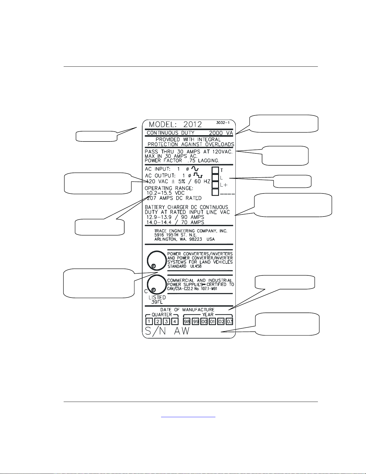
UNIT IDENTIFICATION
Model Number
Operating Range
Serial Number
The unit identification placard on the right side panel of the inverter/charger will show the serial
number, model number, listings, ratings, and date of manufacture.
Inverter Continuous Duty
Rating in Watts
Pass-Thru
Current Capacity
AC Input/Output Phase,
Waveform, Frequency and
DC Input Voltage
Testing Laboratory
Certification Number and
Standards Identification
U
U
Model Prefix
Charger Continuous Duty
Current Rating at DC
Bulk/Float Charging Rates
L
Date of Manufacture
L
Serial Number and
Product Code: AV=3012,
AW=2012, AX=2512
Trace Engineering Co. Inc. Tel (360) 435-8826 Part Number 3179
5916 195th Street, NE Fax (360) 435-2229 Effective August 6, 1998
Arlington, WA 98223 USA www.traceengineering.com Page
13
Page 22

Page 23
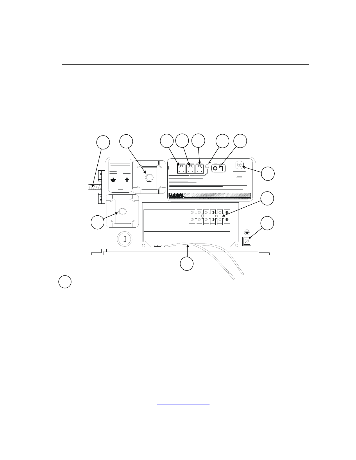
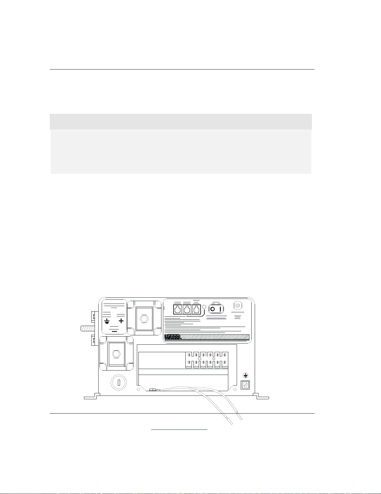
CONTROLS & INDICATORS
N
CAUTION
Controls & Indicators
The Legend Series II inverter/chargers feature a two-position On/Off rocker switch, tri-color status
indicator, battery temperature sensor (BTS) port, remote control port, and a charger circuit breaker
on the front panel.
4 3
7
6
5
2
1
12
11
8
10
9
1. On/Off Switch: Turns the inverter on or off.
ON: the inverter transforms 12-volt direct current from the batteries into 120-volt, 60 Hz alternating
current whenever AC current is not present at the AC Input Hot 1 terminal.
When 120-volt AC is present at the AC Input Hot 1 terminal, the inverter will pass the current through
to any AC loads connected to the inverter, and the standby battery charger will charge the batteries.
OFF: the inverter will not create AC power from the batteries, but will pass through AC current when
it is present at the AC Input Hot 1 terminal. The standby battery charger will charge the batteries
regardless of the position of the On/Off switch.
Trace Engineering Co. Inc. Tel (360) 435-8826 Part Number 3179
5916 195th Street, NE Fax (360) 435-2229 Effective August 6, 1998
Arlington, WA 98223 USA www.traceengineering.com Page
15
Page 24

CONTROLS & INDICATORS
NOTE:
The three-stage standby battery charger is always “On”. Whenever AC power is
present at the AC Input Hot 1 terminal, the charger will charge the batteries
connected to the battery positive and battery negative terminals. The On/Off
switch has no effect upon the charger.
2. LED Indicator
All Legend Series II inverter/chargers feature a tri-color LED on the front panel that will light green,
orange, or red to indicate the operating mode, battery or charger status, or an error condition.
Green:
Solid: inverter is providing AC power from the batteries
Slow Flashing: (once each second) inverter is in search mode
Fast Flashing: (four times each second) charger is charging in Float mode at 13.5 volts,
the factory setting for gel cell batteries. Float mode for liquid lead-acid batteries is 13.4 volts,
configured using the RC7 remote control. See the Three-Stage Battery Charger section on
Page 52 for a complete description of three-stage battery charging, and on Page 62, The
RC7 Remote Control section.
Orange
Solid: charger is in Bulk mode, the initial charging mode. Bulk mode for gel cell batteries is
set at the factory at 14.1 volts. Bulk mode voltage for liquid lead-acid batteries is set at 14.5
volts. Use the RC7 remote control to configure the inverter for liquid lead-acid batteries.
Flashing: charger is in Absorption charge. In Absorption stage, the charger maintains the
Bulk voltage at up to the maximum charge rate for 90 minutes.
Red
Solid: an over-current event has occurred. An over-current condition is caused by too
many loads on the unit (excessive current demand). When this occurs, the inverter/charger
instantaneously detaches from the loads. If, after a ten-second delay, the current demand
on the unit is not excessive, the unit will automatically resume inverting. If the current
demand remains excessive, the unit will shut itself off and must be manually restarted by
turning the unit Off, then On again.
Trace Engineering Co. Inc. Tel (360) 435-8826 Part Number 3179
5916 195th Street, NE Fax (360) 435-2229 Effective August 6, 1998
Arlington, WA 98223 USA www.traceengineering.com
Page
16
Page 25

CONTROLS & INDICATORS
Flashing: (followed by a five-second pause) an error condition has occurred
Once = battery voltage is below Low Battery Cut-Out factory setting of 11.1 volts
(see Protection Circuitry section on Page 7 for a description of LBCO). The inverter
will automatically restart when battery voltage rises to 12.5 volts.
Twice = battery voltage is over 15.6 volts and inverter has shut down (see Page 7).
The inverter will automatically resume operating when battery voltage has dropped
below 15.6 volts.
Three = inverter is overheating and has shut off to protect itself. Reduce loads or
provide adequate ventilation. The inverter will automatically restart when cool.
Four = a charger fault has occurred. Return unit to an authorized Trace Service
Center for servicing.
Five or more: Not used with the Legend Series inverter/chargers.
3. BTS Port: An optional battery temperature sensor (BTS) can be plugged in at the RJ-11 four-
conductor connector. The BTS provides information that enables the three-stage standby
battery charger to “fine tune” the battery charge rates for better charging performance, greater
efficiency and longer life.
4. Stacking Port (not used). The Series II model is not a stackable unit.
5. Remote Control Port: The Legend Series II can be controlled up to 50 feet from the unit by
plugging in a remote control (RC6 or RC7). See the Options section for a complete description
of the RC6 and RC7 remote controls.
• The RC6 reports DC voltage, charging or inverter current, and turns the inverter on and off..
• The RC7 is a full function, programmable remote control with backlit LCD, battery capacity
and other meters.
6. Battery Positive Terminal
7. Vehicle Chassis Ground Terminal
8. Battery Negative Terminal
9. AC Safety Ground
10. External Chassis (equipment) Ground
11. AC Terminal Block
Trace Engineering Co. Inc. Tel (360) 435-8826 Part Number 3179
5916 195th Street, NE Fax (360) 435-2229 Effective August 6, 1998
Arlington, WA 98223 USA www.traceengineering.com Page
17
Page 26

CONTROLS & INDICATORS
12. Charger Circuit Breaker: 25 amps in the L2012 and L2512, 30 amps in the L3012. Press
breaker to reset.
Trace Engineering Co. Inc. Tel (360) 435-8826 Part Number 3179
5916 195th Street, NE Fax (360) 435-2229 Effective August 6, 1998
Arlington, WA 98223 USA www.traceengineering.com
Page
18
Page 27

QUICK INSTALL
Quick Install
Experienced installers, licensed electrical contractors, and knowledgeable laymen may follow the
installation overview in this section. All others are urged to read the entire Installation section before
installing the inverter/charger.
1. Unpacking – Before beginning, unpack the inverter/charger,
record the serial number on the inside cover of this booklet
and on the warranty card. Retain packing materials for
future use. Ensure that all components listed on the
Packaging Materials sheet are included. If any
components are missing, please call Customer
Service at (360) 435-8826.
2. Mounting – Mount the unit securely in a horizontal
position in a clean, dry, ventilated enclosure. Do
not mount the unit in the same enclosure as vented
or maintenance-free type vented batteries. Bolt the
unit down securely. Allow adequate clearance to allow
access to the front panel.
3. DC Cabling
• Ensure that the On/Off switch on the front panel of the inverter is in the Off position before you
begin the installation.
• Connect a cable from the positive terminal of the battery or battery bank to the battery positive
(red) terminal of the inverter. See Minimum Recommended Battery Cable Size (In free air) in
Appendix C to determine the proper size cable to use for the inverter model and length of run
needed for your specific application. The National Electric Code (NEC) requires the use of a DC
fuse or disconnects in this cable within 18-inches of the batteries. See Appendix C to determine
the correct size fuse or breaker to use.
• Connect an appropriate sized cable from the battery’s negative terminal to the negative (black)
terminal on the inverter. Torque all terminals to 12 foot-pounds.
• Connect a cable from the Vehicle Chassis Ground (green terminal) on the inverter to chassis
ground (usually the frame of the vehicle).
4. DC Loads
• Connect a cable from the positive battery terminal to the positive buss of your DC load center.
• Ground all of your DC loads to your vehicle’s chassis, or connect a cable from the ground bus of
the DC load center to the vehicle chassis.
Trace Engineering Co. Inc. Tel (360) 435-8826 Part Number 3179
5916 195th Street, NE Fax (360) 435-2229 Effective August 6, 1998
Arlington, WA 98223 USA www.traceengineering.com Page
19
Page 28
QUICK INSTALL
N
CAUTION
5. AC In Cabling
• See Recommended Minimum AC Wire Sizes in Appendix C to determine the appropriate AC
wire size.
! Caution:
This inverter/charger includes neutral to ground switching for the AC electrical
system. The AC system in mobile installations must have the neutral physically
isolated from the ground throughout the load distribution powered by the
inverter.
• Disconnect any and all sources of AC power from the vehicle.
• Remove the knockout from the front or either side of the inverter chassis and install a strain relief
or conduit in which to route the AC cabling in and out.
• Connect the black wire from an appropriately sized three-conductor AC cable from the hot side
of the AC power supply (shore power connector) to the terminal labeled “AC Input Hot 1” on the
inverter.
• Connect the white wire from the neutral side of the AC power source to the terminal labeled “AC
Input Neutral” on the inverter.
• Connect the green wire from the ground of the AC power source to one of the two green wires
(AC Safety Ground) bolted to the chassis of the inverter/charger.
Trace Engineering Co. Inc. Tel (360) 435-8826 Part Number 3179
5916 195th Street, NE Fax (360) 435-2229 Effective August 6, 1998
Arlington, WA 98223 USA www.traceengineering.com
Page
20
Page 29

QUICK INSTALL
6. AC Out Cabling
• Connect the black wire of a three-conductor AC cable between the terminal marked “AC Output
Hot 1” to the hot bus of your AC load center or AC sub-panel.
• Connect the white wire from the terminal marked “AC Output Neutral” to the neutral bus of your
AC load center or sub-panel.
• Connect the remaining green wire bolted to the chassis of the inverter to the safety ground bus of
the AC load center or sub-panel.
7. Wrap up
• Secure all wiring with wire ties or other non-conductive fasteners to prevent chafing or damage
from movement and vibration. Use strain relief’s, grommets, or conduit to prevent damage to the
wiring where it passes through bulkheads or any apertures. Tighten all connections to 10-15 foot
pounds.
• Check to see that the inverter front panel switch is in the “Off” position, then reconnect to the AC
power source.
• Turn the inverter to the “On” position and check inverter operation (See Operation section)
Trace Engineering Co. Inc. Tel (360) 435-8826 Part Number 3179
5916 195th Street, NE Fax (360) 435-2229 Effective August 6, 1998
Arlington, WA 98223 USA www.traceengineering.com Page
21
Page 30

Page 31

INSTALLATION
Installation
In this portion of the manual, we will look at requirements and recommendations for installing a
Legend Series II inverter/charger. Keep in mind that these are only guidelines. Common sense, the
National Electrical Code and local building codes are the final authority.
Locating the Inverter
Inverters are sophisticated electronic devices and should be treated accordingly. When selecting the
operating environment for the inverter, don’t think of it in the same terms as other equipment it works
with, e.g. batteries, diesel generators, gas generators, washing machines etc. It is a highly complex
microprocessor controlled device. Generically speaking, it is a cousin to stereo equipment, television
sets, and computers. The use of conformal-coated circuit boards, plated copper bus bars, powder
coated metal components, and stainless steel fasteners improves tolerance to hostile environments.
However, in a condensing environment (one in which humidity and temperature change cause water
to condense on components) all the ingredients for electrolysis are present — water, electricity, and
dissimilar metals. In a condensing environment, the life expectancy of the inverter is indeterminate
and the warranty is voided.
! Caution:
It is in your best interests to install the inverter in a dry, protected location away
from sources of high temperature and moisture. Exposure to saltwater is
particularly destructive, potentially hazardous, and not covered by warranty.
Locate the inverter as close to the batteries as possible in order to keep the battery cable length
short. However, do not locate the inverter in the same compartment as vented batteries. Batteries
generate hydrogen sulfide gas, which is very corrosive to electronic equipment and everything else.
They also generate hydrogen and oxygen. If accumulated, this mixture will ignite by an arc caused
by the connecting of battery cables or the switching of a relay. Mounting the inverter in a ventilated
enclosure with sealed batteries is acceptable.
Ventilation
Installation of the inverter in a properly ventilated enclosure is mandatory for proper operation of the
unit. Installation in an enclosure that is too tight or poorly ventilated will result in lower peak power
output, reduced surge capability, and potentially shorter inverter life. This is due to the inverter
reaching its thermal shutdown point sooner than normal from lack of ventilation.
Trace Engineering Co. Inc. Tel (360) 435-8826 Part Number 3179
5916 195th Street, NE Fax (360) 435-2229 Effective August 6, 1998
Arlington, WA 98223 USA www.traceengineering.com Page
23
Page 32

INSTALLATION
4kw
Power
3kw
Output
2kw
1kw
0 10 20 30 40 50 60 70 80 90 100
Ambient Temperature in °Celsius
Figure 1, Power Output Versus Temperature
Figure 1, Power Output Versus Temperature is for the L3012. It outlines the ambient temperature
needed in order for the inverter to perform to its published specifications.
The chart shows the output capabilities of the inverter, which is dependent on the ambient
temperature in the enclosure where the inverter is located. The dark line represents the maximum
power that may be expected from the inverter for a given ambient temperature. Testing has shown
that the volume of the enclosure is not as important as the overall ventilation. As long as a minimum
airspace of 1 ½ - inches is maintained around the sides of the inverter, and three inches at the back of
the inverter with the cooling fan, adequate ventilation should be maintained. Because the top of a
Legend Series II inverter is not vented, clearance between the enclosure and the top of the inverter is
not relevant.
The fan at the end of the inverter enclosure is for cooling. This fan pressurizes the inverter and
ventilates through the side vents of the unit. A fresh air intake opening should be provided directly to
the fan if possible, and an exhaust port directly opposite that will allow cool outside air to flow through
the inverter and back out of the enclosure.
Mounting
UL specification 458 (land vehicle installations) requires that the inverter be mounted on a flat
surface. The purpose of this requirement is to orient the inverter so that its bottom cover has no
holes that would allow burning material to be ejected in the event of an internal fire.
Trace Engineering Co. Inc. Tel (360) 435-8826 Part Number 3179
5916 195th Street, NE Fax (360) 435-2229 Effective August 6, 1998
Arlington, WA 98223 USA www.traceengineering.com
Page
24
Page 33

INSTALLATION
DC Wiring
Safety Instructions
The inverter’s maximum peak current requirements and the charger’s output current capabilities are
high. If battery cables are too small and/or connections are loose, efficiency and maximum output
power are degraded. Small cables or loose connections can also cause dangerous overheating of
the wire and/or terminals.
Observe Battery Polarity! Place the battery cable ring terminals over the bolt and directly against
the inverter’s battery terminals. A 'snap' caused by arching may occur-this is normal. Red is positive
(+), Black is negative (-) Use a 1/2-inch wrench or socket to tighten the 5/16 SAE nut to 10-15
foot/pounds. Do not place anything between the flat part of the inverter terminal and the battery
cable ring terminal or overheating may occur. Do not apply any type of anti-oxidant paste to
terminals until after the battery cable wiring is tightened to 10–15 foot-pounds!
Caution!
This inverter is not reverse polarity protected! If the positive terminal of the
battery is connected to the negative terminal of the inverter the probable result
is failure of the unit. This type of failure is very obvious and is not covered
under warranty. Double check when making battery connections!
Use the largest gauge wire and the shortest possible length when choosing battery cables. Tape the
battery cables together every few inches with non-conductive electrician’s tape or nylon tie-wraps.
This reduces the inductance of the wire resulting in a better waveform and less current in the
inverter’s filter capacitors. This directly relates to output efficiency and inverter life span. High
inductance in battery cabling is like placing a spring into the system between the battery bank and
inverter. This spring absorbs, stores, and releases energy opposite to that flowing in the system. In
this way efficiency and electrical characteristics are degraded.
Note
Never disconnect the battery cables while the inverter is delivering power or
battery charger is operating. The On/Off switch has no effect upon the charger.
It turns Off only the inverter. To disconnect the batteries for service. a) turn off
the power switch, b) disconnect all AC power, c) disconnect the battery cables.
DC Cabling Connections
Color-code your battery cables with colored tape or heat shrink tubing. The standard is red for
positive (+) and black for negative (-).
Trace Engineering Co. Inc. Tel (360) 435-8826 Part Number 3179
5916 195th Street, NE Fax (360) 435-2229 Effective August 6, 1998
Arlington, WA 98223 USA www.traceengineering.com Page
25
Page 34

INSTALLATION
2/0 Aluminum Mechanical Lug
Cables must have crimped and/or soldered copper compression lugs unless aluminum mechanical
lugs are used. We suggest using high quality UL listed Trace Engineering battery cables. These
cables are available in a specific assortment of sizes from 1 ½ to 10 feet, and in 2/0 or 4/0 AWG.
They are color-coded and have pressure crimped, sealed ring terminals. Contact your Trace dealer
to order.
Do not place anything between
battery cable lug and terminal
surface. Assemble exactly as shown
2/0 Copper Compression Lug
Figure 2, Battery to Inverter Cable Connection
.
Figure 2, Battery to Inverter Cable Connection illustrates proper connections for the Legend Series II
inverter/chargers. Points of caution are:
ü Do not connect the battery negative (-) terminal to the vehicle chassis; connect it to the
battery negative terminal of the inverter.
ü Do not connect the DC load negatives to the battery negative (-), connect only to the
chassis ground terminal on the inverter or to the vehicle chassis.
These connections are necessary in order for the RC7 remote control fuel gauge to work properly.
All current into or out of the battery must pass through the internal shunt, which is between the
chassis ground and battery negative terminals.
Trace Engineering Co. Inc. Tel (360) 435-8826 Part Number 3179
5916 195th Street, NE Fax (360) 435-2229 Effective August 6, 1998
Arlington, WA 98223 USA www.traceengineering.com
Page
26
Page 35

INSTALLATION
Copper Compression Lugs: Commonly available at hardware, welding, and auto parts retailers,
compression lugs must be crimped onto each cable using an appropriate crimping tool. These lugs
are not available from Trace Engineering. Suggested sources and part numbers are:
Hollingsworth, Pompano Beach, FL305-979-2050
Part # Description
TL3061 2/0 Ring Terminal
TL3062 4/0 Ring Terminal
H40 8 AWG to 250MCM Air-Operated Crimping Tool
Thomas & Betts
K973 2/0 Ring Terminal
M973 4/0 Ring Terminal
RJ737 2/0 Insulated Ring Terminal
RL737 4/0 Insulated Ring Terminal
TBM6 Hand Operated Crimping Tool (order dies separately)
Dies: #11809 for crimping 2/0 non-insulated lugs
#11811 4/0 non-insulated lugs
#11826 2/0 insulated lugs
#11828 4/0 insulated lugs
Mechanical Lugs: Aluminum mechanical lugs are available from electrical hardware suppliers and
do not require crimping. Suggested sources and part numbers are:
Part # Description
ILSCO
TA-2/0 2/0 Lug
TA-250 (preferred) 250 MCM Lug
Thomas &Betts
62205 2/0 Lug
62212 250 MCM Lug
Panduit
LAMA2/0-14 2/0 Lug
LAMA250-56. 250 MCM Lug
Ground Cable Connection
You probably noticed that the Trace Legend Series II inverter/chargers have a third battery terminal
labeled “Vehicle Chassis Ground” (the green terminal on the left side of the unit). The purpose of this
third terminal is be sure that all DC load current into or out of the battery bank will flow through the
internal shunt of the inverter. The internal shunt is connected between the black battery negative
terminal and the green chassis ground terminal of the inverter (See Figure 3, DC Wiring Diagram on
Page 30.)
Because all DC loads in a vehicle are generally connected to a common chassis ground and not
directly to the battery negative (in a negative ground system), all DC current in the system will at
some point pass through the chassis and then into the battery bank. If the inverter is in this loop the
net current flow is easily monitored. Thus, the RC7 remote control’s battery fuel gauge feature is
Trace Engineering Co. Inc. Tel (360) 435-8826 Part Number 3179
5916 195th Street, NE Fax (360) 435-2229 Effective August 6, 1998
Arlington, WA 98223 USA www.traceengineering.com Page
27
Page 36

INSTALLATION
Model #
Amps
Fuse Size
One Way
One Way
One Way
possible. You may connect the system without going through the chassis ground terminal, but the
RC7’s fuel gauge feature will not work properly.
Battery Cable Sizing
The bigger the battery cables the better. Undersized cables result in additional stress on the inverter,
lower efficiency, reduced surge power and lower peak output voltage. Don’t use cables that are too
small in diameter. The following table gives recommended cable sizes for the various cable-run
lengths and inverter voltages.
Table 1, Minimum Recommended Battery Cable Size (In free air)
Inverter
Typical DC
Minimum
1 to 3 feet
3 to 5 ft
5 to 10 ft
L2012 200 Amps 250A 00 00 0000
L2512 250 Amps 300A 00 0000 0000
L3012 300 Amps 400A 0000 0000 0000
The term “Free Air” is defined by the NEC as the cabling not being enclosed in conduit or raceway.
Cables enclosed have a substantially lower continuous current carrying ability due to heating factors.
The National Electric Code (NEC) requires that the cables be protected by a fuse or breaker rated to
match the cables ampacity at 75 degrees Celsius. The NEC also allows rounding up to the next fuse
size from the cable rating, i.e. 150-amp cable size rounds up to a 175-amp fuse size.
Warning!
Under-sized cables may melt or burn if the inverter is asked to produce high
power.
DC Over Current Protection
In order to comply with the UL 458 safety standard (Land Vehicle Installations) a UL approved type of
battery over-current protection is required. Fuses and disconnects must be sized to protect the
wiring in the system. The fuse is required to blow before the wire reaches its maximum current
carrying capability.
These installation parts are not supplied as part of the inverter. However, Trace Engineering offers a
DC-rated class T fuse and safety-covered fuse block which are compatible with the Legend Series II
Trace Engineering Co. Inc. Tel (360) 435-8826 Part Number 3179
5916 195th Street, NE Fax (360) 435-2229 Effective August 6, 1998
Arlington, WA 98223 USA www.traceengineering.com
Page
28
Page 37

INSTALLATION
in Free Air
Fuse Size
inverter. The fuses are available in 110, 200, 300, and 400 amp sizes. Contact your Trace dealer to
order; see the Options section of this manual for more information.
Note
To order a fuse with fuse block from a Trace Dealer, order part number TFB
followed by the desired fuse size in amps (i.e. TFB 400). When ordering
replacement fuses, the part number is TF followed by the size in amps of the
desired fuse (i.e. TF400).
Table 2, Current Carrying Ability of Wire In Free Air at 75°C
Cable Size Maximum Rating
Maximum
# 2 AWG 170 amps 175 Amp
00 AWG 265 amps 300 Amp
0000 AWG
360 amps 400 Amp
Trace Engineering Co. Inc. Tel (360) 435-8826 Part Number 3179
5916 195th Street, NE Fax (360) 435-2229 Effective August 6, 1998
Arlington, WA 98223 USA www.traceengineering.com Page
29
Page 38

INSTALLATION
As an option, you may
DC Load
Fuse Block
Vehicle Chassis
Ground (green)
Internal Shunt
directly connect between
DC load center negative
and vehicle chassis
ground (green) terminal of
inverter
NOTE: In accordance with
NEC code, the fuse block
must be no more than 18
inches from the battery
bank.
Distribution
Panel
Out to DC loads
Figure 3, DC Wiring Diagram
Trace Engineering Co. Inc. Tel (360) 435-8826 Part Number 3179
5916 195th Street, NE Fax (360) 435-2229 Effective August 6, 1998
Arlington, WA 98223 USA www.traceengineering.com
Page
30
Page 39

INSTALLATION
AC IN NEUTRAL
AC OUT NEUTRAL
AC OUT HOT
AC Wiring
The National Electrical Code (NEC) defines the standards for AC installation wiring in vehicle
applications, but there are still many installation variables; most are determined by the level of
automatic switching desired and the amount of external AC power to be switched. A qualified
electrician should do the installation.
AC and DC Wiring Separation
Do not mix AC and DC wiring in the same conduit. A separate conduit should be used for each.
Induced current in the DC conductors could cause confusion with the inverter’s microprocessor.
Where DC wiring must cross AC or vice-versa, make the wires at the crossing point 90° to one
another. Consult code for details of DC and AC wiring in vicinity to one another.
AC Wire Connections
The AC and DC terminals are located on the front panel of the chassis. A six-station terminal block is
provided to make the AC connections. The terminal block is used to hardwire the AC input and AC
output. All terminals are labeled on the inverter. Consult your local code for proper wire sizes,
connectors, conduit, etc. Table 2, "Current Carrying Ability of Wire in Free Air" gives suggestions for
wire sizing. Code requires that an external disconnect switch be used in the AC input wiring circuit.
The AC breakers in a sub panel will meet this requirement.
NOT USED
NOT USED
AC IN HOT
Figure 4, AC Terminal Block
When installing an inverter in a vehicle, do not use solid wires such as Romex because of the
potential for shortened wire life due to vibration-induced breakage. Stranded copper wire is required.
As a plus, stranded wire is generally much more flexible and thus easier to work with.
Trace Engineering Co. Inc. Tel (360) 435-8826 Part Number 3179
5916 195th Street, NE Fax (360) 435-2229 Effective August 6, 1998
Arlington, WA 98223 USA www.traceengineering.com Page
31
Page 40

INSTALLATION
SCREW ONCHASSISBLACKHOT 1AC INWHITENEUTRALAC INGREENGROUNDSAFET
Y
2030203
0
PN2370 REV
A
LIGHTSPLUGS
INVERTER/CHARGE
R
IRCUI
TBREAKE
R
CHARGET
O
NONCN
O
RCUIT
NCNON
C
60A
HOT 1AC OUTBLAC
K
FRIG.
151
5
SUB PANEL120VACLOADS ONLY30 AMPSNEUTRALAC OUT
BLENDERTV
WHITE
1515151
5
TYPICAL 120/240VAC 3 WIRE ELECTRICAL SYSTEM DIAGRAM
30 AMP OPERATION:
C HOT IN TO AC HOT IN 1
C HOT OUT TO AC HOT OUT 1TYPICAL INVERTER LOADS
The following steps are a basic guideline for installation and connection of the AC wiring into and out
of the inverter.
1. Disconnect the inverter from the battery bank (if already connected), by either removing the DC
side fuse, or opening the DC disconnect. Then remove the AC wiring compartment cover from
the front of the inverter by removing the two screws at the bottom of the cover.
2. If conduit will be utilized (consult code, it may be required in your installation), determine which
knockout(s) will be utilized and remove them from the inverter. Using appropriate conduit
connectors, fasten the conduit to the inverter. Feed all AC wiring through the conduit and into
the inverter AC terminal block (located on the front of the inverter). Be sure to leave yourself
several extra inches of wire to work with. Remember that you need at least two sets of three
conductor wiring, one for AC Hot, neutral, and ground into the inverter, and another for AC hot,
neutral and ground out of the inverter to the loads. Torque all AC terminals to 10 to 15 inchpounds.
3. Following the wiring guide shown below, connect the hot (black) and neutral (white) wires from
the AC source (shore power or generator set) to the appropriately labeled terminals in the AC
terminal block. The safety ground (green) should be connected to the terminal stud labeled
“ground” bolted to the floor of the chassis. Repeat the procedure for the AC wiring going to the
AC sub-panel which will power the loads, except connect these wires to the terminals labeled AC
hot out.
GENERATOR
120VAC OR
120/240VAC
120/240VAC
FOR 120VAC
CONNECT A
CONNECT A
50 AMP
SHORE
SERVICE
HOT
HOT
NEUTRAL
GROUND
EXTERNAL
TRANSFER
RELAY
SWITCH
240VAC
AIR
CONDITIONER
MAIN PANEL
120/240VAC
50 AMP
C
CI
Figure 5, AC Wiring Diagram
Trace Engineering Co. Inc. Tel (360) 435-8826 Part Number 3179
5916 195th Street, NE Fax (360) 435-2229 Effective August 6, 1998
Arlington, WA 98223 USA www.traceengineering.com
Page
32
Page 41

INSTALLATION
4. Inspect all wiring for proper installation and then replace the cover using the two 6/32nds screws
and lock washers to secure it.
Table 3, Recommended Minimum AC Wire Sizes
Inverter Model 120 VAC Input 120 VAC Output
L2012 10 gauge 12 gauge
L2512 8 gauge 10 gauge
L3012 8 gauge 10 gauge
! Important Precaution
The output side of the inverter’s AC wiring should at no time be connected to
public power or a generator. This condition is far worse than a short circuit. If
the unit survives this condition, it will shut down until corrections are made.
AC output must be isolated from ground to comply with the NEC requirement for neutral-ground
switching. This is easiest to do at the sub-panel by isolating the neutral connector block from
the frame of the subpanel with an appropriate insulator.
Ground Fault Interrupting Outlets (GFCI’s)
Trace Engineering has tested the following GFCI’s and found them to work satisfactorily with our
inverters:
LEVITON 6599
PASS & SEYMOR 1591RI 4A957
ACE Hardware ACE 33238
Some GFCI’s will nuisance trip when used with a modified square wave inverter. Trial is the only
way to tell for sure. On the above listed types, continued nuisance tripping is usually a result of a
wiring problem in the inverter AC output system. Leakage currents present somewhere in the AC
system are causing the GFCI to trip. Make a careful review of the AC wiring layout in your system
and look for possible unwanted ground paths. An error in wiring of the neutral-ground switching
system is a good place to start troubleshooting. Be sure that the AC output neutral is isolated from
the ground. A multimeter may be handy in this troubleshooting procedure.
Trace Engineering Co. Inc. Tel (360) 435-8826 Part Number 3179
5916 195th Street, NE Fax (360) 435-2229 Effective August 6, 1998
Arlington, WA 98223 USA www.traceengineering.com Page
33
Page 42

INSTALLATION
AC Source Selector Switch –
AC Main Panel
120 Volts AC, 60Hz
Shore
Power
Generator
Water Heater
Lights
Inverter AC
To Inverter
Vehicle Chassis
House Battery
Vehicle Starting
Vehicle
Ground
Automatic or Manual
Electric Range
Air Conditioner
AC Hot IN
Microwave
Refrigerator
TV/VCR
Outlets
Fuse Block
Sub-panel
Battery Isolator
Alternator
Bank
Battery
Figure 6, Typical Mobile Installation Diagram
Trace Engineering Co. Inc. Tel (360) 435-8826 Part Number 3179
5916 195th Street, NE Fax (360) 435-2229 Effective August 6, 1998
Arlington, WA 98223 USA www.traceengineering.com
Page
34
Page 43

INSTALLATION
RY-A
RY-B
(Inverter loads)
N
E
U
GND
Neutral-to-Ground Switching
All of the Legend Series units employ neutral to ground switching as required by the NEC (National
Electric Code). The purpose for this requirement is to ensure that the neutral conductor in a threewire system is "bonded" or connected to ground at only one point. This prevents a voltage
difference from developing between the vehicle's neutral and the AC source's neutral, which may
cause an electric shock. When the unit is operating as an inverter, the AC output neutral is connected
to the chassis ground by an internal relay, creating the bond within the inverter. When operating from
an external AC power source the internal relay in the inverter opens and removes the ground from
the neutral conductor and allows the "bond" to be provided by the external AC source.
The diagram below graphically describes the ground switching system in the inverter for a unit
operating as an inverter and feeding the AC sub-panel.
Relay RY-A connects the
inverter out to the AC
HOT output.
Inverter
AC
out
Relay RY-B connects the NEUTRAL (OUT) to chassis or vehicle
ground when AC power is not present at the inverter input. This
assures all equipment in the vehicle is referenced to the same ground.
Neutral-to-Ground “BOND” is provided by the
internal relay for entire AC system
HOT OUT
NEUTRAL OUT
AC Sub-panel
The
neutral
conductor
shall be
insulated
from the
equipment
grounding
conductors
or
enclosures
Figure 7, Neutral-to-Ground Switching without external AC source
Trace Engineering Co. Inc. Tel (360) 435-8826 Part Number 3179
5916 195th Street, NE Fax (360) 435-2229 Effective August 6, 1998
Arlington, WA 98223 USA www.traceengineering.com Page
35
Page 44

INSTALLATION
RY-A
RY-B
(Inverter loads)
N
E
U
GND
For this system to work, the AC output neutral of the inverter must be isolated from the ground of the
system (usually the green wire). When in the inverter mode, the neutral ground switching relay will
automatically connect (bond) the output neutral to ground, and when in charger/pass-through mode,
the ground and neutrals will be bonded to one another at the AC source (generator or shore power).
The diagram below graphically describes the ground switching system in the inverter for a unit
connected to an external AC source (generator, grid etc.) and passing the AC power through the
inverter to the AC sub-panel.
Relay RY-A connects the AC input and
AC output HOT sides together to allow
power to pass through the inverter when
AC is present at the inverter inputs.
Inverter
AC
out
GROUND
HOT IN
NEUTRAL IN
HOT
NEUTRAL
GROUND
Neutral-to-Ground “BOND” is provided by the
external AC source for entire AC system
Relay RY-B connects the NEUTRAL (IN)
from the external AC source and NEUTRAL
(OUT) of the loads together when AC is
applied to the inverter.
HOT OUT
NEUTRAL OUT
AC Sub-panel
The
neutral
conductor
shall be
insulated
from the
equipment
grounding
conductors
or
enclosures
Figure 8, Neutral-to-Ground Switching with External AC
Trace Engineering Co. Inc. Tel (360) 435-8826 Part Number 3179
5916 195th Street, NE Fax (360) 435-2229 Effective August 6, 1998
Arlington, WA 98223 USA www.traceengineering.com
Page
36
Page 45

INSTALLATION
Cut
the green wire here
on mobile units only)
If no neutral to ground switching were employed in an inverter there would be one neutral tied to the
AC sub-panel and the other neutral to the vehicle or chassis ground. The two different ground points
would now form a current carrying conductor with the vehicle chassis acting as the “wire” between
the two different ground points. This means any ground point in the vehicle becomes a potential
current careering conductor, which could result in electrical shock. This ground loop could also be a
cause for nuisance tripping of any GFCI’s (Ground Fault Circuit Interrupter).
Disabling Neutral Ground Switching
Legend inverters employ neutral-to-ground switching. In countries such as Canada this may be
utilized, and therefore may need to be disabled before installation. Check local code if you are not
sure whether you must disable the neutral ground switching feature.
Note: Connect the chassis ground to the vehicle chassis even if ground switching has been disabled.
Disabling the ground switching is very simple if precautions are taken and these steps followed:
1. If the inverter is already installed, disconnect any AC sources (If any are present)
2. Disconnect the battery(s) from the inverter.
3. Remove the AC terminal block cover on the front of the inverter.
4. Locate the green wire that runs from the circuit board to the chassis ground bolt as shown
in the figure below. Cut this wire and wrap the cut end with insulating tape.
Chassis ground bolt
(Neutral to Ground Wire
Figure 9, Disabling Neutral-to-Ground Switching
Trace Engineering Co. Inc. Tel (360) 435-8826 Part Number 3179
5916 195th Street, NE Fax (360) 435-2229 Effective August 6, 1998
Arlington, WA 98223 USA www.traceengineering.com Page
37
Page 46

OPERATION
5. Do not cut the green wire that goes from the connector block to the chassis.
6. Replace the AC terminal block cover and reconnect the battery(s) and the AC sources.
Operation
Once the AC and DC wiring have been installed and connected, take a moment to go back
over all connections and make sure they are secure and in the proper terminal(s).
Important! Before proceeding…
If the system utilizes liquid lead-acid type batteries instead of sealed gel-cell
type, you will need to use the RC7 remote control to change the set-up for
battery type from gel-cell to liquid lead-acid. If you don’t know which battery
type you have, use the gel-cell setting just to be safe, and then contact the
battery manufacturer.
1. Check to see that the inverter is turned off, then apply battery (DC) power to it. Ensure that all
wiring has been installed properly. Next, turn on the battery bank DC disconnect or connect the
proper fuse inline to the battery to complete the battery circuit. When done, the inverter will go
through a start-up self test. This will include the fan running, and relays opening and closing.
If the inverter does not come on or go through the start-up self test, check all connections.
Check the inverter’s DC voltage on the positive (+) and negative (–) terminals. If the DC voltage
is low or if the battery bank needs to be charged, skip Step Two and go directly to Step Three.
2. Turn the inverter power switch to the “On” ( | ) position. The inverter should run a load with no
AC connected (battery only). Place a load on the inverter (plug in a light or other load to an outlet
the inverter is powering), and make sure it works.
3. Apply shore power. The charger should charge the battery bank. To charge your batteries,
connect shore power to the inverter by plugging in the shore power cord and turning on the
shore power breaker. After a minimum 20 seconds delay, the light on the front of the inverter
should indicate it is in one of the three charge stages (bulk, absorption, or float). This indicates
the charger is working properly. If you have an RC6 or RC7 remote control, it should indicate
which charge stage the inverter is currently in. Any AC loads powered by the inverter should
also work at this point since a portion of the shore power is passed through the inverter to power
the loads. The delay before connecting is provided while the inverter is “sampling” the shore
power to see that it is within acceptable frequency and voltage limits. This delay also allows time
for a generator to spin up to a stable operating condition before connecting to the inverter. In this
manner relay chatter is reduced.
Trace Engineering Co. Inc. Tel (360) 435-8826 Part Number 3179
5916 195th Street, NE Fax (360) 435-2229 Effective August 6, 1998
Arlington, WA 98223 USA www.traceengineering.com
Page
38
Page 47

OPERATION
4. Disconnect shore power. Take away the shore power by turning the shore power breaker off, or
unplugging the shore power. The inverter should transfer to inverter mode immediately. This will
be indicated by a clicking sound as the internal transfer relays change position. The inverter will
begin to “buzz” as it takes power from the batteries and uses it to power the loads. The loads
should continue to operate uninterrupted.
The above steps will complete a functional test of the inverter. If all areas pass, the inverter is ready
for use. If any area fails, figure out why before proceeding. The troubleshooting guide in Appendix
A: Troubleshooting will help you solve problems you encounter. If any of the inverter’s internal
setpoints are to be adjusted, consult the booklet included with the RC7 remote control.
Trace Engineering Co. Inc. Tel (360) 435-8826 Part Number 3179
5916 195th Street, NE Fax (360) 435-2229 Effective August 6, 1998
Arlington, WA 98223 USA www.traceengineering.com Page
39
Page 48

Page 49

BATTERIES
Batteries
This section of the manual is included to help you better understand the factors involved with battery
charging, care, and maintenance, by discussing the physical make-up and characteristics of
chemical storage batteries. This is not intended to be an exhaustive discussion of battery types, but
simply a guideline. The manufacturer of each specific battery is the best authority as to its use and
care.
Batteries come in different sizes, types, amp-hours, voltages and chemistries. It is not possible here
to discuss all aspects in detail. However, there are basic guidelines you can follow that will help in
battery selection and ensure that your batteries are better maintained than the majority.
Terminology
A description of battery charger operation requires the use of terms with which you may not be
familiar. The following terms appear in the description of batteries and battery charger operation.
ü Electrolyte: Typically a mixture of water and sulfuric acid, it is commonly referred to as
battery acid.
ü Plates: Originally made of lead, now fabricated from lead oxide. Plates connect to the
battery terminals and provide a structure for the chemicals that create current. There are
several plates in each cell, each insulated from the other by separators.
ü Sulfating: As a battery discharges, its plates become covered with lead sulfate. During
recharging, the lead sulfate leaves the plates and recombines with the electrolyte. If the lead
sulfate remains on the plates for an extended period of time (over two months), it hardens,
and recharging will not remove it. This reduces the effective plate area and the battery’s
capacity.
ü Stratification: Over time, a battery’s electrolyte (liquid) tends to separate. The electrolyte at
the top of the battery becomes watery while at the bottom it becomes more acidic. This
effect is corrosive to the plates.
ü Deep Cycle: A deep cycle occurs when a battery is discharged to less than 20% of its
capacity (80% depth-of-discharge).
ü Temperature Compensation: Peak available battery voltage is temperature dependent.
As ambient temperatures fall, the proper voltage for each charge stage needs to be
increased. An optional temperature-probe (BTS) automatically re-scales charge-voltage
settings to compensate for ambient temperatures. The compensation slope based on cell
voltage is -2.17mv per degree Fahrenheit per cell (30mv per degree Celsius) for lead-acid
batteries.
Trace Engineering Co. Inc. Tel (360) 435-8826 Part Number 3179
5916 195th Street, NE Fax (360) 435-2229 Effective August 6, 1998
Arlington, WA 98223 USA www.traceengineering.com Page
41
Page 50

BATTERIES
Types
There are two principal types of batteries: starting and deep-cycle. There are several different types
of battery chemistries including liquid lead-acid, nickel-iron (NiFe), nickel-cadmium (NiCad), alkaline,
and gel-cell. Batteries are either sealed or vented.
Starting Batteries
Starting batteries are designed for high cranking power, but not deep cycling. Do not use them with
your inverter. They do not hurt the inverter but they simply will not last long in a deep-cycle
application. The way they are rated should give a good indication of their intended use: “Cold
Cranking Amps”, a measure of the amperage output that can be sustained for 30 seconds. Starting
batteries use lots of thin plates to maximize the surface area of the battery. This allows very high
starting current but lets the plates warp when the battery is cycled.
Deep-Cycle Batteries
Deep-cycle batteries are best suited for use with inverters. They are designed to have the majority of
their capacity used before being recharged. Available in many sizes and types, the most common
type is the non-sealed, liquid electrolyte battery. Non-sealed types have battery caps. The caps
should be removed at least monthly to check the level of electrolyte. When a cell is low, only distilled
water should be added. The electrolyte level should be checked monthly and topped up if needed
after recharging.
The most common deep-cycle batteries are the types used with boats and motor homes. They are
12-volt batteries rated at 80 to 100 amp-hours. Often the deep cycle claim is over-stated. They do
have greater capacity than a car battery, but are not recommended.
Another popular and inexpensive battery of this type is the “golf car” (T-105 or CG220) battery.
Rated at 220 amp-hours, these six-volt batteries can be discharged repeatedly to 80% of their
capacity without being damaged. This is the minimum quality of battery that should be used with the
Legend Series II inverter in normal applications.
Some systems use the L16 type of battery. These are 6-volt batteries rated at 350 amp-hours and
are available from a number of manufacturers. They are 17 inches in height and weigh up to 130
pounds each - which may be troublesome in installations.
Type 8D batteries are available in either cranking or deep-cycle construction. The deep cycle
versions are 12-volt batteries rated at 200 amp-hours or so. Since they are most commonly used to
start truck engines, you should make sure you purchase the deep cycle version. Type 4D batteries
are very similar in construction, but somewhat smaller.
Sealed Gel Cell
Another type of battery construction is the sealed gel-cell. They don’t use battery caps. The
electrolyte is in the form of a gel rather than a liquid. This allows the batteries to be mounted in any
position without spilling. The advantages are no maintenance (to the battery itself, the system will still
Trace Engineering Co. Inc. Tel (360) 435-8826 Part Number 3179
5916 195th Street, NE Fax (360) 435-2229 Effective August 6, 1998
Arlington, WA 98223 USA www.traceengineering.com
Page
42
Page 51

BATTERIES
require routine maintenance), long life (800 cycles claimed) and low self-discharge. The
disadvantage is high initial cost and the possibility of damage from overcharging.
While there are many manufacturers of quality non-sealed batteries, there are only a few
manufacturers of suitable gel-cells. Don’t confuse sealed batteries with maintenance free batteries.
The latter is typically a standard liquid electrolyte type battery without caps for adding water, and
when the electrolyte gets low, you replace the battery.
AGM (absorbed glass mat) batteries are similar to gel-cells and may be used in inverter applications.
Environment
For long life and good performance, batteries need to be located in protected enclosures insulated
from extremes in temperature. These environmental factors are discussed in the following sections.
Location
Batteries should be located in an accessible location with access to the battery caps and terminals.
At least six inches of clearance above is recommended. They must be located as close as possible
to the inverter, but can not limit the access to the inverter and the inverter’s over-current protection
device.
The over-current protection device must be located per code within 18 inches of the battery
installation, and must be covered to prevent possibility of discharging material in the event of a short
circuit.
Enclosures
Batteries must be protected inside a ventilated enclosure. The enclosure should be ventilated to the
outdoors from the highest point to prevent accumulation of hydrogen gasses released in the charging
process. An air intake should also be provided at a low point in the enclosure to allow air to enter the
enclosure to promote good ventilation. For most systems, a one-inch diameter vent pipe from the top
of the enclosure is adequate to prevent accumulation of hydrogen.
Temperature
The effective capacity of a battery is reduced when cold. This phenomenon is more significant with
lead-acid type batteries compared to alkaline types. When the internal temperature of a lead-acid
battery is 32°F (0 °C) the capacity can be reduced by as much as 50%. This effectively reduces the
size of the system’s “gas tank”, requiring more frequent “refueling” by the back-up source (usually a
generator). This should be considered when designing the system. If extremely cold temperatures
are expected at the location of a system, either a heated equipment room or alkaline batteries should
be considered.
If the system is located in an unheated space, an insulated enclosure is highly recommended for the
batteries. During the charging process, the batteries release heat due to the internal resistance of
Trace Engineering Co. Inc. Tel (360) 435-8826 Part Number 3179
5916 195th Street, NE Fax (360) 435-2229 Effective August 6, 1998
Arlington, WA 98223 USA www.traceengineering.com Page
43
Page 52

BATTERIES
the battery. If the batteries are insulated, the heat can be kept in the batteries to keep them warmer.
This will substantially increase the performance of the system.
Insulated battery enclosures also ensure that the temperatures of the individual battery cells are
more consistent, preventing unequal charging which can cause battery failure (some cells will be
overcharged while others are undercharged).
The batteries should also be protected from high temperature as well. This can be caused by high
ambient temperatures, solar heating of the battery enclosure, or heat released by a closely located
generator. High battery temperatures will result in short battery life and should be avoided by
ventilating the enclosure and reducing the external heat sources by shading and insulation.
Battery Bank Sizing
Batteries are the inverter’s fuel tank. The greater amp-hour capacity of the batteries, the longer the
inverter can operate before recharging is necessary. An undersized battery bank results in reduced
battery life and disappointing system performance.
Batteries should not be discharged more than 50% of their capacity on a regular basis. Under
extreme conditions cycling to a discharge level of 80% is acceptable. Totally discharging a battery
may result in permanent damage and reduced life.
Estimating Battery Requirements
In order to determine the proper battery bank size, it is necessary to compute the number of amphours that will be used between charging cycles. When the required amp-hours are known, size the
batteries at approximately twice this amount. Doubling the expected amp-hour usage ensures that
the batteries will not be overly discharged and extends battery life. To compute total amp-hours
usage, the amp-hour requirements of each appliance that is to be used are determined and then
added together.
You can compute your battery requirements using the nameplate rating of your appliances. The
critical formula is WATTS = VOLTS X AMPS . Divide the wattage of your load by the battery voltage
to determine the amperage the load will draw from the batteries. If the AC current is known, then the
battery amperage will be:
(AC volts X AC current) / Battery Bank Voltage X 1.2 (efficiency loss) = DC amps (Battery amps)
Multiply the amperage a load requires by the number of hours the load will operate and you have,
reasonably enough, amp-hours.
Motors are normally marked with their running current rather than their starting current. Starting
current may be three to six times running current. Manufacturer literature may provide more
accurate information compared to the motor nameplate. If large motors will be started, increase the
battery size to allow for the high demand start-ups require.
Trace Engineering Co. Inc. Tel (360) 435-8826 Part Number 3179
5916 195th Street, NE Fax (360) 435-2229 Effective August 6, 1998
Arlington, WA 98223 USA www.traceengineering.com
Page
44
Page 53

BATTERIES
Battery Bank Sizing Example & Worksheet
Complete the steps that follow to calculate your battery bank capacity. No two installation will require
exactly the same battery bank capacity. The example that follows will provide a guideline for
determining your needs. Read through the example and then complete the worksheet on the
following page.
Step 1: Multiply the number of hours (or fractions of hours) you will use the appliance each day by
the wattage of each appliance. Total these Daily Watt-Hours to determine your Daily Energy
Required;
Step 2: Multiply the Daily Energy Required by the number of anticipated days of autonomy (days
between charging, usually one to five) to determine your Rough Battery Estimate (example used
three);
AC Appliance
Microwave 0.5 600 300
Lights (x4) 6 40 240
Hair Dryer 0.75 750 563
Television 4 100 400
Washer/Dryer 1 375 375
STEP 1
STEP 2
STEP 3
STEP 4
INVERTER
Hours of
Daily Usage
Daily Energy Required 1878
Rough Battery Estimate 5634
Safe Battery Size (watt-hours) 13522
Amp-Hours Required 1127
Minimum Inverter Size Required 2000
Appliance
Watts
Daily Watt-Hours Used
Step 3: Multiply your Rough Battery Estimate (Step 2) by two. This allows for a maximum 50%
normal battery discharge and an additional 50% for emergency situations. Multiply this figure by 1.2
to allow for an efficiency of 80%. This number is your Safe Battery Size in watt-hours.
Step 4: Convert Safe Battery Size in watt-hours to amp-hours. The formula is Safe Battery Size
(Step 3) divided by DC system voltage (example used 12-volts). This is the Amp-Hours Required
each day from your battery bank without recharging.
Inverter: This is the minimum inverter size required. Add together the appliances that will run at the
same time from Column 3 (Appliance Watts, listed above). You will need an inverter with this many
watts or more.
Trace Engineering Co. Inc. Tel (360) 435-8826 Part Number 3179
5916 195th Street, NE Fax (360) 435-2229 Effective August 6, 1998
Arlington, WA 98223 USA www.traceengineering.com Page
45
Page 54

BATTERIES
Typical Appliance Watts
Worksheet
AC Appliance
Microwave
Lights (x4)
Hair Dryer
Television
Washer/Dryer
STEP 1
STEP 2
STEP 3
STEP 4
INVERTER
Hours of
Daily Usage
Daily Energy Required
Rough Battery Estimate
Safe Battery Size (watt-hours)
Amp-Hours Required
Minimum Inverter Size Required
Table 4, Typical Appliance Watts
Appliance
Watts
Hours Used
Daily Watt
Trace Engineering Co. Inc. Tel (360) 435-8826 Part Number 3179
5916 195th Street, NE Fax (360) 435-2229 Effective August 6, 1998
Arlington, WA 98223 USA www.traceengineering.com
Page
46
Appliance Watts Appliance Watts
One FL Light 10 Blender 400
Computer 350 Toaster 1000
Television 100-500 Hot Plate 1800
Microwave 600 Washer/Dryer 375-1000
Page 55

BATTERIES
Monthly Maintenance
At a minimum, check the level of the electrolyte in each battery cell once a month (for non-sealed
batteries). It should be above the top of the plates, but not completely full. Most batteries have a
plastic cup that, when full, just touches the electrolyte. Don’t overfill the batteries or the electrolyte will
spill out of the batteries when they are being charged. Refill the batteries with distilled water only “spring” water and regular tap water may have high levels of minerals. These can poison the battery
chemistry and reduce battery life.
It is also good to periodically check the battery connections for tightness and corrosion. If any
corrosion is found, disconnect the cables and carefully clean with a mild solution of baking soda and
water. Do not allow the solution to enter the battery. Rinse the top of the battery with clean water
when finished.
To reduce the amount of corrosion on the battery terminals, coat them with anti-corrosion grease or
liquid neoprene (liquid electrical tape) available from automotive parts stores or battery suppliers. Do
not apply anything between the terminal and the cable lugs. The connection should be metal to
metal. Apply the protective material only after the bolts have been tightened.
Warning: use caution when working with metal tools around batteries. Do not allow any
metal object to come into contact with both battery terminals at the same time. Battery
explosion or failure can occur.
Dirty batteries may leak current, and tend to run warmer. Cleaning the batteries, when necessary, is
easy and safe when the instructions presented here are followed.
Preparation
You will need appropriate attire, a few tools, and some equipment and supplies on hand. Read over
the list and gather what you need before you begin.
Attire
Appropriate attire might include old clothes, rubber boots or old shoes. Battery acid is very corrosive
and will dissolve most textiles within a few days after exposure, so wear something you can live
without just in case you splash some on yourself. Be sure to wear rubber gloves and eye protection.
Tools
• ½-inch or 9/16 wrench as required, or an equivalent socket and ratchet
• adjustable and/or locking pliers
• torque wrench (suggested, not required)
• soft-bristled brush (discarded toothbrushes work just fine)
• 6-inch scrub brush
Trace Engineering Co. Inc. Tel (360) 435-8826 Part Number 3179
5916 195th Street, NE Fax (360) 435-2229 Effective August 6, 1998
Arlington, WA 98223 USA www.traceengineering.com Page
47
Page 56

BATTERIES
• Inexpensive ½ inch chip brush or soldering brush
Equipment
• Water hose with spray nozzle or 5-gallon watering bucket
• Empty spray bottle
• Old clothing
• Eye protection
• Rubber gloves
Supplies
• Baking soda or vinegar (for use with NiCad batteries only), always keep a supply on
hand in the event of a spill
• Water (a hose is best; a five-gallon watering bucket if a hose is not available)
• Hand cleaner or soap
• Towel
• When cleaning or tightening cables only: liquid neoprene or white lithium grease
(available at auto, RV, and marine stores)
Procedure
Review the Safety Precautions section of this booklet before you begin, then turn the disconnect
switches for the batteries you are cleaning to the Off position.
Battery Enclosure and Batteries
Mix an four-ounce box of baking soda with a gallon of fresh water and fill spray bottle. Spray solution
on all exposed surfaces of the battery compartment and wash down the exposed surfaces of the
batteries and their enclosure. Scrub stubborn areas with the scrub brush. Baking soda will
neutralize any acid that may have collected on these surfaces. Finish by rinsing with water.
Terminals & Lugs
Loose battery terminals and lugs exposed to open air will corrode rapidly. The corrosion will appear
as a white powder or granular foam on the terminals and any nearby exposed metal parts. This is
actually a crystallized form of sulfuric acid, which is extremely corrosive. If it contacts your skin, it will
cause burns unless you rinse it off immediately. Most textile goods that are exposed to this corrosive
will eventually dissolve.
The most common cause of battery system failure is loose or corroded battery terminals and cable
lugs. If any white powdery residue forms between the battery cable lug and the battery terminal, the
cable must be removed for cleaning. When it is necessary to detach a battery cable from the battery,
Trace Engineering Co. Inc. Tel (360) 435-8826 Part Number 3179
5916 195th Street, NE Fax (360) 435-2229 Effective August 6, 1998
Arlington, WA 98223 USA www.traceengineering.com
Page
48
Page 57

BATTERIES
turn the DC disconnect switches to the ‘Off’ position. Using the appropriate tool, remove the
Negative battery cable first and install it last.
Use a toothbrush (or other soft bristle brush) and baking soda to remove any stubborn residue.
Sprinkle the baking soda directly on the area and scrub with a wet toothbrush, adding water as
required, then rinse.
Reconnect the battery cable terminals to the battery lugs and tighten to approximately 10 to 15 footpounds using the torque wrench. If you do not have a torque wrench, use the appropriate tool to
tighten the bolts reasonably snug. Do not over-tighten.
After tightening the cables, evenly coat all the exposed metal surfaces of the battery terminals and
lugs with liquid neoprene, which will cure to form an airtight protective layer. If liquid neoprene is not
available, use a light coating of white lithium grease or other sealant. Don’t let anything come
between the mating surfaces of the lugs and terminals.
Cables
Inspect all battery cables for missing or damaged insulation or loose connections. Look closely at any
openings through which the cables pass. All such openings must be equipped with a rubber
grommet or conduit to prevent chafing the cable. If necessary, replace worn grommets. If the cable
insulation is worn, replace the cable.
Cabling & Hook-up Configurations
Connect individual batteries together to make a larger battery “bank” with heavy cables. The actual
size of the cable depends upon whether the batteries are connected in parallel or series. Generally,
the cables should not be smaller than the inverter cables - if the main cables are 4/0 AWG, the
battery interconnects should be 4/0 AWG.
It is usually preferable to first connect the batteries in series and then in parallel when connecting
smaller batteries together. The best configuration is to connect the batteries both in series and
parallel - a configuration often called “cross-tying”. This requires additional cables but reduces
imbalances in the battery and can improve the overall performance. Consult your battery supplier for
more information regarding the hook-up configuration required for your system.
Connect several smaller batteries together when creating a battery bank of substantial size. There
are three ways to do this. Batteries can be connected in parallel, series, or series - parallel.
Trace Engineering Co. Inc. Tel (360) 435-8826 Part Number 3179
5916 195th Street, NE Fax (360) 435-2229 Effective August 6, 1998
Arlington, WA 98223 USA www.traceengineering.com Page
49
Page 58

BATTERIES
TOTAL BATTERY
EACH BATTERY
TOTAL BATTERY
EACH BATTERY
Parallel Connection
Batteries are connected in parallel when all the positive terminals of a group of batteries are
connected and then, separately, all the negative terminals are connected. In a parallel configuration,
the battery bank have the same voltage as a single battery, but an amp/hour rating equal to the sum
of the individual batteries. This is usually only done with 12-volt battery-inverter systems.
+
CAPACITY:
100 AMP-HOURS
@ 12 VDC
12V 12V 12V
12V
12V
INVERTER
BANK CAPACITY:
400 AMP-HOURS
@ 12 VDC
_
Series Connection
When batteries are connected with the positive terminal of one to the negative terminal of the next,
they are connected in series. In a series configuration, the battery bank has the same amp/hour
rating of a single battery, but an overall voltage equal to the sum of the individual batteries.
CAPACITY:
200 AMP-HOURS
@ 6 VDC
Trace Engineering Co. Inc. Tel (360) 435-8826 Part Number 3179
5916 195th Street, NE Fax (360) 435-2229 Effective August 6, 1998
Arlington, WA 98223 USA www.traceengineering.com
Page
50
6V
6V
6V 6V
+
24V INVERTER
_
BANK CAPACITY:
200 AMP-HOURS
@ 24 VDC
Page 59

BATTERIES
EACH BATTERY
+
TOTAL BATTERY
Series – Parallel Connection
When pairs of batteries are connected in series and parallel, the result is an increase in both the
voltage and the capacity of the total battery bank. This creates a larger, higher-voltage battery bank
out of several smaller, lower-voltage batteries – a common practice in battery/inverter systems. In
the illustration, each battery in the bank has 100 amp-hours capacity at 6 VDC. The advantage is the
battery bank will have 400 amp-hours capacity at 12 VDC.
CAPACITY:
200 AMP-HOURS
@ 6 VDC
6V 6V 6V 6V
12V INVERTER
_
! CAUTION:
Batteries can produce extremely high currents if they are short-circuited. Be
very careful when working around them. Read the important safety instructions
at the start of this manual and the battery supplier’s precautions before
installing the inverter and batteries.
BANK CAPACITY:
400 AMP-HOURS
@ 12 VDC
Trace Engineering Co. Inc. Tel (360) 435-8826 Part Number 3179
5916 195th Street, NE Fax (360) 435-2229 Effective August 6, 1998
Arlington, WA 98223 USA www.traceengineering.com Page
51
Page 60

THREE-STAGE BATTERY CHARGER
Time
Three-Stage Battery Charger
The Legend Series II inverter/charger has a fully functional three-stage battery charger. Anytime an
acceptable (within frequency and voltage parameters) AC source is presented to the unit, it will
charge the batteries connected to it. The On/Off switch on the inverter does not control the charger
portion of the unit. When AC is present the charger will charge the battery bank regardless of the
position of the inverter’s On/Off switch.
AC is fed into the inverter’s AC input and the transformer steps the high voltage AC down to lower
voltage AC. This power is rectified and fed to the battery bank to charge it. The charger is fully
regulated, and protection systems prevent abuse of the battery bank due to overcharge, over-temp,
and/or charger failures
Charging Profile
The battery charger in the Trace Legend Series II inverters charges in three stages - BULK,
ABSORPTION, and FLOAT - to provide rapid and complete charge cycles without undue battery
gassing. The figure below shows how DC voltage and current change with time through the
different charge stages.
Bulk
Charging
Absorption Charge Float Charge
Bulk Volts Setting
Started
Float Volts Setting
DC Voltage
90 Minute
Absorption Time
Constant Current
@ Maximum
Charge Rate
Reduced Current and Voltage
Constant Voltage
AC Current
Figure 10 , Three-Stage Charging Profile
Trace Engineering Co. Inc. Tel (360) 435-8826 Part Number 3179
5916 195th Street, NE Fax (360) 435-2229 Effective August 6, 1998
Arlington, WA 98223 USA www.traceengineering.com
Page
52
Page 61

THREE-STAGE BATTERY CHARGER
Bulk Voltage - This is the maximum voltage the batteries will reach during a normal charging cycle.
The normal range is 2.35 to 2.42 volts per cell. For a 12 VDC battery (6 cells) this is 14.1 to 14.5
volts. Liquid electrolyte batteries are charged to a higher voltage, while gel-cell batteries have a
lower voltage.
This stage is initiated when AC is applied to the AC input of the inverter, if battery voltage is less than
12.6 volts. It is terminated when the batteries reach the Bulk Charge Voltage. During this stage the
charger LED glows steady orange. Stage One charges the batteries at a constant current. The level
of charge for this phase can be adjusted using the RC7 remote control.
Absorption - During this part of the charge cycle, the batteries are held at the bulk voltage and
accept whatever current is required to maintain this voltage. This ensures full charging, “topping” off
the batteries. At this point the charge current begins to taper off and the charger LED blinks orange.
As the charge cycle progresses, the current required to hold the battery voltage constant gradually
reduces. After ninety minutes of absorption charging, the voltage is allowed to fall to the float voltage
setting — Stage Three.
Note
If there are DC loads on the batteries, the voltage may never rise to a level high
enough to initiate the Absorption stage.
Float Voltage - This is the voltage at which the batteries will be maintained after they have been
charged. A range of 13.4 -13.5 volts for 12-volt systems is appropriate for most sealed and nonsealed batteries. 13.5 volts is an appropriate setpoint for gel-cell batteries, and 13.4 volts is common
for liquid lead-acid types.
When AC is connected to the inverter/charger, and battery voltage is 12.6 volts or higher, the charge
will skip Bulk and Absorption modes and go directly into Float mode. The charger remains in the
float stage until the unit loses AC input power (i.e. generator or shore power). During this stage, the
charger flashes green about four times per second. The purpose of stage three is to maintain the
batteries at a voltage that will hold full charge but not gas the batteries.
Note
When DC loads are placed on the battery, the charger will deliver currents up to
the Maximum Charge Rate setting while maintaining the float voltage.
Trace Engineering Co. Inc. Tel (360) 435-8826 Part Number 3179
5916 195th Street, NE Fax (360) 435-2229 Effective August 6, 1998
Arlington, WA 98223 USA www.traceengineering.com Page
53
Page 62

THREE-STAGE BATTERY CHARGER
Table 5, Bulk and Float Setpoints
Typical BULK and FLOAT Setpoints for Common Battery Types (12V System)
Battery Type Bulk Volts Float Volts
Gelled Lead-Acid (sealed)
Liquid Lead-Acid (non-sealed)
14.1 volts 13.5 volts
14.5 volts 13.4 volts
Generator Requirements
The maximum charge rate of the battery charger is dependent upon the peak AC voltage available.
Since the battery charger uses only the top portion of the input sine wave, small variations in peak
voltage results in large variations in the amount of energy to the charger. This charger's output is
rated on the basis of public power input, which typically has a peak voltage of 164 volts (230 volt AC
power has a peak of 330 volts).
It takes a powerful AC generator to maintain the full 164 volt peak while delivering the current
necessary to operate the charger at its maximum rate (typically 5KW for 2500 VA models and 6 kW
for 3000 VA models). Smaller generators will have the tops of their waveform clipped under such
loads. Running at these reduced peak voltages will not harm the charger, but it will limit the
maximum charge rate. Large auxiliary AC loads may exacerbate this problem.
Trace Engineering Co. Inc. Tel (360) 435-8826 Part Number 3179
5916 195th Street, NE Fax (360) 435-2229 Effective August 6, 1998
Arlington, WA 98223 USA www.traceengineering.com
Page
54
Page 63

THEORY OF INVERTER OPERATION
Theory of Inverter Operation
The Trace Legend Series II inverter/chargers utilize a low frequency power transformer-based
design. This design takes low voltage direct current from a DC source (usually a battery bank) and
produces higher voltage power. High efficiency is achieved by utilizing top quality field effect
transistor switches (FET’s) in an “H-bridge” configuration, as well as in-house designed and
manufactured power transformers.
The theory behind inverter operation is to “chop” the DC power up into pulses via the transistor
switches. These pulses are then applied to a power transformer which steps the low voltage DC
pulses up to higher voltage AC. In the Legend Series II inverter, this process is overseen by an
onboard microcomputer. The computer is also responsible for the monitoring and charging of the
battery bank, as well as monitoring and protecting the inverter/charger against damage from heat,
over current, and other potentially hazardous situations.
Waveform
The output waveform of the inverter is referred to as a modified sine wave. This waveform is suitable
for a wide variety of applications such as induction motors (i.e. refrigerators, drill presses), resistive
loads (i.e. heaters, toasters), and universal motors (i.e. hand tools, vacuum cleaners), as well as
microwave ovens and computers. The modified sine wave waveform could be more accurately
described as a pulse width modulated square wave. The accompanying figure shows the
relationships between square wave, sine wave and modified sine wave formats.
Figure 12, Comparison of Output Waveforms
Trace Engineering Co. Inc. Tel (360) 435-8826 Part Number 3179
5916 195th Street, NE Fax (360) 435-2229 Effective August 6, 1998
Arlington, WA 98223 USA www.traceengineering.com Page
55
Page 64

THEORY OF INVERTER OPERATION
Regulation
An advantage of a modified square wave compared to a square wave is the ability to regulate Root
Mean Square (RMS) voltage by means of varying the pulse width, and off time periods. The pulse
width variation method of regulation is referred to as pulse width modulation or PWM.
RMS regulation should keep the area inside the waveform equal at all times. Since the peak voltage,
or pulse height, is a product of battery voltage and transformer ratio, when the peak voltage
increases (Figure 12), the area inside the pulse will increase if the pulse width remains the same.
With a pure square wave inverter nothing can be done about this RMS voltage increase, but with a
modified sine wave inverter PWM control allows the width of the pulse to be narrowed. This
maintains a constant area inside the waveform and thus a constant RMS voltage is maintained.
Conversely, if the battery voltage decreases, the RMS voltage will also decrease if the pulse width
remains the same. In this situation, RMS voltage regulation may be achieved by increasing the pulse
width (shown below).
Increase and decrease of pulse width is accomplished by controlling the on-and-off time of the
inverter’s transistor switches. Realistically, there is a point where the zero time is no longer present
as the pulse width is increased, and an essentially square wave develops. Beyond this point the
RMS voltage becomes unregulated.
Shaded Area is equal for all three scenarios so RMS voltage is equal.
Peak Voltage
A
Nominal battery
voltage
B
High battery
voltage
C
Low battery
voltage
Figure 13, RMS Voltage Regulation
Trace Engineering Co. Inc. Tel (360) 435-8826 Part Number 3179
5916 195th Street, NE Fax (360) 435-2229 Effective August 6, 1998
Arlington, WA 98223 USA www.traceengineering.com
Page
56
Page 65

APPLICATIONS
Applications
AC loads on the inverter differ in the way they perform. There are different types of loads: resistive
loads, inductive loads, and problem loads.
Resistive Loads
These are the loads that the inverter finds the simplest and most efficient to drive. Voltage and
current are in phase, or, in this case, in step with one another. Resistive loads usually generate heat
in order to accomplish their tasks. Toasters, coffee pots and incandescent lights are typical resistive
loads. Larger resistive loads—such as electric stoves and water heaters—are usually impractical to
run off an inverter due to their high current requirements. Even though the inverter can most likely
accommodate the load, the size of battery bank required would be impractical.
Inductive Loads
Any device that has a coil of wire in it probably has an inductive load characteristic. Most electronics
have transformers (TV’s, stereos, etc.) and are therefore inductive. Typically, the most inductive
loads are motors. The most difficult load for the inverter to drive will be the largest motor it manages
to start. With inductive loads, the rise in voltage applied to the load is not accompanied by a
simultaneous rise in current. The current is delayed. The length of the delay is a measure of
inductance. The current makes up for its slow start by continuing to flow after the inverter stops
delivering a voltage signal. How the inverter handles current that is delivered to it while it is
essentially “turned off”, affects its efficiency and “friendliness” with inductive loads. The best place for
this out-of-phase current is in the load. Trace’s “impulse phase correction” circuitry routes it there.
Inductive loads, by their nature, require more current to operate than a resistive load of the same
wattage rating, regardless of whether power is being supplied by an inverter, a generator, or utility
power (the grid).
Induction motors (motors without brushes) require two to six times their running current on start-up.
The most demanding are those that start under load, e.g., compressors and pumps. Of the capacitor
start motors (typical in drill presses, band saws, etc.), the largest you may expect to run is ½ to 1 hp
(depending on inverter size and surge power capability). Universal motors are generally easier to
start. Since motor characteristics vary, only testing will determine if a specific load can be started and
how long it can be run.
If a motor fails to start within a few seconds, or it begins to lose power after running for a time, it
should be turned off. When the inverter attempts to start a load that is greater than it can handle, it
will turn itself off after about 10 seconds.
Trace Engineering Co. Inc. Tel (360) 435-8826 Part Number 3179
5916 195th Street, NE Fax (360) 435-2229 Effective August 6, 1998
Arlington, WA 98223 USA www.traceengineering.com Page
57
Page 66

APPLICATIONS
Problem Loads
Trace Engineering inverters can drive nearly every type of load. However, there are special situations
in which inverters may behave differently than public power. Trace has provided the following
knowledge as guidelines only. Trace does not guarantee that your experiences with any particular
product will duplicate ours whether good or bad. Manufacturers change the topologies of circuits
routinely, in an effort to save money and at the same time improve a product. This means that a
product we list as working or not working with a modified square wave inverter may react conversely
to our findings in your situation. Trace assumes no responsibility for failure of a particular product in
your application! It is up to you to decide to and to test a given product with your specific system. We
do not endorse any product in particular.
Very small loads - If the power consumed by a device is less than the threshold of the search mode
circuitry, it will not run. See the section Search Sense for ways to solve this problem. Most likely the
solution will be to defeat the search mode feature.
Fluorescent lights & power supplies - Some devices when scanned by search sense circuitry
cannot be detected. Small fluorescent lights are the most common example. (Try altering the plug
polarity by turning the plug over). Some computers and sophisticated electronics have power
supplies that do not present a load until line voltage is available. When this occurs, each unit waits
for the other to begin. To drive these loads either a small companion load must be used to bring the
inverter out of its search mode, or the inverter may be programmed to remain at full output voltage by
defeating the search mode feature. See the section Search Sense.
Microwave ovens- Microwave ovens are sensitive to peak output voltage. The higher the voltage,
the faster they cook. Inverter peak output voltage is dependent on battery voltage and load size.
The high power demanded by a full sized microwave drops the peak voltage several volts due to
internal losses. Therefore, the time needed to cook food will be increased if battery voltage is low.
Some microwave ovens may not operate at all. Try it before you buy it.
Clocks- The inverter’s crystal controlled oscillator keeps the frequency accurate to within a few
seconds a day. However, external loads in the system may alter the inverter’s output waveform
causing clocks to run at different speeds. This may result in periods during which clocks keep time
and then mysteriously do not. Most clocks do not draw enough power to trigger the load sensing
circuit. In order to operate without other loads present, the load sensing will have to be defeated
(See section on Search Sense). Clock accuracy is also affected by the accuracy of the generator.
The best solution is to buy a battery-operated clock, or a clock that is not dependent on line
frequency or voltage. Any clock with a crystal controlled oscillator will probably work just fine.
Searching- If the amount of power a load draws decreases after it turns on, and if this “on” load is
less than the load sensing threshold, it will be turned alternately on and off by the inverter.
Incandescent light bulbs may present this problem when the search threshold is set near the wattage
rating of the bulb.
Trace Engineering Co. Inc. Tel (360) 435-8826 Part Number 3179
5916 195th Street, NE Fax (360) 435-2229 Effective August 6, 1998
Arlington, WA 98223 USA www.traceengineering.com
Page
58
Page 67

APPLICATIONS
Dimmer switches- Most dimmer switches lose their ability to dim the lights and operate either fully
on or off. Trace has had reports of success with the 600 watt, 120vAC Leviton slide dimmer switches
(Leviton P/N-6621). These have been reported as working reliably every time with a modified square
wave output inverter.
Rechargeable devices- Sears “First Alert” ™ flashlights fail when charged by the inverter. “Skil” ™
rechargeable products are questionable. “Makita”™ products work well. When first using a
rechargeable device, monitor its temperature for 10 minutes to ensure that it does not become
abnormally hot. That will be your indicator that it should not be used with the inverter. Trace has
found that “Black & Decker”™ Dustbusters and Spotlighters work well.
Laser printers- While many laser products are presently operating from Trace Engineering inverters,
and we have personally run a Texas Instruments Microlaser and HP IIP, we have had reports of an
HP III and a MacIntosh Laser Writer failing under inverter power. We, therefore, do not recommend
the use of laser printers. Hewlett Packard ink jet printers seem to work well with modified square
wave inverters. Should you wish to try and run your own laser printer, do so at your own risk. The
manufacturer will probably not honor the warranty if they figure out it failed under any power source
other than public power.
Electronics- AM radios will pick up noise, especially on the lower portion of their band. Inexpensive
tape recorders are likely to pick up a buzz. Large loads should not be started while a computer is
operating off the inverter. If a load is large enough to require “soft starting” it will “crash” the
computer, causing it to “reboot”.
Computers - Computers may 'crash' if large loads are started while the inverter is operating. The
inverter output voltage may fall briefly, allowing computers to fall. Large motors may generate
voltage spikes that are not completely suppressed by the inverter's internal voltage transient
suppression circuit. Surge arresters and similar devices design to guard computers from voltage
spikes or fluctuations will not work correctly with the inverter's output waveform. Don't use them.
Trace Engineering Co. Inc. Tel (360) 435-8826 Part Number 3179
5916 195th Street, NE Fax (360) 435-2229 Effective August 6, 1998
Arlington, WA 98223 USA www.traceengineering.com Page
59
Page 68

Page 69

OPTIONS
Options
Options available for the Legend Series II inverter/charger include a choice of remote controls,
and a battery temperature control.
The RC6 Remote Control
The optional RC6 remote control unit duplicates the Power On/Off Switch on the Legend Series II
inverter/charger. It connects directly to the port labeled Remote Control on the front of the inverter,
using standard phone cable and jacks. Use the included Trace remote cable because it’s a high
quality cable. The wire is custom-made and tinned along its entire length for weather and corrosion
resistance.
Figure 11 , RC6 Remote Control Faceplate Display
The front panel of the RC6 shows the status of several different modes of the inverter, and monitors
the inverter’s output. The lighted bar graph on the far left shows battery voltage from 10.5-15 volts.
The bar graph in the middle of the panel indicates DC amps in either the inverter or charger modes
and will automatically switch between these modes as the inverter changes modes. The four error
lights on the lower right of this graph use the bottom four LED’s of the amperage scale to indicate
four different error conditions: High battery, Low battery, Over temp, and Over load. One of these
Trace Engineering Co. Inc. Tel (360) 435-8826 Part Number 3179
5916 195th Street, NE Fax (360) 435-2229 Effective August 6, 1998
Arlington, WA 98223 USA www.traceengineering.com Page
61
Page 70

OPTIONS
four lights will blink when an error condition occurs. The Bulk Charge or Float Charge lights will light
to indicate the inverter is in either the bulk or float stage of the charging process.
In order for the inverter to recognize the RC6, it must be powered up with the RC6 already plugged
in. If the RC6 is plugged in while the inverter is operating, it will not be recognized. In this situation
simply turn the inverter power switch off and then back on.
The RC7 Remote Control
The optional RC7 remote control has the ability to communicate and adjust settings in the Legend
Series II. It connects into the port labeled Remote Control on the front panel of the inverter using the
included remote connection cable. Only one remote control at any given time may be plugged into
the inverter. Use the cable supplied with the RC7 rather than standard phone cable because it is
high quality cable. It is tinned along its entire length for corrosion and weather resistance.
Figure 12 , RC7 Remote Control
The RC7 displays its information on a LCD screen and has multiple modes. A menu tree
accompanies the RC7 to help navigate the RC7’s many features. The RC7 is the only way to
change the setpoints of the inverter. Once the desired changes have been made, the RC7 may be
unplugged and these changes will be retained, even if the inverter is completely powered down.
Trace Engineering Co. Inc. Tel (360) 435-8826 Part Number 3179
5916 195th Street, NE Fax (360) 435-2229 Effective August 6, 1998
Arlington, WA 98223 USA www.traceengineering.com
Page
62
Page 71

OPTIONS
When the RC7 is connected to the inverter, the inverter’s status LED still operates normally.
Installation and operating instructions are included with the RC7.
Battery Temperature Sensor (BTS)
An optional plug-in external battery-temperature sensor (BTS) automatically fine-tunes the charging
process of the charger. When the temperature sensor is installed,
the inverter/charger adjusts the BULK and FLOAT charge voltage.
A BTS is shown below.
If the temperature sensor is NOT installed, charger configuration
must be manually set.
Install the BTS on the side of the battery below the electrolyte level.
It is best if the sensor is placed between batteries and if the
batteries are placed in an insulated box to reduce the influence of
the ambient temperature outside the battery enclosure. Ventilate
the battery box at the highest point to prevent hydrogen
accumulation.
The BTS provided may be extended beyond the standard 15 feet
by an additional 20 feet using standard phone cables with RJ-11 plugs. However, locating your
batteries 35 feet from the inverter exceeds the recommended distance and requires heavier battery
cables.
Battery Cables
Trace Engineering UL listed battery cables are available from Trace Engineering authorized dealers
in various lengths to ensure maximum power transfer between the inverter and batteries. They are
available in two sizes: 2/0 and 4/0. Cable lengths include 1½, 3, 5, and 10 feet for both sizes. A 4/0
cable length of 15 feet is also available. All Trace Engineering cables have red or black color-coding,
and sealed, crimped ring terminal ends.
Trace Engineering Co. Inc. Tel (360) 435-8826 Part Number 3179
5916 195th Street, NE Fax (360) 435-2229 Effective August 6, 1998
Arlington, WA 98223 USA www.traceengineering.com Page
63
Page 72

Page 73

APPENDIX A: TROUBLESHOOTING
Appendix A: Troubleshooting
Symptoms Problem Remedy
No power output and no warning Unit is Off, or battery voltage Turn unit On, check the battery voltage,
LED’s is too low fuses, or breakers and cable connections
No power output and LED Load too small for search mode Reduce search threshold
indicator is flashing green circuit to detect or defeat search mode
No power output and warning Low battery voltage = 1 flash Check the battery voltage at
LED flashes red High battery voltage = 2 flash the inverter’s terminals
Power output is low and inverter Low battery Check condition of
turns loads on and off batteries and recharge
Inverter clicks every 20 seconds Output of inverter wired Check for proper AC
LED is solid green back to its own input input & output wiring
High ambient temperature =3 flash
Loose or corroded battery Check and clean all
connections connections
Loose AC output connections Check all AC output connections
Charger is inoperative AC input voltage does not Check AC input for proper voltage
LED flashing red 4 times Charger Fault has occurred. Have inverter serviced
Low charge rate Low peak AC input voltage Use larger generator, speed up generator
Low AC output voltage Measuring with the wrong type Voltmeter must be a true RMS
Low surge power Weak batteries, battery cables Refer to cable and battery
Trace Engineering Co. Inc. Tel (360) 435-8826 Part Number 3179
5916 195th Street, NE Fax (360) 435-2229 Effective August 6, 1998
Arlington, WA 98223 USA www.traceengineering.com Page
match inverter spec and frequency for your model
Charger controls improperly set Refer to owner’s manual for proper
setting
(164 volts peak required for check AC input wiring
full charger output) cable too small or too long
adjust charge rate,
AC current output of generator Reduce charge amps setting
too small to handle load or reduce pass through loads
voltmeter (displays 80-100VAC) reading meter (most are not).
too small or too long recommendations in owner’s manual
65
Page 74

Page 75

APPENDIX B: OTHER PRODUCTS FROM TRACE
ENGINEERING
Appendix B: Other Products from Trace
Engineering
SW SERIES SINEWAVE INVERTER
A high power sinewave inverter/charger, the SW Series features low current distortion charger,
temperature compensation, series operation, fast transfer time, line tie capability, generator support,
generator start and user controlled auxiliary relays.
C40 MULTI-PURPOSE CONTROLLER
The C40 is a 40-amp solar charge controller, DC load controller, or DC diversion regulator. The unit
works with 12, 24, or 48 volts systems and is rated at 40-amp continuous capacity. Other features of
the C40 are field adjustable setpoints, temperature compensation and protection, electronic overload
protection with manual or auto-reset ability, optional LCD meter, and an optional temp compensation
sensor.
C12 CHARGE CONTROLLER
The C-12 is a12 amp 3 stage solar charge controller, DC load, and automatic lighting control center.
The C12 is fully protected against overload, short-circuit, and reverse polarity. It is ideal for
controlling lighting systems as it uses a PV array as an electric eye to “see” when it is dark, so it
knows when to turn on the lights! Automatic reset, battery over discharge and overcharge protection,
two-stage lightning protection and surge suppression, and optional temp compensation sensor are a
few of the features of the C12.
SW AND DR SERIES POWER PANEL SYSTEMS
Pre-assembled complete power panels featuring the SW or DR series inverters are now available.
Each panel is complete and complies with all codes (it is ETL listed). All you do is connect to the
battery and hook up AC loads. An AC system bypass allows AC loads to operate while the inverter
is locked out for servicing.
Contact your Trace Engineering dealer for details on any of the above products.
Trace Engineering Co. Inc. Tel (360) 435-8826 Part Number 3179
5916 195th Street, NE Fax (360) 435-2229 Effective August 6, 1998
Arlington, WA 98223 USA www.traceengineering.com Page
67
Page 76

Page 77

APPENDIX C: REFERENCE TABLES & GRAPHS
Appendix C: Reference Tables & Graphs
Typical Power Consumption of Common Appliances
APPLIANCE WATTS TIME IN MINUTES
5 15 30 60 120 240
Single PL Light 10 .1 .3 .7 1.3 2.7 5.3
B & W TV 50 .4 1 2 4 8 17
Computer 100 1 2 4 8 17 34
Color TV 200 2 4 8 17 34 67
Blender 400 3 8 17 34 67 133
Skil Saw 800 6 17 34 67 133 266
Toaster 1000 8 23 46 93 185 370
Microwave 1200 10 28 57 114 227 455
Hot Plate 1800 15 44 88 176 353 706
AMP-HOURS
If the current draw at 120 VAC is known, then the battery amperage at 12VDC will be 10 times the
AC amperage divided by the efficiency (90% in this table).
Motors are normally marked with their running rather than their starting current. Starting current can
be five times running current. Keep this in mind when sizing a motor into a system.
Refrigerators and icemakers typically run about 1/3 of the time. Therefore, their average battery
current draw is 1/3 what their amp rating would indicate.
Trace Engineering Co. Inc. Tel (360) 435-8826 Part Number 3179
5916 195th Street, NE Fax (360) 435-2229 Effective August 6, 1998
Arlington, WA 98223 USA www.traceengineering.com Page
69
Page 78

APPENDIX C: REFERENCE TABLES & GRAPHS
Model #
Amps
Fuse Size
One Way
One Way
One Way
English to Metric Wire Conversion Chart
AWG DIAMETER/mm AREA/mm² DC Resistance / 1000ft
14
1.628 2.082 3.14
12
10
8
6
4
2
1
0 (1/0)
00 (2/0)
000 (3/0)
0000 (4/0)
2.052 3.308 1.98
2.588 5.261 1.24
3.264 8.367 0.778
4.115 13.299 0.491
5.189 21.147 0.308
6.543 33.624 0.194
7.348 42.406 0.154
8.525 53.482 0.122
9.266 67.433 0.0967
10.404 85.014 0.0766
11.684 107.219 0.0608
Minimum Recommended Battery Cable Size (In free air)
Inverter
Typical DC
Minimum
1 to 3 feet
3 to 5 ft
5 to 10 ft
L2012 200 Amps 250A 00 00 0000
L2512 250 Amps 300A 00 0000 0000
L3012 300 Amps 400A 0000 0000 0000
"Free air" is defined by the NEC as cabling that is not enclosed in conduit or a raceway. Cables
enclosed in raceways or conduits have substantially lower continuous current carrying ability due to
heating factors.
Trace Engineering Co. Inc. Tel (360) 435-8826 Part Number 3179
5916 195th Street, NE Fax (360) 435-2229 Effective August 6, 1998
Arlington, WA 98223 USA www.traceengineering.com
Page
70
Page 79

APPENDIX C: REFERENCE TABLES & GRAPHS
Maximum Fuse Rating in Free Air
Cable Size Rating in Free Air Maximum Fuse Size
# 2 AWG 170 amps maximum 175 Amp
00 AWG 265 amps maximum 300 Amp
0000 AWG 360 amps maximum 400 Amp
Recommended Minimum AC Wire Sizes
Inverter Model 120 VAC Input 120 VAC Output
L2012 10 gauge 12 gauge
L2512 8 gauge 10 gauge
L3012 8 gauge 10 gauge
Common Battery Charging Rates
Typical BULK and FLOAT Setpoints for Common Battery Types (12VDC System)
Battery Type Bulk Volts Float Volts
Gelled Lead-Acid (sealed ) 14.1 volts 13.5 volts
Liquid Lead-Acid (not-sealed) 14.5 volts 13.4 volts
Trace Engineering Co. Inc. Tel (360) 435-8826 Part Number 3179
5916 195th Street, NE Fax (360) 435-2229 Effective August 6, 1998
Arlington, WA 98223 USA www.traceengineering.com Page
71
Page 80

APPENDIX C: REFERENCE TABLES & GRAPHS
Legend Series II Charging Graph
LEGEND CHARGE CURVE
DC CURRENT
BATT VOLTS
15
14.5
14
13.5
BATTERY VOLTAGE
13
12.5
TIME
Trace Engineering Co. Inc. Tel (360) 435-8826 Part Number 3179
5916 195th Street, NE Fax (360) 435-2229 Effective August 6, 1998
Arlington, WA 98223 USA www.traceengineering.com
Page
72
12
Page 81

APPENDIX C: REFERENCE TABLES & GRAPHS
Legend Series II Efficiency Curve
120
100
80
60
40
EFFICIENCY PERCENTAGE
20
0
1
3
5
7
L2012
L2512
L3012
9
11
13
15
17
19
21
23
25
27
29
31
33
35
Output Power In Watts X 100
Trace Engineering Co. Inc. Tel (360) 435-8826 Part Number 3179
5916 195th Street, NE Fax (360) 435-2229 Effective August 6, 1998
Arlington, WA 98223 USA www.traceengineering.com Page
73
Page 82

APPENDIX C: REFERENCE TABLES & GRAPHS
OUTPUT POWER
L2012
Legend Performance Graph
POWER VS. TIME
7000
6000
5000
4000
3000
L2512
2000
1000
0
0 20 40 60 80 100 120 140 160 180
L3012
TIME IN MINUTES
Trace Engineering Co. Inc. Tel (360) 435-8826 Part Number 3179
5916 195th Street, NE Fax (360) 435-2229 Effective August 6, 1998
Arlington, WA 98223 USA www.traceengineering.com
Page
74
Page 83

APPENDIX D: SPECIFICATIONS
Appendix D: Specifications
MODEL L2012 L2512 L3012
Continuous Power @ 25°C 2000 Watts 2500 Watts 3000 Watts
Continuous AC Current 16.6 amps 20.8 amps 28 amps
Efficiency (Maximum) 94% 94% 94%
Adjustable Charge Rate 10-100 amps 12-120 amps 14-140 amps
Unit Weight 45lbs(20.5kg) 50lbs(22.7kg) 60lbs(27.2kg)
DC Input Current Consumption
Search Mode 0.055 amps 0.070 amps 0.080 amps
Full Voltage (search defeated) 0.550 amps 0.600 amps 0.650 amps
At Rated Power 200 amps 250 amps 300 amps
Short Circuit 600 amps 800 amps 900 amps
The following specifications apply to all models:
Nominal Input Voltage 12VDC
Input Voltage Range 10.2-15.5VDC
Auto Low Battery Protection (LBCO) 11.1VAC or defeated
Voltage Regulation- Maximum ±5%
Voltage Regulation- Typical ±2.5%
Output Waveform Modified Sine Wave
Power Factor allowed -1 to +1
Frequency Regulation 60Hz ± .04%
Standard Output Voltage 120 VAC
Adjustable Load Sensing 5 to 40 Watts or defeated
with RC7 remote
Forced Air Cooling Automatic Variable Speed Fan
Automatic Transfer Relay 30 amps at 120VAC
Number of Charging Profiles 2 (liquid lead acid or gel cell)
Three Stage Charging yes – Bulk, Float, Absorption
Battery Temperature Compensation (BTS) Optional: BTS/15 (15 foot cable included)
Remote Control Optional: RC6- Bargraph Volt/Ammeter On/Off
RC7- Full Function LED Display
Environmental Characteristics
Operating Ambient Temp 0°C to +50°C
Non-operating Temp -55°C to +75°C
Altitude Operating 15,000 feet
Altitude Non-operating 50,000 feet
Dimensions 13.15” x 7.25” x 14.3”
Mounting Shelf mount only
Trace Engineering Co. Inc. Tel (360) 435-8826 Part Number 3179
5916 195th Street, NE Fax (360) 435-2229 Effective August 6, 1998
Arlington, WA 98223 USA www.traceengineering.com Page
33.3cm x 18cm x 35.2cm
75
Page 84

APPENDIX D: SPECIFICATIONS
Factory Default Settings
Search Sense Defeated
Auto Low Battery CutOff On (11.1 volts DC)
Battery Capacity 250 amphours
Battery Type gel cell
Charge Rate 100% of maximum
VAC dropout 40 VAC
Shorepower Amps 25
All Specifications Subject to Change Without Notice
Trace Engineering Co. Inc. Tel (360) 435-8826 Part Number 3179
5916 195th Street, NE Fax (360) 435-2229 Effective August 6, 1998
Arlington, WA 98223 USA www.traceengineering.com
Page
76
Page 85

APPENDIX E: DIMENSIONS
12.375”
Appendix E: Dimensions
CAUTION
3
7
3
2
N
P
"
7.25
13.15"
Note: teminals and covers add 1 1/2” to length
Trace Engineering Co. Inc. Tel (360) 435-8826 Part Number 3179
5916 195th Street, NE Fax (360) 435-2229 Effective August 6, 1998
Arlington, WA 98223 USA www.traceengineering.com Page
77
Page 86

Page 87

APPENDIX F: LIMITED WARRANTY
Appendix F: Limited Warranty
Trace Engineering Company warrants its power products against defects in materials and
workmanship for a period of two (2) years from the date of purchase and extends this warranty to all
purchasers or owners of the product during the warranty period.
This warranty period is extended to five (5) years to the original purchaser only, when the following
conditions are met: (a) the unit is installed in a recreational vehicle (RV) only, and (b) the warranty is
registered (warranty card is returned to Trace Engineering) by the original purchaser.
Trace Engineering Company does not warrant its products from any and all defects:
(1) arising out of material or workmanship not provided by Trace Engineering, or
(2) resulting from abnormal use of the product or use in violation of the instructions, or
(3) in products repaired or serviced by other than Trace Engineering repair facilities, or
(4) in components, parts, or products expressly warranted by another manufacturer.
Trace Engineering agrees to supply all parts and labor or repair or replace defects covered by this
warranty with parts or products of original or improved design, at its option, if the defective product is
returned to any Trace Engineering authorized warranty repair facility or to the Trace Engineering
factory in the original packaging, with all transportation costs and full insurance paid by the purchaser
or owner.
ALL REMEDIES AND THE MEASURE OF DAMAGES ARE LIMITED TO THE ABOVE. TRACE
ENGINEERING SHALL IN NO EVENT BE LIABLE FOR CONSEQUENTIAL, INCIDENTAL,
CONTINGENT OR SPECIAL DAMAGES, EVEN IF TRACE ENGINEERING HAS BEEN ADVISED
OF THE POSSIBILITY OF SUCH DAMAGES. ANY AND ALL OTHER WARRANTIES
EXPRESSED OR IMPLIED ARISING BY LAW, COURSE OF DEALING, COURSE OF
PERFORMANCE, USAGE OF TRADE, OR OTHERWISE, INCLUDING BUT NOT LIMITED TO
IMPLIED WARRANTIES OF MERCHANTABILITY AND FITNESS FOR A PARTICULAR
PURPOSE, ARE LIMITED IN DURATION TO A PERIOD OF FIVE (5) YEARS FROM THE DATE
OF PURCHASE.
SOME STATES DO NOT ALLOW LIMITATIONS ON HOW LONG AN IMPLIED WARRANTY
LASTS, OR THE EXCLUSION OF INCIDENTAL OR CONSEQUENTIAL DAMAGE. SO THE
ABOVE LIMITATIONS MAY NOT APPLY TO YOU. THIS WARRANTY GIVES YOU SPECIFIC
LEGAL RIGHTS. YOU MAY ALSO HAVE OTHER RIGHTS WHICH VARY FROM STATE TO
STATE.
Trace Engineering Co. Inc. Tel (360) 435-8826 Part Number 3179
5916 195th Street, NE Fax (360) 435-2229 Effective August 6, 1998
Arlington, WA 98223 USA www.traceengineering.com Page
79
Page 88

Warranty Procedure
Complete the warranty card and mail it to Trace Engineering within 10 days from the date of
purchase. KEEP YOUR BILL OF SALE as proof of purchase, should any difficulties arise
concerning the registration of the warranty card.
WARRANTY REGISTRATION is tracked by model and serial numbers only, not by owner’s name.
Therefore, any correspondence or inquiries made to Trace Engineering must include the model and
serial number of the product in question.
WARRANTY SERVICE must be performed ONLY AT AN AUTHORIZED TRACE SERVICE
CENTER, OR AT THE TRACE ENGINEERING FACTORY. Notify the repair facility before shipping
to avoid the possibility of needless shipment. UNAUTHORIZED SERVICE PERFORMED ON ANY
TRACE PRODUCT WILL VOID THE EXISTING FACTORY WARRANTY ON THAT PRODUCT.
FACTORY SERVICE: If you wish your Trace Engineering product to be serviced at the factory, it
must be shipped FULLY INSURED IN THE ORIGINAL PACKAGING OR EQUIVALENT; this
warranty will not cover repairs on products damaged through improper packaging. If possible, avoid
sending products through the mail.
Note: Before returning any equipment to Trace Engineering, call our Warranty Coordinator and
request a Return Merchandise Authorization (RMA) number. Be sure to have the serial number of
the equipment handy.
Ship To:
Trace Engineering Company, Inc.
Attn: Service Department. RMA#
5916 195th ST. NE
Arlington, WA 98223
Phone: (360) 435-8826
(Warranty Coordinator)
Be sure to include in the package:
1. Complete return shipping address (PO Box numbers are not acceptable) and telephone
number where you can be reached during work hours.
2. A detailed description of any problems experienced, including the make and model
numbers of any other equipment in the system, types and sizes of loads, operating
environment, time of unit operation and temperature.
Trace Engineering Co. Inc. Tel (360) 435-8826 Part Number 3179
5916 195th Street, NE Fax (360) 435-2229 Effective August 6, 1998
Arlington, WA 98223 USA www.traceengineering.com
Page
80
Page 89

APPENDIX F: LIMITED WARRANTY
3. A copy of your proof of purchase (purchase receipt).
Repaired products will be returned freight C.O.D. unless sufficient return shipment funds are included
with the unit.
Products sent to the factory from outside the U.S. MUST include return freight funds, and sender is
fully responsible for all customs documents, duties, tariffs, and deposits.
Record the model and serial numbers on the Packaging Materials sheet and retain for your files.
Trace Engineering Co. Inc. Tel (360) 435-8826 Part Number 3179
5916 195th Street, NE Fax (360) 435-2229 Effective August 6, 1998
Arlington, WA 98223 USA www.traceengineering.com Page
81
Page 90

Appendix G: Life Support Policy
As a general policy, Trace Engineering, Inc. does not recommend the use of any of its products in life
support applications where failure or malfunction of the Trace Engineering product can be reasonably
expected to cause failure of the life support device or to significantly affect its safety or effectiveness.
Trace Engineering, Inc. does not recommend the use of any of its products in direct patient care.
Trace Engineering, Inc. will not knowingly sell its products for use in such applications unless it
receives in writing assurances satisfactory to Trace Engineering, Inc. that (a) the risks of injury or
damage have been minimized, (b) the customer assumes all such risks, and the liability of Trace
Engineering, Inc. is adequately protected under the circumstances.
Examples of devices considered to be life support devices are neonatal oxygen analyzers, nerve
stimulators (whether used for anesthesia, pain relief, or other purposes), autotransfusion devices,
blood pumps, defibrillators, arrhythmia detectors and alarms, pacemakers, hemodialysis systems,
peritoneal dialysis systems, neonatal ventilator incubators , ventilators for both adults and infants,
anesthesia ventilators, and infusion pumps as well as any other devices designated as “critical” by
the U.S. FDA.
Trace Engineering Co. Inc. Tel (360) 435-8826 Part Number 3179
5916 195th Street, NE Fax (360) 435-2229 Effective August 6, 1998
Arlington, WA 98223 USA www.traceengineering.com
Page
82
Page 91

INDEX
Index
chassis ground..............................26, 27, 35, 37
A
absorption
charging......................................................53
AC Connections..............................................31
AC input neutral..............................................36
AC output neutral......................................35, 36
AC safety ground............................................17
AC Terminal Block..........................................17
AC Wiring........................................................30
ACE Hardware................................................33
alkaline
batteries......................................................43
AM radios........................................................59
ambient temperature.......................................24
autotransfusion devices..................................82
AWG.........................................................26, 49
B
Baking Soda
neutralizer.....................................................4
bar graph
RC6 remote control.....................................61
battery cable
length..........................................................25
Battery Cable Sizing .......................................28
battery cables .................................................63
Battery Enclosures..........................................43
Battery Location..............................................43
Battery negative terminal................................17
Battery plates..................................................41
Battery Polarity................................................25
Battery Positive Terminal................................17
Battery Temperature.......................................43
Battery Temperature Sensor (BTS) ................63
battery terminal...............................................41
breakers..........................................................31
BTS Port .........................................................17
bulk voltage
charge.........................................................53
C
Cable ends......................................................26
Charge Rate ...................................................75
Charger Circuit Breaker..................................18
Trace Engineering Co. Inc. Tel (360) 435-8826 Part Number 3179
5916 195th Street, NE Fax (360) 435-2229 Effective August 6, 1998
Arlington, WA 98223 USA www.traceengineering.com Page
clock accuracy ................................................58
clocks..............................................................58
compressors ...................................................57
computers - use with inverter..........................11
conduit......................................................31, 32
conduit connectors..........................................32
Controls & Indicators.......................................15
Copper Compression Lugs
described ....................................................27
copper wire .....................................................31
D
deep cycle.......................................................41
deep cycle battery...........................................42
dimmer switches.............................................59
Disabling Neutral Ground Switching ...............37
disconnect switch............................................31
distilled water
and batteries...............................................47
E
efficiency...................................................57, 69
electrolyte .....................................41, 42, 47, 53
defined........................................................41
Environmental Characteristics ........................75
equipment ground...........................................17
error condition
LED indication.............................................17
estimating battery requirements......................44
external chassis ground..................................17
F
Factory Default Settings..................................76
fan, cooling .....................................................24
FET............................. See field effect transistor
field effect transistor switches.........................55
float voltage ....................................................53
Fluorescent lights............................................58
Free Air...........................................................28
Fuse Block
part number.................................................29
fuse size....................................................28, 29
83
Page 92

G
M
generator...................................... 43, 44, 53, 57
spin up........................................................38
Generator Requirements................................ 54
GFCI’s............................................................ 33
ground
equipment................................................... 17
Ground Cable Connection.............................. 27
Ground Fault Interrupting Outlets................... 33
ground switching ......................................35, 37
H
Hand Crimping Tool........................................27
hemodialysis................................................... 82
Hollingsworth..................................................27
hydrogen ........................................................ 43
hydrogen sulfide gas ...................................... 23
I
identification placard
defined........................................................ 13
Impulse Phase Correction.............................. 10
incubators.......................................................82
Induced current ..............................................31
induction motors....................................... 10, 57
Inductive Loads .............................................. 57
infusion pump................................................. 82
Input Voltage.................................................. 12
Inverter Operation
theory .........................................................55
Inverter to Charger Transition......................... 11
K
knockout(s).....................................................32
L
Laser Printers................................................. 59
lead acid........................................................... 8
lead acid batteries .......................... 8, 43, 53, 75
lead acid, neutralizer ........................................ 4
LED Indicator.................................................. 16
LEVITON........................................................ 33
life support devices......................................... 82
Life Support Policy..........................................82
Trace Engineering Co. Inc. Tel (360) 435-8826 Part Number 3179
5916 195th Street, NE Fax (360) 435-2229 Effective August 6, 1998
Arlington, WA 98223 USA www.traceengineering.com
Page
84
Maintenance
batteries...................................................... 47
maintenance free
batteries...................................................... 43
Mechanical Lugs ............................................27
microwave ovens............................................ 10
Model Identification ........................................ 12
Model Type..................................................... 12
modified sine wave................................... 55, 56
motors
capacitor start............................................. 57
Mounting......................................................... 24
Murphy’s Law ................................................... 9
N
National Electric Code.................................... 35
National Electric Code (NEC)................... 28, 31
neonatal ventilator.......................................... 82
neoprene
liquid........................................................... 47
nerve stimulators............................................ 82
neutral ground switching........................... 35, 37
neutral wire.....................................................32
neutral-ground switching
error............................................................33
Neutral-to-Ground Switching.......................... 35
nuisance trip................................................... 33
O
On/Off Switch
operation ....................................................15
operating environment.................................... 23
Operation........................................................ 38
output capabilities........................................... 24
Over Current Protection.................................. 28
overcurrent....................................................... 7
over-current
LED indication ............................................ 16
overload............................................................ 7
overtemp .......................................................... 7
oxygen analyzers ...........................................82
P
parallel...................................................... 49, 50
parallel connection..........................................50
PASS & SEYMOR.......................................... 33
Page 93

INDEX
pass through...................................................15
peak output voltage...................................28, 58
peritoneal dialysis ...........................................82
Plates..............................................................41
Power LED........................................................9
Power levels ...................................................12
power supplies................................................58
Precautions...................................................2, 4
Problem Loads................................................58
pulse width modulated square waveSee
waveforms
pumps.......................................................57, 82
PWM...................................see waveforms. see
R
RC6 Remote Control.......................................61
RC7 Remote Control.......................................62
Rechargeable Devices....................................59
Regulation.......................................................56
Remote Control Port.......................................17
repair procedure..............................................80
Resistive Loads...............................................57
reverse polarity ...............................................25
RMS................................................................56
RMS- Root Mean Square................................65
Romex.........................................................31
root mean square............................................56
running current..........................................44, 57
S
Sealed Gel Cell Battery...................................42
search mode
nightlite .........................................................9
Search Mode.....................................................9
self test ...........................................................38
described ....................................................38
Serial Number.................................................13
series............................................26, 49, 50, 61
Series – Parallel Connection
described ....................................................51
Series Connection
described ....................................................50
sine wave...................................See waveforms
Specifications..................................................75
square wave...............................See waveforms
Stacking Port ..................................................17
Starting Batteries ............................................42
starting current..........................................42, 44
status LED..................................................7, 63
Stratification....................................................41
Sulfating..........................................................41
surge power..............................................28, 57
T
T fuse
DC rated .....................................................28
Temperature Compensation...........................41
terminal block..................................................31
Thomas & Betts ..............................................27
Torque
wire connections.........................................32
Transfer Switching Speed...............................11
transfer time....................................................11
Troubleshooting..............................................65
True RMS Voltage Regulation ........................10
U
UL 458..................................................2, 24, 28
uninterruptable power supply
UPS ..............................................................9
UPS
uninterruptable power supply......................11
V
vehicle chassis................................................26
Vehicle Chassis Ground Terminal...................17
Ventilation.......................................................23
Vinegar
electrolyte, neutralizer...................................4
voltage
bulk.............................................................53
W
Warranty.........................................................79
Warranty Procedure........................................80
waveform(s)....................................................55
wire
stranded copper..........................................31
Wiring Separation ...........................................31
Trace Engineering Co. Inc. Tel (360) 435-8826 Part Number 3179
5916 195th Street, NE Fax (360) 435-2229 Effective August 6, 1998
Arlington, WA 98223 USA www.traceengineering.com Page
85
 Loading...