

Page 1
Owner’s Manual
DR SERIES
INVERTER/CHARGERS
V 3.2
Effective 9/7/98
PN: 830-5 Rev 3.2
Trace Engineering Company, Inc.
5916 195th Street N.E.
Arlington, WA 98223
Tel (360) 435-8826
Fax (360) 435-2229
Page 2

Page 3

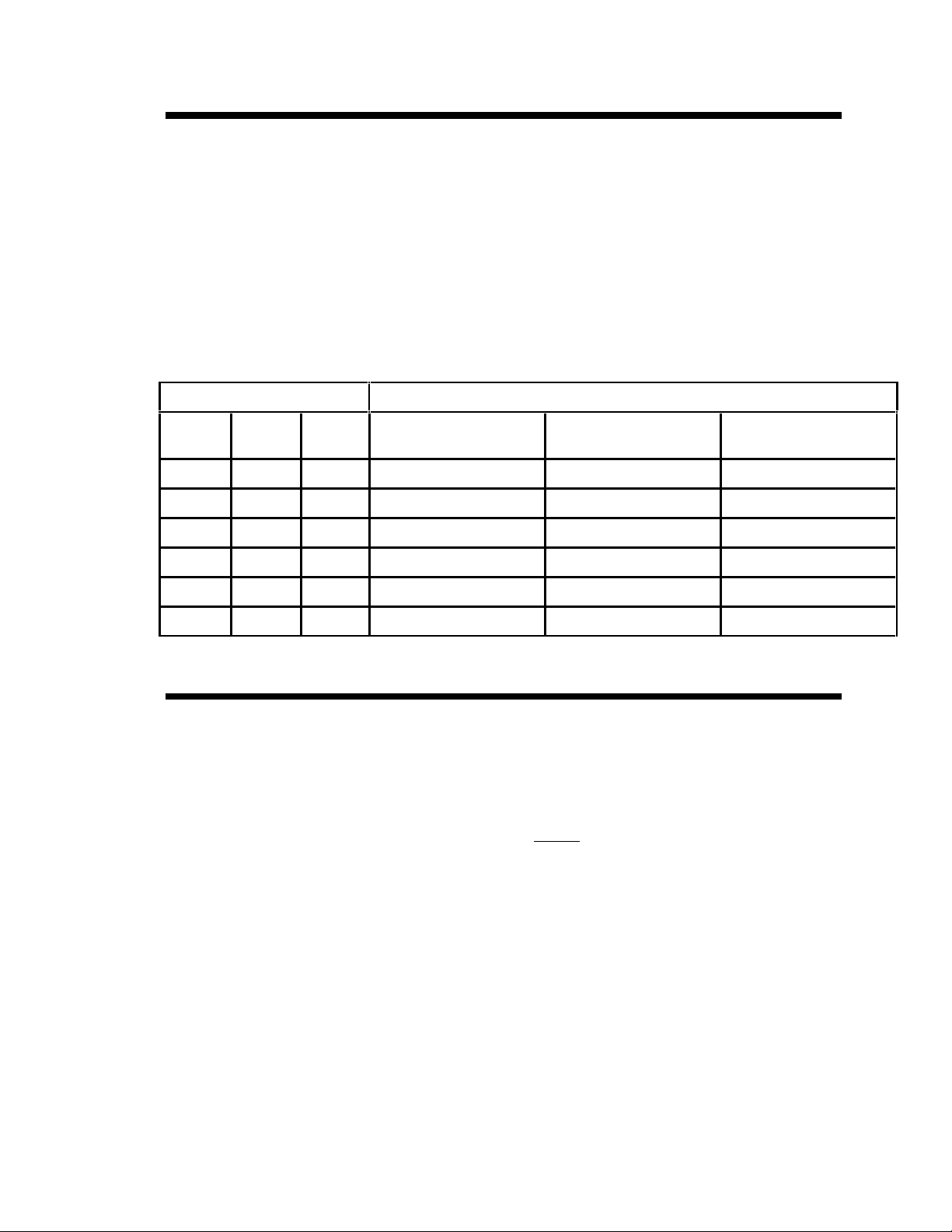
Packaging Materials
Thank you for choosing Trace Engineering products to meet your alternative-energy power needs. We
make every effort to ensure that your inverter/charger packaging includes the following materials:
Owner’s Manual;
Red, Black, & Green battery terminal covers (with hardware);
Hardware package for hardware covers;
Quick Setup Sheet
Hardwire Box with Hardware (2.4KW and larger inverters only)
Declaration of Conformity (Export models only)
Trace bumper sticker;
If any of the above listed materials are missing from your package, or if it is unsatisfactory in any
manner, please call Customer Service at (360) 435-8826 or fax this page with your comments to (360)
435-2229.
Model Number: _____________________________________
Serial Number: _____________________________________
Purchase Date: _____________________________________
Comments: _____________________________________________________________________
______________________________________________________________________________
______________________________________________________________________________
______________________________________________________________________________
______________________________________________________________________________
______________________________________________________________________________
Thank you for choosing Trace Engineering to meet your independent power needs. Check out our
web site at www.traceengineering.com for more information and answers to your FAQ’s.
Page 4

Page 5

Table of Contents
IMPORTANT SAFETY INSTRUCTIONS ..............................................................1
Theory of Inverter Operation..............................................................................3
Inverter Operation ...............................................................................................4
Front Panel Controls and LED Indicators................................................................................ 4
Power On/Off .............................................................................................................................. 4
Inverter Mode LED...................................................................................................................... 4
Search Mode Watts .................................................................................................................... 5
Over Discharge Protection and AC Transfer Voltage............................................................. 6
AC Transfer Voltage................................................................................................................... 7
Battery Bank Capacity ............................................................................................................... 7
Protection Circuitry.................................................................................................................... 8
Battery Charger ...................................................................................................9
Charger Terminology................................................................................................................. 9
Three Stage Battery Charging................................................................................................. 10
Battery Charger Controls and LED Indicator..................................................11
Battery Type Selector........................................................................................12
Battery Charger Settings..................................................................................13
Generator Requirements......................................................................................................... 14
Peak Voltage Available vs. Charge Rate Amps..................................................................... 14
Batteries.............................................................................................................15
Battery Terminology ................................................................................................................ 15
Selection of Battery Type........................................................................................................ 15
Battery Sizing............................................................................................................................ 17
Battery Care and Maintenance................................................................................................ 18
Monthly Maintenance............................................................................................................... 18
Battery Hook-up Configurations............................................................................................. 19
Battery Installation................................................................................................................... 20
INSTALLA TION..............................................................................................22
Environment ............................................................................................................................. 22
AC Wiring...........................................................................................................24
AC Connections........................................................................................................................ 24
Minimum Recommended Wire Sizes...................................................................................... 25
Ground Fault Interrupting Outlets (GFI’s).............................................................................. 25
DC Wiring...........................................................................................................26
DC Disconnect.......................................................................................................................... 26
DC Fusing ................................................................................................................................. 26
Battery Cable Connection ....................................................................................................... 27
Battery Cable Sizing................................................................................................................. 27
System Safety Wiring Requirements...............................................................28
Stacking Inverters.............................................................................................29
Connections.............................................................................................................................. 29
Operation .................................................................................................................................. 30
Theory of Operation................................................................................................................. 30
Search Mode Operation with Stacked Pairs.......................................................................... 30
RC4 Remote Control .........................................................................................31
Installation Diagrams........................................................................................32
A. Installation with Single AC Panel....................................................................................... 32
B. Installation with AC Sub Panel........................................................................................... 33
Page 6

C. Installation with External Relay......................................................................................... 34
Troubleshooting Guide..................................................................................... 35
Applications....................................................................................................... 37
Technical Information....................................................................................... 40
Performance Graphs......................................................................................... 41
Typical Battery Draw of Common Appliances................................................ 44
Other Products available from Trace Engineering......................................... 48
Limited Warranty............................................................................................... 49
Life Support Policy............................................................................................49
Table of Figures
FIGURE 1 , COMPARISON OF AC WAVEFORMS........................................................................ 3
FIGURE 2, CONTROL PANEL........................................................................................................ 4
FIGURE 3, ODP CONTROL............................................................................................................ 6
FIGURE 4, RECOMMENDED DISCHARGE CUTOFF VOLTAGE PER CELL.............................. 6
FIGURE 5, DR SERIES AC HARDWIRING .................................................................................. 24
FIGURE 6, INSTALLATION WITH A SINGLE AC PANEL............................................................ 32
FIGURE 7, INSTALLATION WITH AN AC SUB PANEL ............................................................... 33
FIGURE 8, INSTALLATION WITH EXTERNAL RELAY................................................................ 34
FIGURE 9, LOAD CAPACITY VS. TIME ....................................................................................... 41
FIGURE 10, POWER OUTPUT VS. EFFICIENCY........................................................................ 42
FIGURE 11, MAXIMUM REGULATED POWER OUTPUT VS. BATTERY VOLTAGE................. 43
FIGURE 12, DIMENSIONED DR SERIES INSTALLATION DRAWING ....................................... 47
Tables
TABLE 1, AC TRANSFER VOLTAGE ............................................................................................. 7
TABLE 2, BULK, FLOAT, AND EQUALIZE VOLTAGES FOR DR SERIES INVERTERS............ 12
TABLE 3, PEAK VOLTAGE VS. CHARGE RATE AMPS.............................................................. 14
TABLE 4, MAXIMUM CHARGE RATE WITH SOME TYPICAL GENERATOR MODELS............ 14
TABLE 5, MINIMUM RECOMMENDED WIRE SIZES................................................................... 25
TABLE 6, FUSE OR BREAKER SIZE REQUIRED VS. CABLE SIZE........................................... 26
TABLE 7, MINIMUM RECOMMENDED BATTERY CABLE SIZE (IN FREE AIR) ........................ 27
TABLE 8, TYPICAL BATTERY DRAW OF COMMON APPLIANCES (12V)................................. 44
TABLE 9, TYPICAL BATTERY DRAW OF COMMON APPLIANCES (24V)................................. 45
TABLE 10, ENGLISH TO METRIC WIRE CONVERSION TABLE................................................ 46
TABLE 11, SAFETY GROUND WIRE SIZE TABLE...................................................................... 46
Page 7

Trace Engineering DR Series Owner’s Manual - Version 3.2 - 9/7/98 - Page 1
IMPORTANT SAFETY INSTRUCTIONS
SAVE THESE INSTRUCTIONS !!
This manual contains important safety and operating instructions as prescribed by UL specifications
for inverters used in residential applications. This manual covers all DR series inverter/charger models.
The entire DR Series of inverters is ETL listed to the UL standard 1741 (Draft), Power conditioning
units for use in residential photovoltaic power systems. The DR series is also ETL listed to Canadian
standard CSA - C 22.2 No. 107.1 - M1, Commercial and Industrial Power Supplies.
General Precautions
1. Before using the inverter/charger, read all instructions and cautionary markings on (1) the
inverter/charger, (2) the batteries and (3) all appropriate sections of this instruction manual.
2. CAUTION - To reduce risk of injury, charge only deep-cycle lead acid, lead antimony, lead
calcium, gel cell, absorbed mat, or NiCad/NiFe type rechargeable batteries. Other types of
batteries may burst, causing personal injury and damage.
3. Do not expose inverter/charger to rain, snow or liquids of any type. The inverter is designed
for indoor mounting only. Protect the inverter from splashing if used in vehicle applications.
4. Do not disassemble the inverter/charger; take it to a qualified service center when service or
repair is required. Incorrect re-assembly may result in a risk of electric shock or fire.
5. To reduce risk of electric shock, disconnect all wiring before attempting any maintenance or
cleaning. Turning off the inverter will not reduce this risk. Solar modules produce power when
exposed to light - cover them with opaque material before servicing any connected
equipment.
6. WARNING - WORKING IN VICINITY OF A LEAD ACID BATTERY IS DANGEROUS.
BATTERIES GENERATE EXPLOSIVE GASES DURING NORMAL OPERATION. Provide
ventilation to outdoors from the battery compartment. The battery enclosure should be
designed to prevent accumulation and concentration of hydrogen gas in “pockets” at the top
of the compartment. Vent the battery compartment from the highest point. A sloped lid can
also be used to direct the flow to the vent opening location.
7. NEVER charge a frozen battery.
8. No terminals or lugs are required for hook-up of the AC wiring. AC wiring must be no less than
10 AWG (5.3 mm
rated for 75°C or higher and should be no less than 2/0 AWG (67.4 mm
and sealed copper ring terminal lugs with a 5/16 hole should be used to connect the battery
cables to the DC terminals of the inverter/charger. Soldered cable lugs are also acceptable.
See section on battery cable sizing for correct battery cable size and length for your
application.
9. Torque all AC wiring connections to 15-20 inch-pounds. Torque all DC cable connections to
10-12 foot- pounds. Be extra cautious when working with metal tools on, or around batteries.
The potential exists to drop a tool and short-circuit the batteries or other electrical parts
resulting in sparks that could cause an explosion.
2
) gauge copper wire and rated for 75°C or higher. Battery cables must be
2
) gauge. Crimped
Page 8

Trace Engineering DR Series Owner’s Manual - Version 3.2 - 9/7/98 - Page 2
Tools required to make AC wiring connections: Wire strippers, ½” (13MM) open-end wrench or
socket, Phillips screw driver #2, Slotted screw driver ¼” (6MM) blade.
10. This inverter/charger is intended to be used with a battery supply of nominal voltage that
matches the last two digits of the model number, e.g. 12 volts with a DR1512 or 24 volts with
a DR1524.
11. Instructions for wall mounting: See mounting instruction section of this manual. NOTE: Do not
use only the keyhole mounting slots for permanent installations. For battery installation and
maintenance: read the battery manufacturer’s installation and maintenance instructions prior
to operating.
12. No AC or DC disconnects are provided as an integral part of this inverter. Both AC and DC
disconnects must be provided as part of the system installation. See INSTALLATION section
of this manual.
13. No overcurrent protection for the battery supply is provided as an integral part of this inverter.
Overcurrent protection of the battery cables must be provided as part of the system
installation. See INSTALLATION section of this manual.
14. No overcurrent protection for the AC output wiring is provided as an integral part of this
inverter. Overcurrent protection of the AC output wiring must be provided as part of the
system installation. See INSTALLATION section of this manual.
15. GROUNDING INSTRUCTIONS - This battery charger should be connected to a grounded,
permanent wiring system. For most installations, the negative battery conductor should be
bonded to the grounding system at one (and only one point) in the system. All installations
should comply with all national and local codes and ordinances.
Personal Precautions
1. Someone should be within range of your voice to come to your aid when you work near
batteries.
2. Have plenty of fresh water and soap nearby in case battery acid contacts skin, clothing, or
eyes.
3. Wear complete eye protection and clothing protection. Avoid touching eyes while working
near batteries. Wash your hands when done.
4. If battery acid contacts skin or clothing, wash immediately with soap and water. If acid enters
eyes, immediately flood eyes with running cool water for at least 15 minutes and get medical
attention immediately.
5. Baking soda neutralizes lead acid battery electrolyte. Vinegar neutralizes spilled NiCad and
NiFe battery electrolyte. Keep a supply on hand in the area of the batteries.
6. NEVER smoke or allow a spark or flame in vicinity of a battery or generator.
7. Be extra cautious when working with metal tools on, and around batteries. Potential exists to
short-circuit the batteries or other electrical parts which may result in a spark which could
cause an explosion.
8. Remove personal metal items such as rings, bracelets, necklaces, and watches when
working with a battery. A battery can produce a short-circuit current high enough to weld a
ring, or the like, to metal causing severe burns.
9. If a remote or automatic generator start system is used, disable the automatic starting circuit
and/or disconnect the generator from its starting battery while servicing to prevent accidental
starting during servicing.
Page 9
Trace Engineering DR Series Owner’s Manual - Version 3.2 - 9/7/98 - Page 3
Theory of Inverter Operation
Waveform
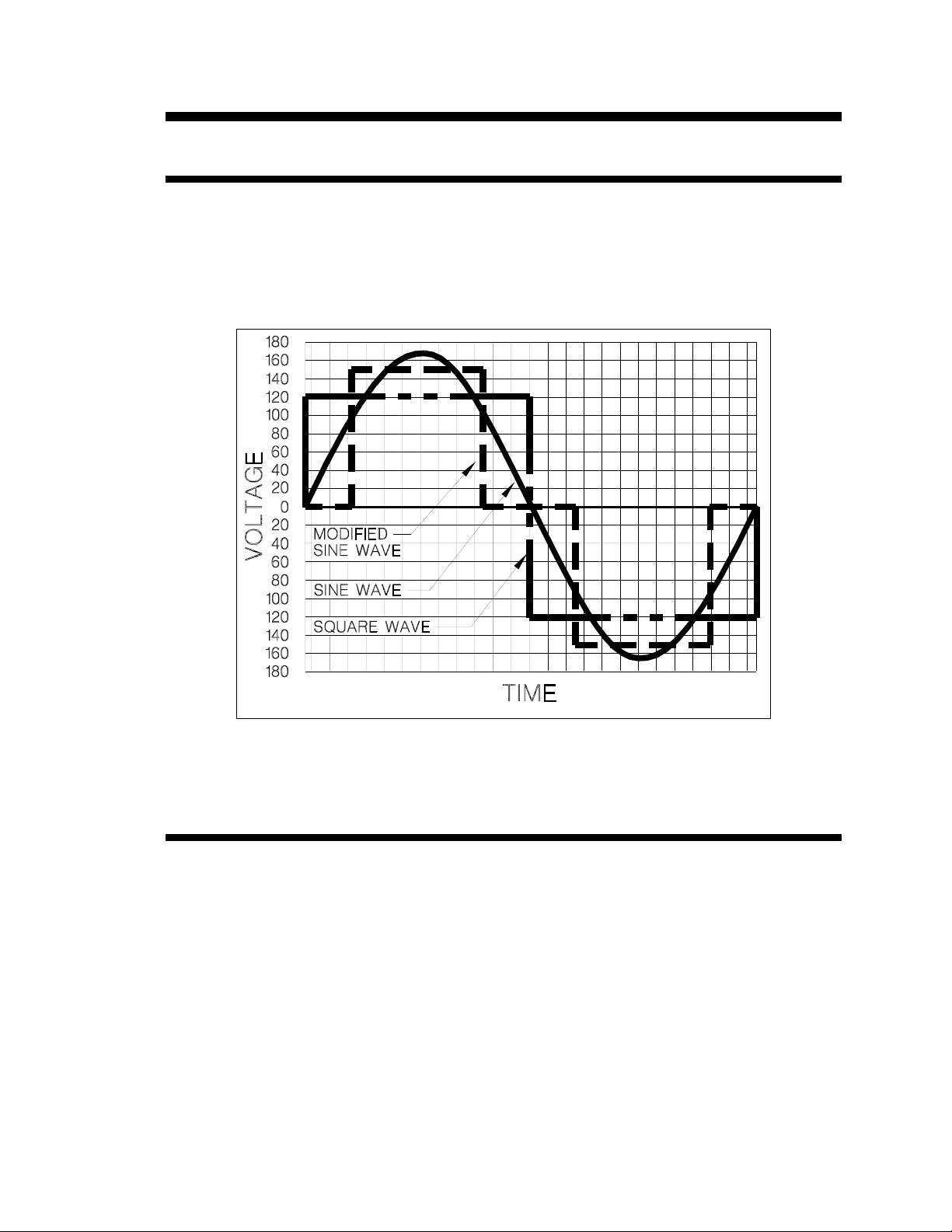
The output waveform of the inverter is referred to as a modified sine wave. This waveform is suitable
for a wide variety of applications. Induction motors (i.e. refrigerators, drill presses), resistive loads (i.e.
heaters, toasters), universal motors (i.e. hand tools, vacuum cleaners) as well as microwave ovens
and computers are all suitable loads.
Figure 1 , Comparison of AC Waveforms
The waveform could be more accurately described as a pulse width modified square wave. The
accompanying Figure 1 shows the relationships between square wave, sine wave and modified sine
wave formats.
Regulation
The inverter is RMS voltage regulated. RMS regulation ensures that loads will always have the
same amount of power delivered to them as battery voltage changes. Regulation is achieved by
varying the width of each output pulse in the waveform. Peak voltage is the product of the battery
voltage times the turns ratio of the inverter’s power transformer and is therefore not regulated.
Page 10
Trace Engineering DR Series Owner’s Manual - Version 3.2 - 9/7/98 - Page 4
Inverter Operation
Front Panel Controls and LED Indicators
Shown below are the controls and indicator lights on the front of the DR series inverter/charger. These
control and provide information when in either inverter or battery charging mode of operation. All
models of the DR series operate identically.
Figure 2, Control Panel
Power On/Off
Located on the left of the panel is the momentary POWER ON/OFF button. Once the inverter has been
properly installed and the batteries are connected, pressing this button momentarily will alternately turn
the inverter on and off. Each time it is pressed the inverter will sound an audible chirp. Note: When
first connected to batteries, the inverter will run through a self-test, and go to an off state. It may then
be activated by pressing the on/off button. Note: The self-test consists of the control panel lights
lighting up in sequence, the internal cooling fan will run momentarily, and the transfer relay will click
three times.
Inverter Mode LED
This green LED indicator lights when the unit is in the inverter mode (not charging batteries) delivering
full output voltage. When the inverter is in its search mode the green LED will blink about 2-3 times per
second.
Page 11

Trace Engineering DR Series Owner’s Manual - Version 3.2 - 9/7/98 - Page 5
Search Mode Watts
The SEARCH MODE WATTS control is used for adjusting the sensitivity of the search mode circuit.
The DR Series inverters feature a circuit that minimizes power drain by reducing the inverter’s output
to small test pulses when there is no load connected to the inverter. These pulses are used to detect
the presence of a load. When a load is detected the inverter’s output goes to full voltage. The
sensitivity of the detection threshold is adjustable. Turning the SEARCH MODE WATTS control
clockwise decreases the sensitivity. Turning the control full counterclockwise increases sensitivity and
at the full counterclockwise position, defeats the search mode feature.
Example: With the SEARCH MODE WATTS control set to detect a 40 watt load, a 50 watt load will
bring the unit to full output voltage. However, a 30 watt load will leave the inverter in its energy saving
search mode state. If the sensitivity is increased by setting the control to 10, a 20 watt load will bring
the inverter out of the search mode, while a 5 watt load will not.
When in the search mode, the green power LED will blink and the inverter will make a ticking sound.
At full output voltage, the green power LED will remain lit and the inverter will make a steady buzzing
sound. When the inverter is used as an uninterruptable power supply, the search mode function
should be defeated by turning the control completely to the left (counter clockwise).
A neon type nightlite can also be used as a good indicator to determine if the inverter is in search
mode. Simply plug the light into any AC outlet that is connected to the inverter’s output. When the
inverter is in the search mode the light will blink. If the inverter is running a load, the light will be on
continuously.
Exceptions: (Murphy’s Law) Unfortunately, things don’t always work the way the manual says they
will.
Example A: If the SEARCH MODE WATTS control is set to detect a 40 watt load and a 30 watt
incandescent light is turned on, the inverter will detect the light. The light is a bigger load than 40 watts
when its filaments are cold. When the light gets hot it becomes a 30 watt load. Since this is below the
control setting of 40, the inverter will not detect it and the light will go out. This will cause the light to
cycle repeatedly.
Example B: If the SEARCH MODE WATTS control is set to detect a 30 watt load and a 40 watt
fluorescent light is turned on, the inverter will not detect the light. The light presents a smaller load than
30 watts until the gas in the fluorescent tube ionizes.
Example C: There are some appliances that draw power even though they are turned off. TVs with
instant on circuits, microwave ovens with digital displays and VCRs are examples. These loads
present a dilemma. If the sensitivity is set higher than the combination of these loads, then an auxiliary
load must be used to bring the inverter out of the search mode before the appliances can be turned
on. If the sensitivity is set lower than this combination of loads, the loads will be left on and will put an
additional drain on the batteries. (Three such 15 watt loads would amount to an additional 90
amp/hours per 24 hours in a 12 VDC system.)
One solution is to turn these items off at the wall. Use an extension cord with a rocker switch, a switch
at the outlet, or the appropriate circuit breaker. Another solution might be to place all these phantom
loads on a separate circuit with its own disconnect.
Page 12
Trace Engineering DR Series Owner’s Manual - Version 3.2 - 9/7/98 - Page 6
Over Discharge Protection and AC Transfer Voltage
This control enables or disables the over discharge protection system (ODP) and allows adjustment of
the AC transfer voltage. With the dial set to either the left or right side of the scale, transfer voltage can
be adjusted from minimum to maximum. The voltage will vary depending on the model of inverter you
have. See the chart on the next page for transfer voltage values.
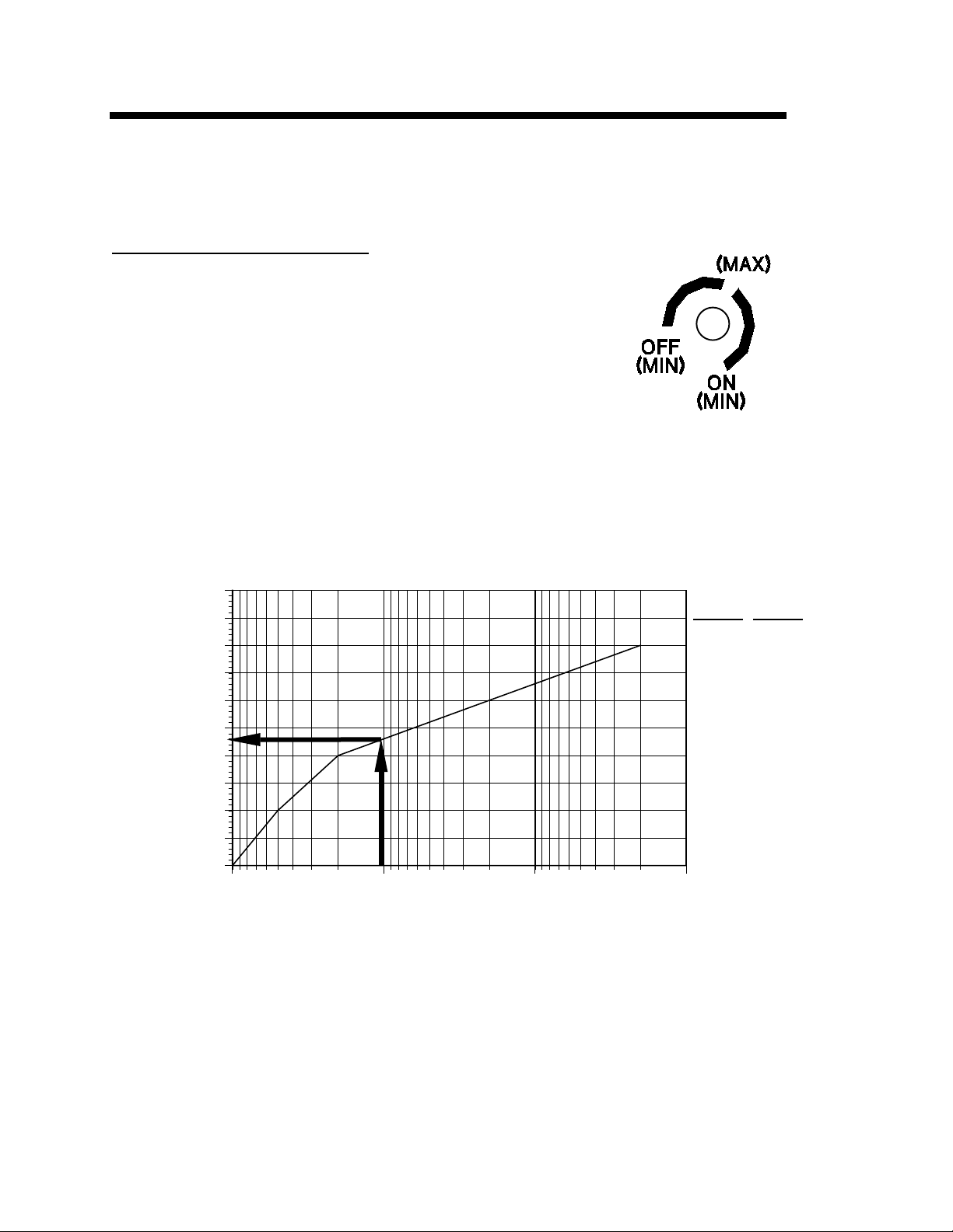
ODP (AC Transfer Voltage) Control
Located on the right of the control panel is the OVER-DISCHARGE
PROTECTION control. This circuit is unique to Trace Inverters. Its
purpose is to protect the batteries from being over-discharged. This
circuit monitors both the current being drawn by the inverter and the
battery voltage. Battery voltage alone is not an accurate indicator of
battery condition. The internal resistance of a battery causes its
output voltage to drop when the battery is delivering current. The
smaller the battery, the greater the voltage drop for a given load. This
battery voltage drop due to load is not an indicator of the battery’s
state of charge. The Trace “load compensated” circuit uses
information about the battery bank size, temperature and the load
current to derive a corrected battery voltage. Below is a chart showing
the maximum discharge voltage per cell for different load currents and
battery sizes. For example: A battery bank with a 1000 amp-hour capacity being discharged by a load
requiring 100 amps/hour has a factor of 0.1 (100/1000). Enter the chart from the bottom at 0.1,
proceed up to the curve and then to the left. This shows that a minimum voltage of 1.73 volts per cell
should be observed. This chart is useful when customizing the DR inverter to different size systems.
Figure 3, ODP Control
2
1.95
C
1.9
e
1.85
l
l
1.8
V
1.75
o
1.7
l
t
1.65
12VDC
12.0
11.4
10.8
24VDC
24.0
22.8
21.6
a
1.6
g
e
1.55
1.5
1 0.1 0.01 0.001
Discharge Rate/ Battery Capacity
10.2
9.6
9.0
20.4
19.2
18.0
Figure 4, Recommended Discharge Cutoff Voltage per Cell
The over discharge protection control is turned clockwise to activate the circuit. It is defeated by
turning the control fully counterclockwise. If the over discharge circuit is defeated, the inverter itself is
protected from low battery voltage conditions by an additional low battery protection circuit which has a
threshold of 8.2 volts DC.
Page 13
Trace Engineering DR Series Owner’s Manual - Version 3.2 - 9/7/98 - Page 7
AC Transfer Voltage
When the AC source (either public power or a generator) fails or falls to a low level (browns out), the
unit changes from battery charger mode to inverter mode. The AC voltage point at which the inverter
decides to change modes is called the AC transfer voltage. It is adjustable from minimum to maximum.
The adjustment is made by rotating the ODP knob between the 9:00 and 1:00 o’clock position if you
want the ODP defeated, or by rotating the knob between 2:00 and 5:00 o’clock if you want the ODP
enabled. As the knob is turned clockwise the transfer voltage increases if the ODP is defeated, or
decreases if the ODP is enabled. It is best to set the transfer voltage by first rotating the control all the
way to the left (off position), then to the desired position. See Figure 3.
Below is a chart showing the AC transfer voltages depending on the particular AC input/output voltage
of the unit. Note that adjusting the dial to a higher voltage setting results in slightly faster transfer
times, since it will take less of a voltage drop to trigger the transfer. Lower settings are less likely to
cause a transfer due to voltage fluctuations.
ODP ADJUSTMENT AC TRANSFER VOLTAGE
ODP
OFF
9:00 (MIN) 5:00 36 VAC 40 VAC 80 VAC
1:00 (MAX) 2:00 95 VAC 105 VAC 210 VAC
ODP
ON
100 - 105 VAC UNITS
(J OR K)
77 VAC 85 VAC 170 VAC
81 VAC 90 VAC 180 VAC
86 VAC 95 VAC 190 VAC
90 VAC 100 VAC 200 VAC
120 VAC UNITS (USA) 220 - 240 VAC UNITS
(W OR E)
Table 1, AC Transfer Voltage
Battery Bank Capacity
The BATTERY CAPACITY control is used to inform the inverter’s microprocessor about the size of the
battery bank being used. The microprocessor uses the formula of “battery capacity/40” to determine
what current level the bulk/absorption charge terminates (a maximum time of 12 hours is allotted for
bulk/absorption charge) and the float charge stage begins. This allows the inverter to make better
“Over-Discharge Protection” and battery charging decisions. Battery bank size is adjustable from 50 to
1000 (1K) amp-hours. Set this adjustment to the setting closest to the size of your battery bank (in
amp-hours).
Note: .37K = 370 amp-hours, .5K = 500 amp-hours, an 1K = 1000 amp-hours. If your battery bank is
1000 amp-hours or greater, adjust the BATTERY CAPACITY control to the 1K position.
Page 14

Trace Engineering DR Series Owner’s Manual - Version 3.2 - 9/7/98 - Page 8
Protection Circuitry
The inverter will automatically restart itself from the following overload conditions: low battery, high
battery, shorted output, over current, and over temperature.
The inverter will turn itself off and require a manual restart if it encounters an overload for
approximately 10 seconds (a prolonged short circuit), or if AC output is directly connected to an AC
power source (public power or generator).
Two LED’s are provided to report on error conditions:
BATTERY HI RED/ BATTERY LOW GRN - This LED lights red when battery voltage is too high for
safe operation, and is green when voltage is too low for safe operation. When the voltage returns to a
safe level, the inverter restarts automatically.
In alternative energy applications (solar, wind, hydro) all DC charge controllers must be set to a
Note:
level below the inverter’s MAXIMUM INPUT VOLTAGE or the inverter may shut off unexpectedly. The
maximum input voltage for DR series inverters is, 15.5 volts DC for 12 volt inverters, and 31.0 volts DC
for 24 volt models.
Note: The battery charger control circuit operates from battery voltage. If battery voltage falls below 7
volts, neither the charger nor the inverter will operate. In this situation, a small charge from a standalone charger will be required to bring the battery to a high enough voltage for the inverter/charger to
resume operation.
OVERTEMP RED / OVERLOAD GRN- This LED lights red when the inverter’s temperature is too high
for safe operation and is green if the load is too large for the inverter to safely operate. When the
temperature returns to a safe level, the inverter restarts. The inverter will restart automatically if the
overload condition lasts for less than 10 seconds.
If the green overload LED is on when the unit is in the charger or search modes then there is a charger
fault. This means that the charger is charging even though the regulation system is trying to turn it off.
The unit will turn this LED on when a fault is detected, and will continue for up to one hour if the
condition persists. After this period the charger will shut down, disconnect the relay and continue to
display the green overload LED. The unit may be reset manually by pressing the power on/off switch,
and will continue to operate for another one hour period if the condition has not been corrected. The
inverter portion will continue to work normally throughout this type of fault. Contact your Trace
Engineering service center for repair if this type of fault is encountered.
The green overload LED will also come on in the event of a “backfeed” condition. This condition
could occur if AC power is applied to the inverter’s output. The LED will light from 1-10 seconds
when the condition is detected, after which the inverter will shut down. To correct this condition
remove the AC input power from the inverter’s output. The unit must then be reset by pressing the
power on/off switch.
Caution: Repeated connection of an AC source directly to the AC output may cause
damage to the inverter.
Page 15

Trace Engineering DR Series Owner’s Manual - Version 3.2 - 9/7/98 - Page 9
Battery Charger
Theory of Operation
Inverter to Charger Transition
The internal battery charger and automatic transfer relay allows the unit to operate as either a battery
charger or inverter (but not both at the same time). An external source of AC power (e.g., shore power
or generator) must be supplied to the inverter’s AC input in order to allow it to operate as a battery
charger. When the unit is operating as a charger, AC loads are powered by the external source (i.e.
generator or public power).
The inverter automatically becomes a battery charger whenever AC power is supplied to its AC inputs.
There is a 40 second time delay from the time the inverter senses that AC is present at its input and
when the transfer is made. This delay is built in to provide time for a generator to spin-up to a stable
voltage and avoid relay chattering. The inverter’s AC input is internally connected to the inverter’s AC
output while in the battery charger mode. The maximum power that can be handled by the inverter’s
internal wiring and transfer relay is 30 amps (20 amps for export models).
Transfer Switching Speed
While this inverter is not designed specifically to operate as an uninterruptable power supply (UPS)
system, its transfer time is normally fast enough to hold up computers. The transfer time is a maximum
of 32 milliseconds. Success as a UPS will vary with computer models, and cannot be guaranteed.
Charger Terminology
•
Bulk Voltage- This is the maximum voltage at which the batteries will be charged during a
normal charging cycle. The normal range is 2.367 to 2.4 volts per cell. For a 12 VDC battery
(6 cells) this is 14.2 to 14.4. Liquid electrolyte batteries are usually set to the higher voltage,
while gel cell batteries are set to the lower voltage. (See page 18, Battery Care and
Maintenance, ”Bulk Voltage”).
•
Absorption - During this part of the charge cycle, the batteries are held at the bulk voltage
and accept whatever current is required to maintain this voltage. This ensures full charging.
• Float Voltage - This is the voltage at which the batteries will be maintained after they have been
charged. A range of 13.2 -13.4 for 12 volt systems is appropriate for most sealed and non-sealed
batteries. 13.2 volts is appropriate for gel cell batteries, and 13.4 volts is common for liquid lead
acid types. Check with the specific battery manufacturer for actual float voltage figures.
•
Equalize - The batteries are held above 15.0 Volts DC for a period to “boil” or mix the cells thus
reducing stratification and lead sulfate build-ups. This is not necessary or safe with sealed
batteries.
Page 16
Trace Engineering DR Series Owner’s Manual - Version 3.2 - 9/7/98 - Page 10
d
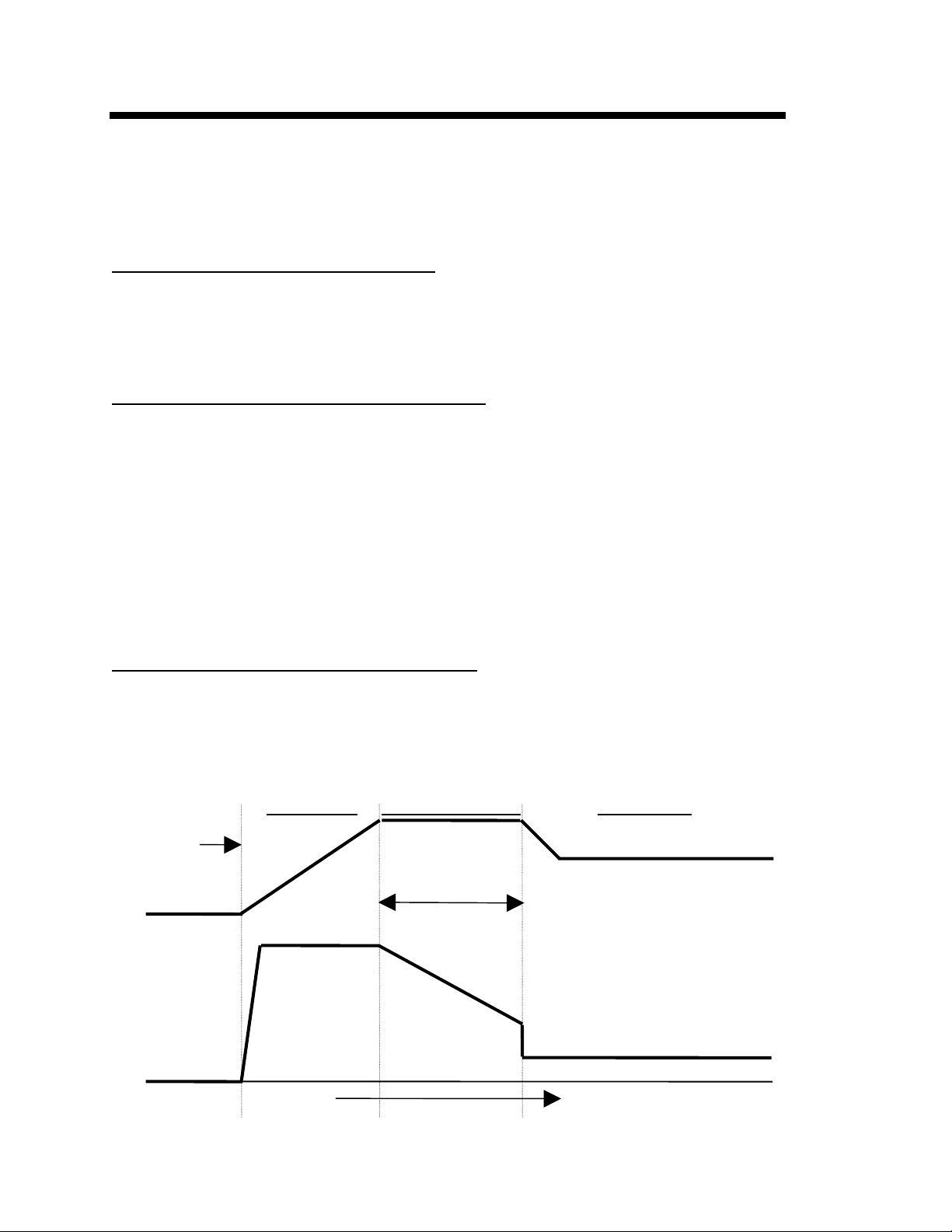
Three Stage Battery Charging
The battery charger in the Trace DR series inverters, charges in three stages - BULK, ABSORPTION,
and FLOAT - to provide rapid and complete charge cycles without undue battery gassing. A manually
operated equalize stage is provided for periodic battery maintenance. The time diagram at the bottom
of this page shows how DC voltage and AC current change with time through the different charge
stages.
Stage One - Constant Current (Bulk Charge)
This stage is initiated when AC is applied to the AC input of the inverter, and is terminated when the
batteries reach the BULK CHARGE VOLTAGE. During this stage the Charger LED glows steady
orange.
Stage one charges the batteries at a constant current. The level of charge for this phase is set using
the BATTERY CHARGER RATE control on the front panel.
Stage Two - Constant Voltage (Absorption Charge)
Absorption is initiated when the Bulk Voltage setting is reached. At this point the charge current begins
to taper off at whatever rate is required to hold the voltage constant. During this stage the Charger
LED blinks orange. The absorption charge phase is terminated in one of two ways.
1. Normally, as the charge cycle progresses, the current required to hold the battery voltage
constant gradually reduces. When this current equals the programmed return amps setting
(battery bank capacity/40), the voltage is allowed to fall to the FLOAT (float voltage) setting stage three.
2. If there are DC loads on the batteries, the current may never fall to a level low enough to
initiate the float voltage stage. A timer is used to ensure that the battery voltage does not
remain indefinitely at the Bulk Charge Voltage. The timing circuit is activated by the onset of
stage two, it terminates stage two if the charge current does not reach the return amps value
setting within 12 hours.
Stage Three - Maintenance Voltage (Float Charge)
The charger remains in the float stage until the unit is turned off or loses AC input power (i.e. generator
or grid). During this stage the Charger LED glows steady green. The purpose of stage three is to
maintain the batteries at a voltage that will hold full charge but not gas the batteries.
Note: When DC loads are placed on the battery, the charger will deliver currents up to the Maximum
Charge Rate setting while maintaining the float voltage.
Bulk Charge Absorption Charge Float Charge
Charging
Bulk Volts Setting
Starte
Float Volts Setting
Absorption Time
DC Voltage
Battery Charge
Rate
3- Stage Battery Charger
DC Voltage and AC current
Charge Profile
AC Current
Constant Current
Constant Voltage
Reduced Current and Voltage
Time
Page 17

Trace Engineering DR Series Owner’s Manual - Version 3.2 - 9/7/98 - Page 11
Battery Charger Controls and LED
Indicator
A three state LED reports on the activity of the battery charger. Controls are provided that make it
simple to tailor the charger’s characteristics for various types of batteries.
Charger LED
Labeled “CHARGER: GRN=FLOAT/ORN BLINK=ABSORP/ORN= BULK”, this bi-color LED indicates
charge status as follows:
•
Orange - this indicates that the charger is in the bulk charging stage.
•
Blinking Orange - this indicates that the charger is in the absorption stage.
•
Green - this indicates that the charger is in the float stage.
Note: The bi-color LED used has the ability to show red, green, or orange in color. By
simultaneously showing red and green the orange color is obtained. To avoid confusion as to
which color is being displayed, view the LED from directly in front of the unit. Do not view it at
an angle.
Battery Charger Rate
This control sets the maximum charge rate in amps. The highest charge rate recommended is
determined by dividing the battery bank’s total amp hour capacity by a factor between 3 and 5 (3
for gel cell - 5 for lead acid). Setting the BATTERY CHARGER RATE at the highest
recommended level is best when the objective is to charge the batteries as quickly as possible. A
much lower setting can be used in installations where AC power is typically available for periods of
several hours. For example: there is more than sufficient time for a 400 amp/hr battery bank to be
recharged in 24 hours at a 25 amp setting - 25 amps X 24 hours = 600 amp-hours.
Caution: Excessively high charge rates can overheat a battery. If a small battery capacity is used,
set the battery charger rate to the minimum setting.
Page 18
Trace Engineering DR Series Owner’s Manual - Version 3.2 - 9/7/98 - Page 12
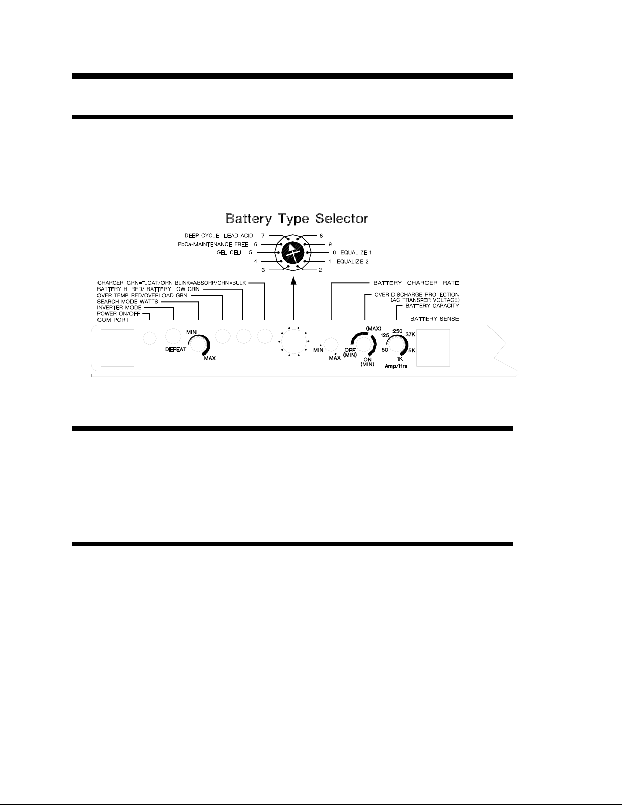
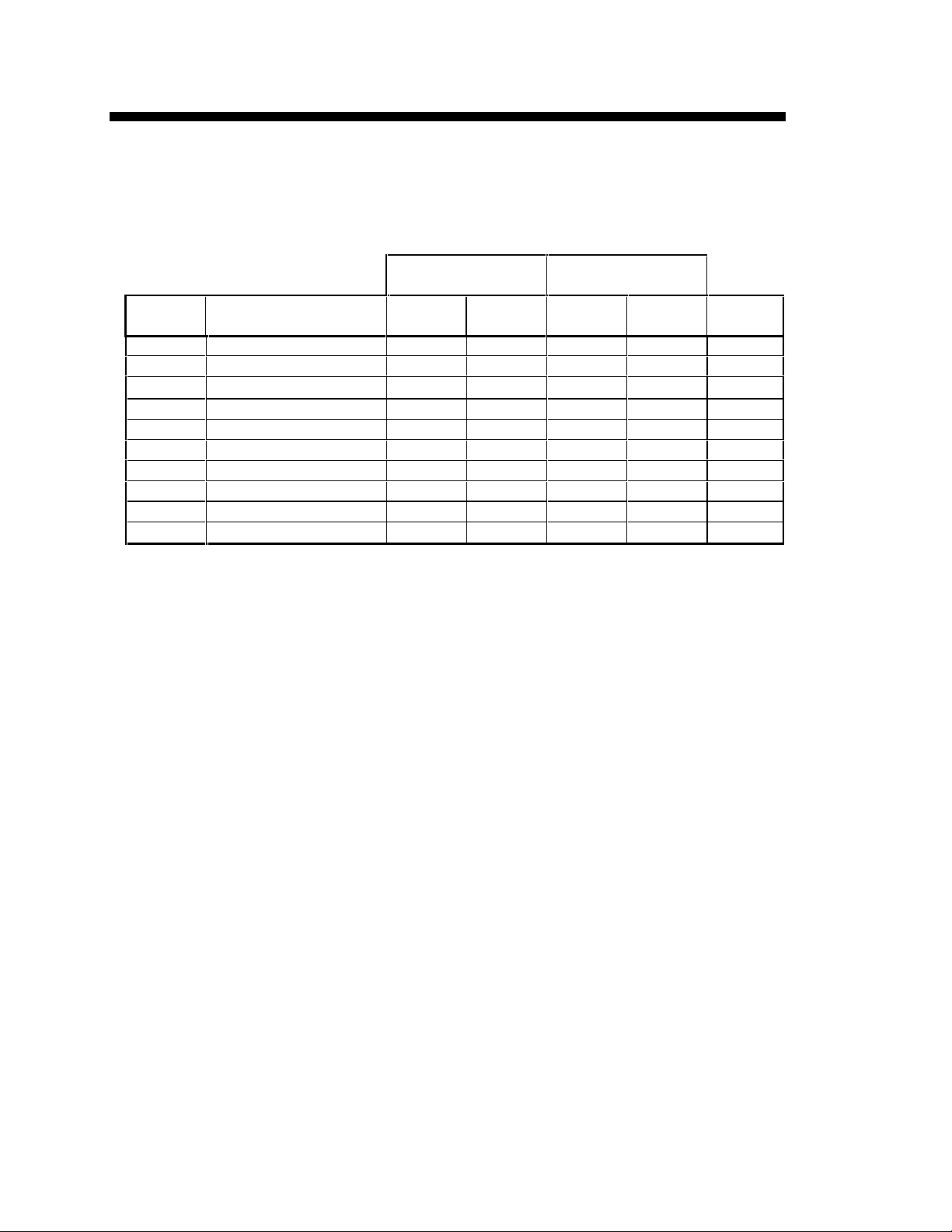
Battery Type Selector
This control automatically sets the correct bulk and charge voltages according to the type of battery
selected. The switch has ten positions. Each position provides different charge parameters. Select the
correct position according to the following table. (See the section “Battery Charger Setting” on the
next page, for specific applications and hints.)
12 VOLT MODELS 24 VOLT MODELS
Switch
Position
0 Equalize 1 13.2 15.0 26.4 30.0 c/40
1 Equalize 2 13.2 15.5 26.4 31.0 manual
2 Deep Cycle Lead Acid 2 13.3 15.0 26.6 30.0 N/A
3 Not Specified 13.6 14.3 27.2 28.6 N/A
4 Gel Cell 2 13.7 14.4 27.4 28.8 N/A
5 Gel Cell 13.5 14.1 27.0 28.2 N/A
6 PbCa- Lead Calcium 13.2 14.3 26.4 28.6 N/A
7 Deep Cycle Lead Acid 13.4 14.6 26.6 29.2 N/A
8 NiCad 1 14.0 16.0 28.0 32.0 N/A
9 NiCad 2 14.5 16.0 29.0 32.0 N/A
Table 2, Bulk, Float, and Equalize Voltages for DR Series Inverters
Position 0 and 1 - These positions may be used to equalize lead acid batteries. Equalizing is
discussed in the next chapter “Batteries”. These positions are unique in that the batteries are held at
the bulk voltage for a minimum of six hours. Position 0 equalizes at a rate equal to the battery capacity
in amp hours divided by 40. Position 1 charges at a rate set by the BATTERY CHARGER RATE
control. DO NOT USE THESE POSITIONS WITH SEALED BATTERIES!
Position 2 - Provides different bulk and float settings for deep cycle lead acid batteries as
compared to position 7. Consult the battery manufacturer for recommended bulk and float
settings.
Description Float
Voltage
Bulk
Voltage
Float
Voltage
Bulk
Voltage
Equalize
Rate
Position 3 - Provides an additional set of bulk and float voltages.
Position 4 - Recommended for gel cell batteries that specify high float voltages. Check with the
battery’s manufacturer.
Position 5 - Typical gel cell setting.
Position 6 - Use this setting for sealed type car batteries.
Position 7- Factory setting for typical deep cycle lead acid batteries.
Position 8 - For use with NiCad battery systems. See the following section “Batteries” for alternate
recommendations when using NiCads.
Position 9 - Recommended for use with Nickel Iron batteries.
Page 19

Trace Engineering DR Series Owner’s Manual - Version 3.2 - 9/7/98 - Page 13
Battery Charger Settings
BATTERY TYPE AND BULK FLOAT DR BATTERY
MANUFACTURER VOLTAGE VOLTAGE SELECTOR POSITION
GEL CELL BATTERIES
East Penn/Sonnenschein/Prevailer 14.1 13.8 5 GEL
Series
Interstate SG type 14.4 13.6 4 (gel cell 2)
Johnson Controls/Dynasty GC series 14.4 13.6 4 (gel cell 2)
East Penn/Deka 8G series 14.1 13.8 5 GEL
GNB Not yet determined
JCI Not yet determined
ABSORBED ELECTROLYTE BATTERY
Generic Absorbed Electrolyte 14.5 13.8 4 (gel cell 2)
LIQUID LEAD ACID BATTERY
Rolls 4000 or Surrete 400 ?14.4 ?13.8 4 (gel cell 2)
Generic Automotive 14.4 13.6 4 (gel cell 2)
LIQUID LEAD CALCIUM (FLOODED) TELEPHONE BATTERY
C and D Powerco 14.3 13.4 4 (gel cell 2)
General Guidelines
EQUALIZATION-
•
Do not equalize gel types or starved electrolyte types (Starved electrolyte batteries are
batteries such as absorbed glass mat (AGM) batteries in which the electrolyte is minimal and
is contained in the plate separators).
•
Equalize once every 30 days if medium cycled service. Less if battery spends most of time in
Float mode.
CHARGING-
•
Max charge current is typically 20-30% of batteries total capacity
•
Do you think the charger is going to float stage too soon? --
♦
Turn battery size pot CCW to decrease return amps.
♦
Decrease charge rate if on grid power.
♦ Make sure battery reaches gassing point if liquid type.
♦ Turn charge pot down below 70% of max to disengage sync FETS to aid charging.
Page 20

Trace Engineering DR Series Owner’s Manual - Version 3.2 - 9/7/98 - Page 14
Generator Requirements
The maximum charge rate of the battery charger is dependent upon the peak AC voltage available.
Since the battery charger uses only the top portion of the input sine wave, small variations in peak
voltage result in large variations in the amount of energy to the charger*. This charger’s output is rated
on the basis of public power input which has a peak voltage of 164V (230V AC power has a peak
voltage of 330).
It takes a powerful AC generator set to maintain the full 164 volt peak while delivering the current
necessary to operate the charger at its maximum rate (typically 5KW for 2500VA models and 2.5KW
for 1500VAt models). Smaller generators will have the tops of their waveform clipped under such
loads. Running at these reduced peak voltages will not harm the charger, but it will limit the maximum
charge rate. Large auxiliary AC loads may exacerbate this problem.
Peak Voltage Available vs. Charge Rate Amps
PEAK VOLTAGE
AVAILABLE
170 VOLTS 70Amps 120Amps 35Amps 70Amps 70Amps
160 VOLTS 35Amps 60Amps 17.5Amps 35Amps 35Amps
145 VOLTS 15Amps 25Amps 7Amps 15Amps 15Amps
Table 3, Peak Voltage vs. Charge Rate Amps
DR1512 DR2412 DR1524 DR2424 DR3624
Generator Examples: Typical Maximum Charge Rate
Amps
Table 4, Maximum Charge Rate with some Typical Generator Models
GENERATOR TYPE INVERTER TYPE TYPICAL MAX CHARGE
RATE AMPS
Honda 800 Trace DR1512 43 Amps
Honda 2200 Trace DR1512 57 Amps
Homelite 2500 Trace DR1512 11 Amps
Honda 3500 Trace DR1512 39 Amps
Honda 6000 Trace DR1512 70 Amps
Honda 1600 Trace DR1524 25 Amps
Westerbeke 7.0KW Trace DR1512 About 45 Amps
Westerbeke 12.5KW Trace DR1512 About 65 Amps
*This characteristi c is due to the fact t hat the battery charger’s DC output is the dividend of the transformer turns ratio. In
example, if a transform er has a 10:1 turns ratio, a 164 volt AC input voltage shows up as approximately 16. 4 vol ts at the
low DC side of the charger after recti f i cation and filtering (164/10), 140 vol ts AC becomes approximat el y 14.0 volts DC,
etc. Any peak AC voltage below about 130 volt AC is pretty much us el ess for charging as it only provi des roughly 13.0
volts DC.
Page 21

Trace Engineering DR Series Owner’s Manual - Version 3.2 - 9/7/98 - Page 15
Batteries
Batteries come in different sizes, types, amp hours, voltages and chemistries. There are nearly as
many descriptions of exactly how batteries should be charged as there are people willing to offer
explanations. It is not possible here to discuss all aspects in detail. However, there are basic
guidelines you can follow that will help in battery selection and ensure that your batteries are better
maintained than the majority.
Note: The battery manufacturer is the final authority as to the care and application of any battery.
Battery Terminology
A description of battery types and care requires the use of terms with which you may not be familiar.
The following terms will be referred to in the description of battery types, care, and connection.
• Electrolyte- Typically a mixture of water and sulfuric acid, it is commonly referred to as battery
acid.
• Plates- Originally made of lead, they are now made of lead oxide. Plates are the part of the
battery that collect current and are connected to the battery terminals. There are several plates in
each cell, each insulated from the other by separators.
• Sulfating - As a battery discharges, its plates are progressively covered with lead sulfate. During
recharging, the lead sulfate is removed from the plates and recombined with the electrolyte. If the
lead sulfate remains on the plates for an extended period of time (over two months), it hardens,
and recharging will not remove it. This reduces effective plate area and the battery capacity is
diminished.
• Stratification - Over time the batteries’ electrolyte (liquid) tends to separate. The electrolyte at the
top of the battery becomes watery while at the bottom it becomes more acidic. This effect is
corrosive to the plates and reduces battery life.
• Deep Cycle - A deep cycle occurs when a battery has been discharged such that less than 20%
of its capacity remains (80% discharge).
•
Temperature Compensation - The optimum full charge voltage is temperature dependent. As
temperature decreases the proper voltage for each charge stage needs to be increased. The
optional temperature probe will automatically re-scale charge voltage settings for ambient
temperature. The compensation slope based on cell voltage is -2.17mv per degree F. per cell.
This also decreases the charge voltage when the battery is hot to reduce gassing.
Selection of Battery Type
Starting Batteries
These are designed for high cranking power, but not deep cycling. Don’t use them. It does not hurt the
inverter - they simply will not last long in a deep cycle application. The way they are rated should give
a good indication of their intended use. - “Cold Cranking Amps”, a measure of the amperage output
that can be sustained for 30 seconds. Starting batteries use a lot of thin plates to maximize the surface
area of the battery. This allows very high starting current but lets the plates warp when the battery is
cycled.
Telephone Company Batteries
Second-hand telephone company batteries are often available at far below original cost. They are
often used to power the telephone system for short power outages. They are sometimes used
successfully in remote home systems. Typically, they are a lead calcium type battery, similar in
construction to a starting battery. Therefore, they should not be repeatedly discharged more than 20%
of their amp-hr rating. Keep this in mind when evaluating their amp/hr to cost ratio.
Page 22

Trace Engineering DR Series Owner’s Manual - Version 3.2 - 9/7/98 - Page 16
Deep Cycle Batteries
This is the type of battery best suited for use with inverters. They are designed to have the majority of
their capacity used before being recharged. They are available in many sizes and types. The most
common type is the non-sealed, liquid electrolyte battery. Non-sealed types have battery caps. The
caps should be removed periodically to check the level of electrolyte. When a cell is low, distilled water
should be added. The electrolyte level should be checked monthly and distilled water added if
needed after recharging.
The most common deep cycle battery is the type used with boats and motor homes. They typically are
called “Group 27” batteries and are similar in size to a large truck battery. They are 12 volt batteries
rated at 80 to 100 amp-hours (20 hour rating). Often the deep cycle claim is over-stated. They do work
better than a car battery, but are not recommended for anything but the smallest systems.
Another popular and inexpensive battery of this type is the “golf cart” battery. It is a 6 volt battery rated
at 220 amp-hours. They can be cycled repeated to 80% of their capacity without being damaged. This
is the minimum quality of battery that should be used with DR series inverter applications.
Many systems use the L16 type of battery. These are 6 volt batteries rated at 350 amp-hours and are
available from a number of manufacturers. They are 17 inches in height and weigh up to 130 pounds
each - which may be troublesome in some applications such as RV or marine installations.
Type 8D batteries are available with either cranking or deep cycle construction. The deep cycle
versions are 12 volt batteries rated at around 200 amp hours. Since they are most commonly used to
start truck engines, you should make sure you purchase the deep cycle version.
Sealed Gel Cell
Another type of battery construction is the sealed gel cell. They don’t have battery caps. The
electrolyte is in the form of a gel rather than a liquid which allows the batteries to be mounted in any
position without spilling. The advantages are no maintenance, long life (800 cycles claimed) and low
self discharge. The disadvantage is high initial cost and the possibility of damage from overcharging.
While there are many manufacturers of quality non-sealed batteries, there are only a few
manufacturers of suitable gel cells. Don’t confuse sealed batteries with maintenance free batteries the latter is typically a standard liquid electrolyte type battery without caps for adding water - when the
electrolyte gets low you replace the battery.
AGM (absorbed glass mat) batteries are similar to gel cells and may be used in inverter applications.
NiCad and Nickel Iron (NiFe)
Trace inverters and battery chargers are optimized for use with lead acid batteries which have a
nominal voltage of 2.0 volts per cell. NiCad/NiFe batteries (also called alkaline batteries) have a
nominal cell voltage of 1.2 volts per cell. The nominal voltage of a NiCad/NiFe battery bank can be
made the same as a lead acid bank just by juggling the number of cells (10 cells for 12 volts, 20 cells
for 24 volts and 40 cells for 48 volt systems) However, the NiCad/NiFe battery bank must be charged
to a higher voltage to fully recharge and will drop to a lower voltage during discharging compared to a
similarly sized lead acid type battery. This makes the job for the inverter/charger much more difficult.
One way to use NiCad/NiFe batteries with a 24 volt DR series inverter is to use nineteen NiCad/NiFe
cells in the battery bank instead of the usual twenty. This will reduce the battery bank charging voltage
requirements to about the same level as a lead-acid bank, so more standard charger settings can be
used. The problem with this approach is that the battery voltage will drop as low as 18 volts to fully
discharge the battery. When nineteen cells are used set the BATTERY TYPE SELECTOR to position
#2.
Page 23

Trace Engineering DR Series Owner’s Manual - Version 3.2 - 9/7/98 - Page 17
Battery Sizing
Batteries are the inverter’s fuel tank. The larger the batteries, the longer the inverter can operate
before recharging is necessary. An undersized battery bank results in reduced battery life and
disappointing system performance.
Batteries should not be regularly discharged to more than 50% of their capacity. Under extreme
conditions (such as a severe storm or a long utility outage) cycling to a discharge level of 80% is
acceptable. Totally discharging a battery may result in permanent damage and reduced life.
For stand-alone applications, it is common to size a battery to provide between 3 and 5 days worth of
storage before the battery requires recharging. The power contribution from other charging sources is
not included in this calculation to duplicate the conditions present during a cloudy or windless period.
This is often referred to as the “number of days of autonomy”. If the system is a hybrid system with
daily generator run periods, then the battery size may be smaller. During cloudy periods the generator
would be expected to run longer.
Utility back up applications often have very small batteries. The minimum battery capacity
recommended is 200 amp-hours @ 12vdc and 100 amp-hours @ 24 vdc.
Estimating Battery Requirements
In order to determine the proper battery bank size, it is necessary to compute the number of amphours that will be used between charging cycles. When the required amp-hours are known, size the
batteries at approximately twice this amount. Doubling the expected amp-hour usage ensures that the
batteries will not be overly discharged and extends battery life. To compute total amp-hours usage, the
amp-hour requirements of each appliance that is to be used is determined and then added together.
You can compute your battery requirements using the nameplate rating of your appliances. The critical
formula is WATTS = VOLTS X AMPS. Divide the wattage of your load by the battery voltage to
determine the amperage the load will draw from the batteries.
If the AC current is known, then the battery amperage will be:
AC Current x AC Voltage
Battery Voltage
Multiply the amperage by the number of hours the load will operate and you have, reasonably enough,
amp-hours.
Motors are normally marked with their running current rather than their starting current. Starting current
may be 3 to 6 times running current. Manufacturer literature may provide more accurate information
compared to the motor nameplate. If large motors will be started, increase the battery size to allow for
the high demand start-ups require.
Follow this procedure for each item you want to use with the inverter. Add the resulting amp-hour
requirements for each load to arrive at a total requirement. The minimum properly sized battery bank
will be approximately double this amount. This will allow the battery to be cycled only 50% on a regular
basis.
= DC amps
Page 24

Trace Engineering DR Series Owner’s Manual - Version 3.2 - 9/7/98 - Page 18
Battery Care and Maintenance
If you have read the battery charger section of this manual, you already have a good idea of the stages
of battery charging that combine to promote fast charging and ensure long battery life. Basically, there
are five charger related considerations to properly care for your batteries.
•
Charge Rate - The maximum safe charge rate is related to the size and type of your
batteries. Standard vented lead acid batteries (with battery caps) should be charged at 20% of
their capacity (capacity/5). Small batteries may require a lower charge rate. Check with the
battery manufacturer.
•
Bulk Voltage - This is the maximum voltage the batteries reach during the normal charging
process. Gel cell batteries are usually set to a lower voltage, while non-sealed batteries are
set to a higher voltage.
•
Float Voltage - The batteries experience less gassing if they are maintained at a lower
voltage than the voltage at which they are charged. This voltage is called the float voltage.
•
Temperature Compensation: Temperature affects the optimum voltage values for the bulk
and float charging stages. The optional temperature probe automatically fine tunes these
voltages for you (Trace part number BTS/15 and BTS/35ft).
•
Equalization (Non-Sealed Batteries Only) - Every month or two batteries may need to be
“equalized.” (A fancy term for over-charged.) Since the individual battery cells are not exactly
identical, some may still have sulfate on their plates after a complete charge cycle. Or, if the
batteries never received a full charge, all plates will have sulfate left on them. If the sulfate
remains on the plates for an extended period of time, it will harden and seal off a percentage
of the plate area, reducing the capacity of the battery. By equalizing the batteries, all the
sulfate is removed from the plates. Additionally, the gassing that results stirs up the electrolyte
which tends to stratify. Stratification concentrates the sulfuric acid in the bottom of the cell
while the top becomes watery. This corrodes the plates. Equalization is accomplished by
charging batteries above a voltage of 2.5 VDC per cell. This is over 15 VDC for a 12 VDC
system, 30 for a 24 VDC system and 60 for a 48 VDC system.
CAUTION: Equalization should be done only with standard electrolyte batteries. If you have sealed or
gel cell batteries, check first with the battery manufacturer before equalizing. DC loads should be
disconnected before equalization to protect appliances from damage by the high battery
voltage involved.
Monthly Maintenance
At the minimum, check the level of the electrolyte in each battery cell once a month after the batteries
have been charged, not before. It should be about ½” above the top of the plates, but not completely
full. Most batteries have a plastic cup which the electrolyte should just touch when full. Don’t overfill
the batteries or the electrolyte will spill out of the batteries during charging. Only refill the batteries
with distilled water - “spring” water and regular tap water may have high mineral levels which can
poison the battery chemistry and reduce battery life.
Check the battery interconnections for tightness and corrosion. If any corrosion is found, disconnect
the cables and carefully clean with a mild solution of baking soda and water. DO NOT ALLOW THE
SOLUTION TO ENTER THE BATTERY. Rinse the top of the battery with clean water when finished
(Replace the caps first).
To reduce the amount of corrosion on the battery terminals, coat them with a thin layer of petroleum
jelly or anti-corrosion grease available from automotive parts stores or battery suppliers. Do not apply
any material between the terminal and the cable lugs - the connection should be metal to metal. Apply
the protective material after the bolts have been tightened.
Page 25

Trace Engineering DR Series Owner’s Manual - Version 3.2 - 9/7/98 - Page 19
12V INVERTER
24V INVERTER
Battery Hook-up Configurations
Battery banks of substantial size are generally created by connecting several smaller batteries
together. There are three ways to do this. Batteries can be connected in parallel, series, or series parallel.
Parallel Connection
Batteries are connected in parallel when all the positive terminals of a group of batteries are connected
and then, separately, all the negative terminals are connected. In a parallel configuration, the battery
bank has the same voltage as a single battery, and an amp/hour rating equal to the sum of the
individual batteries. This is usually only done with 12 volt battery-inverter systems.
EACH BATTERY
CAPACITY:
100 AMP-HOURS
@ 12 VDC
+
12V 12V
+
+ + +
12V 12V
_ _ _ _ _
TOTAL BATTERY
BANK CAPACITY:
400 AMP-HOURS
Series Connection
When batteries are connected with the positive terminal of one to the negative terminal of the next,
they are connected in series. In a series configuration, the battery bank has the same amp/hour rating
as a single battery, and an overall voltage equal to the sum of the individual batteries. This is common
with 24 volt or higher battery-inverter systems.
EACH BATTERY
CAPACITY:
200 AMP-HOURS
+ + +
6V 6V
_ _
+
6V 6V
_ _
+
BANK CAPACITY:
_
@ 6 VDC
Series - Parallel Connection
As the name implies, both of the above techniques are used in combination. The result is an increase
in both the voltage and the capacity of the total battery bank. This is done very often to make a larger,
higher voltage battery bank out of several smaller, lower voltage batteries. This is common with all
battery-inverter system voltages.
@ 12 VDC
TOTAL BATTERY
200 AMP-HOURS
@ 24 VDC
EACH BATTERY
CAPACITY:
200 AMP-HOURS
@ 6 VDC
6V 6V
_
_ _
6V 6V
_
+ + + +
+
TOTAL BATTERY
BANK CAPACITY:
12V INVERTER
_
400 AMP-HOURS
@ 12 VDC
Page 26

Trace Engineering DR Series Owner’s Manual - Version 3.2 - 9/7/98 - Page 20
Battery Installation
CAUTION: Batteries can produce extremely high currents if they are short circuited. Be very
careful when working around them. Read the important safety instructions at the start of this
manual and the battery suppliers precautions before installing the inverter and batteries.
Battery Location
Batteries should be located in an accessible location with nothing restricting the access to the battery
caps and terminals. At least 2 feet of clearance above is recommended. They must be located as
close as possible to the inverter, but can not limit the access to the inverter and the inverter’s
disconnect. With the DR series inverter, the batteries are best located to the left end. This is where the
DC connections are located. Do not locate the inverter in the same compartment with non-sealed
batteries (sealed batteries are all right). The gasses produced by these batteries during charging are
very corrosive and will shorten the life of the inverter.
Battery to inverter cabling should be only as long as required. For 12 VDC systems, do not exceed 5
feet (one way) if 4/0 AWG cables are used. For 24 VDC systems, do not exceed 10 feet (one way) if
4/0 AWG cables are used.
Battery Enclosures
The batteries must be protected inside of a ventilated, lockable enclosure or room to prevent access
by untrained personnel. The enclosure should be ventilated to the outdoors from the highest point to
prevent accumulation of hydrogen gasses released in the battery charging process. An air intake
should also be provided at a low point in the enclosure to allow air to enter the enclosure to promote
good ventilation. For most systems, a 1 inch diameter vent pipe from the top of the enclosure is
adequate to prevent accumulation of hydrogen. A sloped top can help direct the hydrogen to the vent
location and prevent pockets of hydrogen from occurring. The enclosure should also be capable of
holding at least one battery cell worth of electrolyte in case a spill or leak occurs. It should be made of
acid resistant material or have an acid resistant finish applied to resist the corrosion from spilled
electrolyte and fumes released. If the batteries are located outside, the enclosure should be rainproof
and include mesh screens over any openings to prevent insects and rodents from entering. Before
placing the batteries in the enclosure, cover the bottom of the enclosure with a layer of baking soda to
neutralize any acid which might be spilled in the future.
Battery Temperature
The effective capacity of a battery is reduced when cold. This phenomenon is more significant with
lead acid type batteries compared to alkaline types. When the internal temperature of a lead acid
battery is 32°F (0°C) the capacity can be reduced by as much as 50%. This effectively reduces the
size of the system’s “gas tank”, requiring more frequent “refueling” by the back-up source (usually a
generator). This should be considered when designing the system. If extremely cold temperatures are
expected at the location of a system, either a heated equipment room or alkaline batteries should be
considered.
If the system is located in an unheated space, an insulated enclosure is highly recommended for the
batteries. During the charging process, the batteries release heat due to the internal resistance of the
battery. If the batteries are insulated, the heat can help keep the batteries warmer. This will
substantially increase the performance of the system.
Insulated battery enclosures also ensure that the temperatures of the individual battery cells are more
consistent, preventing unequal charging which can cause battery failure (some cells will be
overcharged while others are undercharged).
The batteries should also be protected from high temperature as well. This can be caused by high
ambient temperatures, solar heating of the battery enclosure, or heat released by a closely located
generator. High battery temperatures will result in short battery life and should be avoided by
ventilating the enclosure and reducing the external heat sources by shading and insulation.
Page 27

Trace Engineering DR Series Owner’s Manual - Version 3.2 - 9/7/98 - Page 21
Battery Cabling
The cables which connect the individual batteries together to make a larger battery bank should be
connected together with heavy cables. The actual size of the cable depends upon whether the
batteries are connected in parallel or series. Generally, the cables should not be smaller than the main
battery cables to the inverter.If the main cables are 4/0 AWG, the battery interconnects should be 4/0
AWG.
It is usually preferable to first connect the batteries in series and then in parallel when connecting
smaller batteries together. The best configuration is to connect the batteries both in series and parallel
a configuration often called “cross-tying” This requires additional cables but reduces imbalances in the
battery and can improve the overall performance. Consult your battery supplier for more information
regarding the hook-up configuration required for your system.
Page 28

Trace Engineering DR Series Owner’s Manual - Version 3.2 - 9/7/98 - Page 22
Installation
Environment
Inverters are sophisticated electronic devices and should be treated accordingly. When selecting the
operating environment for the inverter, don’t think of it in the same terms as other equipment that
works with it, e.g. batteries, diesel generators, motor generators, washing machines etc. It is a highly
complex microprocessor controlled device. Genetically speaking, it is a cousin to stereo equipment,
television sets, and computers. The use of conformal coated circuit boards, plated copper bus bars,
powder coated metal components, and stainless steel fasteners improves tolerance to hostile
environments. However, in a condensing environment (one in which humidity and/ or temperature
change cause water to form on components) all the ingredients for electrolysis are present - water,
electricity and metals. In a condensing environment the life expectancy of the inverter is indeterminate
and the warranty is voided.
Caution: It is in your best interests to install the inverter in a dry, protected location away from
sources of high temperature and moisture. Exposure to saltwater is particularly destructive and
potentially hazardous.
Locate the inverter as close to the batteries as possible in order to keep the battery cables short.
However, do not locate the inverter in the same compartment as non-sealed batteries (okay with
sealed batteries). Batteries generate hydrogen sulfide gas which is very corrosive to electronic
equipment - and everything else. They also generate hydrogen and oxygen. If accumulated, this
mixture could be ignited by an arc caused by the connecting of battery cables or the switching of a
relay.
Do not mount the inverter in a closed container. To operate at high power for sustained periods of
time, unrestricted air flow is required. Without it, the protection circuitry will activate and reduce the
maximum power available.
UL standard 1741 (photovoltaic installations) requires that the inverter be mounted on a vertical
surface (on a wall) and that more than just the keyhole slots be used for mounting. The purpose of this
requirement is to orient the inverter so that its bottom cover has no holes that would allow burning
material to be ejected in the event of an internal fire.
System Grounding
System grounding is often misunderstood even by system designers and electricians. The
subject is more easily discussed if it is divided into three separate subjects. The grounding
requirements vary by country and application. Consult local codes and the NEC for specific
requirements.
Equipment or Chassis Grounds
This is the simplest part of grounding. The idea is to connect the metallic chassis of the various
enclosures together to have them at the same voltage level. This reduces the potential for electric
shock. It also provides a path for fault currents to flow through to blow fuses or trip circuit
breakers. The size of the connecting conductors should be coordinated with the size of the
overcurrent devices involved. Under some circumstances, the conduit and enclosures
themselves will provide the current paths.
Page 29

Trace Engineering DR Series Owner’s Manual - Version 3.2 - 9/7/98 - Page 23
Grounding Electrodes / Ground Rods
The purpose of the grounding electrode (often called a ground rod) is to “bleed” off any electrical
charge that may accumulate in the electrical system and to provide a path for “induced
electromagnetic energy” or lightning to be dissipated. The size for the conductor to the grounding
electrode or grounding system is usually based on the size of the largest conductor in the system.
Most systems use a 5/8” (16 mm) copper plated rod 6 feet (2 meters) long driven into the earth as
a grounding electrode. It is also common to use copper wire placed in the concrete foundation of
the building as a grounding system. Either method may be acceptable, but the local code will
prevail. Connection to the ground electrode should be done with special clamps located above
ground where they can be periodically inspected.
It is often desirable to use multiple ground rods in a larger system or systems. The most common
example is providing a direct path from the solar array to earth near the location of the solar array.
Most electrical codes want to see the multiple ground rods connected by a separate wire with its
own set of clamps. If this is done, it is a good idea to make the connection with a bare wire
located outside of the conduit (if used) in a trench - the run of buried wire may be a better
grounding electrode than the ground rods!
Well casings and water pipes can also be used as grounding electrodes. Under no circumstance
should a gas pipe or line be used. Consult local codes and the NEC for more information.
Bonding the Grounding System to the Neutral and Negative Conductors
This is the most confusing part of grounding. The idea is to connect one of the current carrying
conductors (usually the AC neutral and DC negative) to the grounding system. This connection is
why we call one of the wires “neutral” in the North American type electrical systems. You can
touch this wire and the grounding system and not be shocked. When the other ungrounded
conductor (the hot or positive) touches the grounding system, current will flow through it to the
point of connection to the grounded conductor and back to the source. This will cause the
overcurrent protection to stop the flow of current, protecting the system. The point of connection
between the grounding system and the current carrying conductor is often called a “bond”. It is
usually located in the overcurrent protection devices enclosure. Although it can be done at the
inverter, codes do not generally allow it since the inverter is considered a “serviceable” item which
may be removed from the system. In residential systems it is located at the service entrance
panel, after the power has gone through the kilowatt-hour meter of the utility.
In some countries, the neutral is not bonded to the grounding system. This means you may not
know when a fault has occurred since the overcurrent device will not trip unless a “double” fault
occurs. In some marine electrical codes this type of system is used.
Bonding must be done at only one point in an electrical system. Our systems inherently have two
separate electric systems - a DC system and a AC system. This means that two bonding points
will occur in all inverter applications. The bonding point will also be connected to the chassis
ground conductors. It is common to have two separate conductors connect the ground electrode
and the two bonding points. Each conductor should use a separate clamp.
Page 30

Trace Engineering DR Series Owner’s Manual - Version 3.2 - 9/7/98 - Page 24
AC Wiring
Overview
The National Electrical Code (NEC) defines the standards for AC and DC installation wiring in
residential, commercial, and RV applications, but there are still many installation variables. Most are
determined by the level of automatic switching desired and the amount of external AC power to be
switched.
Five Terminal
AC Hardwire
Block
Top Cover
Conduit
Conduit
DR15XX AC Hardwiring DR24XX and DR36XX AC Hardwiring
Figure 5, DR Series AC Hardwiring
Conduit
Box
AC Connections
Installation should be done by a qualified electrician. Consult local code for the proper wire
sizes, connectors and conduit requirements.
On the right end of the chassis is the AC hardwire cover or conduit box (dependent on the inverter’s
power level). A five station terminal block is provided to make the AC connections. The terminal block
is used to hardwire the AC input, AC output, and AC safety ground. Table 5 gives suggestions for wire
sizing. Code requires that an external disconnect switch be used in the AC input wiring circuit. The AC
breakers in a sub panel will meet this requirement.
Step 1 - Disconnect the inverter from the battery either by turning off the battery disconnect or
removing the battery cables from the battery. Turning of the inverter power button does not constitute
disconnecting from the battery.
Step 2 - Feed the wires through appropriate conduit and through the bottom part of the AC cover. In
certain installations, conduit fittings may be replaced with strain reliefs, consult local and national
codes. (Note: The U.S. requires use of conduit in this installation, consult the NEC. See Figure 5.
Top Cover
Step 3 - Following the wiring guide located in the AC wiring compartment Figure 5, connect the
safety(green), hot(black), and neutral (white) wires from the AC input (utility, generator, etc) to the
terminal block and torque 10-15 inch-pounds. Caution!! Be sure the AC source is disconnected
before attempting to hardwire it to the inverter.
Step 4 - Connect the AC output wiring to the inverter terminal marked AC hot out following the
color coding marked on the wiring guide inside the compartment. Connect the AC neutral out to
the inverter’s AC neutral out terminal and to the AC sub-panel serving the AC loads. Torque the
wires into the terminal block, 10-15 inch-pounds.
Step 5 - Replace the bottom half of the cover and then the top half. Use the two 6-32 screws and lock
washers to secure the covers.
Page 31

Trace Engineering DR Series Owner’s Manual - Version 3.2 - 9/7/98 - Page 25
Minimum Recommended Wire Sizes
MODEL AC INPUT AC OUTPUT
120 VAC 220-240 VAC 120 VAC 220-240 VAC
DR1512 10 gauge 14 gauge 12 gauge 16 gauge
DR2412 6 gauge 10 gauge 10 gauge 14 gauge
DR1524 10 gauge 14 gauge 12 gauge 16 gauge
DR2424 6 gauge 10 gauge 10 gauge 14 gauge
DR3624 6 gauge
Table 5, Minimum Recommended Wire Sizes
NOTE: Consult NEC (National Electric Code) for actual wire sizes required for your specific
installation.
Not
Recommended
8 gauge
Not
Recommended
Important Precautions
The output side of the inverter’s AC wiring should at no time be connected to public power or a
generator. This condition is far worse than a short circuit. If the unit survives this condition, it will shut
down until corrections are made.
Installation should ensure that the inverter’s AC output is, at no time, connected to its AC input.
Review the installation diagrams included before you start making connections.
Ground Fault Interrupting Outlets (GFI’s)
Trace Engineering has tested the following GFI’s and found them to work satisfactorily with our
inverters:
LEVITON 6599
PASS & SEYMOR 1591RI 4A957
ACE Hardware ACE 33238 and 33236
Page 32

Trace Engineering DR Series Owner’s Manual - Version 3.2 - 9/7/98 - Page 26
DC Wiring
Safety Instructions
THIS INVERTER IS NOT REVERSE POLARITY PROTECTED! If the positive terminal of the battery
is connected to the negative terminal of the inverter and vice versa, the probable result is failure of
every power FET. To compound your misfortune, this type of failure is very obvious, and is not
covered under the warranty, so pay close attention and double-check when making the battery
connections.
The inverter’s maximum peak current requirements are high. If battery cables are too small and/or
connections are loose, efficiency and maximum output power are degraded. Small cables or loose
connections can also cause dangerous overheating of the wire and/or terminals.
Use the largest gauge wire for the battery cables and keep them as short as possible. Tape the battery
cables together every few inches with electrical tape. This reduces the inductance of the wire resulting
in a better waveform and less current in the inverter’s filter capacitors. This directly relates to
efficiency.
Code your battery cables with colored tape or heat shrink tubing.
Cable ends must have crimped and soldered copper ring terminals.
DC Disconnect
In order to comply with the UL 1741 safety standard (residential installations) a UL approved form of
battery disconnect is required. These installation parts are not supplied by Trace Engineering as part
of the inverter.
Trace Engineering offers a DC rated disconnect designed specifically for the DR series inverters. This
disconnect is available in 175 amp (Trace #DC175) or 250 amp (Trace #DC250) size with single or
dual pole breakers. See the options section at the end of this manual or the latest Trace Engineering
price list for more information.
DC Fusing
The National Electric Code requires that the cables be protected by a fuse or breaker rated to
match the cables ampacity at 75 degrees Celsius. Rounding up to the next fuse size is allowed.
Locate the fuse as close as possible to the battery without it being in the battery enclosure.
(Unless sealed batteries are used.)
Table 6, Fuse or Breaker Size Required vs. Cable Size
Cable Size Rating in
Conduit
#2 AWG 115 amps max TFB110 170 amps max TFB200
00 AWG 175 amps max TFB200 265 amps max TFB300
0000 AWG 250 amps max TFB300 360 amps max TFB400
Fuse Size(Amps)
(Trace Part #)
Rating in Free
Air
Fuse Size (Amps)
(Trace Part #)
Note: The term in free air is defined by the NEC as not encased in conduit or raceway.
WARNING!! Battery cables that are very small will melt and burn the first time the inverter is
asked to produce high power.
Page 33

Trace Engineering DR Series Owner’s Manual - Version 3.2 - 9/7/98 - Page 27
with the inverter battery
Trace offers a class “T” DC rated fuse block designed specifically for DR series inverter/chargers.
These are available in 110, 200, 300, and 400 Amp sizes. See the Trace price list or contact your
Trace Engineering dealer for more information. (Fuseblocks are Trace part number TFB###. ###
is size in amps of required fuse, i.e. TFB400 is a Trace fuseblock with 400 amp class T fuse.
Replacement fuses are also available.)
Battery Cable Connection
Observe Battery Polarity! Place the ring terminal over the bolt and directly against the inverter’s
battery terminal. Tighten the 5/16” nut to 10-15 foot/pounds. Do not place anything between the flat
part of the inverter terminal and the battery cable ring terminal or overheating may occur. DO
NOT APPLY ANY TYPE OF ANTI-OXIDANT PASTE TO TERMINALS UNTIL AFTER THE BATTERY
CABLE WIRING IS TORQUED!!
Caution!! Do NOT place anything
between battery cable ring
terminals and terminals on the
inverter. The terminal stud is not
designed to carry current. Apply
Anti-oxidant paste to terminals
AFTER terminals have been
torqued.
Verify that cable lugs are flush
terminals. Tighten battery cables
to terminals, 10-15 foot-pounds.
Note: Connecting the battery cables to the inverter DC terminals will cause an arc, usually
accompanied by a “snap”. This is normal don’t let it scare you.
Never disconnect the battery cables while the inverter is delivering power or battery charger is
operating. Always turn the unit off first.
Battery Cable Sizing
The bigger the battery cables the better. Undersized cables result in additional stress on the inverter,
lower efficiency, reduced surge power and lower peak output voltage. Don’t use cables that are too
small in diameter and degrade the efficiency that we have worked so hard to achieve and you have
paid to own. The following table gives recommended minimum cable sizes for various cable run
lengths and inverter voltages.
Table 7, Recommended Battery Cable Size (In Free Air)
Battery cable pair length (one-way)
Model Typical amps Under 3 ft 3 to 5 ft 5 to 10 ft
DR1512 150 amps 00 AWG 00 AWG 0000 AWG
DR2412 240 amps 0000 AWG 0000 AWG not recommended
DR1524 75 amps 00 AWG 00 AWG 0000 AWG
DR2424 120 amps 00 AWG 0000 AWG 0000 AWG
DR3624 180 amps 0000 AWG 0000 AWG 0000 AWG
Note: The term in free air is defined by the NEC as not encased in conduit or raceway.
Page 34

Trace Engineering DR Series Owner’s Manual - Version 3.2 - 9/7/98 - Page 28
p
p
System Safety Wiring Requirements
To Battery Positive
Ananda Pull out Type DC Disconnect, or
Ananda SF400-T, 400 amp DC Rated
Disconnect Switch with 400 am
250 Amp
Minimu
m
1
2
To Battery Positive
Trace Engineering Class T
Fuse and Fuseblock
Recommended.
See section on DC Wiring for
3
Battery Supply Over Current Protection and DC
Disconnect. Trace Engineering DC175 or DC250
Recommended. Contact your Trace dealer for
ecific applications.
s
Class T
AC Input disconnect and over current
protection accomplished using a circuit
breaker panel.
To Battery Positive
_
+
Safety
AC Output disconnect and over current
protection accomplished using a circuit
breaker panel.
Note: The above UL required safety parts are not supplied by Trace Engineering. High quality Trace
Engineering DC disconnects, covered class T fuses, and battery cables are available from your
Trace dealer. Other items may be obtained by calling or faxing:
INDUSTRIAL CONTROLS SUPPLY COMPANY
22410 70 AVE WEST, UNIT #6
MOUNTLAKE TERRACE, WASHINGTON, USA 98043
Phone: 1-800-756-2356 or 1-206-771-6344, FAX: 1-206-775-8901
To Battery
Negative (-)
Page 35

Trace Engineering DR Series Owner’s Manual - Version 3.2 - 9/7/98 - Page 29
Stacking Inverters
Note: Stacking allows twice the power output for operating 240VAC loads. “E” and “W” models of
the DR series can not be stacked.
Precautions
•
Only stack like models of the DR inverter. i.e. DR1512 with a DR1512
•
Use only a Trace Engineering stacker cable(DRI). It is not a standard telephone cable.
•
Connect neutrals together close to the inverters
•
Connect the inverters negative terminals together according to this manual.
•
Make and verify all AC and DC connections are made in accordance with NEC code and this
manual. Make sure that all connections are tight. Connect the stacker cable to each inverter’s
COMM port. (Torque battery terminals 10-15 foot-pounds, AC terminals 10-12 inch-pounds)
Connections
Connection with One DC Disconnect Device
device, connect the units and battery as follows. Connect the negative terminals of the inverters
together, and then attach one of the negatives to the battery. Next connect the positive terminals of the
inverters together, and attach one to the battery. Place the DC disconnect device in the positive line
between the inverter and the battery. (See diagram below)
- When stacking two DR units with one DC disconnect
DR SERIES INVERTER
DC DISCONNECT
OR FUSE
TRACE STACKER CABLE
(DRI)
BATTERY
DR SERIES INVERTER
Stacking DR Inverters with One DC Disconnect or Fuse
Connection with Two DC Disconnects-
positive and each inverter, connect the stacked system as follows: Connect the negative terminals of
the inverters together and connect each negative terminal to the battery also. Connect each positive
terminal of the inverter to the battery through a DC disconnect in each positive line. Do not tie the
positives together between inverters. (See diagram below)
Once the inverters are connected to the battery, connect the Trace Engineering stacker cable between
the inverters comm ports.
If individual disconnects are to be used between the battery
DC DISCONNECTS
OR FUSES
DR SERIES INVERTER
TRACE STACKER CABLE
BATTERY
DR SERIES INVERTER
Stacking DR Inverters with Two DC Disconnects or Fuses
(DRI)
Page 36

Trace Engineering DR Series Owner’s Manual - Version 3.2 - 9/7/98 - Page 30
Operation
The power switch of one unit turns both inverters on and off, this unit becomes the “master”. The other
unit is the “slave” and will follow the master throughout its modes of operation. Whichever unit is
turned on first becomes the master inverter.
For example, the inverters will both charge when AC line power is available to the master unit. This will
take place after the generator spin-up delay of approximately 40 seconds has passed. Accordingly,
both units will transfer back to inverter mode when the master unit senses a loss of AC input power.
The only situation in which the slave may shut down the master inverter is with fault conditions such as
hi/low battery, overcurrent, or overtemperature conditions. Both inverters will auto reset after a fault
condition has been cleared. The exception is that an overcurrent condition will generate a shutdown
for both inverters that will require a manual restart of the system.
NOTE: The DR series inverters, unlike the “U series”, are series stacking, meaning the outputs are
connected in series thus doubling the voltage to 240 VAC. The DR inverters cannot be paralleled to
double power at 120VAC.
Theory of Operation
The stacked inverters are designed to accept power input from a split-phase, 3 wire 120/240 VAC
system, 120 volts to each inverter. The HOT IN terminal of each inverter accepts one leg of 120 volts
each and the NEUTRAL IN terminals of both inverters tie together and connect to the system power
neutral leg.
Any AC loads being powered while AC input is present to the inverters will be in addition to the power
being drawn for battery charging. Each unit of the pair can provide full pass through current of 30
amps for 120 volt systems, while simultaneously supporting full charging current of 35 amps each at
24 volts DC or 70 amps total, or 70 amps each at 12 volts DC or 140 amps total.
When AC input power is lost, the units switch from charger to inverter mode. Once this switch is made
120 VAC is available from each individual inverter, or 240 VAC is available across the HOT OUT
terminals of the stacked pair.
Stacked inverters will typically support about twice the surge power of one stand-alone unit when
powering 240VAC loads. For example, a DR1524 stacked pair will surge about 9000 watts of
incandescent lights. Keep in mind that typical incandescent light bulbs require about five times normal
run current at start up.
Search Mode Operation with Stacked Pairs
When two DR inverters are stacked, the search control on the master unit will determine how much
load must be present to “wake-up” both inverters. As a result, loads that will be used to bring the
inverters out of search mode must be wired to the master unit’s 120 VAC output or across both units
240 VAC output. Refer to the section on Search Mode Watts on page 5 for operation of the search
mode control.
Page 37

Trace Engineering DR Series Owner’s Manual - Version 3.2 - 9/7/98 - Page 31
RC4 Remote Control
The optional RC4 remote control unit duplicates the power On/Off Switch on The DR series
inverter/charger, and gives several LED indications.
The on/off switch is a momentary switch. Pressing it alternately turns the unit on and off.
The LED indicator on the RC4 will show the following conditions:
•
On/Off- When the inverter is off the light is off. A solid LED means the unit is on.
•
Search Mode- When the inverter is in the search mode the LED will flash at a rate of two
times per second.
•
Charge Mode- When the unit is in the charge mode, the LED will flash at a rate of five to six
times per second.
•
Error Mode- When the inverter experiences high or low battery voltage, over temp, or
overload conditions, the LED will flash rapidly.
In order for the inverter to recognize the RC4, the unit must be turned on with the RC4 connected.
Parts List
Before installing the RC4 remote, confirm that you received the following items:
•
RC4 remote on/off switch with 50 feet of six conductor wire attached to a standard telephone
plug.
•
Black face plate (1.6” x 3.0”)
•
Two stainless steel Phillips head screws.
If any items are missing contact your Trace dealer for parts.
Installation
Using the face plate as a template, drill 1/16 inch holes for the mounting screws. The switch will
require at least a 15/16 inch hole behind the face plate. Next route the cable through the face plate,
then to the inverter. The last step is to attach the switch to the face plate by pressing it into place.
Plug the RC4’s cable into the COMM port on the inverter and the unit is ready for use.
Note: The RC4 cannot be used with a stacked pair of inverters.
Page 38

Trace Engineering DR Series Owner’s Manual - Version 3.2 - 9/7/98 - Page 32
Installation Diagrams
A. Installation with Single AC Panel
In all installations it is important to ensure that AC power from any source (generator, public
power) is never fed to the inverter’s AC output. It is essential that the inverter’s AC output is
not fed to its AC input. The diagram below is simple and meets these requirements. However,
there are two precautions to keep in mind:
Safety Ground
- See Table 11
on page 47 for
proper wire
size.
Figure 6, Installation with a Single AC Panel
1) With only one AC panel encompassing all loads, the inverter could be connected to loads
which are greater than it can run.
2) The maximum system current is limited by the inverter’s AC input breakers. One breaker
provides 30 amps of pass through current, the other supplies the charger.
The above configuration is acceptable, but not recommended Diagram “B” is preferable because it
isolates the inverter from inappropriate loads.
Page 39

Trace Engineering DR Series Owner’s Manual - Version 3.2 - 9/7/98 - Page 33
B. Installation with AC Sub Panel
This is the recommended configuration for installing an inverter with the built-in battery
charger. It operates in the following manner: When there is power available at the main panel,
the inverter’s automatic transfer relay closes, connecting the main panel to the sub-panel.
When there is no AC present at the main panel, the relay opens and the sub-panel is fed AC
power generated by the inverter.
Safety Ground
- See Table 11
on page 47 for
proper wire
size.
Figure 7, Installation with an AC Sub Panel
This installation automatically ensures that public or generator AC power is never routed to the
output of the inverter. The inverter’s AC output cannot be fed to its input. Additionally, the inverter
will only be connected to appropriately sized loads that are dedicated to the sub-panel.
Page 40

Trace Engineering DR Series Owner’s Manual - Version 3.2 - 9/7/98 - Page 34
C. Installation with External Relay
This configuration may be desirable when the pass through current is greater than 30 amps.
Safety Ground
- See Table 11
on page 47 for
proper wire
size.
Figure 8, Installation with External Relay
When the AC panel is being run by the generator, leg 1 and leg 2 of the generator are connected
independently to the two halves of the AC panel. When the inverter is operating, both sides of the
AC panel are automatically connected together.
Caution!! Do not use this system if there are 220 VAC loads on the system.
Page 41

Trace Engineering DR Series Owner’s Manual - Version 3.2 - 9/7/98 - Page 35
Troubleshooting Guide
BATTERY HI - RED (LED) is on
and a buzzer is heard
BATTERY LOW - GREEN (LED)
is on and a buzzer is heard
OVERTEMP - RED (LED) is on
and a buzzer is heard
OVERLOAD - GREEN (LED):
- comes on after the inverter was
running loads
- comes on with the inverter off I ndicates that an AC source was wired
- comes on after flickering 5-10
seconds of loud humming when an
AC source is connected to the
inverter
- comes on and inverter clicks on
and off every 40 seconds
- comes on while charging Charger circuit may be damaged Have inverter/charger serviced
INVERTER MODE (LED):
- is on and no power output.
- is flashing and no power
output.
No power output and no warning
LED’s are on.
Power output is low and inverter
turns loads on and off
Power output is low
Surge power is low
AC output voltage is low
Battery voltage is above the high battery
voltage input tolerance.
Battery OVER-DISCHARGE PROTECTION
circuit i s on
Battery voltage is bel ow the low battery
voltage input tolerance.
AC input voltage may be too high Check for high input AC voltage, turn
Operating too large of a load for too long. Remove excessive loads.
Ambient temperature may be high or
inverter cooli ng fans may have failed or the
air flow thru the inverter is blocked
Excessive load on the AC output Remove excessive AC loads and
directly to t he AC output
Indicates that the AC source was connected
to the inverter AC output.
Indicates that the AC output of inverter is
wired back to its own AC input.
Good AC voltage on inverter AC ter minal
block.
No AC voltage on inverter AC ter m inal
block.
Load too small for the search mode cir cuit
to detect
Battery voltage at the inverters ter m inals is
too high or low
Low battery Check condition of batteries and
Loose or corroded battery connections Check and clean all c onnections
Loose AC output connections Check all AC output connections
Weak batteries, battery cables too small or
too long
Measuring AC output with t he wrong type of
voltmeter. Your meter displays 80 - 100VAC
(USA units) with no loads running.
AC voltage on the output measur ed with a
True RMS voltmeter is low.
Check for the correct batter y voltage at
the inverter’s DC i nput terminals.
Ensure your DC source is regulated
below your High battery c ut-out
voltage.
Charge battery or disabl e your OVERDISCHARGE PROTECTION setting
(turn adjustment to OFF).
Check for the correct batter y voltage at
the inverter’s DC i nput terminals.
Check for an external DC load on t he
batteries. Check condition of batteries
and recharge if possible.
Check 'AC INPUT' circuit breaker on
side of inverter
charge rate down
Let inverter cool down before restart ing
and
check inverter cooling fans, or check
for anything preventing air flow
restart the i nverter
Check for proper AC input and output
wiring.
Check for proper AC input and output
wiring.
Check for proper AC input and output
wiring (Output of i nverter wired back to
its own input)
Check for open AC output breakers or
fuses and AC wiring connections
Have unit serviced
Reduce search mode watts setting,
increase your AC load or defeat search
mode setting.
Check the battery voltage, fuses or
breakers and cable connections
recharge if possible.
Refer to cable and batt ery
recommendations in owner’ s manual
Must use a True RMS reading meter
(most meters are average reading not
True RMS reading)
Have unit serviced
Page 42

Trace Engineering DR Series Owner’s Manual - Version 3.2 - 9/7/98 - Page 36
g
g
CHARGER LED:
- indicates charging, but no charge is
occurring to the batteries
- is on, but no output power No AC voltage on inverter AC terminal
Charger is inopera tive or giving a low
charge rate
AC lights flicker while charging Generator is unstable - charger is losin
Charger turns down whi le charging from a
generator
Circuit breaker on side of inverter is
open
block.
Good AC voltage on inverter AC
terminal block.
AC voltage has dropped out-oftolerance
Charger controls improperly set (check
charge rate)
Low peak AC input voltage (164 volts
peak required for full charger output)
AC current output of generator too
small to handle the load
Loose or corroded battery cable
connections.
Loose AC output connections Check all AC output wiring connections
Generator is unstable - charger is losin
synchronization
synchronization
High peak AC input voltage from
generator (inverter is trying to protect
itself).
Engage ’AC INPUT’ circuit breaker on side of unit
Check ’AC PASS-THRU’ circuit breaker on side of
inverter
Check for open AC output breakers or fuses and AC
wiring connections
Check your AC voltage for proper voltage and
frequency of your model.
Refer to owner’s manual for the proper setting (adjust
charge rate)
Use larger generator (increasing AC voltage/RPM ’s
on present generator may help)
Reduce charge amps setting or reduce pass through
loads
Check and clean all cable connections
Turn battery charger rate knob down to less than halfway until problem is gone
Turn battery charger rate knob down to less than halfway until problem is gone
Load generator down with a heavy load.
Turning generator output voltage down may help (may
turn peak voltage down, but be aware of your loads on
the AC output running at a lower voltage)
Page 43

Trace Engineering DR Series Owner’s Manual - Version 3.2 - 9/7/98 - Page 37
Applications
Resistive Loads
These are the loads that the inverter finds the simplest and most efficient to drive. Voltage and
current are in phase, or in step with one another. Resistive loads usually generate heat in order to
accomplish their tasks. Toasters, coffee pots and incandescent lights are typical resistive loads.
Larger resistive loads—such as electric stoves and water heaters—are usually impractical to run
from an inverter. Even if the inverter could accommodate the load, the size of battery bank
required would be impractical.
Inductive Loads
Any device that has a coil of wire in it probably has an inductive load characteristic. Most electronics
have transformers (TV’s, stereos, etc.) and are therefore inductive. Typically, the most inductive loads
are motors. The most difficult load for the inverter to drive will be the largest motor you manage to
start. With inductive loads, the rise in voltage applied to the load is not accompanied by a
simultaneous rise in current. The current is delayed. The length of the delay is a measure of
inductance. The current makes up for its slow start by continuing to flow after the inverter stops
delivering a voltage signal. How the inverter handles current that is delivered to it while it is essentially
“turned off”, affects its efficiency and “friendliness” with inductive loads. The best place for this out of
phase current is in the load, and Trace’s “impulse phase correction” circuitry routes it there.
Inductive loads, by their nature, require more current to operate than a resistive load of the same
wattage rating, regardless of whether power is being supplied by an inverter, a generator or grid.
Induction motors (motors without brushes) require 2 to 6 times their running current on start-up. The
most demanding are those that start under load, e.g.. compressors and pumps. Of the capacitor start
motors, typical in drill presses, band saws, etc., the largest you may expect to run is ½ to 1 hp.
Universal motors are generally easier to start. Since motor characteristics vary, only testing will
determine if a specific load can be started and how long it can be run.
If a motor fails to start within a few seconds, or it begins to lose power after running for a time , it
should be turned off. When the inverter attempts to start a load that is greater than it can handle, it will
turn itself off after about 10 seconds.
Submersible Well Pumps
The well pump is often the hardest load to start for inverter system. Submersible pump motors are
particularly hard because the motor is very narrow (in order to fit down the well) and draws extremely
high starting current.
When selecting a pump, check the
usually the best guide to the maximum load the pump will place on the inverter. It must be less than
Max. AC Current
the
drillers often oversize the pump considerably in order to reduce complaints of poor pressure, low flow,
etc. Get several quotations and explain that you are very concerned about the inverter being able to
power the pump. It makes sense to operate a smaller pump longer instead of a larger pump for a
shorter period of time when you are powering it from batteries or a solar electric system.
When buying a pump, select a three wire type. This refers to the electrical configuration of the power
and starting windings in the pump motor. A three wire pump requires a separate box at the top of the
well for the starting circuit - a two wire pump has the start electronics built inside. The separate
starting box is preferred. If possible, select a relay type starting box instead of an all electronic type the relay types have been found to work better with inverters and generators.
The relay type also allow use of a larger or additional starting capacitor - it may help if the inverter
has a hard time starting the pump. Consult your pump supplier for more information.
listed in the specifications at the end of this manual. Pump suppliers and well
LOCKED ROTOR AMPS
in the motor specifications. This is
Page 44

Trace Engineering DR Series Owner’s Manual - Version 3.2 - 9/7/98 - Page 38
If a 220/240 vac motor is required, you must either use two 120 vac inverters in a stacked
configuration or include a step-up transformer in the system. When used with a well pump, connect
the step-up transformer after the pressure switch in order to reduce the load the transformer itself puts
on the inverter. This requires that 120 vac instead of 240 vac be connected to the pressure switch.
As a last resort, consider powering the well pump directly from the generator instead of the inverter.
Many systems do not have enough battery capacity or excess power to handle a load as heavy as a
well pump. Using the generator with a storage tank with several days capacity may be more
economical than oversizing the inverter, battery and solar array just to power the well pump.
Problem Loads
Trace Engineering inverters can drive nearly every type of load. However, there are special situations
in which inverters may behave differently than public power. Keep in mind that any loads that Trace
has tested and noted as working well, have been noted from our own experience or customer reports.
Due to the wide variety of load types Trace cannot be responsible for any loads that fail in your
application, including those loads Trace has had success with. We provide this list of experiences
simply as a reference and not as a guarantee of a particular products performance.
Very small loads: - If the power consumed by a device is less than the threshold of the search mode
circuitry, it will not run. See the section on search mode operation for ways to solve this problem.
Fluorescent lights & power supplies- Some devices when scanned by the load sensor cannot be
detected. Small fluorescent lights are the most common example. (Try altering the plug polarity-turn
the plug over). Some computers and sophisticated electronics have power supplies that do not present
a load until line voltage is available. When this occurs, each unit waits for the other to begin. To drive
these loads either a small companion load must be used to bring the inverter out of its search mode, or
the inverter may be programmed to remain at full output voltage. See the section search mode
operation.
Microwave ovens- Microwave ovens are sensitive to peak output voltage. The higher the voltage, the
faster they cook. Inverter peak output voltage is dependent on battery voltage and load size. The high
power demanded by a full sized microwave will drop the peak voltage several volts due to internal
losses. Therefore, the time needed to cook food will be increased if battery voltage is low.
Clocks- The inverter’s crystal controlled oscillator keeps the frequency accurate to within a few
seconds a day. However, external loads in the system may alter the inverter’s output waveform
causing clocks to run at different speeds. This may result in periods during which clocks keep time and
then mysteriously do not. Most clocks do not draw enough power to trigger the load sensing circuit. In
order to operate without other loads present, the load sensing will have to be defeated. (See section
on Search Mode Control.)
Searching- If the amount of power a load draws decreases after it turns on, and if this “on” load is less
than the load sensing threshold, it will be turned alternately on and off by the inverter.
Ceiling Fans- Most large diameter, slow turning fans run correctly, but generate more noise than they
would connected to public power. The high speed type fans operate normally.
Dimmer Switches- Most dimmer switches lose their ability to dim the lights and operate either fully on
or off. Trace has had success with dimmer switches from Leviton as some of these newer switches are
microprocessor controlled and do not utilize switching methods incompatible with modified sinewave
output inverters.
Rechargeable Devices- Sears “First Alert” flashlights fail when charged by the inverter. “Skil”
rechargeable products are questionable. Makita products work well. A new (as of January 1997)
Black and Decker Dustbuster and Spotlighter tested OK. When first using a rechargeable device,
monitor its temperature for 10 minutes to ensure that it does not become abnormally hot. Excessive
heat will be your indicator that it should not be used with the inverter.
Page 45

Trace Engineering DR Series Owner’s Manual - Version 3.2 - 9/7/98 - Page 39
Laser Printers- While many laser products are presently operating from TRACE ENGINEERING
inverters, and we have personally run a Texas Instruments Microlaser and HP IIP, we have had
reports of an HP III and a MacIntosh Laser Writer failing under inverter power. We, therefore, do
not recommend the use of laser printers.
Computer Printers- Trace has found that Hewlett-Packard Inkjet printers work well from the
modified square waveform.
Electronics- AM radios will pick up noise, especially on the lower half of their band. Inexpensive tape
recorders are likely to pick up a buzz. Large loads should not be started while a computer is operating
off the inverter. If a load is large enough to require “soft starting” it will “crash” the computer.
Cell Phones- Some cellular telephone users have reported interference from modified square wave
inverters. This interference is sometimes in the form of a clicking sound.
Low Battery Dropout - The inverter will turn off to protect itself if your battery bank cannot deliver the
necessary amperage to drive a particular load without falling below the low voltage protection point for
three seconds. With the inverter off, the battery voltage will rise and then it will resume operation.
Page 46

Trace Engineering DR Series Owner’s Manual - Version 3.2 - 9/7/98 - Page 40
Technical Information
DR Series Specifications
MODEL DR1512 DR2412 DR1524 DR2424 DR3624
Continuous Power @ 20°C 1500 VA 2400 VA 1500 VA 2400 VA 3600 VA
Efficiency 94% max 94% max 94% max 95% max 95% m ax
Current
Input
Search Mode 0.045 amps 0.055 amps 0.030 amps 0.030 amps 0.030 amps
Full Voltage 0.700 amps 0.900 amps 0.350 am ps 0.450 am ps 0.500 am ps
Rated Power 165 amps 280 amps 80 amps 140 amps 210 amps
Short Circuit 400 amps 800 amps 280 amps 560 amps 720 amps
Nominal Input Voltage 12 vdc 12 vdc 24 vdc 24 vdc 24 vdc
Input Voltage Range 10.8-15.5 vdc 10.8-15. 5 vdc 21.6-31 vdc 21.6-31 vdc 21.6-31 vdc
Auto Low Battery Protection 11v or defeated 11v or defeated 22v or defeated 22v or defeated 22v or defeated
Voltage Regulation-Maximum ±5%
Voltage Regulation- Typical ±2.5%
Waveform Modified sine
Power Factor allowed 0 to 1
Frequency Regulation 60Hz ± .04%
“E” models 50Hz ± .04%
“J” models 50Hz ± .04%
“K” models 50Hz ± .04%
Standard Output Voltage 120 vac
“E” models 230 vac
“W” models 220 vac
“J” models 105 vac
“K” models 105 vac
Adjustable Load Sensing 5 to 100 Watts
Series Operation for 240 vac yes
“E,W” models no
Forced Air Cooling Variable Speed
Automatic Transfer Relay 30 amps
“E” models 20 amps
“W” models 20 amps
Adjustable Charge Rate 0-70 amps 0-120 amps 0-35 amps 0-70 amps 0-70
amps
Number of Charging Profiles 10
Three Stage Charging yes
Temperature Comp Probe Optional
Remote Control Optional
Environmental Characteristics
Operating Ambient Tem p 0°C to +60°C
Non-operating Temp -55°C to +75°C
Altitude Operating 15,000 feet
Altitude Non-operating 50,000 feet
Unit Weight 35lbs (16kg) 45lbs (21kg) 35lbs (16kg) 40lbs (19kg) 45lbs
(21kg)
“E” models 39lbs (18kg) NA 39lbs (18kg) 45lbs (21kg) NA
Dimensions 8.5” x 7.25” x 21” / 21.6cm x 18.4cm x 54.6cm
Mounting Wall with 16” mounting c enters or shelf
*Specifications subject to change without notice.
Page 47

Trace Engineering DR Series Owner’s Manual - Version 3.2 - 9/7/98 - Page 41
Performance Graphs
Load Capacity vs. Time
Loads presented to the inverter are seldom constant. Typically, large loads are operated for only short
periods of time. In order to provide the maximum utility, Trace inverters are allowed to operate at
power levels that exceed their continuous power ratings. This graph shows how loads that are larger
than the inverter can sustain continuously can be operated for useful periods of time.
10000
9000
8000
7000
6000
5000
4000
3000
2000
1000
G
B
DR1524
J
DR1512
H
F
H
B
J
G
F
G
H
B
J
F
H
B
J
G
F
H
B
J
G
F
H
B
J
DR2412
F
DR2424
G
DR3624
GG
F
H
B
J
F
H
J
B
0
1 2 4 8 15 30 60
Time in Minutes
Figure 9, Load Capacity vs. Time
The length of time that the inverter can operate at high power is limited by temperature. When large
loads are run, the inverter’s temperature increases. At the point where more heat is created in the
inverter than can be dissipated, its ability to operate becomes time limited. The accompanying graph
represents the relationship between size of load and the time it can be operated.
This graph assumes an ambient operating temperature of 20°C and resistive loads. Reactive loads
(motors, fluorescent lights) and/or elevated ambient temperatures will reduce the time that the inverter
can operate at a particular load level.
Page 48

Trace Engineering DR Series Owner’s Manual - Version 3.2 - 9/7/98 - Page 42
Power vs. Efficiency
There are two primary types of losses that combine to create the efficiency curve. The first is the
energy that is required to operate the inverter at full output voltage while delivering no current. This is
the idle power. At low power levels it is the largest contributor to efficiency losses.
100%
90%
80%
70%
60%
Efficiency
50%
40%
30%
20%
10%
0%
150
SW4024
SW4048
300
DR1512
450
600
750
900
1050
1200
DR1524
1350
1500
AC Load Watts
1650
1800
DR2424
DR2412
1950
2100
2250
2400
2550
DR3624
2700
2850
3000
3150
3300
Figure 10, Power Output vs. Efficiency
The second and largest source of loss is a result of the resistance in the transformer and power
devices. The power lost here is proportional to the square of the output power. For Example, losses at
2000 watts will be four times higher than losses at 1000 watts.
This graph above represents the inverter’s efficiency while operating resistive loads. Inductive
loads such as motors are run less efficiently due to the impact of power factor losses.
3450
3600
Page 49

Trace Engineering DR Series Owner’s Manual - Version 3.2 - 9/7/98 - Page 43
Max Regulated Power vs. Battery Voltage
As the battery voltage is reduced, the maximum regulated power the inverter can produce decreases.
The inverter regulates RMS voltage by changing the width of its output waveform. The graph below
defines the points at which the combination of power and battery voltage results in square wave
output. The area above the line represents combinations of voltage and power at which the inverter’s
output is in regulation. The area below the line shows unregulated operating conditions.
25
23
21
19
J
J
J
J
F
J
F
F
J
G
G
G
F
G
F
G
F
G
J
F
F
G
B
J
H
G
DR1512
DR1524
DR2412
17
F
DR2424
15
13
11
B
B
B
B
B
H
H
H
H
H
B
H
G
DR3624
B
H
H
9
0 500 1000 1500 2000 2500 3000 3500 4000
Power in Watts
Figure 11, Maximum Regulated Power Output vs. Battery Voltage
G
Page 50

Trace Engineering DR Series Owner’s Manual - Version 3.2 - 9/7/98 - Page 44
Typical Battery Draw of Common
Appliances
Table 8, Typical Battery Draw of Common Appliances (For 12 Volt Inverters)
TIME IN MINUTES
APPLIANCE WATTS 5 15 30 60 120 240
Single PL Light 10 .1 .3 .7 1.3 2.7 5.3
B & W TV 50 .4 1 2 4 8 17
Computer 100 1 2 4 8 17 34
Color TV 200 2 4 8 17 34 67
Blender 400 3 8 17 34 67 133
Skil Saw 800 6 17 34 67 133 266
Toaster 1000 8 23 46 93 185 370
Microwave 1200 10 28 57 114 227 455
Hot Plate 1800 15 44 88 176 353 706
AMP HOURS
If the current draw at 120 VAC is known, then the battery amperage at 12VDC will be 10 times the AC
amperage divided by the efficiency (90% in this table).
Motors are normally marked with their running rather than their starting current. Starting current can be
2-6 times running current.
Refrigerators and ice makers typically run about 1/3 of the time. Therefore, their average battery
current draw is 1/3 what their amp rating would indicate.
Page 51

Trace Engineering DR Series Owner’s Manual - Version 3.2 - 9/7/98 - Page 45
Table 9, Typical Battery Draw of Common Appliances (For 24 Volt Inverters)
TIME IN MINUTES
APPLIANCE WATTS 5 15 30 60 120 240
Single PL Light 10 .06 .2 .3 .7 1.3 2.7
B & W TV 50 .2 .6 1 2 4 8
Computer 100 .4 1 2 4 8 17
Color TV 200 1 2 4 8 17 34
Blender 400 2 4 8 17 34 67
Skil Saw 800 3 8 17 34 67 133
Toaster 1000 4 11 23 46 93 185
Microwave 1200 5 14 28 57 114 227
Hot Plate 1800 8 22 44 88 177 353
AMP HOURS
If the current draw at 120 VAC is known, then the battery amperage at 24VDC will be 5 times the AC
amperage divided by the efficiency (90% in this table).
Motors are normally marked with their running rather than their starting current. Starting current can be
2-6 times running current.
Refrigerators and ice makers typically run about 1/3 of the time. Therefore, their average battery
current draw is 1/3 what their amp rating would indicate.
Page 52

Trace Engineering DR Series Owner’s Manual - Version 3.2 - 9/7/98 - Page 46
Table 10, English to Metric Wire Conversion Table
AGW DIAMETER/
mm
14
12
10
8
6
4
2
1
0
00
000
0000
1.628 2.082 3.14
2.052 3.308 1.98
2.588 5.261 1.24
3.264 8.367 0.778
4.115 13.299 0.491
5.189 21.147 0.308
6.543 33.624 0.194
7.348 42.406 0.154
8.525 53.482 0.122
9.266 67.433 0.0967
10.404 85.014 0.0766
11.684 107.219 0.0608
AREA/mm² DC
Resistance /
1000ft
Table 11, Safety Ground Wire Size Table
The ground wire should be sized per NEC 250-95. The following table is derived from this portion
of the NEC code.
Battery DC Disconnect Size Minimum Size of Copper
Ground Wire
30 Amp or 60 Amp #10 AWG
100 Amp #8 AWG
200 Amp #6 AWG
300+ Amps #2 AWG or greater
Page 53

Trace Engineering DR Series Owner’s Manual - Version 3.2 - 9/7/98 - Page 47
Figure 12, Dimensioned DR Series Installation Drawing
Page 54

Trace Engineering DR Series Owner’s Manual - Version 3.2 - 9/7/98 - Page 48
Other Products available from Trace
Engineering
DC250/DC175 DC Disconnect/Overcurrent Module
250 amp or 175 amp DC-rated circuit breaker with enclosure. Can accept up to 4/0 AWG wire and is
certified as a “means of disconnect” according to the NEC. Rated for interrupting high fault current25,000amps at 65VDC. Knockouts accept both 2” and 2.5” sizes (concentric type).
SW Series Sine wave Inverter
Continuous 4000 watt sine wave inverter/charger. Features low current distortion charger, temperature
compensation, series operation, fast transfer time, line tie capability, generator support, generator start
and user controlled auxiliary relays.
C40 Charge Controller/Load Controller
40 amp solar charge controller, DC load controller or DC diversion regulator. It features 3-stage battery
charging with temperature compensation and capability to operate as a diversion load controller. The
unit works with 12, 24, or 48 volts systems and is rated at a 40 amp capacity. Other features of the
C40 are field adjustable set-points, temperature compensation and protection, and electronic overload
protection with manual and auto reset ability.
C12 Charge Controller
12 amp 3 stage solar charge controller, DC load, and automatic lighting control center. The C12 is fully
protected against overload, short-circuit, and reverse polarity. It is ideal for driving lighting systems
since it uses a PV array as an electric eye to “see” when it is dark, so it knows when to turn on the
lights! Automatic fault resets, battery overdischarge and overcharge protection and two stage lightning
protection and surge suppression are some of the standard features of the C12.
Battery cables
Battery cables are available from Trace in various lengths to ensure maximum power from the inverter
and batteries. All cables are color coded with shrink wrapped ring terminals designed to fit Trace
Inverters. Cable sizes available are 2/0 and 4/0 AWG.
DR and SW Series Power Panel Systems (TES)
Pre-assembled complete power panels featuring the DR or SW series inverters. Each panel is
complete and complies with all codes. All you do is connect to the battery and hook up AC loads. Each
panel includes single or dual C40 charge controllers for use with solar, wind, or hydro DC charging
sources, a 60 amp disconnect is included for each controller. 60 amp AC system bypass allows AC
loads to operate while the inverter is locked out for servicing. Non-metallic battery enclosure doubles
as a shipping enclosure. Flexible conduit is also included for connection of the system to the battery
enclosure.
Contact your Trace Engineering dealer for details on any of the above products.
Trace Fuse Holders and Class T Fuses
110, 200, 300, and 400 amp DC rated Class T fuse mounted in a fuse holder with slide-off
protective cover. Fuse holder contains holes for easy mounting (Fasteners not included). Meets all
NEC code requirements for battery fusing device. Replacement fuses available from your Trace
dealer.
Page 55

Trace Engineering DR Series Owner’s Manual - Version 3.2 - 9/7/98 - Page 49
Limited Warranty
Trace Engineering Company warrants its power products against defects in materials and
workmanship for a period of two (2) years from the date of purchase and extends this warranty to all
purchasers or owners of the product during the warranty period. Trace does not warrant its products
from any and all defects: (1) arising out of material or workmanship not provided by Trace Engineering,
or (2) resulting from abnormal use of the product or use in violation of the instructions, or (3) in
products repaired or serviced by other than Trace Engineering repair facilities, or (4) in components,
parts, or products expressly warranted by another manufacturer. Trace Engineering agrees to supply
all parts and labor or repair or replace defects covered by this warranty with parts or products of
original or improved design, at its option, if the defective product is returned to any Trace Engineering
authorized warranty repair facility or to the Trace Engineering factory in the original packaging, with all
transportation costs and full insurance paid by the purchaser or owner.
ALL REMEDIES AND THE MEASURE OF DAMAGES ARE LIMITED TO THE ABOVE. TRACE
ENGINEERING SHALL IN NO EVENT BE LIABLE FOR CONSEQUENTIAL, INCIDENTAL,
CONTINGENT OR SPECIAL DAMAGES, EVEN IF TRACE ENGINEERING HAS BEEN ADVISED OF
THE POSSIBILITY OF SUCH DAMAGES. ANY AND ALL OTHER WARRANTIES EXPRESSED OR
IMPLIED ARISING BY LAW, COURSE OF DEALING, COURSE OF PERFORMANCE, USAGE OF
TRADE, OR OTHERWISE, INCLUDING BUT NOT LIMITED TO IMPLIED WARRANTIES OF
MERCHANTABILITY AND FITNESS FOR A PARTICULAR PURPOSE, ARE LIMITED IN DURATION
TO A PERIOD OF TWO (2) YEARS FROM THE DATE OF PURCHASE.
SOME STATES DO NOT ALLOW LIMITATIONS ON HOW LONG AN IMPLIED WARRANTY LASTS,
OR THE EXCLUSION OF INCIDENTAL OR CONSEQUENTIAL DAMAGE. SO THE ABOVE
LIMITATIONS MAY NOT APPLY TO YOU. THIS WARRANTY GIVES YOU SPECIFIC LEGAL
RIGHTS. YOU MAY ALSO HAVE OTHER RIGHTS WHICH VARY FROM STATE TO STATE.
Life Support Policy
As a general policy, Trace Engineering, Inc. does not recommend the use of any of its products in life
support applications where failure or malfunction of the Trace Engineering product can be reasonably
expected to cause failure of the life support device or to significantly affect its safety or effectiveness.
Trace Engineering, Inc. does not recommend the use of any of its products in direct patient care.
Trace Engineering, Inc. will not knowingly sell its products for use in such applications unless it
receives in writing assurances satisfactory to Trace Engineering, Inc. that (a) the risks of injury or
damage have been minimized, (b) the customer assumes all such risks, and (c) the liability of Trace
Engineering, Inc. is adequately protected under the circumstances.
Examples of devices considered to be life support devices are neonatal oxygen analyzers, nerve
stimulators (whether used for anesthesia, pain relief, or other purposes), autotransfusion devices,
blood pumps, defibrillators, arrhythmia detectors and alarms, pacemakers, hemodialysis systems,
peritoneal dialysis systems, neonatal ventilator incubators, ventilators for both adults and infants,
anesthesia ventilators, and infusion pumps as well as any other devices designated as “critical” by
the U.S. FDA.
Page 56

Trace Engineering DR Series Owner’s Manual - Version 3.2 - 9/7/98 - Page 50
Warranty Procedure
Complete the warranty card and mail it to Trace Engineering within 10 days from the date of purchase.
KEEP YOUR BILL OF SALE as proof of purchase, should any difficulties arise concerning the
registration of the warranty card.
WARRANTY REGISTRATION is tracked by model and serial numbers only, not by owner’s name.
Therefore, any correspondence or inquiries made to Trace Engineering must include the model and
serial number of the product in question.
WARRANTY SERVICE must be performed ONLY AT AN AUTHORIZED TRACE SERVICE CENTER,
OR AT THE TRACE ENGINEERING FACTORY. Notify the repair facility before shipping to avoid the
possibility of needless shipment. UNAUTHORIZED SERVICE PERFORMED ON ANY TRACE
PRODUCT WILL VOID THE EXISTING FACTORY WARRANTY ON THAT PRODUCT.
FACTORY SERVICE: If you wish your Trace Engineering product to be serviced at the factory, it must
be shipped FULLY INSURED
not cover repairs on products damaged through improper packaging. If possible, avoid sending
products through the mail.
Note: Before returning any equipment to Trace Engineering, call our Warranty Coordinator and
request a Return Merchandise Authorization (RMA) number. Be sure to have the serial number of the
equipment handy.
IN THE ORIGINAL PACKAGING
OR EQUIVALENT; this warranty will
Ship To:
Trace Engineering Company, Inc.
Attn: Service Department. RMA#
5916 195
Arlington, WA 98223
Phone: (360) 435-8826
(Warranty Coordinator)
Be sure to include in the package:
th
ST. NE
1. Complete return shipping address (PO Box numbers are not acceptable) and telephone
number where you can be reached during work hours.
2. A detailed description of any problems experienced, including the make and model numbers
of any other equipment in the system, types and sizes of loads, operating environment, time
of unit operation and temperature.
3. A copy of your proof of purchase (purchase receipt).
Repaired products will be returned freight C.O.D. unless sufficient return shipment funds are included
with the unit.
Products sent to the factory from outside the U.S. MUST include return freight funds, and sender is
fully responsible for all customs documents, duties, tariffs, and deposits.
Record the model and serial numbers on the sheet and retain for your files.
Page 57

Trace Engineering DR Series Owner’s Manual - Version 3.2 - 9/7/98 - Page 51
Index
AC and DC installation wiring, 24
AC terminal block, 35, 36
AC wiring compartment, 24
alkaline, 16, 20
AM radios, 39
amphours, 7, 17
AWG, 1, 20, 21, 26, 46, 48
Battery Cable Sizing, 5, 27
battery cables, 1, 2, 21, 22, 24, 26, 27, 35
Battery Enclosures, 20
Battery Location, 20
Battery plates, 15
Battery Polarity, 27
Battery Temperature, 20
battery terminal, 15, 18, 27, 29
Battery Type Selector, 5, 12
Cable ends, 26
Charge Rate, 5, 10, 14, 18, 40
chassis ground, 23, 24
clocks, 38
Clocks, 38
compressors, 37
compressors- use with inverter, 37
computers, 3, 9, 22, 38
computers - use with inverter, 3, 9, 22, 38
Constant Current, 10
constant current charging, 10
control panel, 4, 6
DC rated fuse, 27
Deep Cycle, 12, 15, 16
deep cycle battery, 12, 15, 16
dimmer switches, 38
Dimmer Switches, 38
efficiency, 26, 27, 37, 42, 44, 45
electrolyte, 2, 9, 13, 15, 16, 18, 20
estimating battery requirements, 17
Estimating Battery Requirements, 17
Float Voltage, 9, 10, 12, 18
Fluorescent lights, 38
fuse holder, 48
Fuse or Breaker Size Required, 26
fuse size, 26
generator, 2, 7, 8, 9, 10, 14, 17, 20, 24, 25, 30, 32, 33,
34, 36, 37, 38, 48
generator support, 48
Ground Fault Interrupting Outlets, 5, 25
grounding, 2
GROUNDING, 2
hydrogen, 1, 20, 22
hydrogen sulfide gas, 22
ice makers, 44, 45
Induction motors, 3, 37
Inductive Loads, 37
Installation, 5, 6, 20, 22, 24, 25, 31, 32, 33, 34, 47
Installation Diagrams, 5, 32
Laser Printers, 39
lead acid, 1, 2, 11, 12, 16, 18, 20
lead acid batteries, 1, 2, 9, 11, 12, 16, 18, 20
Life Support Policy, 6, 49
line-tie, 48
Low Battery Dropout, 39
microwave ovens, 3, 5
Minimum Recommended Wire Sizes, 5, 25
modified sine wave, 3
mounting, 1, 2, 22, 31, 40
mounting - inverter, 1, 2, 22, 31, 40, 48
NEC code, 29, 46, 48
overcurrent, 2, 22, 23, 30
overload, 8, 31, 48
oxygen, 22, 49
parallel, 19, 21
peak output voltage, 27, 38
Plates, 15
power supplies, 38
Precautions, 1, 2, 25, 29
Problem Loads, 38
pumps, 37, 49
Rechargeable Devices, 39
Refrigerators, 44, 45
Regulation, 3, 40
repair procedure, 50
Resistive Loads, 37
Reverse Polarity, 26
REVERSE POLARITY, 26
RMS, 3, 43
RMS- Root Mean Square, 3, 35, 43
running current, 17, 37, 44, 45
Sealed Gel Cell, 16
Sealed Gel Cell Battery, 16
Search, 5, 30, 31, 35, 38, 40
Search Mode Watts Control, 5, 30
series, 1, 4, 8, 10, 13, 16, 19, 20, 21, 26, 27, 29, 30,
31, 48
Specifications, 4 0
stacking, 29, 30
Stacking, 5, 29
Stacking Inverters, 5, 29
Starting Batteries, 15
starting current, 15, 17, 37, 44, 45
Stratification, 15, 18
Sulfating, 15
Sulphating, 15
surge power, 27, 30
Temperature Compensation, 15, 18
transfer time, 7, 9, 48
Trouble Shooting, 35
UL specification, 1
Warranty, 6, 49
Warranty Procedure, 50
Watts, 5, 44, 45
WATTS, 5, 44, 45
Waveform, 3, 40
Waveform(s), 3, 40
 Loading...