

Page 1
C-Series
Multifunction DC Controllers
Installation and Operation Guide
©2000 Xantrex Technology Inc.
P/N 975-0004-01-01 Rev. B 11/00
Page 2

©2000 Xantrex Technology Inc.
Page 3

C-Series
Multifunction DC Controllers
Table of Contents
Section Description Page
1. INTRODUCTION ............................................................. 1
2. FEATURES ..................................................................... 5
3. INSTALLATION............................................................... 10
Operating Modes
Photovoltaic Charge Control Mode
Automatic PV Array Night Disconnect
Diversion Control Mode
DC Load Control Mode
Over-Temperature Protection
Electronic Over-Current Protection
Battery Temperature Compensation
LED Status Indicator
Charge or Diversion Control Mode Indications
Solid Green
Blinking Green
Load Control Indications
Solid Red
Blinking Red
Slowing Blinking Orange
Equalization Mode Indication
Alternating Red and Green
Error Mode Indication
Fast Blinking Orange
Mounting
Wiring
Minimum Recommended Wire Size
Maximum One-way Distance and Wire Size
PV Charge Control Mode Cabling
Diversion Control Mode Cabling
DC Load Control Mode Cabling
Grounding
Configuring the C-Series
Automatic/Manual Battery Equalization and
Low Voltage Reconnect
Operating Mode
Reset Switch
Voltage
©2000 Xantrex Technology Inc.
i
Page 4

Table of Contents (Continued)
Section Description Page
3. INSTALLATION (continued)
4. OPTIONS ........................................................................ 35
5. OPERATION ................................................................... 38
6. BATTERIES .................................................................... 41
Adjusting the C-Series
Setting Voltage Parameters
Testpoints for Voltage Settings
Equalization
Manual Equalization
Automatic Equalization
Temperature Compensation
Setting LVR and LVD (Load Control Mode)
Setting Diversion Control Mode
C-Series LCD Meter Displays
Installing the DVM/C40
Mounting the CM/R
Three-Stage Battery Charging
Bulk
Absorption
Float
Equalization
Automotive Batteries
Maintenance-Free Batteries
Deep-Cycle Batteries
Sealed Batteries
NiCad and NiFe Batteries
Battery Sizing
8. DIVERSION LOADS ....................................................... 43
9. SPECIFICATIONS .......................................................... 46
10. SERVICE INFORMATION .............................................. 47
11. WARRANTY .................................................................... 48
ii
Charge Controller
Load Controller
Diversion Charge Controller
Diversion Load Types
©2000 Xantrex Technology Inc.
Page 5
IMPORTANT SAFETY INSTRUCTIONS
This manual contains important safety instructions that should be
followed during the installation and maintenance of this product.
To reduce the risk of electrical shock, and to ensure the safe installation
and operation of this product, the following safety symbols have been placed
throughout this manual to indicate dangerous conditions and important safety
instructions.
WARNING - A dangerous voltage or condition exists in this area.
Use extreme caution when performing these tasks.
AVERTISSEMENT - Une tension ou condition dangereuse
existe dans cette zone. Faire preuve dextrême prudence lors de la
réalisation de ces tâches.
CAUTION - This procedure is critical to the safe installation or
operation of the unit. Follow these instructions closely.
ATTENTION - Cette procédure est essentielle à linstallation ou
lutilisation de lunité en toute sécurité. Suivre ces instructions de près.
NOTE - This statement is important. Follow instructions closely.
NOTE - Cette déclaration est importante. Suivre les instructions
deprès.
· All electrical work must be done in accordance with local, national, and/or
international electrical codes.
· Before installing or using this device, read all instructions and cautionary
markings located in (or on) the manual, the inverter, the controller, the
batteries, and the PV array.
· Do not expose this unit to rain, snow or liquids of any type. This product is
designed only for indoor mounting.
· To reduce the chance of short-circuits when installing or working with the
inverter, the controller, the batteries, or the PV array, use insulated tools.
· Remove all jewelry such as rings, bracelets, necklaces, etc., while
installing this system. This will greatly reduce the chance of accidental
exposure to live circuits.
· The controller contains more than one live circuit (batteries and PV array).
Power may be present at more than one source.
· This product contains no user serviceable parts. Do not attempt to repair
this unit unless fully qualified.
SAVE THESE INSTRUCTIONS !
©2000 Xantrex Technology Inc. iii
Page 6

BATTERY SAFETY INFORMATION
· Always wear eye protection, such as safety glasses, when working with
batteries.
· Remove all loose jewelry before working with batteries.
· Never work alone. Have someone assist you with the installation or be
close enough to come to your aid when working with batteries.
· Always use proper lifting techniques when handling batteries.
· Always use identical types of batteries.
· Never install old or untested batteries. Check each batterys date code or
label to ensure age and type.
· Batteries are temperature sensitive. For optimum performance, they
should be installed in a stable temperature environment.
· Batteries should be installed in a well vented area to prevent the possible
buildup of explosive gasses. If the batteries are installed inside an
enclosure, vent its highest point to the outdoors.
· When installing batteries, allow at least 1 inch of air space between
batteries to promote cooling and ventilation.
· NEVER smoke in the vicinity of a battery or generator.
· Always connect the batteries first, then connect the cables to the inverter
or controller. This will greatly reduce the chance of spark in the vicinity of
the batteries.
· Use insulated tools when working with batteries.
· When connecting batteries, always verify proper voltage and polarity.
· Do not short-circuit battery cables. Fire or explosion can occur.
· In the event of exposure to battery electrolyte, wash the area with soap
and water. If acid enters the eyes, flood them with running cold water for
at least 15 minutes and get immediate medical attention.
· Always recycle old batteries. Contact your local recycling center for proper
disposal information.
iv
©2000 Xantrex Technology Inc.
Page 7

1.0 INTRODUCTION
Introduction
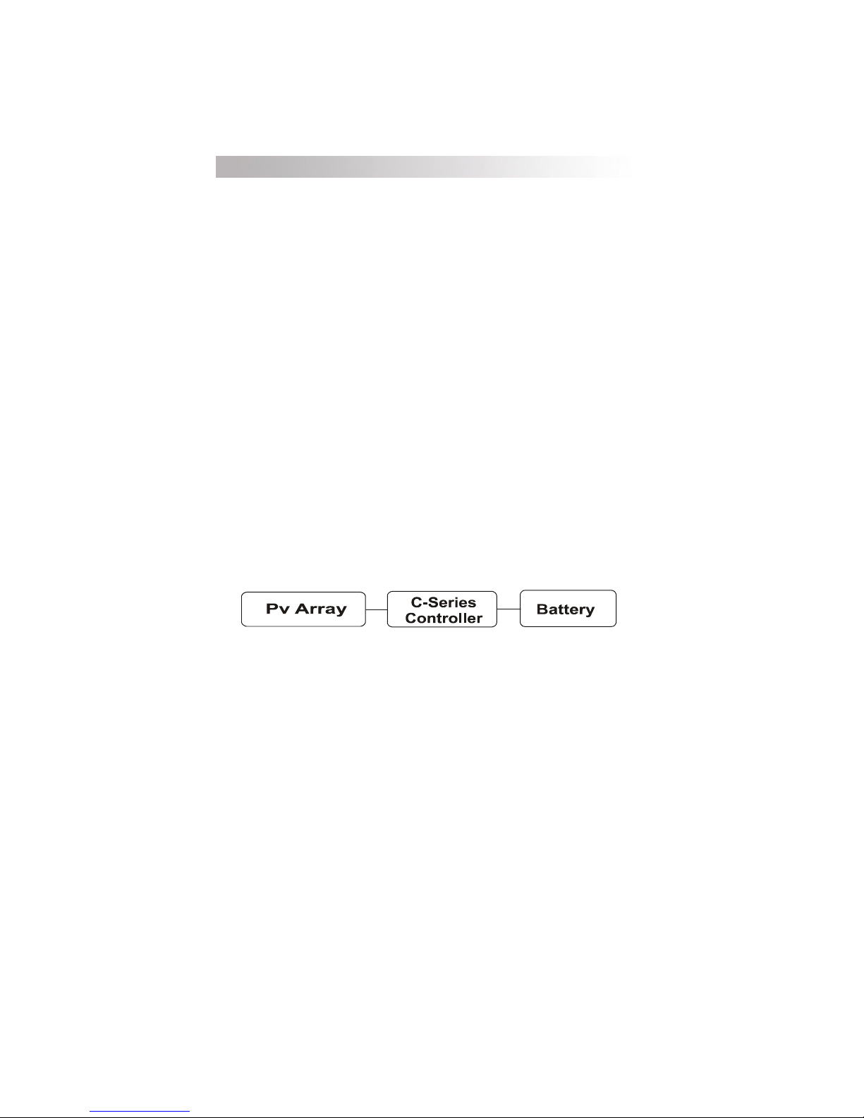
The C35/C40/C60 (C-Series) controllers are among the finest controllers
available and can be used with 12, 24, or 48 volt DC systems (depending upon
model) as PV charge controllers, DC diversion controllers, or DC load
controllers (low voltage disconnect). These capabilities make the C-Series the
only DC controllers youll need! Numerous standard features are provided to
maximize the performance of the system:
· Solid-state Pulse Width Modulated (PWM) charging process with three-
stage control, temperature compensation, and manual or automatic
equalization to maximizes system performance and increase battery life.
· Meets National Electrical Code (NEC) and other international controller
specifications.
· UL listed for the U.S. (UL Standard 1741 (draft) 1998), and Canada
(CSA-C22.2 No. 107.1-95).
· Electronic overload and short circuit protection with automatic and manual
reset capability increases the reliability of unattended systems by eliminating
blown fuses and tripped circuit breakers.
· Field adjustment of charge setpoints is provided by rotary controls with
removable knobs, reducing the potential for setpoint tampering. Calibrated
scales and test points allow precise adjustments of settings.
· Optional external battery temperature compensation sensor (BTS) for
automatic adjustment of charge setpoints (required by UL draft standard
1741 and strongly recommended for sealed batteries).
· Over-temperature protection for the electronic circuitry when used in hot
environments (over 113 °F/45 °C).
· Indoor-type, powder-coated enclosure for wall mounting.
· Multicolor LED with easy to read mode/status label.
· Optional LCD meter for remote or direct mounting on the controller. May be
mounted up to 1000 feet away.
· 2-year limited warranty.
©2000 Xantrex Technology Inc.
1
Page 8
1.0 INTRODUCTION
Operating Modes
The C-Series controller can operate as either a photovoltaic charge
controller, a diversion controller, or a DC load controller. The controller cannot
operate in more than one mode at the same time. If several modes are required
in a system, a dedicated controller must be used for each mode.
Photovoltaic Charge Control
When this mode is selected, the status LED will indicate either blinking
green or solid green. It will alternate red/green when in equalization mode.
Diversion Control Mode
When this mode is selected, the status LED will indicate either blinking
green or solid green.
DC Load Control Mode
When this mode is selected, the status LED will typically indicate blinking
red or solid red as the controller turns the DC loads OFF when battery
voltage is low.
Photovoltaic Charge Control Mode
Depending on the model, the controller can regulate up to 60 amps of
continuous photovoltaic (PV) array current at 12 or 24 volts (C60), or 12, 24 or
48volts DC (C40) for charging batteries. This rating includes the NEC required
deratings. When used in this mode, ensure that the operating mode jumper is
on the charge control pins. To enable the Photovoltaic Charge Control Mode,
see Configuring the CSeries in the installation section of this manual.
If the PV arrays output increases above the rated amp level due to
reflection or edge of cloud effect, the controller will continue to operate until the
heatsink reaches a maximum safe operating temperature. This will take several
minutes to occur depending upon the ambient temperature involved. When the
heatsink reaches the maximum safe temperature, the controller will reduce the
current, cooling the transistors and the heatsink.
If the current from the PV array reaches 85 amps, the controller will turn off
to protect the circuitry. In the event of a shutdown, the controller automatically
resets itself after 10 minutes (if overcurrent condition is no longer present).
The C-Series charge controller rapidly cycles the current source on-and-off
to control the charging current and voltage of the battery. This occurs in both the
charge control mode and the diversion control mode. The amount of time the
current source is connected to the battery is varied to control the average current
flow. This is often referred to as pulse width modulation (PWM) and allows the
current to be tapered, rather than coarsely turning the current off and on as with
relay type PV array charge controllers.
2
©2000 Xantrex Technology Inc.
Page 9
1.0 INTRODUCTION
Automatic PV Array Night Disconnect
At night, the PV array is automatically disconnected from the battery to
prevent reverse leakage of power. This eliminates the need for a blocking
diode between the battery and the PV array. If thin-film or amorphous solar
modules are being used, diodes may still be required to prevent damage from
partial shading conditions. Check the documentation provided with the PV
modules.
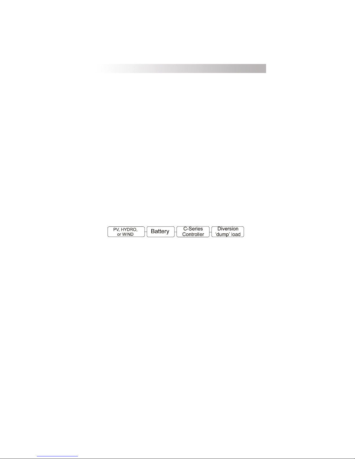
Diversion Control Mode
The C-Series can operate as a diversion control to manage battery charging
from alternative-energy sources such as wind or hydroelectric generators.
Systems utilizing solar arrays do not have a requirement for diversion loads since
a solar module can be open-circuited without damage. However, even with a
solar based system it may be desirable to use excess power to operate DC
loads. When used in this way, the C-Series controls a diversion load to redirect
the excess power generated instead of allowing it to flow into the battery. This
prevents damage to the charging source from an over-speed condition which
could occur if the charging source is suddenly disconnected from all loads as
series relay regulators do. Consult your dealer for load and regulator size
recommendations.
When the controller operates as a diversion regulator, it provides threestage regulation of battery voltage, with temperature compensation and automatic or manual equalization. See the Three-Stage Battery Charging section
for more information on this process.
Diversion mode requires a separate dump load to regulate the battery.
This load must be able to absorb more power than the charging source is able to
produce at its peak output, or the DC voltage will become unregulated. The
dump load must be available for the diversion of power at all times. Resistivetype heating elements are the best diversion loads. Special direct current
water heating elements are available. Light bulbs and motors are not recommended as diversion loads because they are unreliable.
When used in diversion mode, ensure that the operating mode jumpers are
on the charge control pins. See Configuring the CSeries in Section 3 of this
manual.
Current draw of the diversion load is very important. Problems may arise
from operating with a load that is too small or too large. A diversion load that is
too small will not be able to absorb all the excess power from the current source
once the batteries are full.
Diversion loads in excess of 85 amps are capable of absorbing more power
than the C-Series is designed to handle, resulting in an over-current shut down.
During this time, the unit will not regulate electrical flow in the system, and battery
damage may result.
A diversion load that draws about 25% more current than the charging
sources maximum output capability is usually suitable for use with the C-Series.
©2000 Xantrex Technology Inc.
3
Page 10
1.0 INTRODUCTION
DC Load Control Mode
The C-Series can also operate as a load control (also called a low voltage
disconnect) to manage the discharging of the battery. A load controller
prevents damage to the battery from over-discharge during periods of poor
weather or excessive loads.
Battery
When used in load control mode, ensure that the operating mode jumpers
are on the load control pins. See Configuring the C-Series section of this
booklet.
The controller delays disconnecting the DC loads for 6 minutes after the
voltage drops below the low voltage disconnect (LVD) setting. Loads are
either automatically or manually reconnected when battery voltage exceeds the
low-voltage reconnect (LVR) setting for 6 minutes. The EQUALIZE jumper
determines manual or automatic reconnect when the C-Series is used as a load
controller.
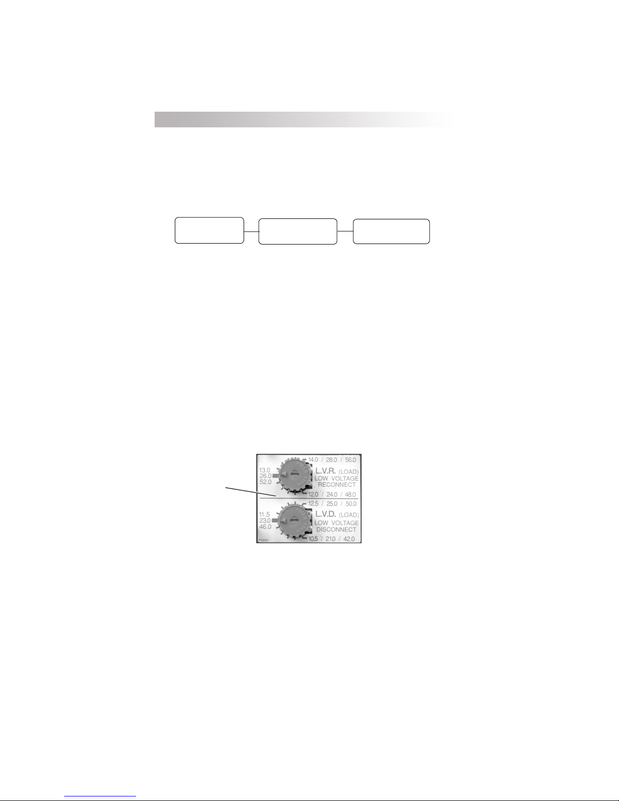
When used as a DC load controller, the settings of the LVR and LVD are
controlled by two rotary potentiometers on the circuit board. The scale on the
adjustment potentiometers differ from the scale used for other functions. A
decal with the appropriate adjustment scale is included with the C-Series and
shown below. Place this scale over the pots when using the C-Series as a
load controller. Do not temperature-compensate these settings. Do not install
the optional battery temperature compensation sensor.
Attach sticker over
potentiometers for
Load Control Settings
C-Series
Controller
DC Load
4
Sticker Displaying Load Control Voltage Settings
Figure 1
©2000 Xantrex Technology Inc.
Page 11

2.0 FEATURES
Features
The C-Series features include over-temperature protection, electronic over-
current protection, and automatic battery temperature compensation.
Over-Temperature Protection
The temperature of the controllers transistors is continuously monitored.
This protects the charge controller from damage in high temperature
environments. If excessive temperatures are detected while operating in
charge or diversion control mode, the controllers transistors are rapidly turned
off and on to reduce the charge rate. This will reduce the transistor
temperature.
As a load controller, the load is disconnected before the transistors reach
an excessive temperature. Once the temperature has dropped, the loads are
reconnected. When the over-temperature protection system has caused the
controller to shutdown, the status LED will be orange and will blink fast (about
once a second). This is the same indication shown during an over-current
condition.
Electronic Over-Current Protection
During operation, the C-Series controllers continuously monitor the current
flowing through it. If the current exceeds 85 amps, the transistor switches are
opened, stopping the flow of electricity. The detection circuitry is faster than
breakers or fuses, and they will not trip or blow when a fault occurs. When
the over-current protection system is activated, the status LED will indicate
orange and will blink fast (about once a second). This is the same indication as
produced by an over temperature condition.
The C-Series controllers automatically resets the over-current protection
system every 6 minutes. If an overload or short circuit is still present, the
controller will shut off and wait another 6 minutes. This will occur continuously
until the problem is corrected.
The reset switch on the right side of the controller allows the user to
manually reconnect the PV array or DC loads after an over-current condition
occurs. Hold the reset switch for 5 seconds to return to normal operation. If
the controller is unable to restart, check the wiring and reduce the loads
connected. There may be a delay after manually pressing the reset switch
before reconnecting the PV array.
The shunt used to measure the current flow in the C-Series is located in
the positive conductor of the circuit allowing greater flexibility in system
grounding. The negative terminals are all common to one another.
©2000 Xantrex Technology Inc.
5
Page 12
2.0 FEATURES
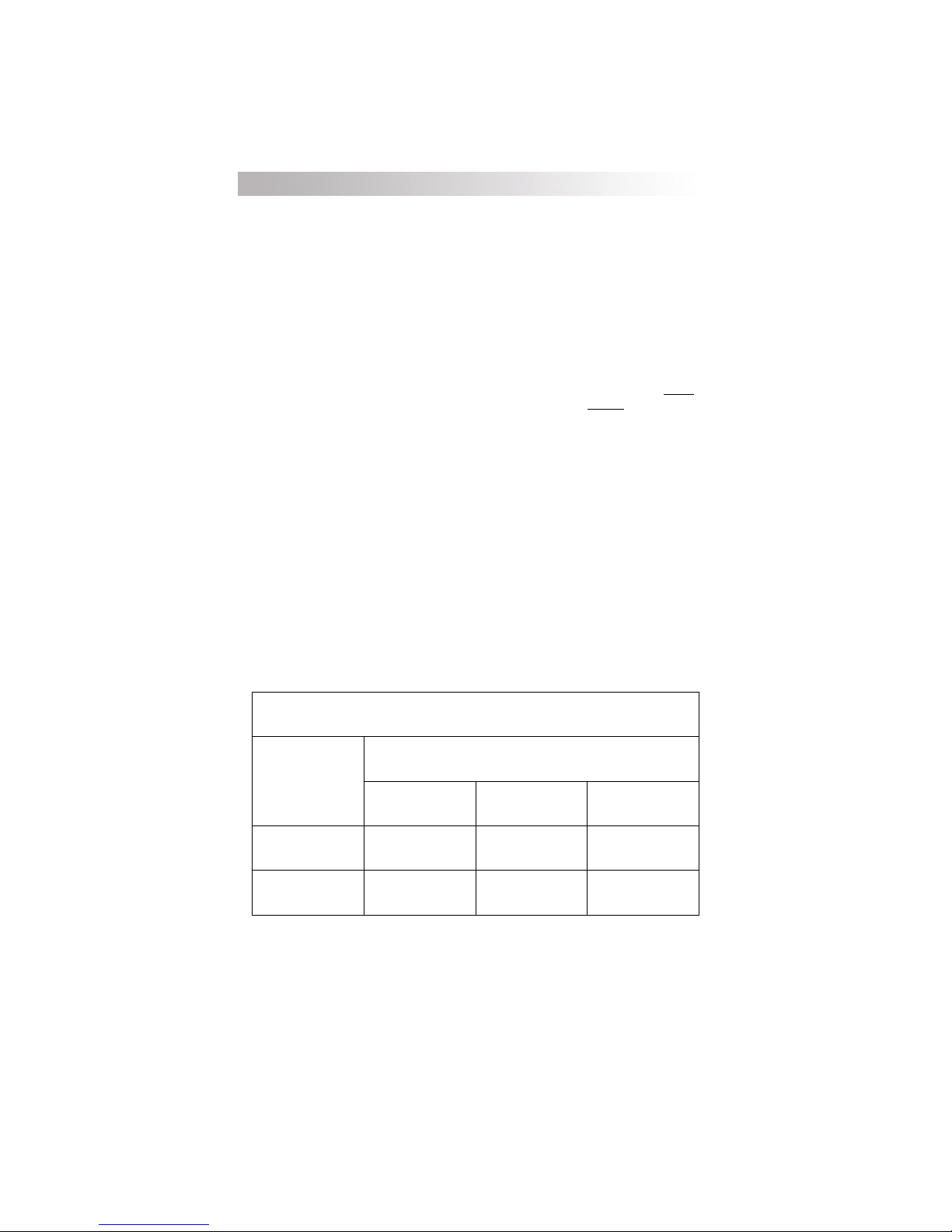
Battery Temperature Compensation
The optional plug-in external Battery Temperature Sensor (BTS)
automatically fine tunes the charging process of the C-Series. The BTS is
required by UL Standard 1741 and UL approval is based on its installation.
However, do not install the battery temperature sensor if you are using the
C-Series as a DC load controller. The BTS may be extended by using a
standard phone cable with RJ-11 plugs.
If the temperature sensor is installed, the regulation setpoints should be
adjusted for a battery at room temperature (2327 °C/7480 °F). The C-Series
adjusts the BULK and FLOAT setpoints 30 mV per degree Celsius for a
lead-acid type battery and 20 mV per degree Celsius for a
battery, as required per UL Standard 1741. For 24 and 48 volt systems, the
compensation is twice and four times the values listed respectively. See Table 1.
If the temperature sensor is NOT installed, the setpoints should be adjusted
for the temperature of the battery during operation. Seasonal adjustment of the
setpoints may be necessary to prevent battery damage and to ensure proper
charging. If the battery temperature sensor is installed, no seasonal adjustments
are required (see Temperature Compensation in this manual).
If the wiring to the sensor is damaged and the wires are shorted or cut, the
system will return to the non-temperature compensated settings.
Install the BTS on the side of the battery below the electrolyte level. It is
best to place the sensor between batteries and place the batteries in an insulated
box to reduce the influence of the ambient temperature outside the battery
enclosure. Ventilate the battery box at the highest point to prevent hydrogen
accumulation.
10-cell, NiCad type
6-cell,
TRAHCNOITASNEPMOCERUTAREPMETTNIOPTESREGRAHC
egatloVmetsyS
epyTyrettaB
CDV21CDV42CDV84
dicAdaeLC°/stlov030.0C°/stlov060.0C°/stlov021.0
daCiNC°/stlov020.0C°/stlov040.0C°/stlov080.0
Charger Setpoint Temperature Compensation
6
Table 1
©2000 Xantrex Technology Inc.
Page 13
2.0 FEATURES
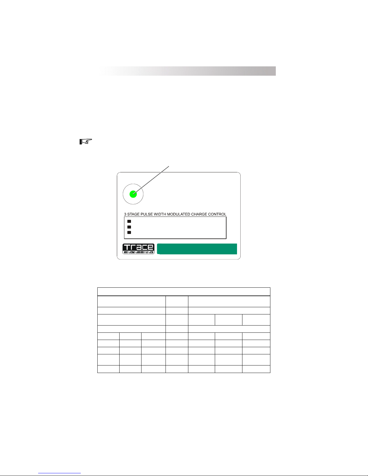
LED Status Indicator
A multi-color LED indicates the operating status of the controller. A colorcoded label is included on the cover of the controller explaining the status LEDs
operation. When the controller is in Charge Control mode, the LED will be
green. When in Load Control mode, the LED will be red. An orange LED
indicates an error or a load disconnect condition. When battery equalization is
in process, the LED alternates between red and green.
NOTE: The green and red color of the LED only indicates the particular
operating mode and the battery voltage level. It does not indicate whether the
charging source is functioning properly.
Multicolor LED Indicator
STATUS
C35
C40
C60
Green Blink Charge Control Mode
Green Solid Battery Charged
Red Blink Load Control Mode
Red Solid
Orange Blin k Slow Load Disconnected
Orange Blink Fas t
/
Green
Red
35 Amp Controller
40 Amp Controller
60 Amp Controller
Alternating - Equalization Enabled
Batte ry Dis c h arg ed
Overload/Overtemp
12/24 VDC
12/24/48 VDC
12/24 VDC
Charge / Load Controller
5916-195th STREET NE ARLINGTON WASHINGTON 98223 TELEPHONE(360)435-8826 FAX(360)435-2229
CSeries Front Panel Label
gnitteSTAOLFtayrettaB
gnitteSKLUBtayrettaB
)-(suniMgnitteSkluB )+(sulPgnitteSDVL
CDV52.0CDV05.0CDV00.1
CDV05.0CDV00.1CDV00.2
CDV57.0CDV05.1CDV00.3
57.0>
stlov21stlov42stlov84egatloVCDstlov21stlov42stlov84
05.1>
kluBwoleb
kluBwoleb
00.3>
Figure 1
)rotacidnIsutatSDELgnisU(EGATLOVYRETTAB
DEL
)edoMnoisreviD/egrahC(DELneerG
kluBwoleb
SUTATS
NOsyawlA
sknilB5
sknilB4
sknilB3
sknilB2
knilB1
51.0>
DVLevoba
CDV51.0CDV03.0CDV54.0
CDV03.0CDV06.0CDV09.0
CDV54.0CDV09.0CDV53.1
54.0>
DVLevoba
03.0>
DVLevoba
09.0>
DVLevoba
)edoMlortnoCdaoL(DELdeR
)DVL=setunim6rof(gnitteSDVLtayrettaB
54.0>
DVLevoba
53.1>
DVLevoba
©2000 Xantrex Technology Inc.
Battery Voltage LED Indications
Table 2
7
Page 14

2.0 FEATURES
Charge Control or Diversion Control Mode Indications
Solid Green
The battery is being charged in the FLOAT stage. The status LED remains
ON solid unless the batteries drop below the float voltage setting for an
accumulative period of one hour. This allows the user to confirm that the
system reached the float stage during the charging process when checked at
the end of the day. Reaching the float stage frequently is a good indication of
proper system operation and will maximize battery life and performance.
Blinking Green
The controller is in the CHARGE CONTROL or DIVERSION CONTROL
mode and the battery is not fully charged. As the battery voltage approaches
the BULK setting, the status LED will blink green several times (up to five) and
then pause, indicating the battery voltage is approaching the bulk setting and
provides an indication of the battery condition. Refer to Table 2 on the previous
page to determine the battery voltage.
NOTE: A single green flash indicates the battery is below the bulk voltage
setting. It does NOT indicate the batteries are charging.
Load Control Indications
Solid Red
The controller is in the DC LOAD CONTROL mode and the battery
voltage has reached the Low Voltage Disconnect (LVD) setting. After a
6-minute delay, DC loads will be disconnected unless the user reduces the
loads to a point that the battery voltage exceeds the LVD setting.
Blinking Red
As battery voltage approaches the LVD setting, the LED will blink red
several times (up to five) and then pause providing an indication of battery
voltage. Refer to Table 2 on the previous page to determine the battery voltage.
Slow Blinking Orange
The controller is in the DC LOAD CONTROL mode and has disconnected
the loads due to reaching the LVD setting. The user can press the reset switch for
a maximum 10-minute grace period, or can wait until the voltage rises above
the Low Voltage Reconnect (LVR) setting to allow an automatic reset to occur.
8
©2000 Xantrex Technology Inc.
Page 15

2.0 FEATURES
Equalization Mode Indication
Alternating Red and Green
The controller is in the EQUALIZE mode. It will automatically stop the
equalization process after accumulating two hours of operation at a voltage
above the BULK setting. The user can stop the equalization process at any time
by pressing the reset switch until the status LED stops alternating red and green.
Error Mode Indication
Fast Blinking Orange
The controller detected an over-current or an over-temperature condition
and the loads are disconnected. The controller will try to automatically restart
the loads after a 6-minute delay. If the controller will not restart, turn off all
loads and press the reset switch. If it then restarts, the loads may be too large.
A delay up to five seconds may occur before the controller attempts to restart
after pressing the reset switch.
©2000 Xantrex Technology Inc.
9
Page 16

3.0 INSTALLATION
Installation
The C-Series controllers are state-of-the-art precision electronic
instruments. Installation, environment, mounting, and wiring must be
accomplished in accordance with applicable local and national electrical codes.
The instructions that follow are applicable to the typical installation. For special
applications, consult a qualified electrician or your Trace dealer. Installation
procedures will vary according to your specific application.
Mounting
The C-Series controllers are designed for indoor mounting. Care should be
taken in selecting a location and when mounting the enclosure. Avoid mounting
it in direct sunlight in order to reduce heating of the enclosure and subsequent
high operating temperatures. The enclosure should be mounted vertically on
awall.
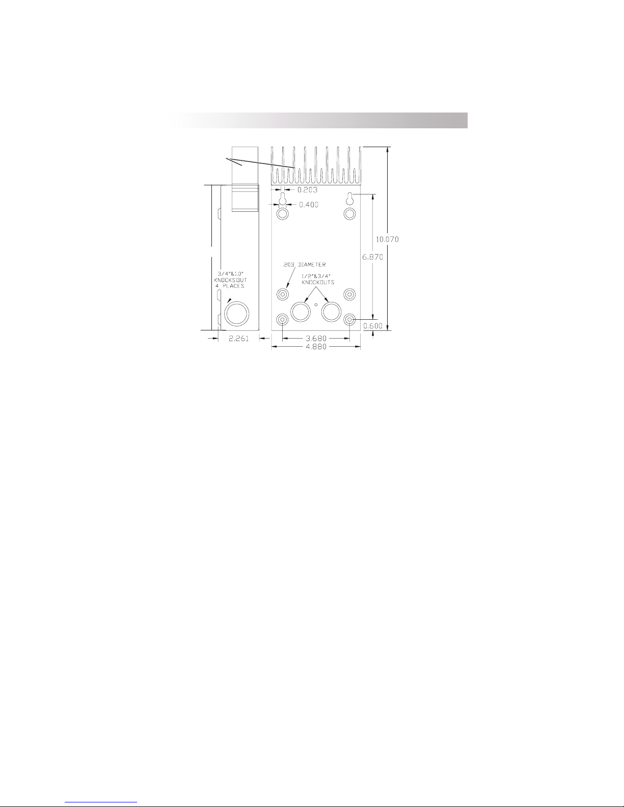
Mounting and enclosure dimensions are shown in Figure 2 (the C-35
controller does not feature an external heat sink). Remove the faceplate on the
controller and locate the upper two screw locations on the wall. The back of
the enclosure is provided with keyholes for mounting. Leave the screw heads
backed out approximately 1/4 inch (6 mm) or less. Place the controller onto the
screws and pull it down into the keyhole slots. Then insert the two lower
screws to lock the enclosure onto the wall. Provide either strain-relief clamps
or conduit to prevent damage to the circuit board and terminal block from pulling
on the wires. The cover should be replaced and retained with the screws
provided (#10-32 x 3/8" SMS).
In outdoor installations, the C-Series units must be installed in a rainproof
enclosure to eliminate exposure to rain or water-spray. The use of conformalcoated circuit boards, plated terminals, powder-coated metal components, and
stainless steel fasteners improves tolerance to hostile environments.
CAUTION: INSTALL THE C-SERIES CONTROLLER IN A DRY, PROTECTED
LOCATION AWAY FROM SOURCES OF HIGH TEMPERATURE, MOISTURE,
AND VIBRATION. EXPOSURE TO SALTWATER IS PARTICULARLY
DESTRUCTIVE. CORROSION OF THE CIRCUIT BOARD IS NOT COVERED BY
THE WARRANTY.
10
©2000 Xantrex Technology Inc.
Page 17
3.0 INSTALLATION
Heatsink not included
on C-35.
8
Figure 2
CSeries Dimensions
Do not locate the C-Series controller in a sealed compartment with the
batteries. Batteries can vent hydrogen sulfide gas, which is corrosive to
electronic equipment. Batteries also generate hydrogen and oxygen gas that
can explode when exposed to a spark.
If using sealed batteries, the controller can be mounted in the same
enclosure as long as it is adequately ventilated.
©2000 Xantrex Technology Inc.
11
Page 18

3.0 INSTALLATION
Wiring
Disconnect battery and PV sources before wiring. Set the voltage
selection jumper to the appropriate setting before energizing the system (see
User Configuration Options for instructions). Incorrect settings may result in
damage to the system as charging regulation will not occur. Torque the
terminals to 20 inch-pounds for 14-10 AWG (25 for 8 AWG, 35 for 6 AWG) once
the wires have been installed. Replace the cover.
12 Volt Position
24 Volt Position
48 Volt Position
(C40 only)
C40 C35 and C60
Figure 3
Voltage Selection Jumper
12 Volt Position
24 Volt Position
Battery Positive + PV +/Load +
Common Negatives
Figure 4
Battery Connection Terminals
NOTE: Regardless of configuration, only the positive conductor from a PV array
OR a DC load may be connected to the terminal marked PV POS/LOAD.
12
©2000 Xantrex Technology Inc.
Page 19

3.0 INSTALLATION
Minimum Recommended Wire Size
The minimum recommended wire gauge is #8 AWG (for C35 and C40) with
a 75 °C insulation rating and #6 AWG, 90 °C wire for the C60. The terminals on
the C-Series will accept up to #2 AWG (33.6 mm
however, UL specifications only allow the use of up to #6 AWG (13.3 mm
maximum. No crimp-on terminals or lugs are required.
Each model of the CSeries controller is rated for a maximum continuous
current of 35, 40 or 60 amps. Since PV outputs can vary due to the array size
or sunlight striking it, the safe minimum wire size should be based on the
maximum current ratings. The NEC requires conductors and over-current
devices be operated at no more than 80% of their rating. Refer to Table 3
below for a listing of the minimum wire size to use for each model.
2
) copper or aluminum wire,
2
)
RELLORTNOCEZISERIWMUMINIM
53CGWA8#spma54
04CGWA8#spma05
*06C)eriwC°09(GWA6#)ytud%001detsil(spma06
**06C)eriwC°57(GWA4#)ytud%001detsil(spma06
GNITAR
ECIVEDTNERRUC-REVO
Table 3
Minimum Wire Size
NOTE: *To meet UL requirements, use #6 AWG, 90 °C wire and a 60 amp LISTED
100% DUTY over-current device for the C60 controller.
** Not approved by UL for direct connection into the controller. Use a splicer
block as specified below and #6 AWG (90 °C wire) to connect to the
controllerterminals.
If there is a significant distance between the PV array and the controller
and/or the controller and the battery, larger wires can be used to reduce the
voltage drop and improve performance. Refer to Table 4.
To use a larger size wire, use a splicer block (terminal block) intended for
this purpose. This allows the larger cable size from the batteries to be
spliced to the smaller wire size connected to the controller. Split-bolt kerneys
can also be used for wire splices. Follow manufactures recommendations for
torque and mounting (if required). Splicer blocks and split-bolt kerneys are
available from alternative energy suppliers.
©2000 Xantrex Technology Inc.
13
Page 20

3.0 INSTALLATION
Maximum One-way Distance and Wire Size
NOTE: NEC article 690 and local electrical codes should be consulted for wire
sizing and any additional installation requirements. For a C60 use a 60 amp,
100% Continuous Duty breaker and #6 AWG, 90 °C wire. Larger wire sizes
may be used to improve performance, but are NOT approved by UL to be
installed in the controller (use a splicer block as previously described on
page13 of this manual). Match the breaker to the wire if using larger
gaugewire.
Refer to Table 4 and find your maximum current in the left column, and the
one way distance from your power source (feet/meters) to the C-Series controller
(or the distance from the C-Series controller to your load) on the same line, then
read the wire size required at the top of the column.
The wiring, over-current protection devices (fuses and circuit breakers) and
installation methods used must conform to all national and local electrical codes
requirements.
Wiring should be protected from physical damage with conduit or a strain
relief clamp. You should pull the temperature sensor cable through the conduit
first as the connector may not fit if other wires have been pulled first.
As a minimum, a 60 amp DC rated current limiting fuse or circuit breaker
should be provided near the battery for protection from short circuits. To meet
NEC requirements, use a 60 amp circuit breaker listed for 100% duty for the C60.
To meet UL requirements, use #6 AWG copper wires rated for 90 °C for the C60.
14
©2000 Xantrex Technology Inc.
Page 21

3.0 INSTALLATION
nwohSnoitacilppACDV21
)sretem(teeFniecnatsiD )sretem(teeFniecnatsiD
GWA21GWA01GWA8GWA6
spmA
.tf8.8
.tf41
01
21
41
61
81
02
52
03
53
04
54
05
06
)m86.2(
.tf3.7
)m32.2(
.tf3.6
)m29.1(
.tf5.5
)m86.1(
.tf9.4
)m94.1(
.tf4.4
)m43.1(
.tf2.22
)m72.4(
)m77.6(
.tf6.11
.tf5.81
)m45.3(
)m46.5(
.tf01
.tf9.51
)m50.3(
)m58.4(
.tf7.8
.tf9.31
)m44.2(
)m42.4(
.tf8.7
.tf4.21
)m83.2(
)m87.3(
.tf7
.tf1.11
)m31.2(
)m83.3(
.tf6.5
.tf9.8
)m17.1(
)m17.2(
.tf7.4
.tf4.7
)m34.1(
)m62.2(
.tf4.6
)m59.1(
.tf6.5
)m17.1(
GWA4 GWA3 GWA2 GWA1 GWA0/1 GWA0/2
.tf1.65
.tf3.53
)m67.01(
.tf4.92
)m69.8(
.tf2.52
)m86.7(
.tf1.22
)m47.6(
.tf6.91
)m79.5(
.tf6.71
)m63.5(
.tf1.41
)m03.4(
.tf8.11
)m95.3(
.tf1.01
)m80.3(
.tf8.8
)m86.2(
.tf8.7
)m83.2(
.tf1.7
)m61.2(
.tf3.6
)m29.1(
.tf9.07
)m90.71(
)m86.2(
.tf7.64
.tf1.95
)m32.41(
)m16.12(
.tf1.04
.tf6.05
)m22.21(
)m24.51(
.tf0.53
.tf3.44
)m76.01(
)m05.31(
.tf2.13
.tf4.93
)m15.9(
)m10.21(
.tf0.82
.tf4.53
)m35.8(
)m97.01(
.tf4.22
.tf3.82
)m38.6(
)m36.8(
.tf7.81
.tf6.32
)m76.5(
)m91.7(
.tf0.61
.tf2.02
)m88.4(
)m61.6(
.tf0.41
.tf7.71
)m72.4(
)m86.2(
.tf5.21
.tf7.51
)m18.3(
)m97.4(
.tf2.11
.tf2.41
)m14.3(
)m33.4(
.tf3.9
.tf8.11
)m38.2(
)m06.3(
pordegatloV%3<arofecnatsiDeriWyaw-enOmumixaM
2ybecnatsidylpitluM,smetsySCDV42roF
4ybecnatsidylpitluM,smetsySCDV84roF
noitacificepseziseriw
.tf6.98
.tf5.211
)m13.72(
)m92.43(
.tf6.47
.tf7.39
)m47.22(
)m65.82(
.tf0.46
.tf4.08
)m15.91(
)m93.42(
.tf0.65
.tf3.07
)m70.71(
)m34.12(
.tf8.94
.tf5.26
)m81.51(
)m50.91(
.tf8.44
.tf2.65
)m66.31(
)m31.71(
.tf8.53
.tf0.54
)m19.01(
)m86.2(
.tf9.92
.tf5.73
)m11.9(
)m7.31(
.tf6.52
.tf1.23
)m08.7(
)m87.9(
.tf4.22
.tf1.82
)m38.6(
)m65.8(
.tf9.91
.tf0.52
)m70.6(
)m26.7(
.tf9.71
.tf5.22
)m64.5(
)m68.6(
.tf9.41
.tf7.81
)m45.4(
)m7.5(
mumixamriehtsdeecxetisaLUybdevorppatoneraseziSeriWesehT
.tf7.141
.tf8.522
)m91.34(
)m28.86(
.tf1.811
.tf2.881
)m00.63(
)m63.75(
.tf2.101
.tf3.161
)m58.03(
)m61.94(
.tf6.88
.tf2.141
)m10.72(
)m40.34(
.tf7.87
.tf5.521
)m99.32(
)m52.83(
.tf9.07
.tf9.211
)m16.12(
)m14.43(
.tf7.65
.tf3.09
)m82.71(
)m25.72(
.tf2.74
.tf3.57
)m93.41(
)m59.22(
.tf5.04
.tf5.46
)m43.21(
)m66.91(
.tf4.53
.tf5.65
)m97.01(
)m22.71(
.tf5.13
.tf2.05
)m06.9(
)m03.51(
.tf3.82
.tf2.54
)m36.8(
)m87.31(
.tf6.32
.tf6.73
)m91.7(
)m5.11(
One-way Wire Distance and Wire Size
©2000 Xantrex Technology Inc.
Table 4
15
Page 22

3.0 INSTALLATION
PV Charge Control Mode Cabling
Photovoltaic arrays generate current whenever light strikes the surface of
the array. Before connecting the C-Series controller, cover or disconnect the
array to prevent any current from being generated.
· Remove one or more of the knockout plugs on the controllers case and
feed the connecting wires through it.
· Connect the PV arrays positive (+) output to the terminal marked PV POS/
LOAD at the bottom of C-Seriess circuit board and tighten the lugs.
· Connect the PV arrays negative () output to the terminal marked
COMMON NEGATIVES and tighten the lugs.
· Connect the battery positive (+) cable to the terminal marked BAT POS and
tighten the lugs.
· Connect the negative () battery cable to the terminal marked COMMON
NEGATIVES and tighten the lugs.
· Secure the cabling with strain reliefs after allowing a little slack inside the
case to prevent damage to the controllers circuit board.
Battery Positive +
16
PV Array Positive +
Figure 5
PV Charge Control Mode Wiring
©2000 Xantrex Technology Inc.
Battery Negative PV Array Negative
Page 23

PV Array
Circuit Breaker
PV +
CONTROLLER
PV CHARGE CONTROL
BATTERY
POSITIVE +
PV +/
LOAD +
MODE
PV -
BATTERY +
Circuit Breaker
3.0 INSTALLATION
COMMON
NEGATIVES
BATTERY -
PV Charge Control Wiring Diagram
©2000 Xantrex Technology Inc.
–+
BATTERY
3553-W01-00A
Figure 6
17
Page 24

3.0 INSTALLATION
Diversion Control Mode Cabling
When using the C-Series unit as a diversion or DC load controller, the DC
load needs to be connected to the controller terminals marked as PV POS/LOAD
and COMMON NEGATIVE. The common negatives can be reversed or wired
with an appropriately sized single conductor to a more convenient location
such as a DC load center negative bus.
· Connect your DC current source (PV, wind, hydro, etc.) directly to
abattery.
· Connect an appropriately-sized cable from the positive battery terminal to
the controller terminal marked BAT POS.
· Connect a cable from the negative battery terminal to the terminal marked
COMMON NEGATIVES on the controllers circuit board.
· Connect a cable from the controllers terminal marked PV POS/LOAD to the
positive terminal of your DC diversion load.
· Connect a cable from the controllers terminal marked COMMON NEGA-
TIVES to the negative terminal of your DC diversion load.
· Tighten the terminal lugs to 20 inch-pounds for #14-10 AWG (25 for
#8 AWG, 35 for #6 AWG). Allow a little slack on the cables within the
controller and secure the wiring with strain reliefs.
NOTE: Do not use light bulbs for diversion loads. Use only resistive loads such
as air- or water-cooled heating elements.
Battery Positive + Battery Negative Diversion Load
18
Positive +
Diversion Load
Negative
Figure 7
PV Load Diversion Wiring
©2000 Xantrex Technology Inc.
Page 25

PV Array
CONTROLLER
LOAD DIVERSION MODE
BATTERY
POSITIVE +
PV +/
LOAD +
NEGATIVES
DIVERSION
LOAD
BATTERY +
3.0 INSTALLATION
COMMON
BATTERY -
PV +
Circuit Breaker
Load Diversion Wiring Diagram
©2000 Xantrex Technology Inc.
Circuit Breaker
–+
BATTERY
PV -
3553-W02-00A
Figure 8
19
Page 26

3.0 INSTALLATION
DC Load Control Mode Cabling
· Connect the positive battery cable to the terminal marked BAT POSITIVE
on the controller.
· Connect the negative battery cable to the terminal marked COMMON
NEGATIVES.
· Connect a cable between the PV POS/LOAD terminal on the controller and
the positive terminal on the DC load.
· Connect a cable between the controllers COMMON NEGATIVES terminal
and to the negative terminal of the load.
Battery Positive + Battery Negative DC Load Positive + DC Load Negative
Figure 9
Load Control Wiring
20
©2000 Xantrex Technology Inc.
Page 27

CONTROLLER
DC LOAD CONTROL MODE
BATTERY
POSITIVE +
PV +/
LOAD +
COMMON
NEGATIVES
3.0 INSTALLATION
BATTERY -
BATTERY +
Circuit Breaker
Load Control Wiring Diagram
LOAD -
Circuit Breaker
LOAD +
BATTERY
Figure 10
_
DC LOAD
+
–+
3553-W03-00A
©2000 Xantrex Technology Inc.
21
Page 28

3.0 INSTALLATION
Grounding
The C-series controllers are designed to work with both negative ground
and ungrounded electrical systems. The metal chassis of this charge/load
controller must be grounded for either system by connecting it with a copper wire
to a grounding electrode such as a ground rod driven into the earth.
If a negative ground system is desired, connect the negative current
carrying conductor to the grounding system at one point in the system. Consult
local and national electrical codes for more information and any additional
requirements.
22
©2000 Xantrex Technology Inc.
Page 29

3.0 INSTALLATION
Configuring the C-Series
Three sets of jumpers are located on the right side of the controllers
circuit board. These jumpers control equalization, low voltage reconnect,
battery voltage, and operating modes. They must be set correctly for the unit to
operate to its maximum potential.
Figure 11
Jumpers
The C-Series controllers are equipped with several of these jumpers.
Each are discussed in the appropriate section of this manual. The factory
default settings are shown below.
04C06C,53C
Factory Default Settings for C-Series Controllers
©2000 Xantrex Technology Inc.
egatloVyrettaB
RVL/ezilauqE
edoMgnitarepO
CDstlov21CDstlov21
launaM
noitazilauqE
lortnoCegrahClortnoCegrahC
launaM
noitazilauqE
Table 5
23
Page 30

3.0 INSTALLATION
NICAD SETTING
SELECTION RESISTOR
EQ/LVR JUMPER
CHARGE/LOAD
CONTROL JUMPER
RESET SWITCH
24
Configuration Jumpers Location
Figure 12
©2000 Xantrex Technology Inc.
SYSTEM VOLTAGE
JUMPER
Page 31

3.0 INSTALLATION
Automatic/Manual Battery Equalization (EQ) and Low
Voltage Reconnect (LVR)
Enables automatic or manual battery equalization in Charge Control mode,
and automatic or manual reconnect in the event of low voltage at the BAT POS
terminal in Load Control mode. When AUTO is enabled in Load Control mode,
the unit will reconnect automatically when voltage at the BATTERY POSITIVE
terminal exceeds the LVR setting. Factory setting is manual equalization and
manual reconnect.
12 Volt Position
24 Volt Position
48 Volt Position
C40 C35 and C60
12 Volt Position
24 Volt Position
Figure 13
Voltage Selection Jumper
Operating Mode
This jumper determines the operating mode: PV Charge Control and
Diversion Control mode, or Load Control mode. Factory setting is Charge
Control mode.
Figure 14
Operating Mode Jumper
Reset Switch
Press and hold to manually initiate or suspend battery equalization in
Charge Control mode. Press and release to reset following an error condition.
Press and release to reconnect following a low-voltage disconnect event. If
voltage remains below the LVD setting, the unit will disconnect after a 6-minute
grace period.
Figure 15
Reset Switch Jumper
©2000 Xantrex Technology Inc.
25
Page 32

3.0 INSTALLATION
Voltage
This jumper determines the voltage of the system that the controller will be
used with. Connect the two pins adjacent to the legend for the voltage of your
system: 12, 24, 48. Factory setting is 12 volts for the C35, C40 and C60. The
maximum DC voltage allowed is 125 VDC for a C40, and 55 VDC for the C35
and C60.
If the optional LCD meter (DVM/C40 or CM/R) is attached to the C-Series
controller, be sure to set the jumper on the back of it for the appropriate system
voltage. The jumper for limiting power consumption and dimming the CM display
is also located on the back of the LCD Displays.
12 Volt Position
24 Volt Position
48 Volt Position
C40 C35 and C60
Figure 16
Voltage Selection Jumper
12 Volt Position
24 Volt Position
26
©2000 Xantrex Technology Inc.
Page 33

3.0 INSTALLATION
Adjusting the C-Series
The charging rate and voltage reconnect/disconnect setting of the controller
are adjustable via two rotary potentiometer controls. The knobs are removable
to reduce the likelihood of tampering with the settings. Calibrated scales are
provided to allow setting of the control without requiring the use of a digital
voltmeter. Visual adjustment allows an accuracy of ± 0.1 volts.
Setting Voltage Parameters
In Charge Control mode, you can adjust the bulk and float charging voltage
by adjusting the potentiometers (pots) located in the bottom center of the
controllers circuit board (for more information regarding bulk and float charging
rates, see the Three-Stage Battery Charging Process section of this manual).
The potentiometer scale for bulk charge voltage is calibrated from 13.0 to
15.0volts (when the voltage jumper is set for a 12 volt system) in increments
of 0.2volts, from 26.0 to 30.0 volts (24 volt system) in increments of 0.4 volts,
or from 52.0 to 60.0 volts (48 volt system) in increments of 0.8 volts. For float
charge voltage, the potentiometer scale is calibrated from 12.5 to 14.5 volts
(12volt system), 25.0 to 29.0 volts (24 volt system), and from 50.0 to 58.0 volts
(48 volt system) with the same increments as above.
BULK and FLOAT Voltage Adjustment Potentiometers
©2000 Xantrex Technology Inc.
Charge/Diversion Control Mode
Figure 17
27
Page 34

3.0 INSTALLATION
Testpoints for Voltage Settings
At midrange on these scales, a testpoint is provided for use with a DC
digital voltmeter for assuring more accurate adjustment. The pots are equipped
with removable knobs to prevent accidental adjustments by the curious or
uninformed. If the knobs are missing, a 5/64" hex-head driver can be used to
adjust the settings. A digital voltmeter can be connected from the COMMON
NEGATIVE terminal on the circuit board and the small testpoint located to the left
of each adjustment pot at the nine oclock position. The testpoint provides a
reading from 0 to 2 volts; this value must be added to the lower value of the
adjustment range (Bulk=13.0, Float=12.5, LVR=12.0, LVD=10.5). Multiply this
value by 2 for 24 V and by 4 for 48 V.
For example, to set the bulk voltage to 14.4 volts, adjust the potentiometer
until the DVM displays 1.4 volts (13.0 V + 1.4 V = 14.4 V). To set bulk to 28.2,
adjust the pot until the DVM displays 1.10 volts (1.10 x 2 [24 volt] = 2.2 + 26.0 =
28.2). When using NiCad type batteries, add another 2 (12-volt), 4 (24-volt) or 8
(48-volts) to the settings.
TESTPOINTS
for DC multimeter
(center legs of potentiometer)
Connect the negative lead of
DVM to the COMMON
NEGATIVE terminal
DC Testpoints for Bulk and Float
Figure 18
If you are using the unit as a DC load controller, be sure to set the
potentiometers as shown in the DC Load Control section of this manual. The
upper knobs settings are reduced by 1 volt, resulting in a range of 14.0 VDC to
12.0 VDC (for a 12-volt system). The lower knobs settings are reduced by
2volts, resulting a range of 12.5 to 10.5 VDC (for a 12-volt system).
Load Control Mode (sticker)
Figure 19
DC Load Control Adjustment Sticker
28
©2000 Xantrex Technology Inc.
Page 35

3.0 INSTALLATION
Equalization
CAUTION: DO NOT EQUALIZE GEL OR SEALED TYPE BATTERIES!
The C-Series offers either manual or automatic triggering of the equalization
process (the default setting is manual). Automatic equalization is enabled by
moving the jumper located on the right side of the circuit board above the reset
switch. When automatic has been selected, an equalization charge will occur
every 30 days (holding the voltage 1 volt for 12-volt systems, 2 volts for 24-volt
systems, and 4 volts for 48-volt systems, above the bulk setting for 2 hours).
During the equalization process the status LED indicates equalization by
alternately blinking green and red. (Equalization is not recommended for NiCad
batteries and is disabled when the R46 resistor is cut).
Auto Equalize
Manual Equalize
Manual Equalize Jumper
Setting
Equalization Settings
Figure 20
Manual Equalize Switch
(when in Manual mode)
R46Cut for NiCad
applications
©2000 Xantrex Technology Inc.
Figure 21
Equalization Settings
29
Page 36

3.0 INSTALLATION
Manual Equalization
Manual equalization of the battery can be enabled by pressing the reset
switch on the right side of the C-Series for 10 seconds. The status LED
indicator will begin to alternate between red and green once equalization is
enabled. The equalization process will continue until the batteries have been
held at or above the bulk setting for two hours of accumulated time. During the
equalization process, the battery voltage will be limited to 1volt above the bulk
setting for 12-volt systems (2 volts for 24-volt systems, and 4 volts for 48-volt
systems). Once the battery voltage has been at or above the bulk setting for a
cumulative period of two hours, the C-Series will return to the float stage of the
charging process.
Front Panel LED
(flashes red/green
during Equalization)
Reset Switch Access
Figure 22
C40 Front and Side Panel
To stop the equalization process, press the reset switch. The status LED
will stop alternating between red and green. If the equalization process was
shorter than one hour, the controller will continue with a bulk charge cycle and
then hold the battery at the bulk setting for one hour (the absorption stage) before
returning to the float setting.
During the equalization process the status LED will alternate between red
and green and will not provide any other mode/status indication. Large battery
banks may need several equalization cycles to fully stir the electrolyte and charge
the cells. These cycles should follow one another until the battery voltage
reaches the upper limit for the full two hours.
30
©2000 Xantrex Technology Inc.
Page 37

3.0 INSTALLATION
Automatic Equalization
CAUTION: DO NOT EQUALIZE GEL OR SEALED TYPE BATTERIES!
The C-Series controllers can automatically trigger an equalization charge
every 30 days. The status LED will indicate that the equalization process is
occurring. The equalization process will continue until the voltage has been
held above the bulk setting for a cumulative period of two hours. This might
take several days on larger systems with big batteries and small PV arrays.
The battery voltage only needs to exceed the bulk setting for the timer to start
countingthe voltage may not reach the equalization voltage setting.
To enable automatic equalization, the jumper located on the right side of the
circuit board must be moved to the AUTO setting. The default setting of the
C-Series controllers is for manual equalization. To disable the automatic
equalization system, move the equalize jumper.
To manually stop the equalization process, press the reset switch on the
right side of the unit until the status LED stops alternating between red and
green. If the equalization process was shorter than one hour, the controller will
continue with a bulk charge cycle and then hold the battery at the bulk setting for
one hour (the absorption stage) before returning to the float setting. Once a
manual equalization has been triggered, the 30-day period to the next automatic
equalization will be restarted. To prevent automatic equalization, move the
equalize jumper to the manual position.
Manual Equalize Jumper
Setting
Equalize Jumper and Reset Switch
©2000 Xantrex Technology Inc.
Auto Equalize
Manual Equalize
Manual Equalize/Reset Switch
Figure 23
31
Page 38

3.0 INSTALLATION
Temperature Compensation
If a Battery Temperature Sensor (BTS) is installed, the charge controlling
process will be automatically adjusted for the battery temperature. Set bulk and
float voltage for a battery at normal room temperature 7480 °F (2327 °C).
Actual voltage may vary above or below these settings due to adjustment for
battery temperature.
If no Battery Temperature Sensor (BTS) is installed and the batteries will be
operating in very hot or very cold conditions, adjust the bulk and float settings to
allow for the battery temperature. The recommended adjustments can be
found in the table below. The setting should be lowered for ambient
temperatures above 80 °F (27 °C) and raised for ambient temperature below
75°F (23 °C). If significant seasonal variations are common, you will have to
change the settings several times a year to prevent battery damage and ensure
proper operation.
NOTE: Do NOT compensate the settings when using the C-Series controller as
a DC load controller.
TRAHCNOITASNEPMOCERUTAREPMETTNIOPTESREGRAHC
egatloVmetsyS
epyTyrettaB
CDV21CDV42CDV84
dicAdaeLC°/stlov030.0C°/stlov060.0C°/stlov021.0
daCiNC°/stlov020.0C°/stlov040.0C°/stlov080.0
Temperature Compensation
Temperature compensation is based on battery type: 5 mV/cell for lead
acid type batteries and 2 mV/cell for alkaline type batteries (NiCad or NiFe).
32
Table 6
©2000 Xantrex Technology Inc.
Page 39

3.0 INSTALLATION
Setting LVR and LVD (Load Control Mode)
To change the low voltage disconnect (LVD) and low voltage reconnect
(LVR) settings, use the same BULK and FLOAT potentiometers.
When the C-Series is wired for DC Load Control mode, the potentiometers
scale calibration is altered from what is printed on the circuit board. A sticker
is provided with the C-Series with the proper scale calibrations for the Load
Control mode. The BULK potentiometer becomes the Low Voltage Reconnect
(LVR), and the FLOAT potentiometer becomes the Low Voltage Disconnect
(LVD). Place the sticker provided over the potentiometers. The knobs may
have to be removed for sticker placement, then reinstalled. The sticker is
packed inside the C-Series (bottom of unit).
DC Load Control Adjustment Sticker
Figure 24
If the sticker is lost, follow these instructions for voltage calibration using the
scale printed on the C-Series circuit board.
From the scale shown on the circuit board for the LVR setting (BULK
setting when in Charge Control mode), subtract 1 volt for 12-volt systems,
2volts (for 24-volt systems), and 4volts (for 48-volt systems).
From the scale shown for the LVD setting (FLOAT setting in Charge
Control mode), subtract 2 volts for the 12-volt system, 4 volts for a 24-volt
system, and 8 volts for a 48-volt system.
Subtract the proper voltages
from the values printed on the
circuit board, if the sticker is
missing
Figure 25
DC Load Control Adjustment Sticker
MANUAL reconnect of the loads is allowed when voltage has not exceeded
the LVR setting. To reconnect the loads, press the reset button on the right
side of the unit. If the voltage is below the LVR level, the DC load can be
reconnected for approximately 6 minutes. Multiple reconnects are allowed, but
the on time duration will vary with battery voltage. The EQUALIZE jumper
allows the controller to be set for AUTO reconnect of the dc load when the
voltage exceeds the LVR setting.
NOTE: The LED will light red only in Load Control mode; never in Charge or
Diversion mode (unless it is reversed upon reinstallation).
©2000 Xantrex Technology Inc.
33
Page 40

3.0 INSTALLATION
Setting Diversion Control Mode
When the C-Series controller is configured for Diversion Control mode, you
can set the voltage at which the unit begins diverting current (high voltage
diversion). The unit will continue diverting excess current to the diversion load
until the source voltage falls to the Bulk setting. After two hours at the Bulk
setting, the unit will reduce the battery charging voltage to the Float voltage
setting. This will usually result in more current being diverted to the diversion
load.
The flashing rate of the LED indicates the battery state of charge. Solid
green indicates the battery is fully charged (float mode). Five flashes indicates
the battery is in Bulk mode. As the flashing rate decreases, the battery is
discharged to a lower voltage level (i.e., somewhere below the Bulk voltage
setting). Table 7 indicates the approximate level the battery is below the Bulk
voltage setting.
As an example, if the system battery voltage is 24 volts and the internal
Bulk voltage setting is set for 26 volts, you can calculate approximately how much
below the Bulk setting the batteries are by subtracting the number in Table7
from 26 (the internal Bulk setting). With the LED indicating two blinks, the
battery voltage is approximately 24.5 volts (26 volts Bulk setting minus
1.50volts in the table). With the LED indicating one blink, the battery voltage
is
somewhere below the 24.5 volts, indicating the battery may be seriously
damaged.
NOTE: The LED will light green only in Diversion and Charge Control mode
(unless it is reinstalled backwards).
34
)rotacidnIsutatSDELgnisU(EGATLOVYRETTAB
DEL
)edoMnoisreviD/egrahC(DELneerG
gnitteSTAOLFtayrettaB
gnitteSKLUBtayrettaB
)-(suniMgnitteSkluB )+(sulPgnitteSDVL
CDV52.0CDV05.0CDV00.1
CDV05.0CDV00.1CDV00.2
CDV57.0CDV05.1CDV00.3
57.0>
stlov21stlov42stlov84egatloVCDstlov21stlov42stlov84
05.1>
kluBwoleb
kluBwoleb
00.3>
kluBwoleb
SUTATS
NOsyawlA
sknilB5
sknilB4
sknilB3
sknilB2
knilB1
51.0>
DVLevoba
CDV51.0CDV03.0CDV54.0
CDV03.0CDV06.0CDV09.0
CDV54.0CDV09.0CDV53.1
54.0>
DVLevoba
03.0>
DVLevoba
09.0>
DVLevoba
Table 7
Battery Voltage LED Indications
©2000 Xantrex Technology Inc.
)edoMlortnoCdaoL(DELdeR
)DVL=setunim6rof(gnitteSDVLtayrettaB
54.0>
DVLevoba
53.1>
DVLevoba
Page 41

4.0 OPTIONS
C-Series LCD Meter Displays
Two optional LCD digital meter displays are available for the C-Series
controllers; the DVM/C40 replaces the standard faceplate on the C-Series
controller and the CMR/50 or CMR/100 mounts remotely. The remote version is
available with either 50 foot or 100 foot cables. Longer runs may be possible
(up to 1000 ft/305m) because the communication is a serial-data type link.
These displays include a two-line, 32-character LCD and a status LED
indicator.
The LCD displays provide the following information:
· PV Array or DC load pass-through current: 0 to 85 amps DC
· Battery voltage: 4 to 100 volts DC
· Watts: 0 to 3600 watts (volts times amps)
· Amp-hours: 0 to 65536 Ah; can be reset to 0
· Totalizing amp-hours: 0 to 65536 Ah; resets to zero when power is
disconnected
· Status LED: green, red, or orange
If the C-Series controller is disconnected from the battery or the meter
cable, the meter will be reset when it is powered up. Press and hold the pushbutton on the front of the meter to manually reset the amp-hour meter. Press and
release this button to turn the backlight on or off. An adjustable potentiometer
on the back of the meter enables you to adjust the contrast of the LCD display.
When installing the meter, be sure to set the jumper on the printed circuit board
over the pin set to match the controller board for the system voltage, either 12,
24, or 48 volts.
Watts (volts x
amps)
Supply or Load
Current (a m ps)
Resettable amphours
Status LED
01.5 0019 13.1
00004.3 00013.2
Actual Battery
Voltage
T otalizing Amps:
resets to zero
at battery or
load disconnect
Amp-hour reset &
backlight button. Press
and hold for 10
seconds to reset.
Press and relea se f or
backlight.
Figure 26
DVM/C40 Front Panel
©2000 Xantrex Technology Inc. 35
Page 42

4.0 OPTIONS
Installing the DVM/C40
To install the faceplate LCD:
· Disconnect all power sources and remove the factory-installed
faceplate by removing the four Phillips-head screws.
· Pull out the LED indicator near the bottom left corner of the controllers
printed circuit board (PCB) just above the BATTERY POSITIVE +
connector.
· Plug the yellow cable on the CM display into the six-conductor modular
RJ15 connector adjacent to the LED that you just removed.
· Align the faceplate and reinstall the screws.
If the LED must be replaced in the future, it will operate in either orientation,
except if replaced incorrectly, the color of the status LED will be reversed.
The connecting cable for the display is a six-conductor telephone cable with
modular type connectors (RJ15). Although any telephone-type cable will work,
the cables provided with the displays use stranded and tin plated wire for better
performance and longer life.
Remove LED (pull out)
36
Install Yellow DVM/C40
Cable
Figure 27
Remove LED and Install Cable
©2000 Xantrex Technology Inc.
Page 43

4.0 OPTIONS
Mounting the CM/R
The CM/R is a remotely-mounted digital LCD multimeter, which can be
permanently installed in a wall or cabinet. The unit can also be surfacemounted with relief behind it, and it can be located up to 1000 feet (305 meters)
from the C-Series controller itself. If the CMR appears inaccurate or unusual on
runs over 100 feet from the controller, remove the jumper located below the
voltage configuration pins on the back of the CM/R. This dims the LCD
backlight, reduces power consumption and improves meter accuracy.
©2000 Xantrex Technology Inc.
37
Page 44

5.0 OPERATION
Three-Stage Battery Charging
Battery voltage and current vary during the three-stage charging process
as follows.
BULK
During this stage, the batteries are charged at the bulk voltage setting and
maximum current output of the DC source. When the battery voltage reaches
the BULK voltage setting, the controller activates the next stage (absorption).
During the bulk charging process, the status LED (green) may blink from one to
five times before pausing. The more times it blinks consecutively, the closer the
battery voltage is to the BULK voltage setting.
ABSORPTION
During this stage, the voltage of the battery is held at the BULK voltage
setting until an internal timer has accumulated one hour. Current gradually
declines as the battery capacity is reached. During the ABSORPTION stage,
the status LED (green) blinks five times, then pauses and repeats.
FLOAT
During this stage, the voltage of the battery is held at the FLOAT voltage
setting. Full current can be provided to the loads connected to the battery
during the float stage from the PV array. When the controller has reached the
FLOAT stage, the status LED (green) will be solid green.
38
Charging
Started
0 volts
DC Current
0 amps
Time
DC Voltage
Bulk Stage
Increasing Voltage Constant Voltage Reduced Voltage
Max Amps
Constant Current Reducing Current Reduced Current
Absorption Stage Float Stage
Bulk Volts Setting
Absorption Time
Float Volts Setti n g
Figure 28
Charging Parameters
©2000 Xantrex Technology Inc.
3553-G04-00A
Page 45

5.0 OPERATION
)rotacidnIsutatSDELgnisU(EGATLOVYRETTAB
DEL
)edoMnoisreviD/egrahC(DELneerG
gnitteSTAOLFtayrettaB
gnitteSKLUBtayrettaB
)-(suniMgnitteSkluB )+(sulPgnitteSDVL
CDV52.0CDV05.0CDV00.1
CDV05.0CDV00.1CDV00.2
CDV57.0CDV05.1CDV00.3
57.0>
stlov21stlov42stlov84egatloVCDstlov21stlov42stlov84
05.1>
kluBwoleb
kluBwoleb
00.3>
kluBwoleb
SUTATS
NOsyawlA
sknilB5
sknilB4
sknilB3
sknilB2
knilB1
51.0>
DVLevoba
CDV51.0CDV03.0CDV54.0
CDV03.0CDV06.0CDV09.0
CDV54.0CDV09.0CDV53.1
54.0>
DVLevoba
03.0>
DVLevoba
09.0>
DVLevoba
)edoMlortnoCdaoL(DELdeR
)DVL=setunim6rof(gnitteSDVLtayrettaB
54.0>
DVLevoba
53.1>
DVLevoba
Battery Voltage LED Indications
Table 8
When battery voltage drops below the FLOAT setting for a cumulative
period of one hour, a new BULK cycle will be triggered. This typically occurs
each night. If the battery is full at the start of the day, it will receive an ABSORPTION charge for one hour and then be held at the FLOAT setting for the
remaining period of the day. Should the battery voltage drop below the FLOAT
setting for a cumulative period of one hour, another BULK and ABSORPTION
cycle will be initiated.
This three-stage charging process results in faster charging compared to
on-off relay type or constant voltage solid state regulators. Faster recharging
increases the performance of the system by storing more of the PV arrays limited
output. The final FLOAT voltage setting reduces battery gassing, minimizes
watering requirements and ensures complete battery recharging.
SEIRETTABROFSTNIOPTESTAOLFDNAKLUBLACIPYT
epyTyrettaBstloVkluBstloVtaolFssecorPegrahCgnizilauqE
sgnitteStluafeD
)noitisopkcolc'oenintasbonk(
yrettaBdicAdaeLleGdelaeSCDV1.41CDV6.31.rerutcafunamtlusnoC.dednemmocertoN
yrettaBdicAdaeLMGACDV4.41CDV4.31.rerutcafunamreproCDV5.51otegrahC
eniraMIVReerF-ecnanetniaMCDV4.41CDV4.31
etylortcelEdiuqiL,elcyC-peeD
yrettaBynomitnAdaeL
*yrettaBenilaklAeFiNrodaCiNCDV0.61CDV5.41.rerutcafunamtlusnoC.dednemmoceroN
CDV0.41CDV5.31)repmujlaunam(delbasiD
CDV6.41CDV4.31.rerutcafunamreproCDV5.51otegrahC
.dekcehc
.rosneserutarepmetyrettaballatsni,seirettabdelaeshtiwsmetsysrosnoitairaverutarepmettnacifingis
ebnaclevelretawfi-ssenetairporppadetimiL
.4ybnwohssgnittesehtylpitlum,smetsystlov-84roF.2ybnwohssgnittesehtylpitlum,smetsystlov-42roF.smetsystlov-21roferanwohsseulaV
Table 9
Typical Setpoints for Batteries
tesot,elpmaxeroF.draobtiucricehtnonwohsTAOLFdnaKLUBrofseulavehtotV2ddadna64Rpilctsumuoy,seirettabeFiNdnadaCiNroF*
htiwsnoitacilpparoF.erutarepmetmoortaseirettabroferaevobaseulaV.64RgnippilcretfaV0.41otbonkKLUBehttsujda,V0.61rofKLUBeht
©2000 Xantrex Technology Inc.
39
Page 46

5.0 OPERATION
Equalization (Non-Sealed Batteries Only)
Approximately every month, some batteries may need to be equalized.
Since the individual cells of the battery are not identical, some cells may not be
fully charged when the charging process is completed. If the batteries have
been left in a discharged condition for long periods of time, the plates will have
sulfates on them from the electrolyte. If the sulfate remains on the plates for an
extended period of time, it will harden and seal off a percentage of the plate
area, reducing the capacity of the battery. By equalizing the batteries before
the sulfate hardens, the sulfate is removed from the plates.
Batteries with liquid electrolyte may become stratified. Stratification
concentrates the sulfuric acid into the bottom of the cell while the top becomes
diluted. This corrodes the lower portion of the plates, reducing battery life.
Mixing of the electrolyte by the formation of gas bubbles during the equalization
process reduces stratification.
Two methods can be used to determine if a battery needs to be equalized.
If possible, measure the voltage of each individual cell while the battery is at rest
(not being charged or discharged), a variation of 0.05 volts between cells
indicates an imbalance exists. If the battery construction prevents measurement
of the individual cell voltages, use a hydrometer. A variation of 0.020 in the
specific gravity between cells is considered significant. Both conditions can be
corrected by an equalization charge.
A proper equalization charge will not damage a vented, liquid electrolyte
type battery. It may, however, cause significant electrolyte usage and require
that the battery be refilled with distilled water to the correct level. This may be
a problem with unattended systems in remote areas which do not receive
regular maintenance. Consult the battery manufacturer for their
recommendations.
CAUTION: EQUALIZATION SHOULD BE DONE ONLY ON VENTED (NOT
SEALED OR MAINTENANCE FREE) LEAD-ACID, LIQUID-ELECTROLYTE
BATTERIES. THE BATTERY MANUFACTURER SHOULD BE CONSULTED
BEFORE ATTEMPTING TO EQUALIZE AN Y OTHER BATTERY TYPE. ADD
CLEAN, DISTILLED WATER TO THE BATTERY FOLLOWING THE
EQUALIZATION PROCESS.
DC loads may need to be disconnected by turning off circuit breakers or
removing fuses before equalization to prevent damage by the required higher
voltages used in the equalization process.
CAUTION: IF THE BATTERIES ARE EQUIPPED WITH HYDROCAPS
(CATALYTIC GAS RECOMBINER CAPS), THEY SHOULD BE REMOVED
DURING THE EQUALIZATION PROCESS. IF HYDROCAPS ARE USED, YOU
SHOULD DISABLE AUTOMATIC EQUALIZATION TO PREVENT POSSIBLE
DAMAGE.
40
©2000 Xantrex Technology Inc.
Page 47

6.0 BATTERIES
Batteries
Batteries come in different sizes, types, amp-hour capacity, voltages and
chemistries. Here are a few guidelines that will help in battery selection, and
ensure that the batteries are properly maintained. The best source of the most
appropriate settings for the C-Series will be from the manufacturer or supplier of
the batteries.
Automotive Batteries
Automotive and truck batteries are designed for high cranking power not
deep-cycling. Do not use them unless no other battery type is available. They
simply will not last long in a cycling application.
Maintenance-Free Batteries
This type of battery is often sold as a RV or marine battery, but is rarely
appropriate for use with a PV system. They typically have an additional
reserve of electrolyte, but are vented. This is not the same as a sealed battery.
Deep-Cycle Batteries
Best suited for use with PV systems, this type of battery is designed to be
more deeply discharged before being recharged. Deep-cycle batteries are
available in many sizes and types. The most common is the vented liquid
electrolyte battery.
Vented batteries usually have battery caps. The caps may appear to be
sealed, but are not. The caps should be removed periodically to check the level
of electrolyte. When a cell is low, distilled water should be added after the
battery is fully charged. If the level is extremely low, add only enough distilled
water to cover the plates before recharging. The electrolyte volume increases
during the charging process and the battery will overflow if it is filled all of the
way up before recharging. Use only distilled water because impurities will
reduce battery performance.
A popular and inexpensive deep-cycle battery is the golf cart battery. It
is a 6-volt design, typically rated at 220 amp-hours. RV and marine deep-cycle
batteries are also popular for small systems. They are usually referred to as
Group 24 or Group 27 batteries and are rated at 80 to 100 amp-hours at
12volts. Many larger systems use L16 batteries, which are usually rated at
350amp-hours at 6-volts each. They are 17 inches high and weigh about
130pounds. 8D batteries are available with either cranking or deep-cycle
construction. Purchase only the deep-cycle version. The 8D is typically rated
at 220 amp-hours at 12 volts.
©2000 Xantrex Technology Inc.
41
Page 48

6.0 BATTERIES
Sealed Batteries
Another type of battery construction is the sealed gel cell. They do not
use battery caps. The electrolyte is in the form of a gel rather than a liquid,
which allows the batteries to be mounted in any position. The advantages are
no maintenance, long life (800 cycles claimed) and low self-discharge.
Absorbed glass mat (AGM) electrolyte batteries are also acceptable. Their
electrolyte is contained in mats between the battery plates.
Sealed batteries reduce the maintenance requirements for the system and
are good for remote applications. They are much more sensitive to the
charging process and can be ruined in as little as a day of overcharging.
NiCad and NiFe Batteries
The Trace C-Series is compatible with NiCad (nickel-cadmium) NiFe
(nickel-iron) and alkaline type batteries, which must be charged to a higher
voltage level to achieve a full charge. To use the C-Series with NiCad batteries,
remove the resistor labeled R46 in the middle of the C-Series circuit board by
cutting it. Avoid damage to neighboring components. This adds 2 volts to the
printed scale on the circuit board around the BULK and FLOAT potentiometers.
When NiCad mode is selected, the equalization process is disabled.
Adjust the BULK charge voltage to the setting recommended by the battery
manufacturer. Add 2 volts to the scale shown when making the adjustment.
Float voltage settings for NiCad/NiFe batteries should also be set to the battery
manufacturers recommendations.
NOTE: In all applications the BULK voltage setting should be adjusted to a level
below the maximum operating voltage of the DC loads. This may be as low as
15 volts for some types of electronic loads. Undercharging may occur in this
instance, but DC equipment will be protected. Check with the manufacturers of
the DC equipment being powered for its maximum DC input voltage tolerance. If
equalization is expected to occur, then the DC equipment being used must
tolerate the voltages which will occur during the equalization process.
Battery Sizing
Batteries are the fuel tank of the system. The larger the batteries, the
longer the system can operate before recharging is necessary. An undersized
battery bank results in short battery life and disappointing system performance.
To determine the proper battery bank size, compute the number of amp-hours
that will be used between charging cycles. Once the required amp-hours are
known, size the batteries at approximately twice this amount. Doubling the
expected amp-hour usage ensures that the batteries will not be overly
discharged and will extend battery life.
The critical formula is Watts = Volts X Amps.
Divide the wattage of the load by the battery voltage to determine the
amperage the load will draw from the batteries. Multiply the amperage times the
hours of operation and the result is sufficient amp-hours.
42
©2000 Xantrex Technology Inc.
Page 49

7.0 DIVERSION LOADS
Charge Controller
The charge controller is a critical component in any solar, wind or hydro
power generation system. The charge controller protects the batteries from
over-discharge and over-charge conditions.
Load Controller
A load controller is generally designed to remove a load or loads from the
system when an over-discharge or over-load situation occurs.
Diversion Charge Controller
A diversion charge controller is designed to monitor battery voltage and, at
the BULK voltage level, divert the power coming out of the source (solar, wind, or
hydro generator) to a load which will utilize the excess power. Usually a water
heater or some other type of heating element is used for this purpose.
Systems utilizing solar arrays do not have a requirement for diversion loads
since a solar module can be open circuited without damage. However, even
with a solar-based system, it may be desirable to use excess power to
operate DC loads.
When a wind or hydro-generator is operating, a diversion load prevents
generator damage if a load is suddenly removed, as the generator may over-spin.
The diversion load also diverts excess power away from the batteries
preventing over-charge damage.
©2000 Xantrex Technology Inc.
43
Page 50

7.0 DIVERSION LOADS
Diversion Load Types
Several different types of diversion loads are available to the alternative
energy market. These loads are designed to operate with the power output
levels common to most diversion load controllers. The following are several
available diversion loads which may be used successfully for heating water
orair.
A 120 VAC, 2000-watt water heater element, available at most hardware
stores, may be used with a 12-, 24-, or 48-volt DC system; however do not
expect a 2000-watt power dissipation. The power draw is determined by the
heater elements DC resistance, the output voltage of the controller, as well as
the output current capability of the charging source(s). These heater elements
were designed to operate at 120 volts AC. A 48-volt, 40-amp charge controller
will operate just fine with this type of a system providing about 500 watts of
power dissipation. A 12- or 24-volt diversion load controller will work but
doesnt put out enough power to effectively heat water with only one element.
The remedy to this type of problem is to parallel several of these heater
elements to increase the power output.
Table 10 below shows power dissipation of a 120 VAC, 2000-watt heater
element operated at different voltages. Note that the voltages given are roughly
the bulk charge stage voltages for a given system. Remember that if you
parallel heater elements, the diversion load can handle more current.
egatloVmetsySrewoPegarepmA
)metsysCDV84(CDV06W005spma3.8
)metsysCDV42(CDV03W521spma2.4
)metsysCDV21(CDV51W13spma1.2
CAV021W0002spma7.61
Table 10
Power Dissipation
A couple of other excellent diversion loads which may be utilized
effectively are available from Alternative Energy Engineering (AEE) of
Redway,California.
1. A 12/24 volt DC or 24/48 volt DC water heater element (AEE Part #20909
or #20919 (24/48 V)).
2. Open air heater with a fan (AEE Part #2091312 -12 V, 720 W), #2091324
(24 V - 720 W), #20 91412 (12 V - 1440 W), #2091524 (24 V - 1440 W),
and #2091648 (48 V -1440 W)).
For more information call AEE at:
1(800) 800-0624, or 1(800) 777-6609, or FAX 1 (800) 777-6648.
44
©2000 Xantrex Technology Inc.
Page 51

7.0 DIVERSION LOADS
Regardless of the type of diversion load you decide to utilize, make sure that
the diversion load can handle all the power the charging system is capable of
putting out. Paralleling heater elements (whether open air or water heater) will
allow more power dissipation. A good rule of thumb is to not have a combined
charging source greater than 80% of the diversion load controllers current
handling ability. For example, if a Trace C-Series, 40-amp diversion load
controller is being used, do not place a combination of charging sources which
are capable of putting out more than 32 amps (80% of 40 amps) on the load
controllers circuit. Sizing a diversion system this way allows a safety margin
for unusual conditions (high winds, high water flow, etc.). It is not recommended that light bulbs be used as diversion loads for a couple of reasons:
1. An incandescent light bulb has a substantially lower cold filament resistance
than when it is on. This means it draws more power (up to five times) to
start the light when it is cold than once the filament has warmed up. Even
a 40-watt light bulb may have an in-rush amperage at turn-on of 200
amps. This could cause the load controller to shut down.
2. In the event a light bulb load burns out, a smaller-than-necessary load will
be present, and the excess energy will have nowhere to go.
©2000 Xantrex Technology Inc.
45
Page 52

8.0 SPECIFICATIONS
LEDOM 53C 04C 06C
snoitacificepScificepS
snoitarugifnoCegatloV
egatloV
tiudnoC
yrettaBdicAdaeL :noitarugifnoCtloV21
rotacidnIsutatS
)ycarucca
snoitpO
lenaPreteMDCL
epyTerusolcnE
gnitnuoM
)gnippihS(thgieW
tiucriCnepOyarrAVPmumixaM
tnerruCdaoLgnigrahCspma53CDsuounitnocspma04CDsuounitnocspma06CDsuounitnoc
htiweziSrekaerBdednemmoceR
nieziSeriWdednemmoceR
tnerruCtiucriCtrohSmumixaMyltnettimretnispma06yltnettimretnispma08yltnettimretnispma08
snoitacificepSlareneG
porDegatloVmumixaM
noitpmusnoCtnerruClatoT
dohteMnoitalugeRregrahC
sgnitteStnemtsujdAnoitalugeR :rofputeSedoMlortnoCegrahC
yrettaBepyTdaCiN
)gnittestnemtsujdaevobaCDV(
sgnitteSnoitalugeR
edoMlortnoCdaoL
serutaeFdradnatS
tcennocsiDegatloVwoL
edoMlortnoCdaoL
egrahCnoitazilauqE
edoMlortnoCegrahC
noitcetorPtiucriCtrohS
stniopteSlortnoCelbatsujdAdleiF
hgihrofdedivorpstnioptset(
)001/RMC,05/RMC,04C/MVD(
erutarepmeTyrettaBlanretxE
)53/STB,51/STB(rosneS
snoitatimiLlatnemnorivnE
egnaRerutarepmeTgnitarepO
erutarepmeTgnitarepO-noN
)gnitarepo(timiLedutitlA
)gnitarepo-non(timiLedutitlA
)DxWxH(snoisnemiD
)ylnorellortnoC(thgieW
C°52tasnoitacificepS
CDV21
CDV42
CDV55
CDV55
spma06CDGWA6#,spma06CDGWA6#,spma06CD
CDV5.41–5.21taolF
CDV0.51–0.31kluB
84rof(V4dnaCDV.gnitteskluBehtmorf)smetsys
84rof(V8dnaCDV.gnittestaolFehtmorf)smetsys
)dednetxeebyam(
tnuoMllaWlacitreV
ecitontuohtiwegnahcottcejbussnoitacificepS
CDV21
CDV42
CDV521
CDV521
edomlortnocegrahc-stlov03.0
)erat(Am3-eldita,)lacipyt(Am51-gnitarepoelihW
:noitarugifnoCtloV42
CDV0.92–0.52taolF
kluBevobaCDV1+QE
)CDV2dda(kluBrotaolF)CDV4dda(kluBrotaolF)CDV8dda(kluBrotaolF
21rof(V1tcartbuS-RVLCDV42rof(V2,)smetsysCDV,)smetsys
21rof(V2tcartbuS-DVLCDV42rof(V4,)smetsysCDV,)smetsys
.doirep"ecarg"etunim6
)C°04+ot0(F°401ot23
)C°57+ot55-(F°482ot76-
)sretem000,5(teef000,51
)sretem000,61(teef000,05
CDV0.03–0.62kluB
kluBevobaCDV2+QE
.sutatsegatlovyrettab/gnitarepoehtsetacidniDELrolocitluM
teser-otuahtiwdetcetorpyllacinortceleylluF
)detcennocsidsiyrettabfideniatersgnittes(
rellortnocseireS-Cehtno)04C/VCD(gnitnuomtnorfro
)mc53.6xmc7.21xmc3.02("5.2x"5x"8:53C
)mc53.6xmc7.21xmc4.52("5.2x"5x"01:06C,04C
CDV84
CDV21
CDV521
CDV55
.)syad03yreve(noitazilauqecitamotuarolaunamelbatcelesresU
secruosgnigrahcrosdaolfolortnocrofstnioptesegatlov,elbatsujda-resuowT
stuokconk"1dna"4/3htiwleetsdetaoc-redwop,detalitnev,roodnI
)gk4.1(.sbl0.3:06C,)gk4.1(.sbl0.3:04C,)gk2.1(.sbl5.2:53C
)gk6.1(.sbl5.3:06C,)gk6.1(.sbl5.3:04C,)gk4.1(.sbl0.3:53C
CDV42
CDV55
,)elcycytudsuounitnoc%001(
)detarC°09(GWA6#
)MWP(noitaludoMhtdiWesluP)taolFdnanoitprosbA,kluB(egats-3,etatsdiloS
:noitarugifnoCtloV84
CDV0.85–0.05taolF
CDV0.06–0.25kluB
kluBevobaCDV4+QE
dnatcennocsiderofebhsalfgninrawsedulcni-noitcennocercitamotuarolaunamelbatcelesresU
)R-MC(etomerroflenapyalpsidlatsyrcdiuqilciremunahpla,retcarahc23,enil-2,til-kcaB
erutarepmetyrettabehtotstniopteslortnocegrahcehtfotnemtsujdacitamotuasedivorP
46
©2000 Xantrex Technology Inc.
Page 53

9.0 SERVICE INFORMATION
Service Information
Xantrex Technology Inc. takes great pride in its products and makes every
effort to ensure your unit fully meets your independent powering needs.
If your product needs repair, contact our Service department at:
(360) 435-8826 to obtain an RMA# and shipping information; or, fax this page
with the following information to: (360) 474-0616.
Please provide:
Model Number:
Serial Number:
Purchase Date:
Problem:
Include a telephone number where you can be reached during business
hours and a complete return shipping address (P.O. Box numbers are not
acceptable).
Name:
Address:
City:
State / Province:
Zip / Postal Code:
Country:
Phone: ( )
FAX: ( )
E-mail Address:
visit our website at: www.traceengineering.com
or e-mail us at: traceengineering.com
©2000 Xantrex Technology Inc.
47
Page 54

10.0 WARRANTY
Limited Warranty
Xantrex Technology Inc. warrants its power products against defects in
materials and workmanship for a period of two (2) years from the date of purchase,
established by proof of purchase or formal warranty registration, and extends this
warranty to all purchasers or owners of the product during the warranty period.
Xantrex does not warrant its products from any and all defects:
arising out of material or workmanship not provided by Xantrex or its
Authorized Service Centers;
when the product is installed or exposed to an unsuitable environment as
evidenced by generalized corrosion or biological infestation;
resulting from abnormal use of the product, alteration, or use in violation of
the instructions;
in components, parts, or products expressly warranted by another manufac-
turer.
Xantrex agrees to supply all parts and labor to repair or replace defects
covered by this warranty with parts or products of original or improved design, at
the company's option. Xantrex also reserves the right to improve the design of its
products without obligation to modify or upgrade those previously manufactured.
Defective products must be returned to Xantrex or its Authorized Service Center in
the original packaging or equivalent. The cost of transportation and insurance on
items returned for service is the responsibility of the customer. Return transportation (UPS Ground or equivalent) as well as insurance on all repaired items is paid
by Xantrex Technology Inc.
All remedies and the measure of damages are limited to the above. Xantrex
Technology Inc. shall in no event be liable for consequential, incidental,
contingent, or special damages, even if Xantrex Technology Inc. has been
advised of the possibility of such damages. Any and all other warranties,
expressed or implied, arising by law, course of dealing, course of performance,
usage of trade or otherwise, including, but not limited to, implied warranties of
merchantability and fitness for a particular purpose, are limited in duration for a
period of two (2) years from the original date of purchase.
Some states or counties do not allow limitations on the term of an implied
warranty, or the exclusion or limitation of incidental or consequential damage,
which means the limitations and exclusions of this warranty may not apply to you.
Even though this warranty gives you specific legal rights, you may also have other
rights which vary from state to state.
Xantrex Technology Inc.
5916 - 195th Street N.E., Arlington, WA 98223 Phone: (360) 435-8826 Fax: (360) 435-2229
visit our website at: www.traceengineering.com
48
©2000 Xantrex Technology Inc.
Page 55

Page 56

5916 - 195th Street N.E., Arlington, WA 98223 Phone: 360/435.8826 Fax: 360/435.2229
visit our website at: www.traceengineering.com
 Loading...