

Trace Engineering C35 - REV B, C40 - REV B, C60 - REV B, C Series, C35 User Manual
...
C-Series
Multifunction DC Controllers
Installation and Operation Guide
©2000 Xantrex Technology Inc.
P/N 975-0004-01-01 Rev. B 11/00

©2000 Xantrex Technology Inc.

C-Series
Multifunction DC Controllers
Table of Contents
Section Description Page
1. INTRODUCTION ............................................................. 1
2. FEATURES ..................................................................... 5
3. INSTALLATION............................................................... 10
Operating Modes
Photovoltaic Charge Control Mode
Automatic PV Array Night Disconnect
Diversion Control Mode
DC Load Control Mode
Over-Temperature Protection
Electronic Over-Current Protection
Battery Temperature Compensation
LED Status Indicator
Charge or Diversion Control Mode Indications
Solid Green
Blinking Green
Load Control Indications
Solid Red
Blinking Red
Slowing Blinking Orange
Equalization Mode Indication
Alternating Red and Green
Error Mode Indication
Fast Blinking Orange
Mounting
Wiring
Minimum Recommended Wire Size
Maximum One-way Distance and Wire Size
PV Charge Control Mode Cabling
Diversion Control Mode Cabling
DC Load Control Mode Cabling
Grounding
Configuring the C-Series
Automatic/Manual Battery Equalization and
Low Voltage Reconnect
Operating Mode
Reset Switch
Voltage
©2000 Xantrex Technology Inc.
i

Table of Contents (Continued)
Section Description Page
3. INSTALLATION (continued)
4. OPTIONS ........................................................................ 35
5. OPERATION ................................................................... 38
6. BATTERIES .................................................................... 41
Adjusting the C-Series
Setting Voltage Parameters
Testpoints for Voltage Settings
Equalization
Manual Equalization
Automatic Equalization
Temperature Compensation
Setting LVR and LVD (Load Control Mode)
Setting Diversion Control Mode
C-Series LCD Meter Displays
Installing the DVM/C40
Mounting the CM/R
Three-Stage Battery Charging
Bulk
Absorption
Float
Equalization
Automotive Batteries
Maintenance-Free Batteries
Deep-Cycle Batteries
Sealed Batteries
NiCad and NiFe Batteries
Battery Sizing
8. DIVERSION LOADS ....................................................... 43
9. SPECIFICATIONS .......................................................... 46
10. SERVICE INFORMATION .............................................. 47
11. WARRANTY .................................................................... 48
ii
Charge Controller
Load Controller
Diversion Charge Controller
Diversion Load Types
©2000 Xantrex Technology Inc.
IMPORTANT SAFETY INSTRUCTIONS
This manual contains important safety instructions that should be
followed during the installation and maintenance of this product.
To reduce the risk of electrical shock, and to ensure the safe installation
and operation of this product, the following safety symbols have been placed
throughout this manual to indicate dangerous conditions and important safety
instructions.
WARNING - A dangerous voltage or condition exists in this area.
Use extreme caution when performing these tasks.
AVERTISSEMENT - Une tension ou condition dangereuse
existe dans cette zone. Faire preuve dextrême prudence lors de la
réalisation de ces tâches.
CAUTION - This procedure is critical to the safe installation or
operation of the unit. Follow these instructions closely.
ATTENTION - Cette procédure est essentielle à linstallation ou
lutilisation de lunité en toute sécurité. Suivre ces instructions de près.
NOTE - This statement is important. Follow instructions closely.
NOTE - Cette déclaration est importante. Suivre les instructions
deprès.
· All electrical work must be done in accordance with local, national, and/or
international electrical codes.
· Before installing or using this device, read all instructions and cautionary
markings located in (or on) the manual, the inverter, the controller, the
batteries, and the PV array.
· Do not expose this unit to rain, snow or liquids of any type. This product is
designed only for indoor mounting.
· To reduce the chance of short-circuits when installing or working with the
inverter, the controller, the batteries, or the PV array, use insulated tools.
· Remove all jewelry such as rings, bracelets, necklaces, etc., while
installing this system. This will greatly reduce the chance of accidental
exposure to live circuits.
· The controller contains more than one live circuit (batteries and PV array).
Power may be present at more than one source.
· This product contains no user serviceable parts. Do not attempt to repair
this unit unless fully qualified.
SAVE THESE INSTRUCTIONS !
©2000 Xantrex Technology Inc. iii

BATTERY SAFETY INFORMATION
· Always wear eye protection, such as safety glasses, when working with
batteries.
· Remove all loose jewelry before working with batteries.
· Never work alone. Have someone assist you with the installation or be
close enough to come to your aid when working with batteries.
· Always use proper lifting techniques when handling batteries.
· Always use identical types of batteries.
· Never install old or untested batteries. Check each batterys date code or
label to ensure age and type.
· Batteries are temperature sensitive. For optimum performance, they
should be installed in a stable temperature environment.
· Batteries should be installed in a well vented area to prevent the possible
buildup of explosive gasses. If the batteries are installed inside an
enclosure, vent its highest point to the outdoors.
· When installing batteries, allow at least 1 inch of air space between
batteries to promote cooling and ventilation.
· NEVER smoke in the vicinity of a battery or generator.
· Always connect the batteries first, then connect the cables to the inverter
or controller. This will greatly reduce the chance of spark in the vicinity of
the batteries.
· Use insulated tools when working with batteries.
· When connecting batteries, always verify proper voltage and polarity.
· Do not short-circuit battery cables. Fire or explosion can occur.
· In the event of exposure to battery electrolyte, wash the area with soap
and water. If acid enters the eyes, flood them with running cold water for
at least 15 minutes and get immediate medical attention.
· Always recycle old batteries. Contact your local recycling center for proper
disposal information.
iv
©2000 Xantrex Technology Inc.

1.0 INTRODUCTION
Introduction
The C35/C40/C60 (C-Series) controllers are among the finest controllers
available and can be used with 12, 24, or 48 volt DC systems (depending upon
model) as PV charge controllers, DC diversion controllers, or DC load
controllers (low voltage disconnect). These capabilities make the C-Series the
only DC controllers youll need! Numerous standard features are provided to
maximize the performance of the system:
· Solid-state Pulse Width Modulated (PWM) charging process with three-
stage control, temperature compensation, and manual or automatic
equalization to maximizes system performance and increase battery life.
· Meets National Electrical Code (NEC) and other international controller
specifications.
· UL listed for the U.S. (UL Standard 1741 (draft) 1998), and Canada
(CSA-C22.2 No. 107.1-95).
· Electronic overload and short circuit protection with automatic and manual
reset capability increases the reliability of unattended systems by eliminating
blown fuses and tripped circuit breakers.
· Field adjustment of charge setpoints is provided by rotary controls with
removable knobs, reducing the potential for setpoint tampering. Calibrated
scales and test points allow precise adjustments of settings.
· Optional external battery temperature compensation sensor (BTS) for
automatic adjustment of charge setpoints (required by UL draft standard
1741 and strongly recommended for sealed batteries).
· Over-temperature protection for the electronic circuitry when used in hot
environments (over 113 °F/45 °C).
· Indoor-type, powder-coated enclosure for wall mounting.
· Multicolor LED with easy to read mode/status label.
· Optional LCD meter for remote or direct mounting on the controller. May be
mounted up to 1000 feet away.
· 2-year limited warranty.
©2000 Xantrex Technology Inc.
1
1.0 INTRODUCTION
Operating Modes
The C-Series controller can operate as either a photovoltaic charge
controller, a diversion controller, or a DC load controller. The controller cannot
operate in more than one mode at the same time. If several modes are required
in a system, a dedicated controller must be used for each mode.
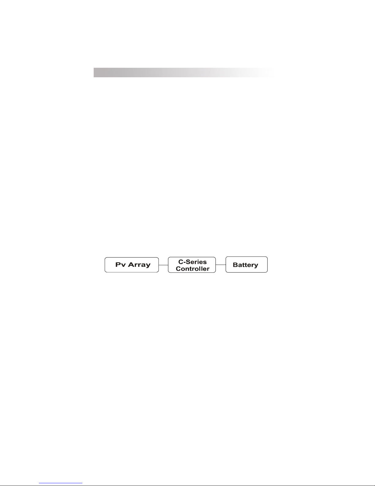
Photovoltaic Charge Control
When this mode is selected, the status LED will indicate either blinking
green or solid green. It will alternate red/green when in equalization mode.
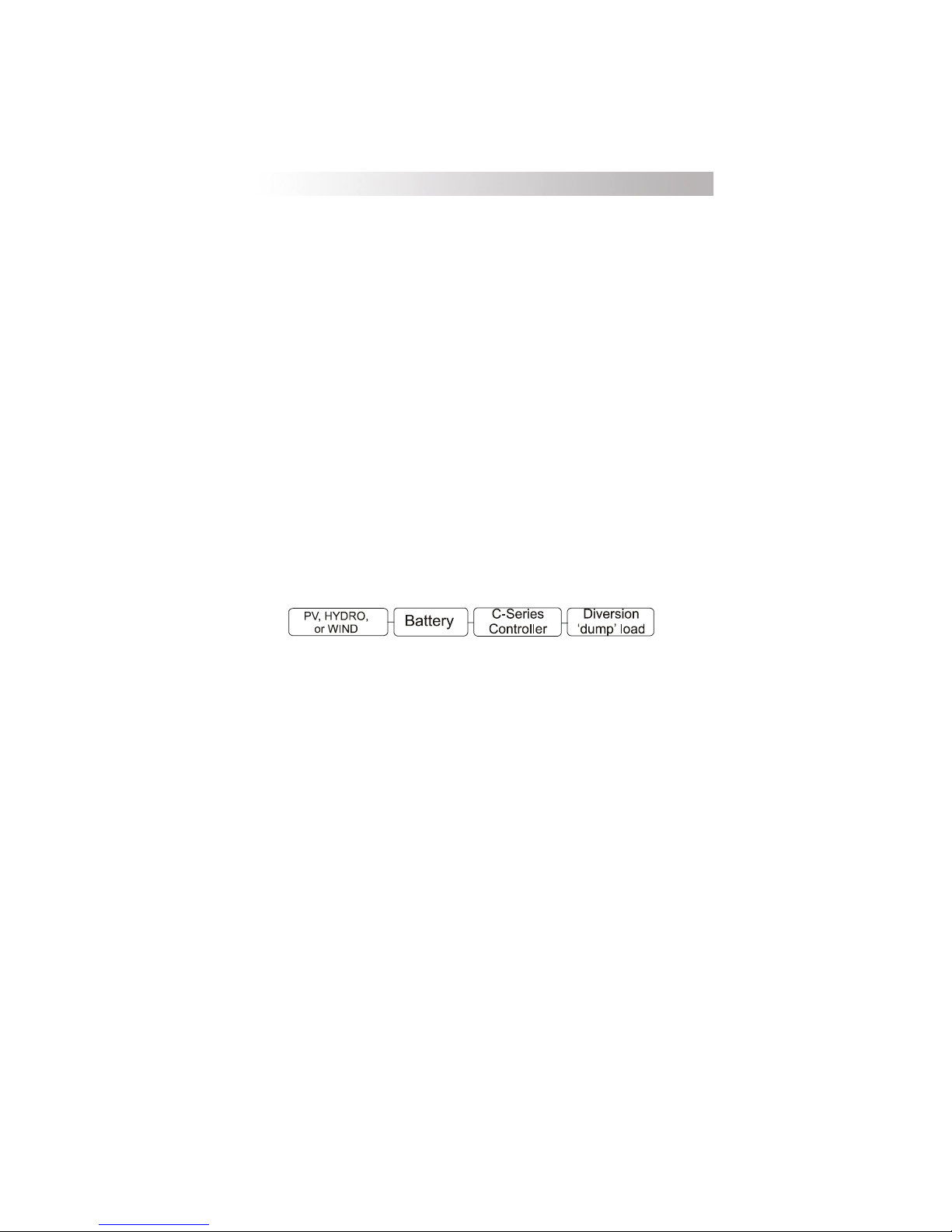
Diversion Control Mode
When this mode is selected, the status LED will indicate either blinking
green or solid green.
DC Load Control Mode
When this mode is selected, the status LED will typically indicate blinking
red or solid red as the controller turns the DC loads OFF when battery
voltage is low.
Photovoltaic Charge Control Mode
Depending on the model, the controller can regulate up to 60 amps of
continuous photovoltaic (PV) array current at 12 or 24 volts (C60), or 12, 24 or
48volts DC (C40) for charging batteries. This rating includes the NEC required
deratings. When used in this mode, ensure that the operating mode jumper is
on the charge control pins. To enable the Photovoltaic Charge Control Mode,
see Configuring the CSeries in the installation section of this manual.
If the PV arrays output increases above the rated amp level due to
reflection or edge of cloud effect, the controller will continue to operate until the
heatsink reaches a maximum safe operating temperature. This will take several
minutes to occur depending upon the ambient temperature involved. When the
heatsink reaches the maximum safe temperature, the controller will reduce the
current, cooling the transistors and the heatsink.
If the current from the PV array reaches 85 amps, the controller will turn off
to protect the circuitry. In the event of a shutdown, the controller automatically
resets itself after 10 minutes (if overcurrent condition is no longer present).
The C-Series charge controller rapidly cycles the current source on-and-off
to control the charging current and voltage of the battery. This occurs in both the
charge control mode and the diversion control mode. The amount of time the
current source is connected to the battery is varied to control the average current
flow. This is often referred to as pulse width modulation (PWM) and allows the
current to be tapered, rather than coarsely turning the current off and on as with
relay type PV array charge controllers.
2
©2000 Xantrex Technology Inc.
1.0 INTRODUCTION
Automatic PV Array Night Disconnect
At night, the PV array is automatically disconnected from the battery to
prevent reverse leakage of power. This eliminates the need for a blocking
diode between the battery and the PV array. If thin-film or amorphous solar
modules are being used, diodes may still be required to prevent damage from
partial shading conditions. Check the documentation provided with the PV
modules.
Diversion Control Mode
The C-Series can operate as a diversion control to manage battery charging
from alternative-energy sources such as wind or hydroelectric generators.
Systems utilizing solar arrays do not have a requirement for diversion loads since
a solar module can be open-circuited without damage. However, even with a
solar based system it may be desirable to use excess power to operate DC
loads. When used in this way, the C-Series controls a diversion load to redirect
the excess power generated instead of allowing it to flow into the battery. This
prevents damage to the charging source from an over-speed condition which
could occur if the charging source is suddenly disconnected from all loads as
series relay regulators do. Consult your dealer for load and regulator size
recommendations.
When the controller operates as a diversion regulator, it provides threestage regulation of battery voltage, with temperature compensation and automatic or manual equalization. See the Three-Stage Battery Charging section
for more information on this process.
Diversion mode requires a separate dump load to regulate the battery.
This load must be able to absorb more power than the charging source is able to
produce at its peak output, or the DC voltage will become unregulated. The
dump load must be available for the diversion of power at all times. Resistivetype heating elements are the best diversion loads. Special direct current
water heating elements are available. Light bulbs and motors are not recommended as diversion loads because they are unreliable.
When used in diversion mode, ensure that the operating mode jumpers are
on the charge control pins. See Configuring the CSeries in Section 3 of this
manual.
Current draw of the diversion load is very important. Problems may arise
from operating with a load that is too small or too large. A diversion load that is
too small will not be able to absorb all the excess power from the current source
once the batteries are full.
Diversion loads in excess of 85 amps are capable of absorbing more power
than the C-Series is designed to handle, resulting in an over-current shut down.
During this time, the unit will not regulate electrical flow in the system, and battery
damage may result.
A diversion load that draws about 25% more current than the charging
sources maximum output capability is usually suitable for use with the C-Series.
©2000 Xantrex Technology Inc.
3
1.0 INTRODUCTION
DC Load Control Mode
The C-Series can also operate as a load control (also called a low voltage
disconnect) to manage the discharging of the battery. A load controller
prevents damage to the battery from over-discharge during periods of poor
weather or excessive loads.
Battery
When used in load control mode, ensure that the operating mode jumpers
are on the load control pins. See Configuring the C-Series section of this
booklet.
The controller delays disconnecting the DC loads for 6 minutes after the
voltage drops below the low voltage disconnect (LVD) setting. Loads are
either automatically or manually reconnected when battery voltage exceeds the
low-voltage reconnect (LVR) setting for 6 minutes. The EQUALIZE jumper
determines manual or automatic reconnect when the C-Series is used as a load
controller.
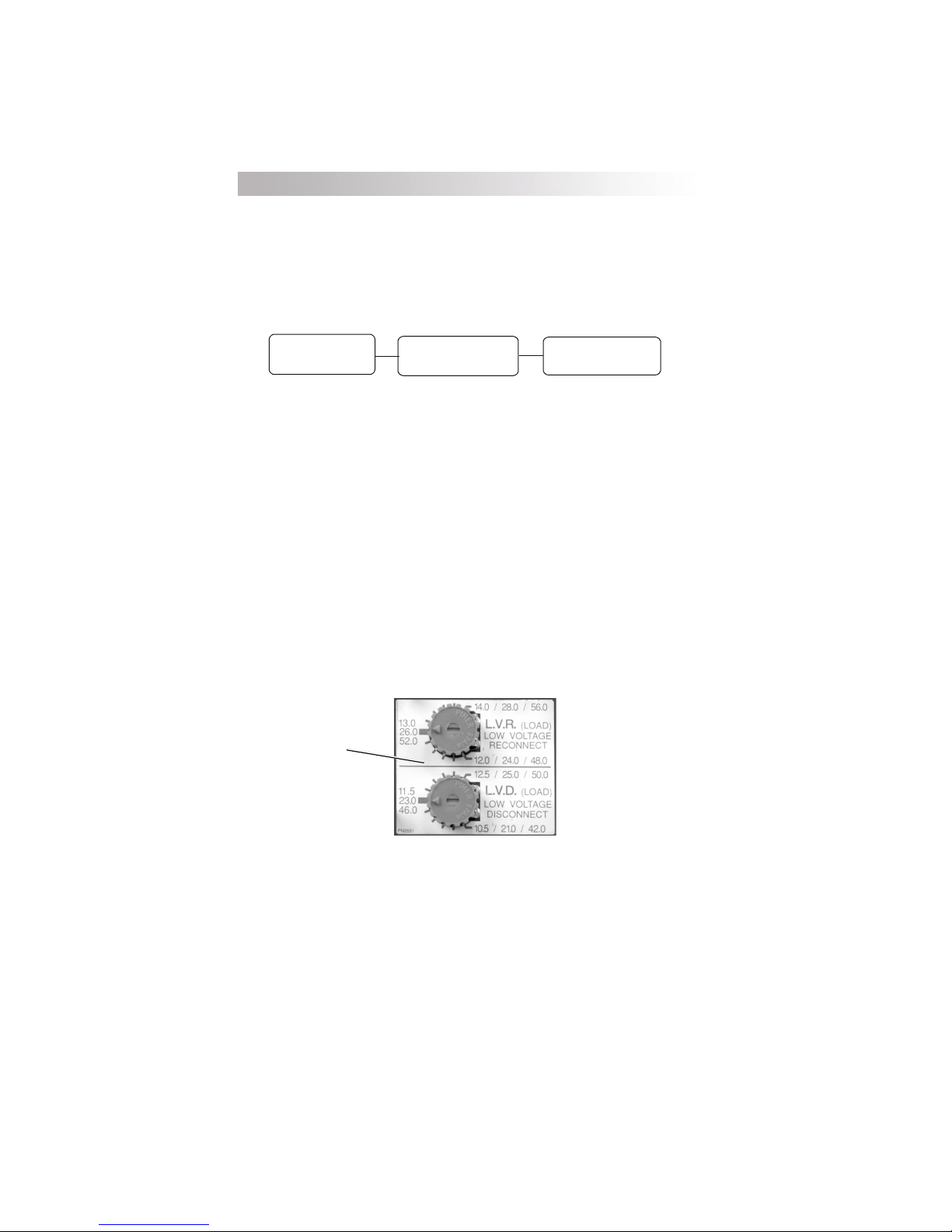
When used as a DC load controller, the settings of the LVR and LVD are
controlled by two rotary potentiometers on the circuit board. The scale on the
adjustment potentiometers differ from the scale used for other functions. A
decal with the appropriate adjustment scale is included with the C-Series and
shown below. Place this scale over the pots when using the C-Series as a
load controller. Do not temperature-compensate these settings. Do not install
the optional battery temperature compensation sensor.
Attach sticker over
potentiometers for
Load Control Settings
C-Series
Controller
DC Load
4
Sticker Displaying Load Control Voltage Settings
Figure 1
©2000 Xantrex Technology Inc.

2.0 FEATURES
Features
The C-Series features include over-temperature protection, electronic over-
current protection, and automatic battery temperature compensation.
Over-Temperature Protection
The temperature of the controllers transistors is continuously monitored.
This protects the charge controller from damage in high temperature
environments. If excessive temperatures are detected while operating in
charge or diversion control mode, the controllers transistors are rapidly turned
off and on to reduce the charge rate. This will reduce the transistor
temperature.
As a load controller, the load is disconnected before the transistors reach
an excessive temperature. Once the temperature has dropped, the loads are
reconnected. When the over-temperature protection system has caused the
controller to shutdown, the status LED will be orange and will blink fast (about
once a second). This is the same indication shown during an over-current
condition.
Electronic Over-Current Protection
During operation, the C-Series controllers continuously monitor the current
flowing through it. If the current exceeds 85 amps, the transistor switches are
opened, stopping the flow of electricity. The detection circuitry is faster than
breakers or fuses, and they will not trip or blow when a fault occurs. When
the over-current protection system is activated, the status LED will indicate
orange and will blink fast (about once a second). This is the same indication as
produced by an over temperature condition.
The C-Series controllers automatically resets the over-current protection
system every 6 minutes. If an overload or short circuit is still present, the
controller will shut off and wait another 6 minutes. This will occur continuously
until the problem is corrected.
The reset switch on the right side of the controller allows the user to
manually reconnect the PV array or DC loads after an over-current condition
occurs. Hold the reset switch for 5 seconds to return to normal operation. If
the controller is unable to restart, check the wiring and reduce the loads
connected. There may be a delay after manually pressing the reset switch
before reconnecting the PV array.
The shunt used to measure the current flow in the C-Series is located in
the positive conductor of the circuit allowing greater flexibility in system
grounding. The negative terminals are all common to one another.
©2000 Xantrex Technology Inc.
5
2.0 FEATURES
Battery Temperature Compensation
The optional plug-in external Battery Temperature Sensor (BTS)
automatically fine tunes the charging process of the C-Series. The BTS is
required by UL Standard 1741 and UL approval is based on its installation.
However, do not install the battery temperature sensor if you are using the
C-Series as a DC load controller. The BTS may be extended by using a
standard phone cable with RJ-11 plugs.
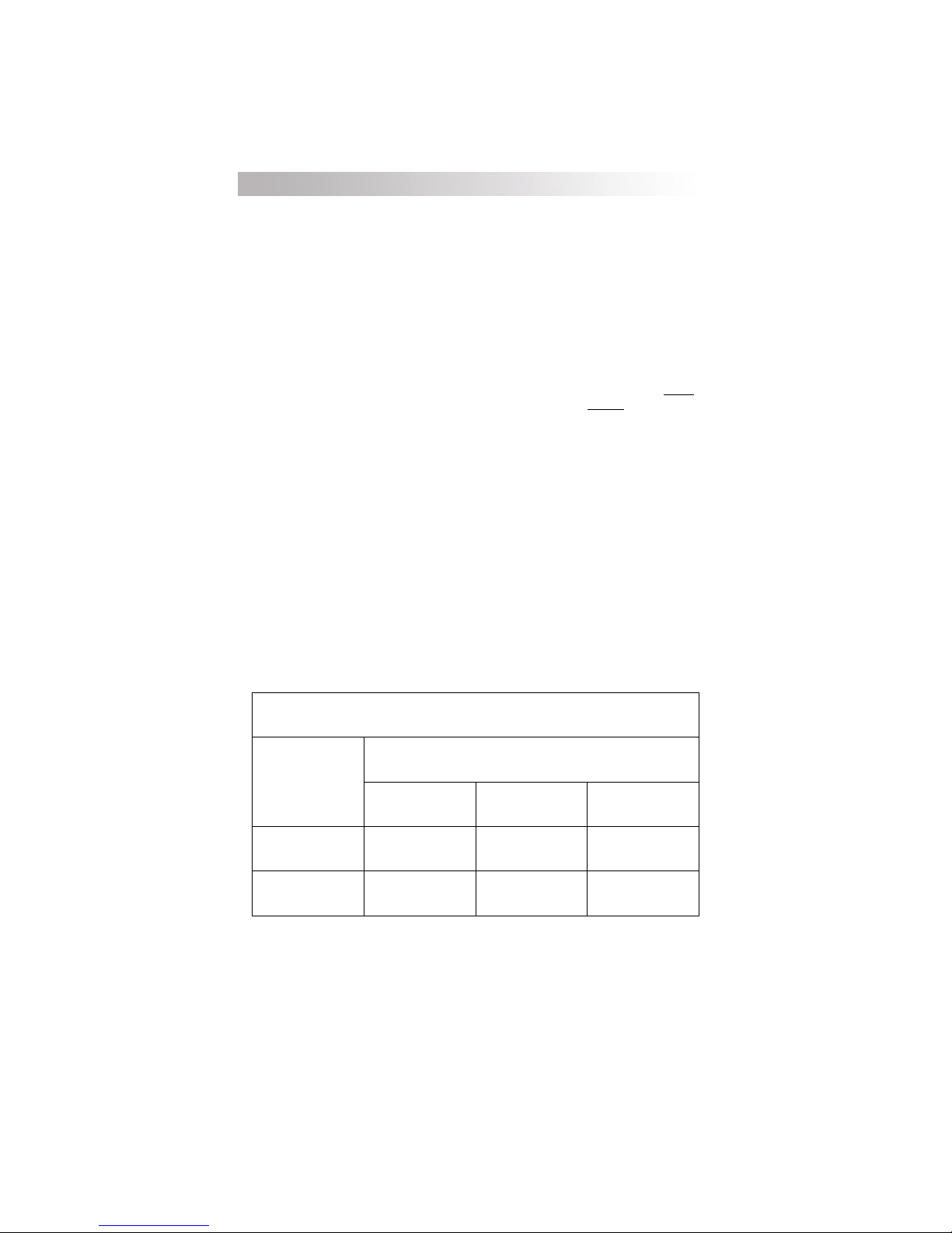
If the temperature sensor is installed, the regulation setpoints should be
adjusted for a battery at room temperature (2327 °C/7480 °F). The C-Series
adjusts the BULK and FLOAT setpoints 30 mV per degree Celsius for a
lead-acid type battery and 20 mV per degree Celsius for a
battery, as required per UL Standard 1741. For 24 and 48 volt systems, the
compensation is twice and four times the values listed respectively. See Table 1.
If the temperature sensor is NOT installed, the setpoints should be adjusted
for the temperature of the battery during operation. Seasonal adjustment of the
setpoints may be necessary to prevent battery damage and to ensure proper
charging. If the battery temperature sensor is installed, no seasonal adjustments
are required (see Temperature Compensation in this manual).
If the wiring to the sensor is damaged and the wires are shorted or cut, the
system will return to the non-temperature compensated settings.
Install the BTS on the side of the battery below the electrolyte level. It is
best to place the sensor between batteries and place the batteries in an insulated
box to reduce the influence of the ambient temperature outside the battery
enclosure. Ventilate the battery box at the highest point to prevent hydrogen
accumulation.
10-cell, NiCad type
6-cell,
TRAHCNOITASNEPMOCERUTAREPMETTNIOPTESREGRAHC
egatloVmetsyS
epyTyrettaB
CDV21CDV42CDV84
dicAdaeLC°/stlov030.0C°/stlov060.0C°/stlov021.0
daCiNC°/stlov020.0C°/stlov040.0C°/stlov080.0
Charger Setpoint Temperature Compensation
6
Table 1
©2000 Xantrex Technology Inc.
2.0 FEATURES
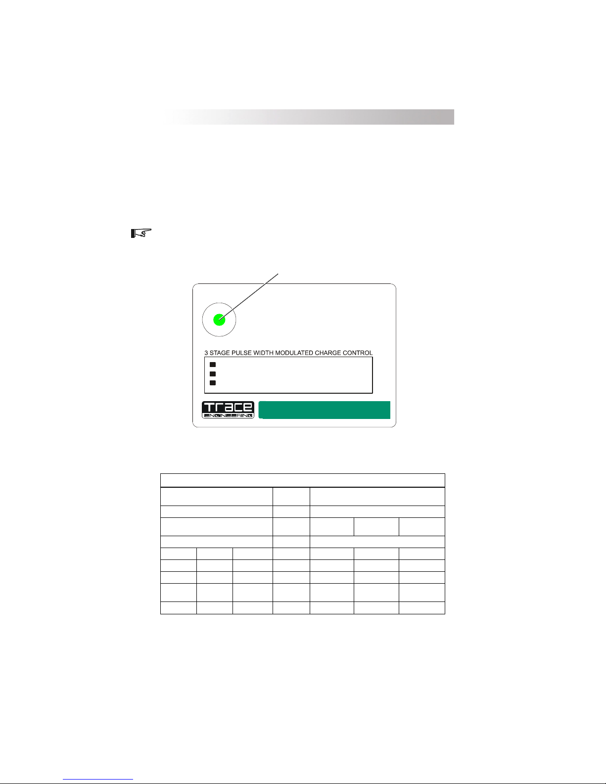
LED Status Indicator
A multi-color LED indicates the operating status of the controller. A colorcoded label is included on the cover of the controller explaining the status LEDs
operation. When the controller is in Charge Control mode, the LED will be
green. When in Load Control mode, the LED will be red. An orange LED
indicates an error or a load disconnect condition. When battery equalization is
in process, the LED alternates between red and green.
NOTE: The green and red color of the LED only indicates the particular
operating mode and the battery voltage level. It does not indicate whether the
charging source is functioning properly.
Multicolor LED Indicator
STATUS
C35
C40
C60
Green Blink Charge Control Mode
Green Solid Battery Charged
Red Blink Load Control Mode
Red Solid
Orange Blin k Slow Load Disconnected
Orange Blink Fas t
/
Green
Red
35 Amp Controller
40 Amp Controller
60 Amp Controller
Alternating - Equalization Enabled
Batte ry Dis c h arg ed
Overload/Overtemp
12/24 VDC
12/24/48 VDC
12/24 VDC
Charge / Load Controller
5916-195th STREET NE ARLINGTON WASHINGTON 98223 TELEPHONE(360)435-8826 FAX(360)435-2229
CSeries Front Panel Label
gnitteSTAOLFtayrettaB
gnitteSKLUBtayrettaB
)-(suniMgnitteSkluB )+(sulPgnitteSDVL
CDV52.0CDV05.0CDV00.1
CDV05.0CDV00.1CDV00.2
CDV57.0CDV05.1CDV00.3
57.0>
stlov21stlov42stlov84egatloVCDstlov21stlov42stlov84
05.1>
kluBwoleb
kluBwoleb
00.3>
Figure 1
)rotacidnIsutatSDELgnisU(EGATLOVYRETTAB
DEL
)edoMnoisreviD/egrahC(DELneerG
kluBwoleb
SUTATS
NOsyawlA
sknilB5
sknilB4
sknilB3
sknilB2
knilB1
51.0>
DVLevoba
CDV51.0CDV03.0CDV54.0
CDV03.0CDV06.0CDV09.0
CDV54.0CDV09.0CDV53.1
54.0>
DVLevoba
03.0>
DVLevoba
09.0>
DVLevoba
)edoMlortnoCdaoL(DELdeR
)DVL=setunim6rof(gnitteSDVLtayrettaB
54.0>
DVLevoba
53.1>
DVLevoba
©2000 Xantrex Technology Inc.
Battery Voltage LED Indications
Table 2
7

2.0 FEATURES
Charge Control or Diversion Control Mode Indications
Solid Green
The battery is being charged in the FLOAT stage. The status LED remains
ON solid unless the batteries drop below the float voltage setting for an
accumulative period of one hour. This allows the user to confirm that the
system reached the float stage during the charging process when checked at
the end of the day. Reaching the float stage frequently is a good indication of
proper system operation and will maximize battery life and performance.
Blinking Green
The controller is in the CHARGE CONTROL or DIVERSION CONTROL
mode and the battery is not fully charged. As the battery voltage approaches
the BULK setting, the status LED will blink green several times (up to five) and
then pause, indicating the battery voltage is approaching the bulk setting and
provides an indication of the battery condition. Refer to Table 2 on the previous
page to determine the battery voltage.
NOTE: A single green flash indicates the battery is below the bulk voltage
setting. It does NOT indicate the batteries are charging.
Load Control Indications
Solid Red
The controller is in the DC LOAD CONTROL mode and the battery
voltage has reached the Low Voltage Disconnect (LVD) setting. After a
6-minute delay, DC loads will be disconnected unless the user reduces the
loads to a point that the battery voltage exceeds the LVD setting.
Blinking Red
As battery voltage approaches the LVD setting, the LED will blink red
several times (up to five) and then pause providing an indication of battery
voltage. Refer to Table 2 on the previous page to determine the battery voltage.
Slow Blinking Orange
The controller is in the DC LOAD CONTROL mode and has disconnected
the loads due to reaching the LVD setting. The user can press the reset switch for
a maximum 10-minute grace period, or can wait until the voltage rises above
the Low Voltage Reconnect (LVR) setting to allow an automatic reset to occur.
8
©2000 Xantrex Technology Inc.

2.0 FEATURES
Equalization Mode Indication
Alternating Red and Green
The controller is in the EQUALIZE mode. It will automatically stop the
equalization process after accumulating two hours of operation at a voltage
above the BULK setting. The user can stop the equalization process at any time
by pressing the reset switch until the status LED stops alternating red and green.
Error Mode Indication
Fast Blinking Orange
The controller detected an over-current or an over-temperature condition
and the loads are disconnected. The controller will try to automatically restart
the loads after a 6-minute delay. If the controller will not restart, turn off all
loads and press the reset switch. If it then restarts, the loads may be too large.
A delay up to five seconds may occur before the controller attempts to restart
after pressing the reset switch.
©2000 Xantrex Technology Inc.
9

3.0 INSTALLATION
Installation
The C-Series controllers are state-of-the-art precision electronic
instruments. Installation, environment, mounting, and wiring must be
accomplished in accordance with applicable local and national electrical codes.
The instructions that follow are applicable to the typical installation. For special
applications, consult a qualified electrician or your Trace dealer. Installation
procedures will vary according to your specific application.
Mounting
The C-Series controllers are designed for indoor mounting. Care should be
taken in selecting a location and when mounting the enclosure. Avoid mounting
it in direct sunlight in order to reduce heating of the enclosure and subsequent
high operating temperatures. The enclosure should be mounted vertically on
awall.
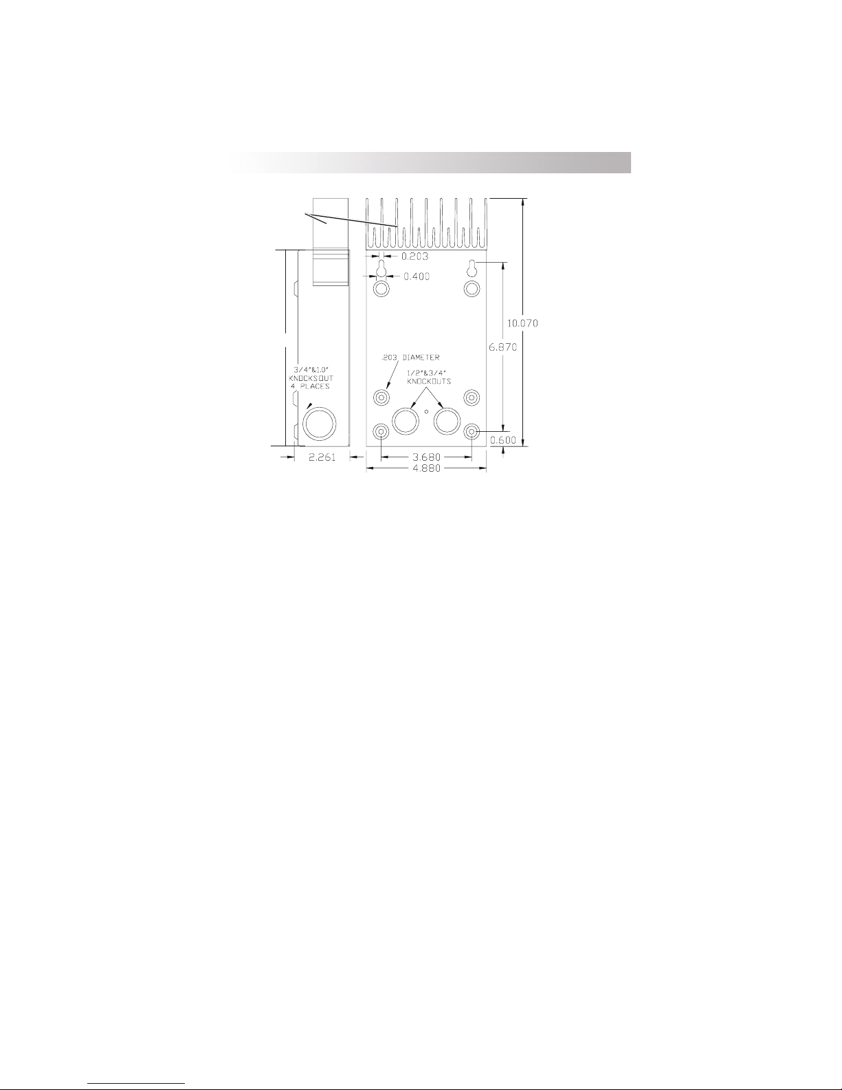
Mounting and enclosure dimensions are shown in Figure 2 (the C-35
controller does not feature an external heat sink). Remove the faceplate on the
controller and locate the upper two screw locations on the wall. The back of
the enclosure is provided with keyholes for mounting. Leave the screw heads
backed out approximately 1/4 inch (6 mm) or less. Place the controller onto the
screws and pull it down into the keyhole slots. Then insert the two lower
screws to lock the enclosure onto the wall. Provide either strain-relief clamps
or conduit to prevent damage to the circuit board and terminal block from pulling
on the wires. The cover should be replaced and retained with the screws
provided (#10-32 x 3/8" SMS).
In outdoor installations, the C-Series units must be installed in a rainproof
enclosure to eliminate exposure to rain or water-spray. The use of conformalcoated circuit boards, plated terminals, powder-coated metal components, and
stainless steel fasteners improves tolerance to hostile environments.
CAUTION: INSTALL THE C-SERIES CONTROLLER IN A DRY, PROTECTED
LOCATION AWAY FROM SOURCES OF HIGH TEMPERATURE, MOISTURE,
AND VIBRATION. EXPOSURE TO SALTWATER IS PARTICULARLY
DESTRUCTIVE. CORROSION OF THE CIRCUIT BOARD IS NOT COVERED BY
THE WARRANTY.
10
©2000 Xantrex Technology Inc.
3.0 INSTALLATION
Heatsink not included
on C-35.
8
Figure 2
CSeries Dimensions
Do not locate the C-Series controller in a sealed compartment with the
batteries. Batteries can vent hydrogen sulfide gas, which is corrosive to
electronic equipment. Batteries also generate hydrogen and oxygen gas that
can explode when exposed to a spark.
If using sealed batteries, the controller can be mounted in the same
enclosure as long as it is adequately ventilated.
©2000 Xantrex Technology Inc.
11
 Loading...