

Page 1

Trace Elliot® TE 1200
Bass Instrument Amplier
Owner’s Manual
Page 2

FCC Compliancy Statement
This device complies with Part 15 of the FCC rules. Operation is subject to the following
two conditions: (1) this device may not cause harmful interference, and (2) this device
must accept any interference received, that may cause undesired operation.
Warning: Changes or modications to the equipment not approved by Peavey Electronics
Corp. can void the user’s authority to use the equipment.
Note - This equipment has been tested and found to comply with the limits for a Class
B digital device, pursuant to Part 15 of the FCC Rules. These limits are designed to
provide reasonable protection against harmful interference in a residential installation.
This equipment generates, uses and can radiate radio frequency energy and, if not
installed and used in accordance with the instructions, may cause harmful interference
to radio communications. However, there is no guarantee that interference will not occur
in a particular installation. If this equipment does cause harmful interference to radio or
television reception, which can be determined by turning the equipment o and on, the
user is encouraged to try and correct the interference by one or more of the following
measures.
• Reorient or relocate the receiving antenna.
• Increase the separation between the equipment and receiver.
• Connect the equipment into an outlet on a circuit dierent from that to which the
receiver is connected.
• Consult the dealer or an experienced radio/TV technician for help.
CAN ICES-3(B)/NMB/3(B)
Trace Elliot • Hwy. 5022 Hwy. 493 North • Meridian, MS 39305
Tel: (601) 486-2255 • Fax: (601) 486-1156 • www.traceelliot.us
Page 3

TRACE ELLIOT® TE™1200
ENGLISH
Congratulations on your purchase of the all-new Trace Elliot TE™1200 bass amp head!
FEATURES:
•Gain control
•1200 bone-rattling watts of true RMS power!
•Built-in Lo-Band/ Hi-Band Compressors with defeat switch (footswitchable)
•Pre-shape switch for the classic Trace Elliot EQ curve (footswitchable)
•4 band equalisation
•EQ Pre/Post Compressor switch
•Mute/Tune switch (footswitchable)
•Input Gain and Output Level controls
•Pre and Post balanced XLR outputs with Ground Lift
•Headphone output
•Dimensions 12.0”W x 12.0”D x 3.62”H (305mm x 305mm x 91.9mm)
•Weight: 11.5 lbs (5.22 kg)
* Four button MIDI footswitch with 25’ cable included
* Padded gig bag included
*Optional 1.5U rackmount kit included
*Noiseless buffered effects loop with level switch (footswitchable)
*Preamp Output / Power Amp Input 1V(rms) master/slave loop
*Buffered 1/4” tuner/dry feed jack
*MIDI In and Out jacks
*USB Recording Output/Interface
*Dual Neutrik combination Speakon/phone speaker output jacks
*4 Ohm minimum load
*Worldwide AC voltage selector
Caution: Please look over this guide and read any caution or warning statements found within. Following
these warnings is crucial to your personal safety and the safety of your Trace Elliot product. Additional safety
warnings are located on the bottom of the unit.
VENTILATION: For proper ventilation, allow 12" clearance from the nearest combustible surface.
All vents should have a minimum of 2" of free air space so air can ow thru the unit freely for proper
cooling.
3
Page 4
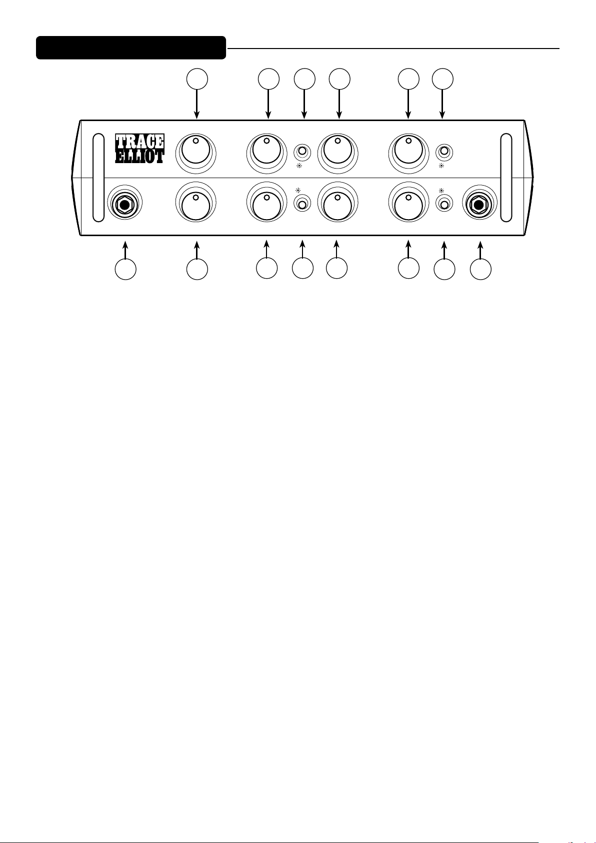
Top Panel
®
INPUT
1 3a
2 4 5 4
GAIN
LO-BAND HI-BAND
COMPRESSOR
ON ON
PRE
LO-MIDBASS HI-MID
COMPRESSOR
3c3b 6 3d
7 8
OUTPUT
TREBLE
MUTE
TE-1200
ON
PRE-SHAPEEQ PRE/POST
9 10
PHONES
(1) INPUT JACK
is is the input to the amplier preamp. e impedance is very high to allow wide frequency response and
dynamic range without loading the source.
(2) GAIN
is control sets the gain of the preamp’s input stage to compensate for various intruments and gain levels.
(3) BASS, LO-MID, HI-MID, TREBLE EQUALISATION
ese are active controls that adjust four separate equalization bands to customize the tone. e center
frequencies are as follows:
a. BASS 70 Hz
b. LOW MID 600 Hz
c. HIGH MID 2KHz
d. TREBLE 5KHz
(4) LO-BAND/ HI BAND COMPRESSORS
e audio signal is divided into two bands. Each band has a separate compressor with an adjustable threshold.
A full clockwise setting provides the most compression.
(5) COMPRESSOR ACTIVE
is switch activates the compressor functions for both low and high bands. It illuminates when active. is
function is also available on the footswitch.
(6) EQ PRE/POST COMPRESSOR
e default position of the compressor is before equalization. When the switch is pressed, the compressor is
moved to a point aer equalization, and the switch lights. e compressor will have a dierent action aer the
equalization since the tone controls will now aect it.
(7) OUTPUT
is is the master volume control for the amplier.
(8) MUTE
Mutes the preamp output. e power amp direct input on the rear panel is not muted. Mute is also available
on the footswitch.
4
Page 5

(9) PRE-SHAPE
e pre-shape switch introduces the distinctive Trace Elliot “Pre Shape 1” curve into the signal path. is
function is also available on the footswitch.
(10) HEADPHONES
A ¼” headphone output from the pre-amp is available for silent practice. When a jack is inserted, the signal to
the power amp is automatically disconnected.
5
Page 6
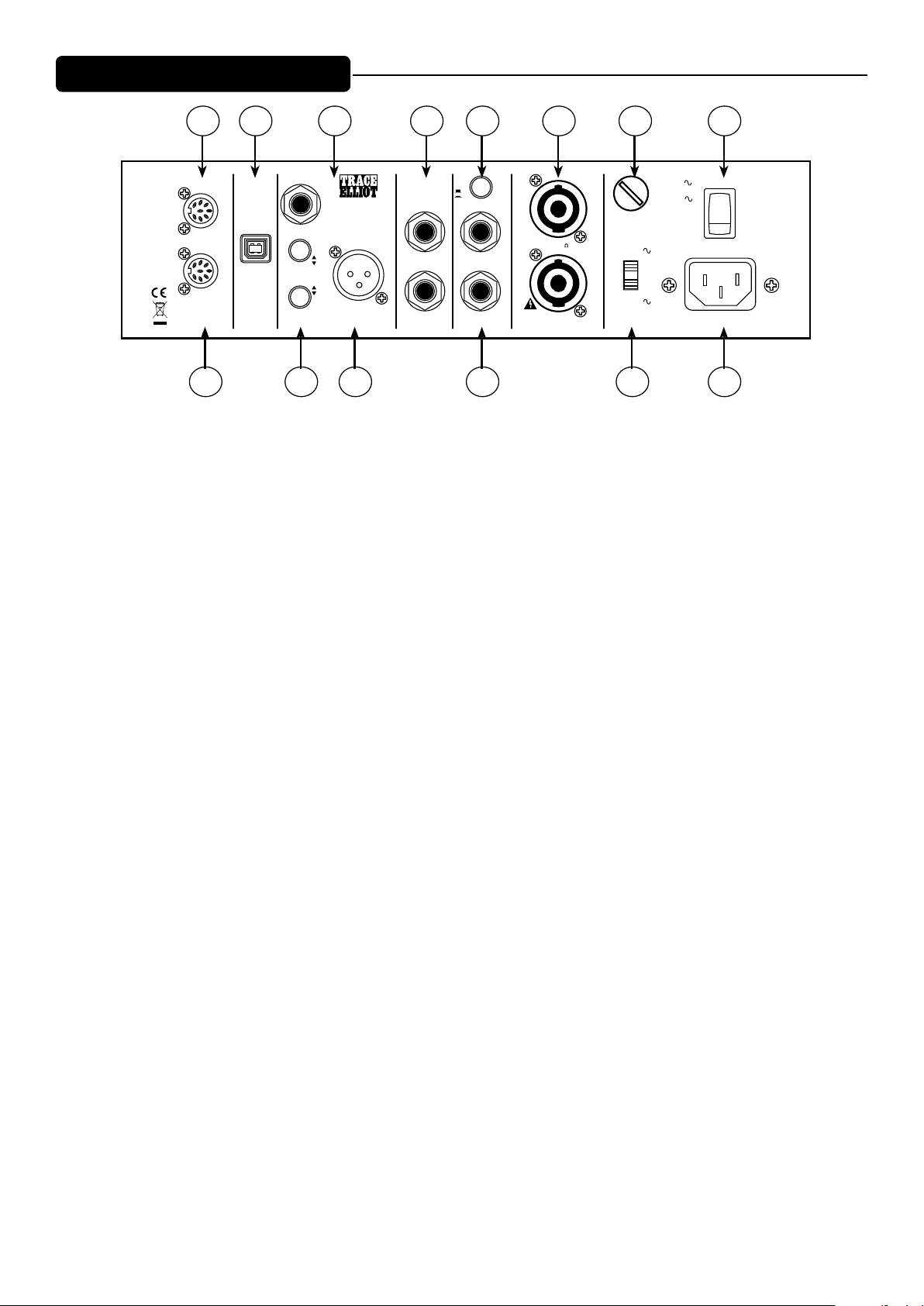
Rear Panel
TE-1200
®
GAIN
INPUT
OUTPUT
LO-MIDBASS HI-MID
TREBLE
LO-BAND HI-BAND
PHONES
MUTE
PRE-SHAPEEQ PRE/POST
COMPRESSOR
COMPRESSOR
PRE
ON ON
ON
12
OUT
FS/IN
MIDI
14 15 18 19 21 22 24
POWER
FOR 100-120V~ USE T10AH/250V FUSE
FOR 220-240V~ USE T5AH/250V FUSE
50/60 Hz 150 WATTS
Consumo de energia 150Wh
USB
REC OUT
TUNER OUT
EQ
GND LIFT
TRACE ELLIOT
TE 1200
DESIGNED IN
THE UK and U.S.A.
MADE IN CHINA
PRE
POST
LIFT
GND
DIRECT
OUT
®
®
PREAMP
OUT
POWER AMP
IN
HI
LO
EFX LEVEL
SEND
RETURN
SPEAKER
JACKS
PARALLELED
CLASS 2 WIRING
SPEAKER OUTPUTSD.I. (DIRECT INTERFACE)
4 MIN 69.3VRMS
1200W RMS 4 OHMS
FUSE
220-240V
100-120V
100-120V
T10AH/250V
220-240V
T5AH/250V
ON
252320161713
(12) MIDI OUT
When functions are toggled from the front panel or footswitch, the corresponding MIDI information is
transmitted from this jack to synchronize the function with a slave TE1200. e connection is made from this
jack to the slave’s Footswitch jack with a standard 5-pin MIDI cable. (e 8-pin Footswitch jack will accept the
5-pin cable.)
NOTE: e master unit will generate controller messages for this synchronization. It will also act as
a MIDI THRU for program change and controller messages on any channel meant for other devices,
but not ALL messages. Put the TE1200 last in line if other units in your MIDI chain need sysex and/
or other MIDI messages.
(13) Footswitch
Connect the TE1200 4-button footswitch here for parallel control of the front panel switch functions. e
8-pin cable must be used with the footswitch to provide power and bi-directional data. is jack also functions
as a standard MIDI input using a 5-pin cable. is allows you to control the TE1200 with other MIDI sources
(MIDI automation, another type of footcontroller, or a master TE1200). It will respond to the controller
messages shown below - on MIDI channel 1. Data values from 0-63 (0-0x3F in hexadecimal) will be considered
OFF, while 64-127 (0x40-0x7F in hexadecimal) will be considered ON.
01: Eects Loop (e.g. B0 01 00 for o … B0 01 7F for on)
02: Pre-Shape
03: Compressor
04: Mute
05: EQ pre-Compressor
(14) USB RECORD OUT
is is provided for connection to a computer or a digital audio workstation for recording. It is the preamp
master out signal which includes all preamp functions. ere is no input capability.
(15) TUNER OUT
A direct send from the input circuitry for a tuner. It is not processed and is fully buered. It remains active even
when the amp is muted - for silent tuning.
(16) DIRECT OUT (DI)
is is a balanced output to send to a mix console or analog recording device. It has a switch that selects
whether the output is before or aer the EQ.
6
Page 7
(17) GROUND LIFT
is disconnects the ground connection from Pin1 on the DIRECT OUTPUT connector. Usually it should be
le in the GND position, but in certain circumstances hum is produced when connecting to another device
due to grounding dierences. Liing the ground connection should eliminate the problem.
(18) PREAMP OUT/POWER AMP IN
e preamp out is the signal coming from the front panel. e power amp input is a direct connection to the
power amplier. An external processor or volume pedal can be inserted between the preamp and the power
amp if needed. Inserting a jack into the preamp output disconnects the power amp input; inserting a jack
into the power amp input also disconnects the preamp from the power amp. To use the TE1200 as a power
amplier only, apply the signal to the power amp input. is loop is aer the OUTPUT Level knob.
(19)EFX LEVEL
Some eect units are designed for lower input levels. When pressed, this switch lowers levels to prevent
distortion.
(20)EFX SEND/RETURN
ese two connectors are provided for patching an external eects processor (delay, chorus etc.) in series with
the preamp signal. e signal level is set by the EFX level switch. e eects loop can be turned on and o with
the footswitch. is loop is before the OUTPUT Level knob.
(21) SPEAKER OUTPUT CONNECTORS
is is the amplier output, with two paralleled connectors. ese connect to the speaker cabinets. e
minimum load for the amplier is 4 Ohms. is can be a single 4 Ohm cabinet, two 8 Ohm cabinets, or any
combination of cabinets whose parallel combination is greater than 4 Ohms, total. e output is a bridged
signal – both lines are driven. Do not ground either one or the unit will shut down and damage may occur.
ere can be high peak voltages on these connectors.
(22) FUSE
Use only the properly rated fuse for your line voltage.
(23) VOLTAGE SELECTOR SWITCH
Set this to your local mains voltage. An incorrect setting can damage the unit. e fuse’s rating must
match the mains voltage setting.
(24) POWER
Applies power to the unit.
(25) MAINS INPUT
is is the receptacle for an IEC line cord, which provides AC power to the unit. Connect the line cord
to this connector to provide power to the unit. Make sure the voltage setting and fuse are correct before
turning on the unit.
Never break o the ground pin on any equipment. It is provided for your safety. If the outlet used does not
have a ground pin, a suitable grounding adapter should be used, and the third wire should be grounded
properly. To prevent the risk of shock or re hazard, always make sure that the amplier and all associated
equipment is properly grounded.
7
Page 8

Specifications
Weight:
11.5 lbs (5.22 kg)
Dimensions (H x W x D):
12.0”W x 12.0”D x 3.62”H
(305mm x 305mm x 91.9mm)
Mains Voltage:
120 VAC 50/60 Hz, Fuse = T10AL/250V
220-240 VAC 50/60 Hz, Fuse = T5AL/250V
Protection:
Over temperature
Over current
Clip limiting
Short circuit
DC output
Power Output (THD+N 1%)
Minimum load = 4 ohms
Bridged output
RMS Power, 4 Ohm load 1100W
RMS Power, 8 Ohm load 835W
Nominal Input Sensitivity:
All EQ controls at 12:00, Compressors o, Shape o
Gain at 12:00 = 1.4VRMS
Gain Control Max, = 70mV RMS
Input Impedance:
>10 Meg Ohms
EQ:
LOW 70 Hz
LOW MID 600 Hz
HIGH MID 2KHz
HIGH 5KHz
Direct Output:
Balanced
Pin 1 = GND
Pin 2 = +Signal
Pin 3 = -Signal
Switchable pre/post EQ
Gnd li switch.
SPECIFICATIONS ARE SUBJECT TO CHANGE WITHOUT NOTICE
8
Page 9
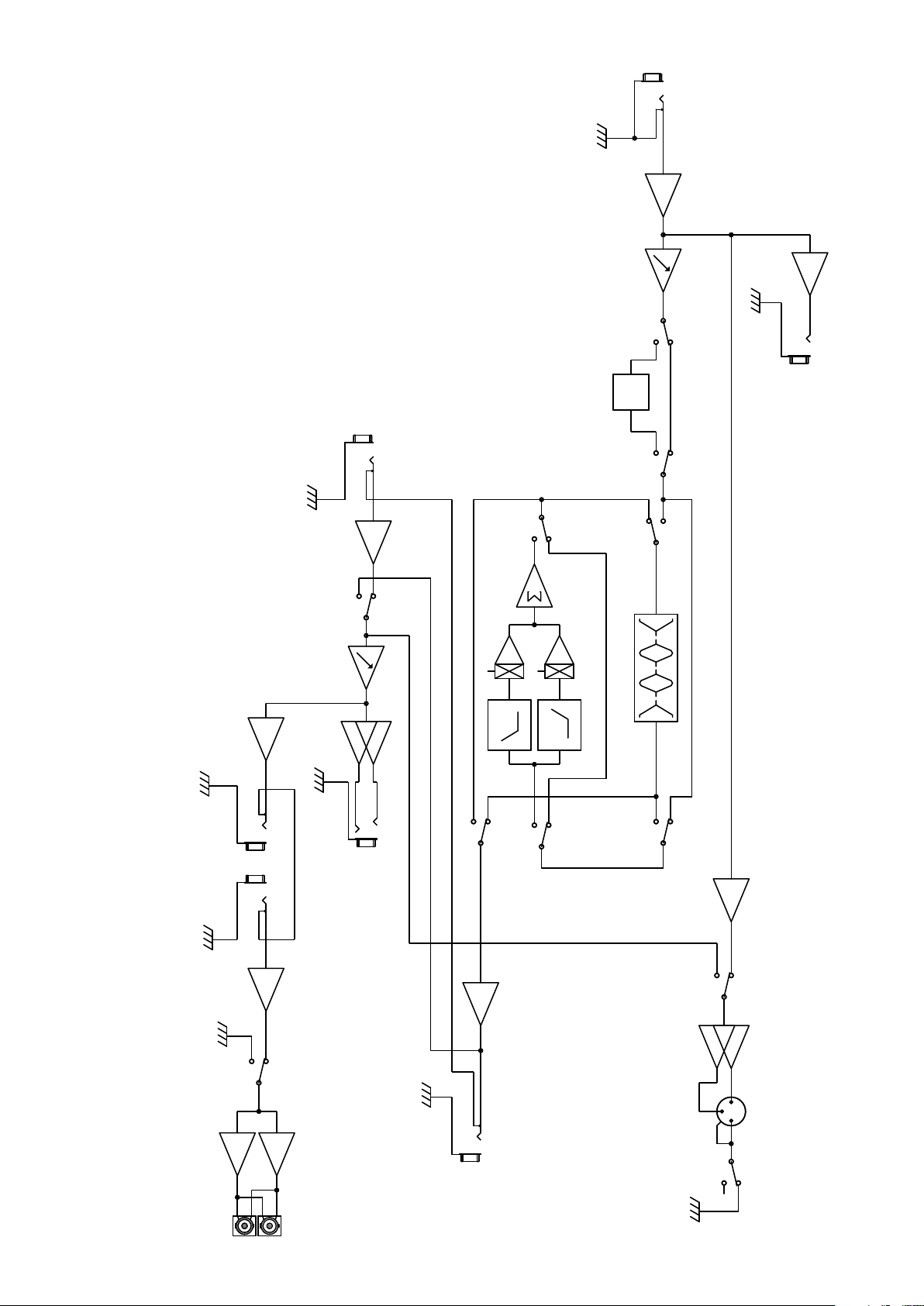
INPUT
SPEAKER
GAIN
S3 S3
PRE OUT AMP IN
VOL
FX OFF
MASTER
FX RTN
LO PASS
HI PASS
SHAPE
LO LO-MID HI-MID HI
COMPRESSORS
TUNER OUT
S1
EQ
-1
212
HP SENSE
1
HEADPHONES
FX SEND
S1
S2S2
S1
PRE/POST
2
DI OUT
3
1
4
TE-1200 Block Diagram
9
Page 10

10
Page 11

Warranty registration and information for U.S. customers available online at
www.traceelliot.com/warranty
or use the QR tag below
11
Page 12

12
Features and specications are subject to change without notice.
Trace Elliot • Hwy. 5022 Hwy. 493 North • Meridian, MS 39305
Tel: (601) 486-2255 • Fax: (601) 486-1156 • www.traceelliot.us ©2016 Printed in U.S.A. 80305734
B
 Loading...