

TRACE ELLIOT SMC RANGE, AH150-7, AH300-7, 7210H, 715 Operating Instructions Manual [en, pt, fr, nl, de +2]
...Page 1

OPERATING
INSTRUCTIONS
SMC RANGE
Page 2
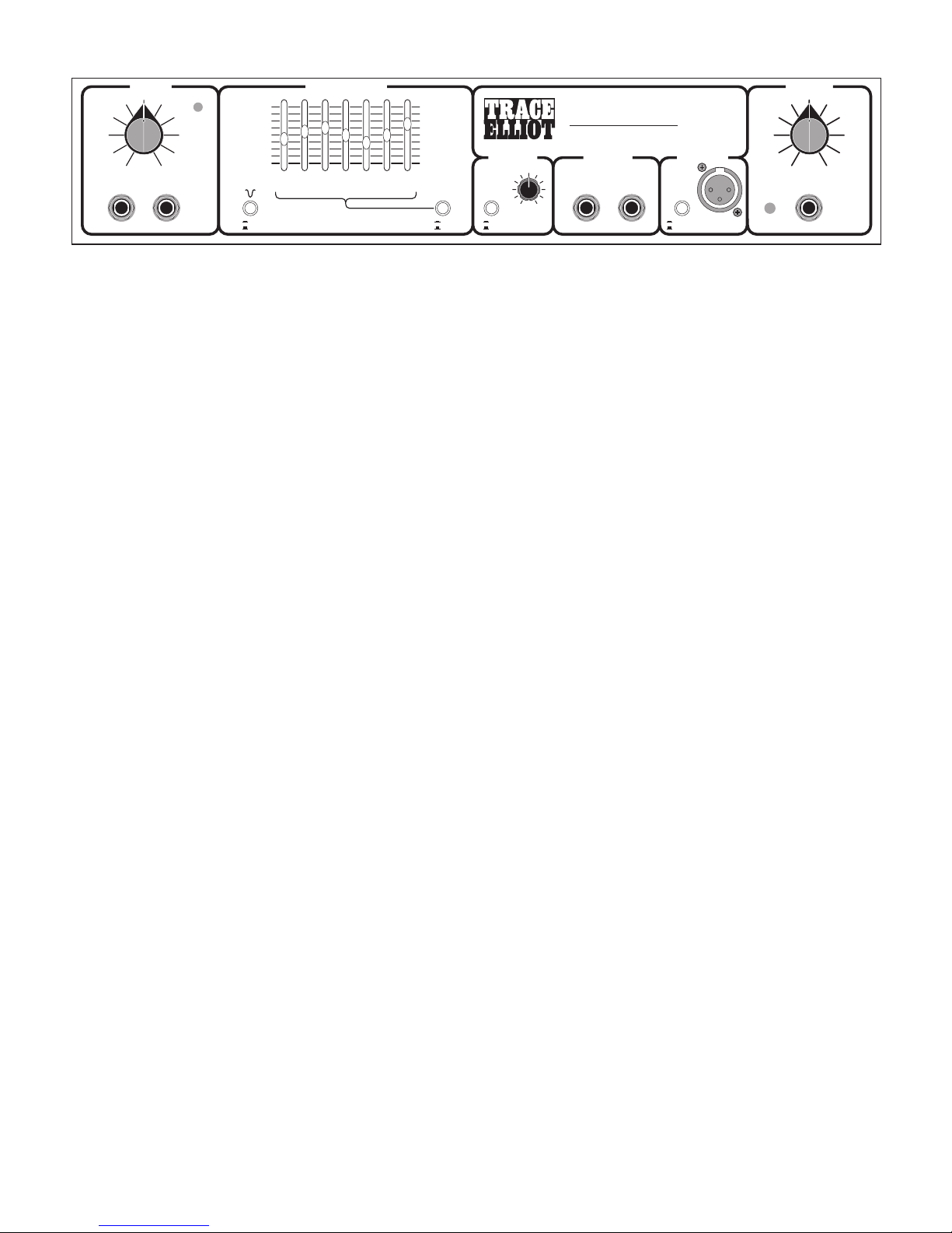
FAST TRACK GUIDE
For those familiar with TRACE ELLIOT graphic preamplifiers here is a quick run through
the facilities to get you plugged in and playing as soon as possible.
With the correct mains power connected to the mains inlet of your amplifier, and your
choice of speaker or speakers connected to the speaker output sockets, turn on the power
to the unit with the rear panel power switch.
If all is well the POWER LED on the front panel should light to indicate that the unit is
ready for use.
Plug your bass into the appropriate INPUT socket, and with the OUTPUT LEVEL control
set on ZERO adjust the INPUT GAIN control until the OVERLOAD LED flashes on with
playing peaks. It is important to set this to the correct level so that when switching in the
Dual Band COMPRESSOR you do not get a large change in volume.
Turn up the OUTPUT LEVEL control to your desired paying level and adjust your sound
using the MID PRE SHAPE, the GRAPHIC EQUALISATION, and the COMPRESSOR.
N.B. The sound is FLAT with the MID PRE SHAPE, GRAPHIC and the COMPRESSOR
switches ‘OUT’.
It may be necessary to re-adjust the INPUT GAIN control after altering the GRAPHIC or
MID PRE SHAPE.
The Dual Band COMPRESSOR is a new addition to the GP7 preamplifier and as such
deserves a short mention in this section of the instructions. This is based on the principle
used in the GP12SMX range of products where the bass signal is split into its High
frequency and Low frequency components. Each of these are then passed through
separate compressors with appropriate Attack and Decay characteristics. The two signals
are then re-combined back into a single full range signal to be passed to the rest of the
preamplifier.
The compressor is placed after the SHAPE and GRAPHIC sections to allow EQ changes
to modify the ratios of the High and Low compression.
3
0
1
2
3
4
5
6
7
8
9
10
0
1
2
3
4
5
6
7
8
9
10
-15
-10
-6
-3
0dB
+3
+6
+10
+15
-15
-10
-6
-3
0dB
+3
+6
+10
+15
GRAPHIC EQUALISATION
COMPRESSOR
OUTPUT LEVEL
LINE OUT
LEVEL
BALANCED D.I.
INPUTS
PASSIVE ACTIVE
OVERLOAD
PRE SHAPE GRAPHIC
INPUT GAIN
50Hz 100Hz 250Hz
500Hz
1KHz 2KHz 5KHz
EFFECTS LOOP
EFFECTS
SEND
EFFECTS
RETURN
GP7
7 BAND GRAPHIC
POWER
PREAMPLIFIER
Dual Band
Compression
OUT
IN
OUT
IN
POST EQ
PRE EQIN
OUT
PEAK
AH150 SMC
150 WATT BASS AMPLIFIER
Page 3

FULL OPERATING INSTRUCTIONS
Input Sockets
There are two INPUT sockets, one for PASSIVE instruments i.e. those that have no
internal preamp or battery and one for ACTIVE instruments.
The PASSIVE socket has a very high input impedance to perfectly match the output signal
from a passive instrument. This allows the full tonal range of the instrument to be
reproduced without the loss of top end that can be caused by an impedance mismatch.
This input is far more sensitive than the ACTIVE input. This is necessary because PASSIVE
basses generally have a much smaller output signal.
The ACTIVE input is suitable for the lower impedance outputs from instruments that have
their own internally powered pre amp. This input can also cope with the much higher
level of signal that some of these instruments can produce. However should you be using
an active instrument that does not have a very large signal output, then it is perfectly
acceptable to plug this into the PASSIVE input.
Input Gain
To get the best from your amplifier it is important to understand fully the correct use of
the INPUT GAIN and the OUTPUT LEVEL controls.
The optimum setting is achieved when the INPUT GAIN control is set as high as possible
without lighting the red OVERLOAD LED too often. The OUTPUT LEVEL control should
always be set as low as possible to achieve the required playing volume, i.e. the INPUT
GAIN is adjusted for the instrument and left set at the optimum level whilst the OUTPUT
LEVEL is used to make any changes to the overall amplifier volume.
To set these two controls correctly use the following procedure:-
1. First turn the OUTPUT LEVEL control to zero.
2. Plug your bass into the appropriate ACTIVE or PASSIVE socket.
3. Turn all volume controls on your bass up full.
4. Gradually turn up the INPUT GAIN control while playing your bass as hard as
you are likely to during your performance.
5. Adjust the INPUT GAIN control so that the red OVERLOAD LED lights up on
playing peaks only.
6. Now turn up the OUTPUT LEVEL control to give the desired volume.
Please note that if the GRAPHIC EQUALISATION is altered it may be necessary to readjust the INPUT GAIN control.
4
Page 4

N.B. Playing PASSIVE basses with the instruments own volume control turned back will
reduce the upper frequency response of the instrument, so try to keep this control well
advanced, using the amplifiers OUTPUT LEVEL control to provide for larger changes in
volume.
Mid Pre Shape
The MID PRE SHAPE facility is like a preset graphic equaliser built into the unit that you
can switch in or out to modify the sound of the bass.
This will add extra punch to your sound and may be used with or without the graphic
equalisation section being switched in.
The MID PRE SHAPE may be switched IN and OUT with the MID PRE SHAPE push
button switch on the front panel.
Graphic Equalisation
A GRAPHIC EQUALISER is a very flexible way of altering the sound of a bass guitar, and
if properly used will provide an extremely powerful method of tone shaping for your
instrument.
The GP7 graphic equaliser has been specially designed for the tone shaping of a bass,
and is more powerful and very different to the kind of graphic equaliser found for
instance on a Hi-Fi. Because of this there are a few rules to observe in its use.
1. Do not fully boost just one frequency band as this will tend to emphasize a small
range of notes on the bass producing a PEAKY and not very usable sound.
2. Do not boost or cut all frequency bands as this will just produce an overall change
in volume with very little tonal alteration.
3. Do not use excessive bottom (50Hz) boost unless your speakers can handle it
(very few speaker systems are capable of handling frequencies as low as this with
any degree of efficiency).
4. Do not use excessive top boost; this will tend to add a lot of hiss to the sound
(especially with ACTIVE instruments).
Useful Observations
The fundamental frequency range of a 4 string bass guitar is from 41.2Hz (bottom E
string) to around 392Hz (two octaves up on the G string) not a very wide range.
Obviously a lot of harmonics are produced when playing and these can extend up to
5Hz or more.
Other frequencies are produced by the attack portion of the note when the string is first
struck. This attack can be emphasized by boosting the top end.
5
Page 5

However because of the fairly small range of frequencies produced by a bass, by top end
we mean between 2 and 5 kHz. You will find by boosting at 5kHz the ATTACK will be
emphasized whereas by boosting at 1kHz and 2kHz you will bring out the harmonics in
the note.
Use the 50Hz slider sparingly unless you have a stack of speakers available, and the
power amps to drive them. Rolling off the bottom end by using this slider to give a
degree of cut will allow you to play at a far greater volume level without the speakers
complaining. You will find that boosting at 100Hz will give a greater perceived increase
in bottom end than boosting at 50Hz.
Using The Graphic
Try to keep the slider settings balanced around the 0dB (centre) line on the graphic.
Set the sliders in a smooth, gentle curve, as setting adjacent sliders at opposite extremes
will give sharp peaks and troughs in the sound.
Switch the graphic IN and experiment with the available sounds but remember TOP end
means 1kHz to 5kHz, BOTTOM end means 50Hz and 100Hz and MID range means
250Hz and 500Hz.
N.B. Don’t forget to re-adjust the INPUT GAIN setting once you have altered the graphic.
This is necessary because altering the graphic will change the overall gain. The level
indicating circuit monitors the signal to ensure that clipping or distortion is not occurring
at any stage. Consequently changing the gain will change the reading on the LED and
you will have to re-adjust the INPUT GAIN control to compensate.
The GRAPHIC may be switched IN and OUT with the GRAPHIC push button switch on
the front panel.
Compression
TRACE ELLIOT have always avoided including compression in any of their previous
amplifiers as the integrity of the signal has always been paramount in all designs. The
reason for this is simply that any kind of FULL RANGE compression used in bass is
always an unacceptable compromise. It cannot act fast enough to catch attack transients,
and if it does then it distorts the low frequency signals. If you have used any full range
compression then you will know what we mean.
That was before the TRACE ELLIOT SMX series of amplifiers where we developed a
compressor in which the bass signal is split into its HIGH and LOW frequency
components, and each passes through its own compressor, one optimized for LOW
frequencies and one optimized for HIGH frequencies.
The signals from these two compressors are then recombined into a single bass signal
providing FULL RANGE compression without the drawbacks of a single compressor.
6
Page 6

This principle has been used in the SMC series of amplifiers i.e. two compressors are
used, however the controls for these two compressors have now been simplified to
one rotary control that adjusts the compression level for both the HIGH and LOW
frequency compressors simultaneously.
Separate attack and release characteristics are used for the HIGH and LOW
compression, fast for the HIGH compression and medium to slow for the LOW. Fast
is needed on the HIGH compression in order to catch the initial high frequency
transients on striking the string, if however this speed of attack is used for the LOW
compression it produces distortion on low bass notes.
If the slower attack is used on the high frequencies then any initial transient will get
through unchecked and subsequent transients will disappear as the low bass
compression would not have had time to recover, i.e. the release is too slow for the
high frequencies.
Use Of Compression
Adding a small amount of compression gives a fat bottom end to the sound and
allows a greater volume of amplification to be used without the playing peaks
distorting the sound.
You will also find that this will add definition to your playing bringing out notes
within a run more clearly as it evens out the dynamics of your playing.
A large amount of compression can be used as an effect but it will tend to reduce the
dynamics in your playing to such an extent that the volume of the note will almost
be the same no matter how hard or soft you hit the string.
Compression also adds sustain to notes making them longer before they die away.
The Compressor may be switched IN or OUT with the compression push button
switch on the front panel.
Effects Send And Return
The SMC preamp is provided with a serial effects loop and the sockets for this are
located on the front panel.
The EFFECTS SEND socket is for linking the preamp sound into your effects unit and
the EFFECTS RETURN socket for returning th signal back to the preamp.
As this is a SERIAL effects loop then you will need to adjust the balance of direct to
effects sound within your your effects unit (i.e. dry/wet mix).
The signal path through the preamp is only broken when a jack plug is inserted into
the EFFECTS RETURN socket, so the EFFECTS SEND signal may be used as a pre
master volume LINE OUT socket or connected to a tuner. This will allow silent
tuning by turning the OUTPUT LEVEL to zero, tuning up and returning the OUTPUT
LEVEL control back to its original setting.
The EFFECTS SEND socket is located after all EQ and after the compressors
7
Page 7

Balanced DI
A balanced DI output is provided on the SMC preamp for direct connection to a
balanced ‘Mic’ input on a mixing desk. This may be used for either Direct Injection of the
bass into a PA system or for recording purposes.
The balanced DI is provided on a standard Male XLR socket located on the front panel.
The signal from the preamp fed to this output socket is selectable between PRE EQ and
POST EQ.
PRE EQ takes its signal from before the graphic equalizer but after the mid pre shape.
POST EQ takes its signal from after all equalisation, after the compressors, and after the
effects loop, but before the output level control.
The level of the DI output is fixed at a suitable level to suit the low impedance ‘Mic’
input on a mixing desk. This level is dependant on the setting of the INPUT GAIN control
and it is important to have this set correctly (see INPUT GAIN section).
Power LED
This LED indicates when the unit is connected to the mains supply and switched on.
Line Output
The LINE OUTPUT jack socket can be used for connection to further power amplifiers to
allow the building of a higher powered bass system. The signal on this socket is taken
from after the OUTPUT LEVEL control so that a single control will increase or decrease
the volume of the entire system simultaneously.
The LINE OUT socket is configured such that it may also be used as a LINE INPUT. This
may be used to interconnect or LINK two preamps together so that both preamps will
drive both sets of power amplifiers and speakers with the volume of each preamp still
being set by its own OUTPUT LEVEL control. i.e. two combos could be linked in this
way with each preamp driving both sets of speakers.
Output Level
The OUTPUT LEVEL control is used to set the overall volume of the amplifier. As stated
earlier set the INPUT GAIN control as high as possible so that the overload LED lights on
playing peaks and set the OUTPUT LEVEL control as low as possible to achieve the
required playing level.
In this way you will have the best possible sound with the minimum of background
noise, the compression will operate at its optimum and you will also have the correct
output level from the DI socket.
8
Page 8
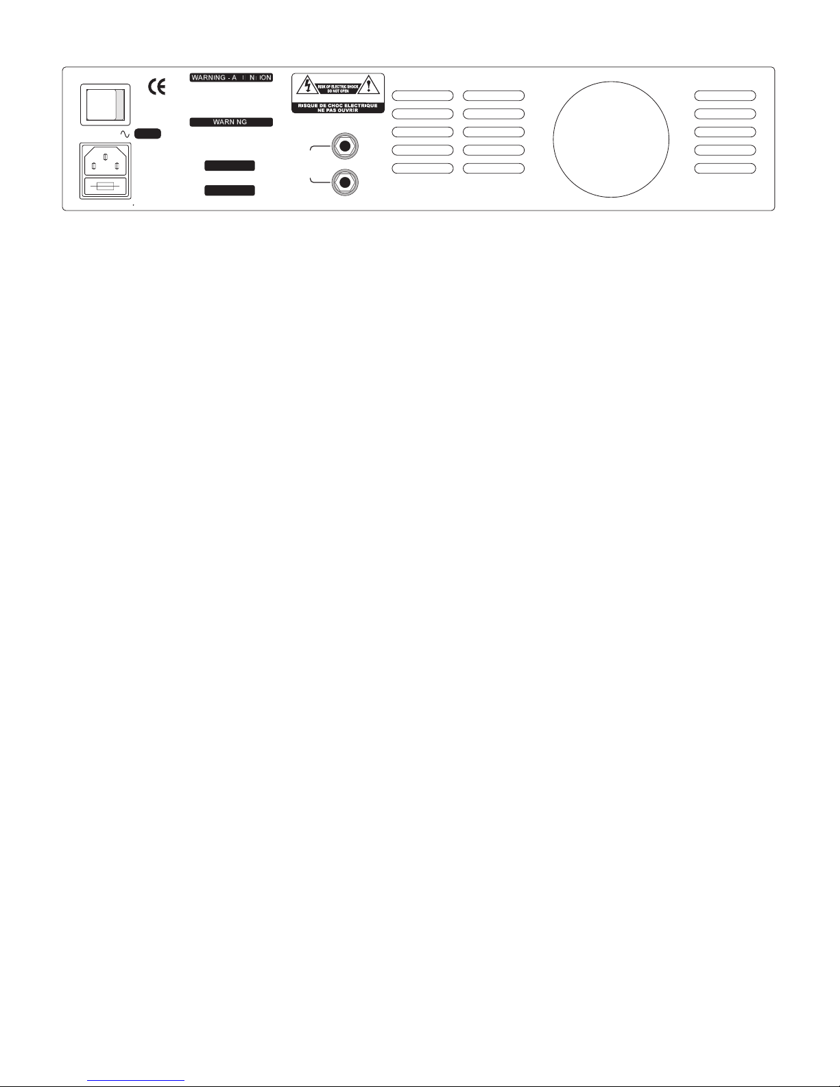
BACK PANEL FACILITIES
Mains Inlet Socket
For connection to your countries mains supply. Ensure that the amplifier has the correct
voltage marked on the back for your country prior to connecting the mains power cable
to the supply.
For your own safety be sure that the power supply socket that you are plugging into is
adequately earthed.
The MAINS INLET also contains the fuse carrier beneath it that holds the 20mm supply
fuse for the unit. In the event of failure of this fuse always replace it with the same rating
and type as marked on the rear panel (see Warnings and Safety Instructions section).
Power Switch
This is used for turning the power to the unit ON or OFF. The POWER LED on the front
panel will light to indicate when the power to the unit is turned ON.
Always make a habit of reducing the OUTPUT LEVEL control to zero before turning the
unit on or off. This is just good sense really as any bass connected to the input of the
amplifier could cause hum pick up or start feeding back if left unattended when the unit
is switched on.
Ventilation Slots
Ventilation slots are provided on the back of the unit to allow the free flow of air over the
heatsink to cool the output stage.
Do not block or impede the airflow through these
slots or the amplifier will fail in use when the internal thermal trip cuts off your signal
to the speakers because of over temperature.
SPEAKER
OUTPUTS
MIN LOAD
= 4 OHMS
SERIAL No:-
THIS APPARATUS MUST BE EARTHED.
FOR CONTINUED PROTECTION
AGAINST RISK OF FIRE REPLACE ONLY
WITH SAME TYPE AND RATING OF FUSE.
UTILISER UN FUSIBLE DE RECHANGE DE
MEME TYPE ET CALIBRE.
TO REDUCE THE RISK OF FIRE OR
ELECTRICAL SHOCK DO NOT EXPOSE
THIS EQUIPMENT TO RAIN OR MOISTURE.
50/60Hz
V A.C.
POWER
OFF ON
MODEL No:-
MANUFACTURED IN ENGLAND BY:- TRACE ELLIOT LTD
115 V - T6.3 A
230 V - T3.15 A
MAINS INPUT 260V A 115V @ 2.2 A
CAUTION
ATTENTION
o
I
9
Page 9

SMC SERIES PREAMP SPECIFICATIONS
Inputs Passive Bass Input Impedance 2 MΩ
Signal Range 50mV to 10V peak to peak
Active Bass Input Impedance 100kΩ
Signal Range 100mV to 20V peak to peak
Effects Return Impedance 22kΩ
Signal Level -10dBv
Outputs Effects Send Impedance 22kΩ
Nominal Level -10dBv
Line Out Impedance 1kΩ
Nominal Level 0dBv
DI Output Impedance 600 Ω Balanced
Nominal Level 600mV peak to peak
EQ Graphic +/- 15dB at 7 centre frequencies
Mid Pre Shape +6dB @ 50Hz & 2kHz, -6dB @ 400Hz
Compression Dual Band Compression, Crossover point 350Hz
Maximum compression ratio 20:1
Frequency Response -3dB @ 20Hz & 22kHz
Signal/Noise Ratio Better than 80dB (EQ flat, mid & comp out)
Distortion Less than 0.05% THD
10
Page 10

SAFETY INSTRUCTIONS
Warning
For continued protection against the risk of fire, replace fuses only with fuses of the same type
and rating.
To reduce the risk of fire or electric shock, do not expose this equipment to rain or moisture.
In the event of a suspected malfunction, always refer this equipment to a qualified service
engineer.
This apparatus must be earthed. The wires in this mains are coloured in accordance with the
following code:-
Green& Yellow
- Earth
Blue
- Neutral
Brown
- Live
As the colours of the wires in the mains lead of this appliance may not correspond with the
coloured markings identifying the terminals in your plug, proceed as follows:The wire which is coloured Green & Yellow must be connected to the terminal in the plug which
is marked with the letter E or by the earth symbol or coloured green or Green and Yellow.
The wire which is coloured Blue must be connected to the terminal which is marked with the
letter N or coloured Black.
The wire which is coloured Brown must be connected to the terminal which is marked with the
letter L or coloured Red.
If A 13 amp (BS1363) plug is used a 13 amp fuse must be fitted, or if any other type of plug is
used a 15 amp fuse must be fitted either in the plug or adaptor or at the distribution board.
EMC Warning
It is inherent in the design of a loudspeaker and in the design of guitar pickups that they should
emit or be affected by electro magnetic fields. Trace Elliot loudspeaker enclosures should not be
used less than 2 metres away from equipment which is likely to be affected by electro magnetic
interference.
Likewise, guitars fitted with electro magnetic pickups should not be used less than 2 metres away
from any source of electro magnetic emissions such as loudspeakers.
Emissions from loudspeakers are dependent on the frequency characteristic of the drive unit.
Levels were measured direct from the drivers of 30 dBuV.
These levels are reduced to a safe level at a distance of 1.27 metres from the drivers.
CONSIGNES DE SECURITE
Attention
Pour une protection continue contre les incendies, ne remplacez les fusibles que par des fusibles
du mÍme type et du mÍme courant nominal.
Pour réduire le risque díincendie ou de décharge électrique, níexposez jamais cet équipement à la
pluie ou à líhumidité.
Si vous soupÁonnez une défaiilance, faites toujours appel à un ingénieur qualifié.
Cet appareil doit Ítre mis à la masse. Les fils de cette conduite díamenée de secteur sont colorés
selon le code suivant:
Vert & Jaune
- Masse
Bleu
- Neutre
Marron
- Tension
Etant donné que les couleurs des fils de la conduite díamenée de secteur de cet appareil risquent
parfois de ne pas correspondre aux couleurs identifiant les bornes de votre fiche, procédez
comme suit:
Le fil Vert & Jaune doit Ítre relié à la borne de la fiche marquée de la lettre E, du symbole de terre
ou colorée en Vert et Jaune.
Le fil Bleu doit Ítre relié à la borne marquée de la lettre N ou colorée en Noir.
Le fil Marron doit Ítre relié à la borne marquée de la lettre L ou colorée en Rouge.
Si vous utilisez une fiche 13 amp (BS1363) vous devez utiliser un fusible 13 amp. Si vous utilisez
un autre type de prise, installez un fusible 15 amp dans la prise, dans líadaptateur ou dans le
tableau de distribution.
Compatibilité électromagnétique - avertissement
La conception d’un haut-parleur et des pickups de guitare est telle qu’ils sont affectés par des
champs électromagnétiques ou en émettent les enceintes de haut-parleur Trace Elllot ne devraient
pas étre utilisées à moins de 2 mètres de l’équipement susceptible d’être affecté par les parasites
électromagnétiques.
Les émissions en provenance de haut-parleurs dépendent de la caractéristique fréquentielle de
l’émetteur piloté.
De même, les guitares équipées de pickups électromagnétiques ne devraient pas être utilisées à
moins de 2 mètres de toute source d’émissions électromagnétiques telles que des haut-parleurs.
Les niveaux ont été mesurés directement à partir des drivers de 30 dBuV.
Ces niveaux sont réduites à un niveau sûr à une distance de 1,27 mètre des drivers.
SICHERHEITS-ANWEISUNGEN
Warnung
Zum fortdauernden Schutz gegen Feuerrisiken die Sicherungen nur durch Sicherungen desselben
Typs und derselben Nennleistung austauschen.
Um das Risiko von Feuer oder Elektroschock zu reduzieren, dieses Gerät keinem Regen und
keiner Feuchtigkeit aussetzen.
Im Fall eines vermuteten Defekts muß dieses Gerät einem qualifizierten Service-Techniker
übergeben werden.
Dieses Gerät muß geerdet werden. Die Drähte im Stromkabel wurden dem folgende Code nach
koloriert:
Grün & Gelb
- Erde
Blau
- Neutral
Braun
- Stromführend
Da die Farben der Drähte dieses Geräts nicht notwendigerweise den Farbmarkierungen der Pole
in Ihrem Stecker entsprechen, sollten Sie wie folgt vorgehen:
Der grün/gelbe Draht muß an den Pol im Stecker angeschlossen werden, der mit dem
Buchstaben E oder dem Erde-Symbol oder der Farbe Grün oder Grün/Gelb markiert ist.
Der blaue Draht muß an den Pol angeschlossen werden, der mit dem Buchstaben N oder
schwarz markiert ist.
Der braune Draht muß an den Pol angeschlossen werden, der mit dem Buchstaben L oder rot
markiert ist.
Falls ein 13 amp (BS1363) Stecker benutzt wird, muß eine 13 amp Sicherung eingesetzt werden;
und falls ein Stecker anderer Art benutzt wird, muß eine 15 amp Sicherung entweder im Stecker
selbst oder an der Verteilertafel eingesetzt werden.
EMC Warnung
Es liegt im Design eines Lautsprechers und im Design von Gitarrenaufnehmern, daß sie
elektromagnetische Felder abgeben oder von solchen beeinflußt werden. Trace Elliot
Lautsprechergehäuse sollten daher nicht in unter 2 Metern Entfernung von Geräten benutzt
werden, die durch elektromagnetische Störungen beeinflußt werden könnten.
Auch sollten Gitarren, die mit elektromagnetischen Aufnehmern ausgestattet sind, nicht in unter
2 Metern Entfernung von Quellen elektromagnetischer Emissionen, wie z.B. Lautsprechern,
benutzt werden.
Die Lautsprecheremissionen sind von der Frequenzcharakteristik der Treiber-Einheit abhängig.
Die Werte wurden direkt von den Treibern von 30 dBuV gemessen.
Diese Werte reduzieren sich in einer Entfernung von 1,27 Metern von den Treibern auf ein
sicheres Maß.
INSTRUCCIONES DE SEGURIDAD
Advertencia
Para una protección continua contra el riesgo de incendio, reemplace siempre los fusibles con
otros del mismo tipo y valor.
Para reducir el riesgo de incendio o descarga eléctrica, no exponga este equipo a la lluvia o a la
humedad.
En caso de que sospeche que exista un desperfecto, refiera siempre este equipo a un ingeniero
de servicio calificado.
Este aparato debe tener conexión a tierra. Los cables de esta toma se colorean según el código
siguiente:-
Verde & Amarillo
- Tierra
Azul
- Neutro
Marrón
- Vivo
Como los colores de los cables de la toma principal de este aparato pueden no corresponder con
los colores marcados que identifican los terminales en su enchufe, proceda como se indica a
continuación:El cable verde y amarillo debe conectarse al terminal del enchufe marcado con la letra E, por el
símbolo de tierra, o pintado de verde o verde y amarillo.
El cable azul debe conectarse al terminal marcado con la letra N o pintado de negro.
El cable pintado de marrón debe conectarse al terminal marcado con la letra L o pintado de Rojo.
Si se usa un enchufe de 13 amperios (BS 1363), se deberá poner un fusible de 13 amperios, o un
fusible de 15 amperios si se usa cualquier otro tipo de enchufe, ya sea en el enchufe, en el
adaptador o en la placa de distribución.
Advertencia EMC (de compatibilidad electromagnética)
Es inherente en el diseño de un altavoz y en el de las pastillas de guitarra que emitan o se vean
afectados por campos electro magnéticos. Los recintos de los altavoces Trace Elliot no deberán
usarse a menos de 2 metros de distancia de cualquier equipo que pueda ser afectado por
interferencias electromagnéticas.
Asimismo, las guitarras que tienen pastillas electromagnéticas no deberán usarse a menos de 2
metros de distancia de ninguna fuente de emisiones electromagnéticas tales como los altavoces.
Las emisiones de los altavoces dependen de la característica de frecuencia del equipo de
accionamiento.
Los niveles se midieron directamente desde unidades de accionamiento de 30 dBuV.
Estos niveles se reducen a un nivel seguro a una distancia de 1,27 metros desde las unidades de
accionamiento.
11
Page 11

SIKKERHETSANVISNINGER
Advarsel!
For å hindre fare for brann må du alltid skifte en røket sikring ut med en av samme type og
størrelse.
For å redusere faren for brann eller støt må høyttaleren ikke utsettes for regn eller fuktighet.
Hvis du har den minste mistanke om feil må høyttaleren repareres av en kvalifisert tekniker.
Høyttaleren må jordes. Ledningene har følgende fargekode:
Grønn og gul - jord Blå - nøytral Brun - strømførende.
Hvis fargekoden ikke stemmer overens med støpselets fargekoder, går du frem slik:
Den grønne og gule ledningen må kobles til støpselets terminal merket E eller med
jord–symbolet, eller farget grønn og gul.Den blå ledningen må kobles til terminalen merket N eller
farget sort.Den brune ledningen må kobles til terminalen merket L eller farget rød.Høyttaleren må
kobles til en 16 ampere krets.
Advarsel – elektromagnetisk forenlighet
Alle høyttalere og pick–up'er til gitarer gir nødvendigvis fra seg eller påvirkes av
elektromagnetiske felter. Trace Elliot–høyttalerkabinetter må ikke brukes mindre enn 2 m fra utstyr
som trolig kan påvirkes av elektromagnetisk støy.
Gitarer med elektromagnetisk pick–up må likeledes ikke brukes mindre enn 2 m fra en
elektromagnetisk kilde, som f.eks. høyttalere.Utstrålingen fra en høyttaler avhenger av
frekvenskarakteristikken til driver–enheten.Nivåene ble målt direkte fra utganger på 30 dBuV.
Disse nivåene faller til et trygt nivå i en avstand av 1,27 m fra utgangene.
SÄKERHETSFÖRESKRIFTER
Varning
För oavbrutet skydd mot brandrisk, byta ut säkringar endast med samma typ av säkring och
styrka.
För att minska risken för brand eller elektriska stötar, utsätt inte utrustningen för regn eller fukt.
I händelse av en oförutsedd felaktig funktion så vänd er alltid en behörig serviceingenjör.
Denna apparat måste vara jordad. Ledningarna i stickproppen har färger enligt följande kod:
Grön och gul - Jordning Blå - Neutral Brun - Spänningsförande
Eftersom färgerna i apparatens sladd kanske inte överensstämmer med färgmarkeringarna som
identifierar terminalerna i stickproppen, gör enligt följande:
Den ledning som är grön och gul måste anslutas till den terminal i stickproppen som markeras
med bokstaven E eller genom jordsymbolen eller grön och gul färg.
Den ledning som är blå måste anslutas till den terminal som är markerad med bokstaven N eller
svart färg.
Den ledning som är brun måste anslutas till den terminal som är markerad med bokstaven L eller
röd färg.
Om en A 13 amp (BS1363) stickpropp används måste en 13 amp säkring användas eller om
någon annan sorts stickpropp används måste en 15 amp säkring användas i stickproppen eller i
en förgreningspropp eller i fördelningstavla.
Emissionsströmsvarning
Det är ingår i konstruktionen på högtalare och gitarrers pick-uper att de skall påverkas av
elektromagnetiska fält. Trace Elliots högtalarlådor skall inte användas närmare än 2 meter från
utrustning som kan påverkas av elektromagnetiska störningar.
Gitarrer som har elektromagnetiska pick-uper monterade skall heller inte användas mindre än två
meter bort från någon källa med elektromagnetisk emission, som t ex högtalare.
Emissionen från högtalare beror på drivenhetens frekensfunktion.
Nivåer uppmätta direkt från drivenheten var på 30 dBuV.
Dessa nivåer reduceras till en säker nivå på ett avstånd av 1,27 meter från drivenheterna.
TURVAOHJEET
Varoitus
Palovaaran välttämiseksi käytä aina samantyyppisiä ja -tehoisia sulakkeita.
Vähentääkseksi tulipalo- ja sähköiskuvaaraa pidä tämä laite poissa sateesta äläkä altista sitä
kosteudelle.
Jos epäilet laitteen toimivan virheellisesti, ota aina yhteys ammattitaitoiseen huoltohenkilöön.
Tämä laite täytyy maattaa. Tämän laitteen johdot on koodattu seuraavasti:
Vihreä & keltainen - maa Sininen - neutraali Ruskea - jännitteinen
Koska tämän laitteen verkkojohdon värit saattavat erota liittimen värimerkinnöistä, toimi
seuraavasti:
Vihreä & keltainen johto täytyy yhdistää pistokkeen liittimeen, joka on merkattu E:llä tai
maattosymbolilla tai joka on väriltään vihreä tai vihreä ja keltainen.
Sininen johto täytyy yhdistää liittimeen, joka on merkattu N-kirjaimella tai joka on väriltään musta.
Ruskea johto täytyy yhdistää liittimeen, joka on merkattu L-kirjaimella tai joka on punainen.
Käytettäessä 13 ampeerin (BS1363) pistoketta täytyy siihen laittaa 13 ampeerin sulake. Jonkin
muun tyyppistä pistoketta käytettäessä täytyy 15 ampeerin sulake laittaa joko pistokkeeseen,
adapteriin tai jakelutauluun.
Sähkömagneettista virtaa koskeva varoitus
Kaiuttimien ja kitaran mikrofonin suunnitteluun kuuluu lunnostaan se, että
niiden tulee säteillä sähkömagneettista kenttää tai tämän tulee vaikuttaa niihin. Trace
Elliot -kaiuttimia ei saisi käyttää 2 metriä lähempänä sellaisia laitteita joihin sähkömagneettinen
kenttä vaikuttaa häiritsevästi.
Myöskään kitaroita, joissa on sähkömagneettiset mikrofonit ei saisi käyttää 2 metriä lähempänä
mitään sähkömagneettista lähdettä, kuten kaiutinta.
Kaiuttimien päästöjen voimakkuudet ovat riippuvaisia teholähteen taajuudesta.
Voimakkuustasot mitattiin suoraan 30 dBuV:n lähteestä.
Nämä tasot laskevat turvalliselle tasolle oltaessa 1, 27 metrin etäisyydellä teholähteestä.
VEILIGHEIDSVOORSCHRIFTEN
Waarschuwing
Voor bestendige bescherming tegen het gevaar van brand dienen zekeringen alleen vervangen te
worden met zekeringen van hetzelfde type en van dezelfde waarde.
Om het risico van brand of elektrische schok te verminderen, wordt aanbevolen dat de uitrusting
niet wordt blootgesteld aan regen of vocht.
In het geval van een verdacht defect dient altijd de hulp ingeroepen te worden van een bevoegde
onderhoudsmonteur.
Deze apparatuur moet geaard worden. De draden in deze netspanning zijn gekleurd in
overeenstemming met de volgende code:
Groen & Geel - Aardverbinding Blauw - Neutraal Brown - Stroomvoerend
Daar de kleuren van de draden in de netspanning niet overeenkomen met de gekleurde
markeringen van de klemmen in uw stekker, dient u als volgt te werk te gaan:
De Groen & Geel gekleurde draad dient verbonden te worden met de klem in de stekker die
gemarkeerd is met de letter E of met het aardesymbool of groen of Groen en Geel gekleurd is.
De Blauwe draad dient verbonden te worden met de klem die gemarkeerd is met de letter N of
zwart gekleurd is.
De Bruine Draad dient verbonden te worden met de klem die met de letter L gemarkeerd of Rood
gekleurd is.
Wanneer 13 amp. (BS1363) stekker gebruikt wordt dient een 13 amp. zekering aangebracht te
worden, wanneer een ander type stekker wordt gebruikt dient een 15 amp. zekering aangebracht
te worden in de stekker of adapter of in de verdeelkast.
EMC (Electromagnetic compatibility) [bestendigheid tegen elektromagnetische storingen]
Waarschuwing
Het is inherent in het ontwerp van een luidspreker en in het ontwerp van guitaar tastelementen
dat zij elektromagnetische velden emitteren of er door beïnvloed worden. Trace Elliot luidspreker
omkastingen dienen niet gebruikt te worden op een afstand van minder dan 2 meter van de
uitrusting, daar deze beïnvloed zouden kunnen worden door elektromagnetische storing.
Evenzo dienen guitaren uitgerust met elektromagnetische tastelementen niet gebruikt te worden
op een afstand van minder dan 2 meter van een bron van elektromagnetische emissies, zoals
luidsprekers.
Emissies van luidsprekers zijn afhankelijk van de frequentie die kenmerkend is voor de
aandrijfinrichting.
Niveaus van 30 dBuV werden rechtstreeks van de aandrijvers gemeten. Deze niveaus zijn
verminderd tot een veilig niveau op een afstand van 1.27m van de aandrijvers.
12
Page 12

13
ÖRYGGISRÁ–DSTAFANIR.
Ao✗vörun.
Vio✗varandi vernd gegn eldhættu gerir nauo
✗
synlegt ao✗endurn´yja öryggi einvöro✗ungu meo
✗
nákvæmlega samskonar öryggjum.
Til ao✗draga úr eldhættu eo✗a pví ao✗fá rafstraum ber ao✗gæta pess ao✗rigning eo✗a komist ekki ao
✗
tækinu.
Ef grunur leikur á bilun ber jafnan ao
✗
leita til löggilts vio✗gero✗armanns.
Tækio✗vero✗ur ao✗vera jaro✗tengt. Leio✗slurnar í rafmagnio✗eru litao✗ar samkvæmt eftirfarandi kerfi:
Grænar og gular - jöro
✗
Blaár - núll Brúnar - straumur
Meo✗pví litirnir á leio✗slum tækisins kunna ao✗vera í ósamræmi vio✗litamerkingar á innstungu yo✗ar
ber ao✗fara pannig ao✗:
Leio✗sluna, sem er græn og gul, ber ao✗tengja í innstungu par sem merkt er E eo
✗
a jöro✗eo✗a er
græn og gul ao✗lit.
Leio✗sluna, sem er blá, ber ao✗tengja í klemmuna par sem merkt er N eo
✗
a sem er svört.
Leio✗sluna, sem er brún, ber ao✗tengja í klemmuna par sem merkt er L eo
✗
a sem er rauo✗.
Ef A 13 amp. (BS1363) innstunga er notuo
✗
ber ao✗hafa 13 amp. öryggi eo✗a ef önnur
innstungugero✗er notuo✗ber ao✗hafa 15 amp. öryggi annao✗hvort á innstungunni eo✗a millistykkinu
í töflunni.
EMC ao✗vörun.
pao✗er föst regla vio✗hönnun hátalara og gítargrípa ao✗peir gefi frá sér eo✗a vero✗i fyrir áhrifum af
rafsegulsvio✗m. Trace Elliot hátalarakerfi ætti ekki ao✗nota í innan vio✗2 metra fjarlægo✗frá tækjum,
sem kynnu ao✗vero✗a fyrir áhrifum rafsegultruflana.
Ekki ætti heldur ao✗nota gítara meo✗rafsegulgrípa í innan vio✗2 metra fjarlægo✗frá hverskyns
rafsegulútsendingum eins og hátölurum.
Útsendingar frá hátölurum fara eftir tío
✗
nieinkennum driftækisins.
Hávao✗amörkin voru mæld beinlínis frá drifum 30 BuV.
Hægt er ao✗lækka pau ao✗öruggum mörkum í 1.27 metra fjarlægo
✗
frá drifunum.
INSTRUÇÕES DE SEGURANÇA
Aviso
Para protecção contÌnua contra o risco de fogo, substitua os fusíveis só com fusíveis do mesmo
tipo e taxação.
Para reduzir o risco de fogo ou de choque elèctrico, não exponha este equipamaento a chuva ou
humidade.
No caso de suspeita de mau funcionamento, consulte sempre um mecânico de serviço
devidamente qualificado.
Este aparelho deve ser ligado à terra. Os fios neste sector são coloridos em conformidade com
o seguinte código:-
Verde e Amarelo - Terra Azul - Neutro Castanho - Vivo
No caso das cores dos fios no cabo deste aparelho não corresponderem com as marcações em
cor que identificam os terminais na ficha proceda como se segue:O fio Verde e Amarelo deve ser ligado ao terminal na ficha marcado com a letra E ou pelo
simbolo à terra ou com a cor verde ou Verde e Amarela.
O fio Azul deve ser ligado ao terminal marcado com a letra N ou com a cor Preta.
O fio castanho deve ser ligado ao terminal marcado com a letra L ou com a cor Vermelha.
Se for usada uma ficha de 13 amp (BS1363) deve ser montado um fusível de 13 amp, se for
usada qualquer outro tipo de ficha tem de ser montado um fusível de 15 amp ou na ficha, ou no
adaptador ou no quadro de distribuição.
Aviso CEM
É inerente ao design de alto-falantes e ao design de reprodutores de guitarras que devem emitir
ou ser afectados por campos electromagnéticos. As coberturas dos alto-falantas Trace Elliot não
devem ser usadas a menos de 2 metros do equipamento que pode ser afectado pela interferíncia
electromagnética.
Igualmente, as guitarras equipadas com reprodutores electromagnéticos não devem ser usadas
a menos de 2 metros da fonte de emissões electromagnéticas tais como alto-falantes.
As emissões dos alto-falantes dependem da característica de frequíncia da unidade accionadora.
Os níveis foram medidos directamente de accionadores de 30 dBuV.
Estes níveis são reduzidos para um nível seguro a uma distância de 1,27m dos accionadores.
ISTRUZIONI PER LA SICUREZZA
Avvertenza
Per assicurarsi di essere sempre protetti contro il rischio di incendi, sostituire i fusibili soltanto
con altri dello stesso tipo e potenza.
Non esporre l'attrezzatura alla pioggia o umidità per ridurre il rischio di incendi o shock elettrici.
Se si sospetta una malfunzione, consultare sempre un tecnico esperto in questo settore.
L'attrezzatura deve essere messa a terra. I fili sono stati colorati secondo il codice seguente:
Giallo e verde - Terra Blu - Neutro Marrone - Sotto tensione
Dato che i colori dei fili nel cavo elettrico del prodotto possono non corrispondere ai segni
colorati che identificano i terminali della spina, procedere come segue:–
Il filo di color giallo e verde deve essere collegato al terminale nella spina marcata con la lettera E
o con il simbolo terra, oppure di colore verde o verde e giallo.
Il filo di colore blu deve essere collegato al terminale che mostra la lettera N oppure di color
nero.
Il filo di color marrone deve essere collegato al terminale che mostra la lettera L oppure di color
rosso.
Con una una spina di 13 amp (BS1363), si deve usare un fusibile di 13 amp. Con qualsiasi altro
tipo di spina inserire un fusibile di 15 amp nella spina, nell'adattatore o nel quadro di
distribuzione.
Avvertenza EMC (per la compatibilità elettromagnetica)
Nel design di altoparlanti o di fonorivelatori di una chitarra, è inerente il fatto che raccoglieranno
o saranno influenzati da campi elettromagnetici. Le custodie per altoparlanti Trace Elliott non
dovrebbero essere poste lontano meno di 2 metri dall'attrezzatura che potrebbe risentire
dell'interferenza elettromagnetica.
Allo stesso modo, non usare le chitarre con fonorivelatori elettromagnetici ad una lontananza
inferiore a 2 metri da qualsiasi sorgente di emissioni elettromagnetiche come altoparlanti.
Le emissioni da altoparlanti dipendono dalla caratteristica di frequenza dell'unità di comando.
I livelli sono stati misurati direttamente da unità di comando di 30 dBuV; il livello sicuro è ad una
distanza di 1,27 metri dalle unità.
SIKKERHEDSINSTRUKTIONER
Advarsel
For vedvarende beskyttelse imod risikoen for brand, må sikringerne kun udskiftes med sikringer
af samme type og størrelse.
For at reducere risikoen for brand og elektrisk chok må dette udstyr ikke udsættes for regn eller
fugt.
Hvis man har mistanke om, at der er en fejl i udstyret, skal man altid henvende sig til en
faguddannet servicetekniker.
Dette apparat skal have jordforbindelse. Lederne i el–ledningen er farvet efter følgende kode:
Grøn og gul - Jord Blå - Nulleder Brun - Spændingsførende
Fordi ledernes farver i dette apparats el–ledning evt. ikke svarer til de farvede afmærkninger, der
identificerer klemmerne i stikket, skal man gå frem på følgende måde:
Den leder, som er farvet grøn/gul, skal forbindes med klemmen i stikket, der er afmærket med
bogstavet E eller med jordsymbolet eller som er grøn eller grøn/gul.
Den blå ledning skal forbindes med den klemme, der er afmærket med bogstavet N eller som er
sort.
Den brune ledning skal forbindes med den klemme, der er afmærket med bogstavet L eller som
er rød.
Hvis der anvendes et 13A (BS1363) stik, skal der monteres en 13A sikring. Hvis der anvendes en
anden type stik, skal der sættes en 15A sikring i stikket eller snydeproppen eller på
strømfordelingstavlen.
EMC advarsel
Højttalere og guitar–pickups er konstrueret således, at de udsender eller påvirkes af
elektromagnetiske felter. Trace Elliot højttalerkabinetter må ikke placeres mindre end 2 meter fra
udstyr, der sandsynligvis vil blive påvirket af elektromagnetiske forstyrrelser.
Ligeledes bør guitarer, som er udstyret med elektromagnetiske pickups, ikke anvendes mindre
end 2 meter væk fra en kilde til elektromagnetiske emissioner som f.eks. højttalere.
Emissioner fra højttalere afhænger af drivaggregatets frekvens. Niveauer måles direkte fra
drivaggregater på 30 dBuV.
Disse niveauer reduceres til et sikkert niveau i en afstand af 1,27 m fra drivaggregaterne.
Page 13

ΟΟ∆∆ΗΗΓΓΙΙΕΕΣΣ ΑΑΣΣΦΦΑΑΛΛΕΕΙΙΑΑΣΣ
ΠΠρροοεειιδδοοπποοιιηη
Για συνεχη προστασι´α απο´ τον κινδυνο ϕωτια´ς, αβτικαταστη´στε τις ασϕα´λειες µο´νο
µε αοϕα´λειες του ι´διου τυ´που και της ι´διας αναλογιας.
Για να µειωσετε τον κι´νδυνο της ϕωτια´ς η´ την ηλεκτροπληξι´α, µην εκτι´θετε τον
εξοπλισµο´ στη βροχη´ η´ οτην υγρασι´α.
Σε περι´πτωση που υποψια´ζεστε κα´πιοια δυσλειτουρλι´α, πα´ντοτε να παραπε´µπετε
αυτη´ τη συσκευη´ σε καταρτισµε´νο µηχανικο´ σε´ρβις.
Η συσκευη´ αυτη´ πρε´πει να διαθε´τει γει´ωση. Τα συ´ρµατα στην κεντρικη´ παροχη´
ρευ´µατος ειναι ε´γχρωµα συ´µϕωνα µε τον ακο´λουθο κωδικο´:
ΠΠρραα´σσιιννοο && ΚΚιιττρριιννοο −− ΓΓεειι´ωωααηη ΜΜππλλεε´−− ΟΟυυδδεε´ττεερροο ΚΚααϕϕεε´−− ΗΗλλεεκκττρροοϕϕοο´ρροο
Μια και τα χρω´µατα στο συ´ρµα της κεντρικη´ς παροχη´ς αυτη´ς της συσκευη´ς µπορει´
να µην αντιστοιχου´ν µε τα ε´γχρωµα σηµα´δια που ταυτιζουν τους ακροδε´κτες στην
πρι´ζα σας, προχωρη´στε ως εξη´ς:−
Το συ´ρµα που ε´χει χρω´µα Πρα´σινο & Κιτρινο πρε´πει να σονδε´εται µε τον ακροδε´κτη
στην πρι´ζα που ει´ναι σηµειωµε´νος µε το γρα´µµα Ε η´ µε το συ´µβολο γει´ωσης η´ µε το
πρα´σινο χρω´µα η´ µε το Πρα´σινο & Κι´τρινο.
Το αυ´ρµα που ε´χει χρω´µα Μπλε πρε´πει να συνδε´εται στον ακροδε´κτη που ει´ναι
σηµειωµε´νος µε το γρα´µµα Ν η´ το Μαυ´ρο χρω´µα.
Το συ´ρµα που ε´χει χρω´µα Καϕε´ πρε´πει να συνδε´εται µε τον ακροδε´κτη που ε´ιναι
σηµειωµε´νος µε το γρα´µµα L η´ το Κο´κκινο χπω´µα.
Εα´ν ξρησιµοποιει´ται πρι´ζα Α 13 αµπε´ρ (ΒS1363) θα πρε´πει να εϕαρµο´ζεται ασϕα´λεια
των 13 αµπε´ρ, η´ εα´ν χρησιµοποιει´ται οποιοδη´ποτε α´λλο ει´δος πρι´ζας θα πρε´πει να
εϕαρµο´ζεται ασϕα´λεια των 15 αµπε´ρ ει´τε στην πρι´ζα η´ στο µετασχηµατιστη´ η´ στον
πι´νακα διανοµη´ς.
ΠΠρροοεειιδδιιπποοιιηηοοηη ττηηςς ΕΕΜΜ
C
Ει´ναι αναγκαι´ο ο´πως στο σχε´διο του µεγαϕω´νου και στο σχε´διο πικα´π κιθα´ρας
πρε´πει να εκπε´µπουν η´ να επηρεα´ζονται απο´ τα ηλεκτροµαγνητικα´ πεδι´α. Τα
εσω´κλειστα µελαϕω´νου της TRACE ELLIOT να µην χρησιµοποιου´νται λιγο´τερο απ´ο 2
µε´τρα µακρια´ απο´ τη συσκευη´ που πιθανο´ν να επηρεα´ζονταιι απο´ ηλεκτροµαγνητικη´
παρε´µβαση.
Επι´οης, οι κιθα´ρες που εϕαρµο´ζονται µε ηλεκρροµαγνητικα´ πικα´πς δεϖ πρε´πει να
χρησιµοποιου´νται λιγο´τερο απο´ 2 µε´τρα απο´σταση απο´ πηγη´ ηλεκτροµαγνητικη´ς
εκποµπη´ς, ο´πως τα µεγα´ϕωνα.
Εκποµπε´ς απο´ µεγα´ϕωνα εξαρτω´νται απο´ το χαρακτηριστικο´ της συχνο´τητας της
συσκευη´ς µετα´δοσης κι´νηοης.
Οι βαθµοι´ καταµετρη´θηκαν απευθει´ας απο´ το επιπεδο οδηγου´ των 30 dBuV.
Αυτα τα´ επι´πεδα µειω´νονται για ασϕαλε´ς επι´πεδο σε ασϕαλη´ βαθµο´ απο´στασης 1,27
µε´τρα απο´ τους οδηγου´ς.
14
 Loading...