

Page 1
SPECIFICATIONS
Range:
-50.00 to 70.00 °C
Accuracy:
Resolution:
Update Rate:
10 seconds (NORMAL)
Battery:
Probes Supplied:
Model 4337-- Supplied with 1 stainless-steel probe.
Stainless-steel probe diameter is 1/8-inch; stem length
6¼ inches; overall length 9 inches; cable length is 5 feet.
Model 4338-- Supplied with dual stainless-steel probes.
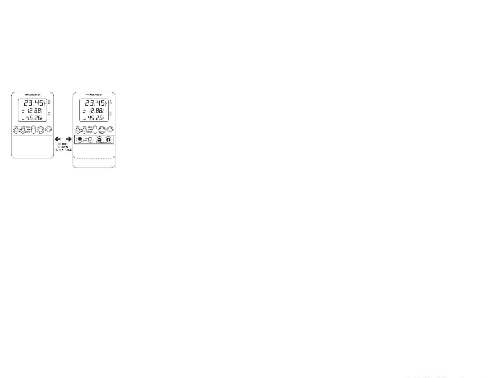
SETTING THE TIME-OF-DAY/DATE
Slide the DISPLAY switch to the DATE TIME position, the
display will show the time-of-day and date.
While in the time-of-day/date display, pressing the SELECT
button will allow the date and time to be set. Pressing
the SELECT button will cause the digits to ash in the
following order Year→Month→Day→Hours→Minutes
→12/24 hour time→No digits ashing (value set). Once
the desired item is ashing, pressing the ADVANCE button
will increment the value.
While in the time-of-day/date display, pressing the EVENT
DATE TIME button will switch the date display between
Month/Day (M/D) and Day/Month (D/M).
With the desired time-of-day/date appearing on the display,
press the SELECT button until no digits are ashing on the
display. The time-of-day/date will be saved.
Note: While in the setting mode, if no button is pressed for
fteen (15) seconds, the unit automatically exits from the
setting mode.
VIEWING THE TIME-OF-DAY/DATE
To view the time-of-day/date, slide the DISPLAY switch to
the DATE TIME position.
DISPLAYING °F OR °C
To display the temperature readings in Fahrenheit or
Celsius, slide the °C/°F button to the desired position.
DISPLAYING PROBE 1 OR PROBE 2
Slide the PROBE switch to the desired position (1 or 2) to
display the desired temperature sensor readings.
-58.00 to 158.00 °F
±0.3 °C
0.01°
1 second (F
2 each
AST)
AAA (1.5V)
MINIMUM AND MAXIMUM MEMORY
There are four points that are automatically recorded into
memory:
• Minimum (MIN) Probe 1 (P1)
Achieved with time-of-day and date achieved
• Maximum (MAX) Probe 1 (P1)
Achieved with time-of-day and date achieved
• Minimum (MIN) Probe 2 (P2)
Achieved with time-of-day and date achieved
• Maximum (MAX) Probe 2 (P2)
Achieved with time-of-day and date achieved
Minimum and maximum temperature memories
are NOT programmable.
recorded into memory is the minimum temperature
achieved since the last time the memory was cleared.
The maximum temperature recorded into memory is
the maximum temperature achieved since the last time
the memory was cleared. The minimum and maximum
temperature memories are maintained over the period
since the memory was cleared.
Minimum and maximum memories are recorded for both
sensors regardless of the display mode.
VIEWING MIN/MAX MEMORY
1.
Slide the PROBE switch to the desired position (1 or
2) to display the desired temperature sensor readings.
Slide the DISPLAY switch to the MIN MAX position.
2.
The display will show the current temperature and
minimum/maximum memory for the selected probe.
VIEWING MIN/MAX MEMOR
1.
Slide the PROBE switch to the desired position (1 or
2) to display the desired temperature sensor readings.
2.
Slide the DISPLA
The display will show the current temperature and
minimum/maximum memory for the selected probe.
Press the EVENT
3.
temperature achieved by that probe along with the
time-of-day/date the temperature was achieved will
appear on the display (indicated by MIN and
appearing on the display).
Press the EVENT
4.
the maximum temperature achieved by that probe
along with the time-of-day/date the temperature was
achieved will appear on the display (indicated by
MAX and
Note: If no button is pressed for fteen (15) seconds,
the unit automatically returns to the current temperature
display mode.
5.
To exit from the memory display mode, press and
release the EVENT DATE TIME button until MIN or
MAX no longer appears on the display
not press any button for fteen (15) seconds.
CLEARING THE MINIMUM/MAXIMUM MEMOR
1.
Slide the PROBE switch to the desired position (1 or
2) to display the desired temperature sensor readings.
Y switch to the MIN MAX position.
DATE TIME button, the minimum
DATE TIME button a second time,
TIME appearing on the display).
Temperature
Temperature
Temperature
Temperature
The minimum temperature
Y DATE/TIME
TIME
, or simply do
Y
Slide the DISPLAY switch to the MIN MAX position.
2.
The display will show the current temperature and
minimum/maximum memory for the selected probe.
3.
Press the CLEAR MIN MAX button to clear the
minimum and maximum memories for the probe
being displayed.
ALARMS
Both temperature sensor (P1/P2) alarm limits may be set
in 0.1° increments. Probe 1 and Probe 2 alarm limits are
set independent of each other.
With the alarm switch set to the ON position:
-The unit will sound an alarm and ash the corresponding
LED (P1/P2) when the temperature measured is outside
the alarm limits that have been set (equal to or lower than
the low alarm set point, or equal to or greater than the
high alarm set point).
-The alarm will sound regardless of which sensor is being
displayed and regardless of the display mode. Example:
If Probe 1 is being displayed and the DISPLAY switch is
set to MIN MAX, but Probe 2 reaches an alarm condition,
the alarm will sound and the P2 LED will ash.
SETTING THE TEMPERATURE ALARM LIMITS
1.
Slide the PROBE switch to the desired position (1 or
2) to display the desired temperature sensor readings.
2.
Slide the DISPLA
The display will show the current temperature and
low/high alarm set points for the selected probe.
. While in the alarm display mode, pressing the SELECT
3
button will allow the alarm limits to be set.
Pressing the SELECT
ash in the following order: Low Alarm 1st Digits→Low
Alarm 2nd Digit→Low Alarm Decimal Digit→ High Alarm
1st Digits→High Alarm 2nd Digit→High Alarm Decimal
Digit→No digits ashing (value set).
4.
Once the desired item is ashing, pressing the
ANCE button will increment the value.
ADV
5.
With the desired alarm set points appearing on the
display
are ashing on the display
be saved.
Note:
for fteen (15) seconds, the unit automatically exits from
the setting mode.
VIEWING THE TEMPERATURE ALARM LIMITS
1.
2) to display the desired temperature sensor readings.
2.
The display will show the current temperature and
low/high alarm set points for the selected probe.
ENABLE/DISABLE
To enable the alarm to activate when a temperature
measured is outside the alarm limits, slide the ALARM
switch to the ON position.
, press the SELECT button until no digits
While in the setting mode, if no button is pressed
Slide the PROBE switch to the desired position (1 or
Slide the DISPLA
Y switch to the ALARM position.
button will cause the digits to
. The alarm settings will
Y switch to the ALARM position.
ALARMS
When the alarm is enabled, both Probe 1 and Probe 2
alarm set points will be monitored. If either sensor reaches
an alarm condition, the alarm will activate. It is not possible
to enable the alarm for one sensor and disable the alarm
for the other sensor.
To disable the alarm so that no alarm sounds when a
temperature measured is outside the alarm limits, slide
the ALARM switch to the OFF position.
ALARM SOUNDING
With the alarm enabled, the unit will sound an alarm and
the corresponding (P1/P2) red LED will ash when a
temperature being measured is outside the alarm limits
that have been set (equal to or lower than the low alarm
set point, or equal to or greater than the high alarm set
point). Until it has been acknowledged/silenced (see
the “Acknowledge/Silence An Alarm” section), the alarm
will sound and corresponding (P1/P2) red LED will ash
continuously for the rst sixty (60) seconds. After 60
seconds, the alarm will sound and LED will ash for ten
(10) seconds every minute.
If the alarm is sounding based on the low alarm limit and
the probe temperature is being displayed, “LO ALM” will
also ash on the display. If the alarm is sounding based
on the high alarm limit and the probe temperature is
being displayed, “HI ALM” will ash on the display.
The alarm will sound and corresponding LED will ash
regardless of which sensor is being displayed and
regardless of the display mode. Example: If Probe 1 is
being displayed and the DISPLAY switch is set to MIN
MAX, but Probe 2 reaches an alarm condition, the alarm
will sound and the P2 LED will ash.
The unit will continue to alarm and ash the corresponding
(P1/P2) red LED until the alarm has been acknowledged/
silenced by either pressing the SILENCE ALM button or
by sliding the ALARM switch to the OFF position (see the
“Acknowledge/Silence An Alarm” section). The unit will
continue to alarm and ash the corresponding (P1/P2) red
LED even if the temperature being measured returns to an
in-range/non-alarm condition.
ACKNOWLEDGE/SILENCE AN ALARM
While alarming, the alarm may be acknowledged/silenced
in one of the following ways:
1.
Setting the ALARM switch to the OFF position will
silence the alarm, but when it is switched back to the
ON position, if the temperature being measured is
still in an alarm condition, the alarm will sound.
Setting the
prevents any/all alarms from sounding.
2.
SILENCE
will not sound again until the temperature being
measured has returned to an in-range condition and
then goes to an alarm condition.
ALARM switch to the OFF position.
Slide the
ALARM switch to the OFF position
Press the SILENCE
ALM button. Pressing the
ALM button will silence the alarm, the alarm
Page 2
VIEWING ALARM EVENT VALUE DATE & TIME
EXAMPLE - USING THE ALARM AND MEMORY TO
When the thermometer achieves an alarm condition,
the date and time for the most recent alarm condition
is stored into memory. The most recent alarm event
achieved is stored for each probe (P1/P2) independently.
To view the most recent alarm event:
1. Slide the PROBE switch to the desired position (1 or
2) to display the desired temperature sensor readings.
2. Slide the DISPLAY switch to the ALARM position.
The display will show the current temperature and
the low/high alarm set value.
3. Press the EVENT DATE TIME button, the most recent
alarm set value that was achieved along with the
time-of-day/date the alarm occurred will appear on
the display.
Note: The value that appears at the top of the display
while displaying the event date/time, is the alarm set
value that caused the alarm condition, not the actual
temperature achieved while in the alarm condition. If
nothing appears on the display when the EVENT DATE
TIME button is pressed, this indicates that either the unit
has not achieved an alarm condition, or that the alarm set
values have been changed for the selected probe since
the unit last achieved an alarm condition.
4. To exit from the alarm event display mode, press and
release the EVENT DATE TIME button, or simply do
not press any button for fteen (15) seconds.
DISPLAY MESSAGES
LL.LL appearing on the display indicates that the
temperature being measured is outside of the
temperature range of the unit, or that the probe is
disconnected or damaged.
BENCH STAND
The unit is supplied with a bench stand that is a part
of the back of the unit. To use the bench stand, locate
the small opening at the bottom back of the unit. Place
your ngernail into the opening and ip the stand out.
To close the stand, simply snap it shut.
EXAMPLE - USING THE ALARM AND MEMORY TO
MONITOR A REFRIGERATOR/FREEZER
Following is a simple example of how to use the alarm
and memory to monitor the temperature inside a
refrigerator or freezer. This example is provided only as a
helpful guide and is not intended to replace existing facility
requirements or procedures.
In this example, the refrigerator temperature must be
monitored and logged for each 24 hour period and certain
actions must be taken if temperature falls below 0°C or
rises above 5°C at any time during the 24 hour period.
Unit Setup Example
1. Plug the probes into the unit.
2. Install the batteries.
3. Place the probe sensor inside the refrigerator.
4. Place the display outside the refrigerator.
5. Select the desired probe.
(See the “Displaying Probe 1 or Probe 2” section.)
6. Set the probe temperature low alarm limit to 0°C.
(See the “Setting The Temperature Alarm Limits”
section.)
7. Set the probe temperature high alarm limit to 5°C.
(See the “Setting The Temperature Alarm Limits”
section.)
8. Enable the alarms.
(See the “Enable/Disable Alarms” section.)
9. Clear the minimum and maximum memory.
(See the “Clearing the Minimum/Maximum Memory”
section.)
10. Slide the DISPLAY switch to the MIN MAX position.
(See the “Viewing Min/Max Memory” section.)
The alarm limits have been set and the alarm has been
enabled. The display has been set to show the current
temperature inside the refrigerator along with the minimum
and maximum temperature that has been achieved inside
the refrigerator.
If the temperature inside the refrigerator goes outside
the alarm limits (equal to or lower than the low alarm
set point, or equal to or greater than the high alarm set
point), the alarm will activate. The memory will provide
a record of the single lowest and highest temperature
achieved.
Monitoring Procedure Example
Keep a notebook or spreadsheet as a manual log.
1. At the same time every day, record the following
into the manual log:
• Current Date and Time
• Current Temperature Reading
• Minimum Temperature Reading (MIN)
• Maximum Temperature Reading (MAX)
2. Once the above items have been manually recorded,
clear the temperature memory. (See the “Clearing
the Minimum/Maximum Memory” section.)
By clearing the memory each day, the minimum
maximum temperature memory will provide a
t
he minimum and maximum temperature that has been
chieved inside the refrigerator over the past 24 hour
a
monitoring period. In addition to the alarm, th
will also allow the user to see if the temperature insid
frigerator went outside of the acceptable range.
re
ALL OPERATIONAL DIFFICULTIES
If this unit does not function properly for any reason,
replace the batteries with new high-quality batteries
(see the “Battery Replacement” section). Low battery
power can occasionally cause any number of “apparent”
operational dif culties. Replacing the batteries with new
fresh batteries will solve most dif culties.
BATTERY REPLACEMENT
Erratic readings, a faint disp
battery symbol appearing on the display are all
indications that the batteries must be replaced.
Remove the battery cover, located on the back of the
unit, by sliding it down. Remove the exhausted batteries
and replace them with two (2) new AAA alkaline batteries.
Make certain to
polarity as indicated by the illustration in the battery
compartment. Replace the battery cover.
Replacing the batteries will clear the minimum/maximum
memories, the high/low alarm settings, and the time-ofday/date.
WARRANTY, SERVICE, OR RECALIBRATION
For warranty, service, or recalibration, contact:
Control Company is ISO 9001 Quality-Certifi ed by DNV and ISO
17025 accredited as a Calibration Laboratory by A2LA.
insert the new batteries with the proper
CONTROL COMPANY
lay, no display, or a
and
record of
e memory
e the
TRACEABLE
HIGH
ACCURACY
DUAL
THERMOMETER
INSTRUCTIONS
5 Commonwealth Ave
Woburn, MA 01801
TestEquipmentDepot.com
Control Company Cat. No. 4337 / 4338
Traceable® is a registered trademark of Control Company.
2014 Control Company. 92-4337-00 Rev. 0 120214
©
®
 Loading...