

Page 1
T240
Autotransformer
Installation and Operation Guide
ã2000 Trace Engineering P/N 975-0002-01-02 Rev. B 04/00
Page 2

©2000 Trace Engineering
Page 3

T240 Autotransformer
Table of Contents
Section Description Page
1. INTRODUCTION ..................................................................... 1
2. INSTALLATION .......................................................................2
3. OPERATION ......................................................................... 18
4. SERVICE INFORMATION .................................................... 19
5. SPECIFICATIONS ................................................................ 20
6. WARRANTY ..........................................................................21
The T240 Autotransformer .................................................. 1
Installation ........................................................................... 2
Required Tools ................................................................ 2
Mounting ......................................................................... 2
Wiring .................................................................................. 4
Service Crimps ................................................................ 4
Connection Points ........................................................... 5
Step-up Configuration ..................................................... 8
Deep Well Pump Wiring ..................................................9
Step-Down Configuration .............................................. 10
Step-Down Connection of Stacked-pair Inverters ......... 11
Generator Output Balancing Autotransformer ..............12
Single 120 volt AC Load ........................................... 12
Dual 120 volt AC Loads ............................................ 13
Optional Circuit Breakers .............................................. 16
Wiring Check ................................................................. 17
©2000 Trace Engineering
i
Page 4
IMPORTANT SAFETY INSTRUCTIONS
This manual contains important safety instructions that should be followed
during the installation and maintenance of this product.
To reduce the risk of electrical shock, and to ensure the safe installation and
operation of this product, the following safety symbols have been placed
throughout this manual to indicate dangerous conditions and important safety
instructions.
WARNING - A dangerous voltage or condition exists in this area.
Use extreme caution when performing these tasks.
AVERTISSEMENT - Une tension ou condition dangereuse existe dans cette
zone.
Faire preuve dextrême prudence lors de la réalisation de ces tâches.
CAUTION - This procedure is critical to the safe installation or operation of
the unit. Follow these instructions closely.
ATTENTION - Cette procédure est essentielle à linstallation ou lutilisation
de lunité en toute sécurité. Suivre ces instructions de près.
NOTE - This statement is important. Follow instructions closely.
NOTE - Cette déclaration est importante. Suivre les instructions de près.
All electrical work must be done in accordance with local, national,
and/or international electrical codes.
Before installing or using this device, read all instructions and cautionary
markings located in the T240 and the manual.
Do not expose this unit to rain, snow or liquids of any type. This product is
designed only for indoor mounting.
To reduce the chance of short-circuits when installing or working with this
product, use insulated tools.
Remove all jewelry such as rings, bracelets, necklaces, etc., while installing
this system. This will greatly reduce the chance of accidental exposure to
live circuits.
ii
©2000 Trace Engineering
Page 5

This product contains no user-serviceable parts. Do not attempt to repair
this unit.
Do not mount this device in unventilated enclosures or in an engine
compartment.
Protect the device from splashing when used in vehicular applications.
To reduce risk of electric shock, disconnect all wiring before attempting any
maintenance or cleaning.
Additional AC disconnects may be required as part of the system installa-
tion. Consult local and national electrical code requirements.
Over-current Protection, provided by a 25 amp circuit breaker, protects the
AC input/output wiring. This circuit breaker is branch circuit rated and has a
10,000 AIC rating, suitable for residential and commercial applications.
This unit is designed to be horizontally wall mounted.
The AC input and output neutral conductors are not connected (bonded) to
the chassis.
The AC input and output HOT conductor are not isolated from each other.
The chassis housing of the T240 must be connected to a permanent
grounding system as required by the National Electric Code, ANSI/NFPA 70-
1996. This is the responsibility of the system installer. A grounding terminal
strip is provided for connection of equipment grounding conductors.
UL rated as an indoor enclosure.
UL listed for sale in the U.S. and Canada under Photovoltaic Power System
Accessaries (UL1741) and Canadian standard for general use power
supplies (CSA C22.2 No. 107.1-95).
SAVE THESE INSTRUCTIONS
©2000 Trace Engineering
iii
Page 6

Disclaimer of Liability
Since the use of this manual and the conditions or methods of installation,
operation, use and maintenance of the unit are beyond the control of Trace
Engineering, the Company does not assume responsibility and expressly
disclaims liability for loss, damage, or expense arising out of or any way
connected with such installation, operation, use, or maintenance.
iv
©2000 Trace Engineering
Page 7
1.0 INTRODUCTION
The T240 Autotransformer is designed to step-up 120 volt AC to 240 volt AC
or to step-down 240 volt AC into two 120 volt AC circuits. The T240 contains
two identical windings that can be used to step-up, step-down, or balance the
output voltage of an AC power source (such as an inverter, generator or
conventional AC source) to an AC load. The unit is sized to take advantage of
Trace Engineerings inverter/charger line. The exceptionally high efficiency of
the T240 Autotransformer makes it ideal for voltage conversion from an inverter,
generator or conventional AC source.
The T240 Autotransformer utilizes a highly-efficiency transformer constructed
of high temperature materials and M-6 grade steel laminations, meeting UL
Class-H standards.
The unit is housed in a powder coated, steel enclosure, suitable for indoor
installations and contains knockouts for 3/4 inch and 1 inch conduit connections
and additional breakers. One 25 amp dual breaker is supplied with the T240.
Up to six additional Square D QOU breakers can be added for additional input/
output wiring protection and control.
©2000 Trace Engineering
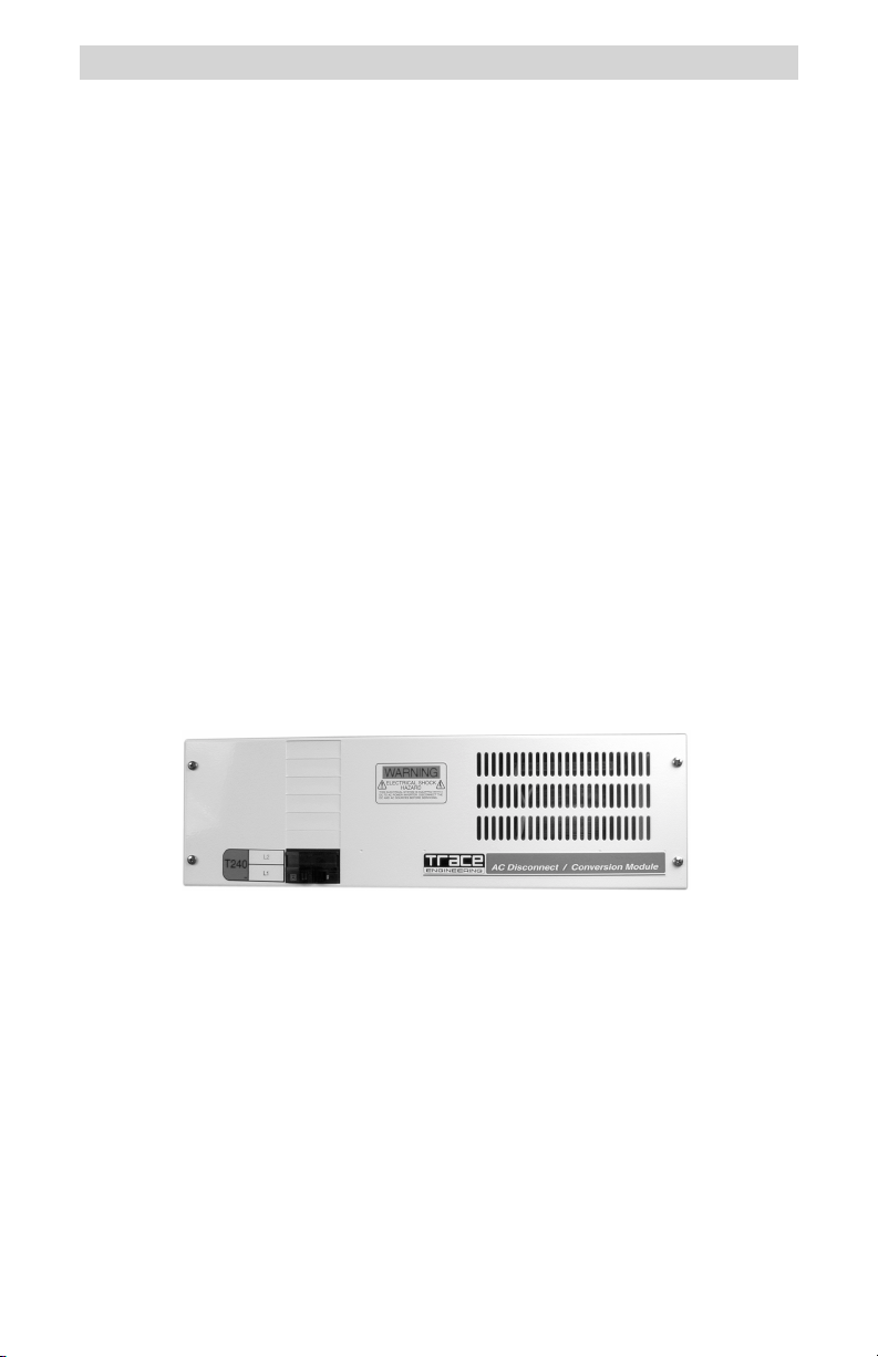
Figure 1
T240 Autotransformer
1
Page 8
2.0 INSTALLATION
Installation
Required Tools
Wire strippers
Phillips screw driver
Slotted screw driver
Torque wrench
Mounting
Place the T240 Autotransformer in a convenient location, close to the input
source (inverter, generator or utility). The T240 must be mounted horizontally
on a flat surface (such as a wall) in a clean, dry environment. Do not mount the
autotransformer where it will be exposed to the weather or in a wet location.
NOTE: The T240 weighs approximately 50 pounds. Use appropriate wall
anchors or backing material (plywood, 2 x 4s, etc.) that will support its weight.
Procedure:
Use a level and mark the location for mounting the unit on the wall.
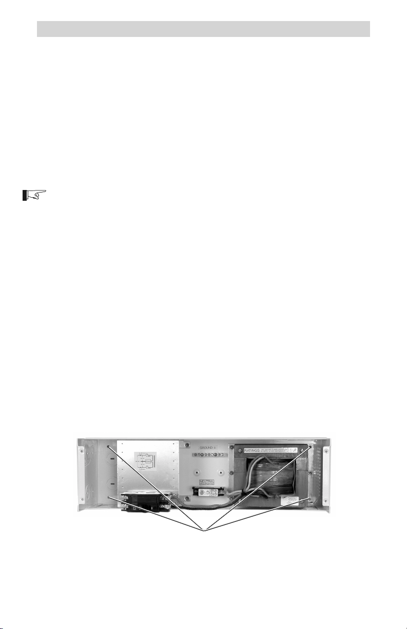
Measure out the four mounting screw holes according to Figure 3.
Drill out the mounting holes using a #18 (0.170 inch) drill bit.
Remove the front cover of the autotransformer by removing the four
Phillips screws. Do not lose the screws!
Use a #10 x 3/8 (or 1/2) inch long screw and washer (and appropriate
anchors if necessary) and mount the autotransformer securely to the wall
or backing material (plywood, 2 x 4s, etc.).
Remove the appropriate knockouts for the conduit. Install the conduit
between the autotransformer and input source (inverter, generator, etc.)
and output to load. Use separate conduit for input and output wiring.
Mounting Holes
Figure 2
Mounting Holes
2
©2000 Trace Engineering
Page 9
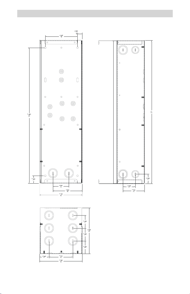
2.0 INSTALLATION
Figure 3
Installation Drawing
©2000 Trace Engineering
3
Page 10
2.0 INSTALLATION
Wiring
WARNING: WIRING SHOULD BE PERFORMED ONLY BY QUALIFIED
PERSONS.
WARNING: BEFORE WIRING THE AUTOTRANSFORMER, ENSURE THAT
ALL SOURCES OF POWER ARE DISCONNECTED. NEVER WORK ON A
LIVE CIRCUIT.
CAUTION: THE CONFIGURATION OF THE AUTOTRANSFORMER IS FOR
STEP-UP, STEP-DOWN OR CURRENT BALANCING. IT DOES NOT
PROVIDE ISOLATION BETWEEN INPUT AND OUTPUT. DO NOT USE THE
AUTOTRANSFORMER AS AN ISOLATION DEVICE.
NOTE: All source connections (inverter, generator or utility) are connected to
the left-hand side of the installed circuit breaker (see illustrations). All loads
connect to the service crimp on the right-hand side of the breaker.
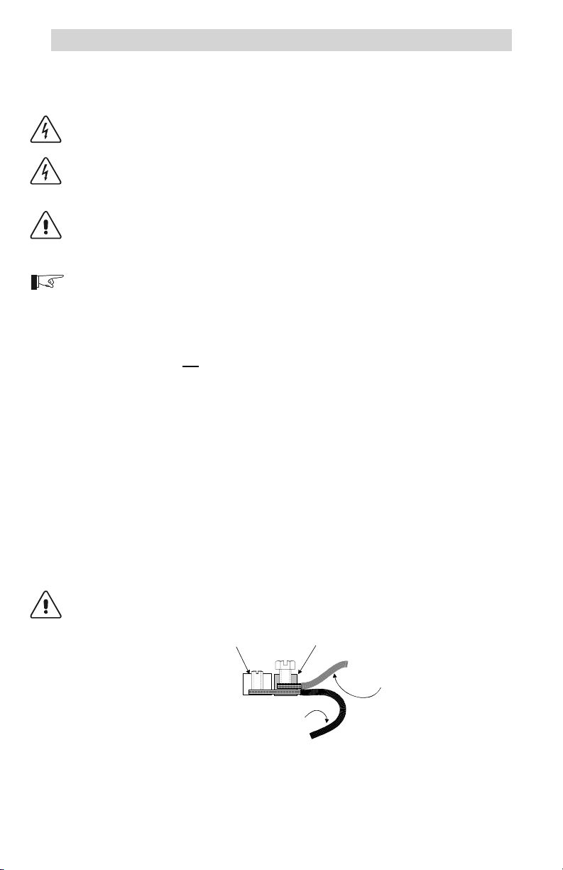
Service Crimps
The service crimps provide a convenient means to connect the
autotransformer. Do not use the screw terminals on the breakers for making
connections. Do not remove factory wiring.
Pull back the insulation on the TRANSFORMER wire so it is exposed
inside the service crimp.
Strip off approximately 1/2 inch of the insulation from the wire to be
installed and insert the bare wire into the crimp.
Slide the crimp up to the circuit breaker terminal as far as it will go.
Place the wire in the crimp and ensure the existing wires insulation is fully
exposed. Torque the crimp screw to 45 inch/pounds.
After torquing, ensure the service crimp is tight on both wires and is not
able to twist or be moved.
CAUTION: UNUSED SERVICE CRIMPS SHOULD BE TIGHTENED TO THE
EXISTING WIRE AND TAPED, SO IT CAN NOT SHORT TO OTHER
TERMINALS OR THE CASE.
Breaker Lug
Existing Factory Wiring
Service Crimp
975-C00-004
Added
LOAD
Wire
Figure 4
Installation Drawing
4
©2000 Trace Engineering
Page 11

2.0 INSTALLATION
Connection Points
The connection points for input/output wiring is as follows:
All 240 volt AC (input or output) wires connect to the left-hand side of the
breaker, points A and C (Figures 6 and 7).
All 120 volt AC wires connect to the service crimps located on the breaker,
points B and D (Figures 6 and 7).
All neutral wires connect to the NEUTRAL block in the T240.
All ground wires connect to the GROUND block in the T240.
The ganged circuit breaker used in the T240 opens both circuit breakers if
either one receives a current draw in excess of its rating (i.e., 25 amps).
Any exceptions are noted in the procedure.
NOTE: Due to continued product improvement, parts availability, etc.,
photographs used in this manual may vary slightly from actual current
production models.
GROUND block NEUTRAL block
©2000 Trace Engineering
240 Volt AC
Input/Output
Factory Wiring DO NOT
REMOVE OR ADD WIRES
TO THESE TERMINALS!
Figure 5
Step-up Configuration Connections
120 Volt AC Input/Output
service crimps
5
Page 12

2.0 INSTALLATION
Connection Identification Points (continued)
Figures 6 and 8 identify the wiring points in the T240 Autotransformer:
A Only 240 volt AC (L1) input/output connections are made on this
B This is the service crimp on the lower ganged breaker. Only 120
C Only 240 volt AC (L2) input/output connections are made on this
D This is the service crimp on the upper ganged breaker. Only
GROUND This is the ground block contained in the T240. All ground wires
NEUTRAL This is the neutral block contained in the T240. All neutral wires
circuit breaker terminal.
volt AC input/output wires connect to this service crimp.
circuit breaker terminal.
120 volt AC input/output wires connect to this service crimp.
connect to this block for both source and load.
connect to this block for both source and load (except as noted in
the procedures).
GROUND
C
A
6
D
B
Figure 6
Connection Point Identification
NEUTRAL
©2000 Trace Engineering
Page 13

2.0 INSTALLATION
D
Neutral Block
B
Service Crimp
975-S00-002A
Service Crimp
L2
L1
Upper Breaker
C
NEUTRAL
Lower Breaker
A
GROUND
Ground Block
Figure 7
Connection Point Identification Schematic
©2000 Trace Engineering
7
Page 14

2.0 INSTALLATION
Step-up Configuration
This configuration allows for a 240 volt AC load to be supplied from a
120 volt AC input source. The voltage output of the autotransformer doubles
(from 120 to 240 volts AC) and the total output current available is one half.
Procedure
The wire terminals accept wire sizes from #14 AWG to #2 AWG. Use the
proper size wire for the load connected.
120 Volt AC Input (source)
NOTE: Refer to the previous instructions on connecting wires to the service
crimp.
Connect the 120 volt AC HOT wire (from an inverter, generator or
utility) to service crimp (point B) of the breaker as shown in Figure 8.
Connect the neutral wire (from an inverter, generator or utility) to the
NEUTRAL block in the autotransformer.
Connect the ground wire (from an inverter, generator or utility) to the
GROUND block in the autotransformer.
240 Volt AC Outputs (load)
Connect a black wire from the L1 connection on the breaker (point A),
to the loads L1 connection.
Connect a red wire from the L2 connection on the breaker (point C),
to the loads L2 connection.
Connect a white wire from the NEUTRAL block in the autotransformer
to the loads neutral connection.
Connect a green wire from the GROUND block in the autotransformer
to the loads ground connection.
L2
OUT
D
G
120 VAC
Source
Ground
C
N
HOT
G
G
A
OUT
N
L1
N
NEUTRAL
Service
Crimp
B
Service Crimp
L2
N
240 VAC
Load
G
L1
975-S00-003
Figure 8
Step-up Configuration Schematic
8
©2000 Trace Engineering
Page 15

2.0 INSTALLATION
Deep Well Pump Wiring
This wiring configuration allows the control switch for the pump to be
connected between the 120 volt AC source and the HOT input of the T240. In
this arrangement, there is no transformer idle power consumption when the
switch is open and the pump is not running. The control switch can be either a
float, pressure or manual type.
Procedure
120 Volt AC Inputs (source)
NOTE: Refer to the previous instructions for connecting wires to the service
crimp on page 4 and Figure 4.
Connect the pumps control or pressure switch to the service crimp
(point B) on the lower breaker.
Connect the 120 volt AC HOT wire (from an inverter, generator, or
utility) to the free end of the control switch.
Connect the neutral wire (from an inverter, generator or utility) to the
NEUTRAL block in the autotransformer.
Connect the ground wire (from an inverter, generator or utility) to the
GROUND block in the autotransformer.
240 Volt AC Outputs (load)
Connect a black wire from the L1 connection on the breaker (point A),
to the pumps L1 connection.
Connect a red wire from the L2 connection on the breaker (point C),
to the pumps L2 connection.
Connect a white wire from the NEUTRAL block in the autotransformer
to the pumps neutral connection.
Connect a green wire from the GROUND block in the autotransformer
to the pumps ground connection.
Ground
G
Control Switch Wiring for Deep Well Pump
©2000 Trace Engineering
120 VAC
Source
G
D
N
NEUTRAL
N
Service
Crimp
Service
Crimp
B
Control Switch
L2
L2
240 VAC
G
Deep
Well
N
Pump
L1
L1
975-S00-005
L2
OUT
N
HOT
C
A
L1
OUT
Figure 9
9
Page 16

2.0 INSTALLATION
240 Volt AC Source120 Volt AC to Loads (Step-down Configuration)
This configuration allows a 120 volt AC load to be supplied from a
120/240 volt AC input source such as a utility grid. The voltage output of the
autotransformer halves (from 240 to 120 volts AC) and the total output current
available for the 120 volt AC output doubles. This arrangement is useful for
splitting the current of a battery charger between each leg of the 240 volt AC
source, reducing losses in the wiring. This is especially important in long cable
runs or when charging from a 120/240 volt AC output generator.
240 Volt AC Input (source)
Connect the L1 AC HOT wire (from the utility grid) to point A on the
lower breaker as shown in Figure 10.
Connect the L2 AC HOT wire (from the utility grid) to point C on the
upper breaker as shown in Figure 10.
Connect the neutral wire (from the utility grid) to the NEUTRAL block
in the autotransformer.
Connect the ground wire (from the utility) to the GROUND block in the
autotransformer.
120 Volt AC Output (load)
Connect a black wire from the service crimp (point B), to the loads
HOT connection.
NOTE: Refer to the previous instructions located on page 4 and Figure 4 for
connecting wires to the service crimp.
10
Connect a white wire from the NEUTRAL block in the autotransformer
to the loads neutral connection.
Connect a green wire from the GROUND block in the autotransformer
to the loads ground connection.
D
L2
120/240 VAC
Source
(grid)
G
L2
L1
*NOTE: For 240 VAC only source
installations, the neutral wire is not
N*
Ground
G
G
G
required.
120 VAC
LOAD
(inverter/
charger)
C
A
N
120 VAC HOT
OUTPUT TO LOAD
N*
NEUTRAL
N
B
975-S00-006
Service
Crimp
Service
Crimp
L1
Figure 10
Step-down Configuration Schematic
©2000 Trace Engineering
Page 17

2.0 INSTALLATION
Step-down Connection of Stacked-pair Inverters
The T240 can also be used to step down the voltage from a stacked pair of
DR or SW Series inverters. In this configuration, the neutral of the inverters
must be isolated from the neutral block of the T240 Autotransformer, or the
inverters may over-current trip when they synchronize to an AC generator. This
configuration may not be in compliance with the NEC. Consult your local and
national electrical codes for requirements. This configuration provides double
the output current at 120 volts AC.
Procedure
Inverter Inputs to T240
Connect the HOT output of Inverter #1 to point A on the lower
breaker.
Connect the HOT output of Inverter #2 to point C on the upper
breaker.
Connect the ground wire from the inverters to the GROUND block in
the T240.
T240 Output to 120 Volt AC Load
Connect the ground wire from the load to the GROUND block in the
T240.
Connect the neutral wire from the load to the NEUTRAL block in the
T240.
Connect the HOT wire (120 volt AC) from the load to the service
crimp on lower breaker (point B).
Connect the inverters as specified in the inverters operation manual
for stacked (120/240 volt AC) operation.
HOT
I
In
120 V ac Output
L2
240 VAC
N
Generator
G
L1
HOT
In
Step-down Configuration Schematic (Dual Inverters)
©2000 Trace Engineering
nverter #2
I
nverter #1
120 V ac Output
HOT
Neutral
Ground
HOT
Out
Neutral
Ground
Out
HOT
N
G
HOT
N
G
Figure 11
240 VAC
L2
D
L2
Service
C
L1
A
G
Ground
N
G
120 VAC
LOAD
(high
current)
120 VAC HOT
OUTPUT TO LOAD
G
NEUTRAL
N
B
975-S00-007A
Crimp
Service
Crimp
L1
11
Page 18

2.0 INSTALLATION
Generator Output Balancing Autotransformer
Single 120 Volt AC Load
This configuration allows the 120/240 volt AC generator output to be
equally divided (balanced) between its L1 and L2 outputs. In this example, the
generator is using both its L1 and L2 outputs to supply a high current 120 volt
AC load. Balancing the generator in this way improves generator performance
and life, plus results in higher battery charge rates.
Procedure
Connect the L1 output of the generator to the lower breaker (point A).
Connect the L2 output of the generator to the upper breaker (point C).
Connect the ground wire from the generator to the T240 GROUND block.
Connect the neutral wire from the generator to the T240 NEUTRAL block.
Connect the inverters 120 volt AC input to the service crimp on the lower
breaker (point B).
Connect a ground wire from the inverter to the GROUND block in the
T240.
Connect a neutral wire from the inverter to the NEUTRAL block in the
T240 .
Follow the instructions for wiring the inverter to the loads as specified in
the inverters operation manual.
12
©2000 Trace Engineering
Page 19

2.0 INSTALLATION
D
L2
C
Service
Crimp
L2
120/240 VAC
Generator
G
L1
G
Ground
G
N
N
A
NEUTRAL
N
Service
Crimp
B
Inverter/Charger
HOT In
Neutral In
Ground
Neutral Out
HOT Out
L1
120 VAC Loads
HOT
Neutral
Ground
975-S00-008
Figure 12
Generator Output Balancing (single 120 volt AC load)
NOTE: The ability of the T240 to balance the load depends upon the generators
windings and voltage regulation it receives on each leg. If the voltages are not
equal, or if there are other loads on the legs, then the currents in each leg will not
be equal.
To absolutely equal the load, disconnect the neutral connection of the T240 to the
generator. This un-bonds the output neutral from ground. This neutral should be
considered as a HOT wire and treated as such. This configuration may not be
compliant with the NEC, but will balance the load on the 240 volt AC side.
©2000 Trace Engineering
13
Page 20

2.0 INSTALLATION
Generator Output Balancing Autotransformer
Dual 120 Volt AC Loads
This configuration allows the 120/240 volt AC generator output to be
equally divided (balanced) between its L1 and L2 outputs. In this case, the
generator is using both its L1 and L2 outputs to supply two separate 120 volt
AC loads. If one leg of the generator is pulling a heavier load than the other,
both legs equally divide the current, thereby balancing the generators output.
Procedure
240 Volt AC Inputs From the Generator
Connect the L1 (HOT) output of the generator to the terminal on the
lower breaker (point A).
Connect the L2 (HOT) output of the generator to the terminal on the
upper breaker (point C).
Connect the ground wire from the generator to the GROUND block in
the T240.
Connect the neutral wire from the generator to the NEUTRAL block in
the T240.
120 Volt AC Outputs to Inverters or Loads
Connect the 120 volt AC input wire for Inverter #1 to the service crimp
(point B) on the lower inverter.
Connect the ground wire from the inverter #1 to the GROUND block
in the T240.
14
Connect the neutral wire from Inverter #1 to the NEUTRAL block in
the T240.
Connect the 120 volt AC input wire for Inverter #2 to the service crimp
(point D) on the upper inverter.
Connect the ground wire from the inverter #2 to the GROUND block
in the T240.
Connect the neutral wire from Inverter #1 to the NEUTRAL block in
the T240.
Connect the inverters outputs as specified in the inverters operation
manual.
©2000 Trace Engineering
Page 21

120/240 VAC
Generator
G
2.0 INSTALLATION
Inverter/Charger
HOT 120 VAC
N
G
L2
L2
L2
N
L1
G
Ground
G
G
C
A
L1
D
Service
Crimp
N
NEUTRAL
N
N
Service
Crimp
L1
B
HOT 120 VAC
N
G
or Loads
HOT In
Neutral
Ground
Inverter/Charger
or Loads
HOT In
Neutral
Ground
Generator Output Balancing (dual 120 volt AC load)
©2000 Trace Engineering
975-S00-009
Figure 13
15
Page 22

2.0 INSTALLATION
Optional Circuit Breakers
Up to six additional Square D QOU circuit breakers can be installed in the
T240 enclosure. Front panel knockouts and predrilled holes provide for easy
mounting of additional breakers.
The example below shows these additional breakers used to protect and
control six 120 volt AC loads. Different circuit configurations can be arranged
depending upon your powering needs.
N
HOT
240 VAC
Source
G
GROUND
G
120 VAC Load
120 VAC Load
L2
D
C
L2
NEUTRAL
B
A
L1
L1
120 VAC Load
120 VAC Load
120 VAC Load
120 VAC Load
G
N
HOT
G
HOT
N
G
HOT
N
G
HOT
N
G
HOT
N
G
Step Down Arrangement Using Optional Breakers
Figure 14
NOTE: Provisions for connecting the additional neutral wires may need to be
added.
NOTE: The T240 has not been listed with UL with additional breakers installed.
16
©2000 Trace Engineering
975-S00-010
Page 23

2.0 INSTALLATION
Wiring Check
Before powering the T240 Autotransformer, recheck all wiring and ensure
it is connected to the proper terminals of the breaker or service crimps. Check
that the ground and neutral connections are properly wired and tight. Use the
schematics in this manual to trace the wire connections from the source to the
T240 and to the load.
After all the wiring has been checked, install the front cover and secure it
with the four Phillips screws removed in the beginning of the installation.
©2000 Trace Engineering
17
Page 24

3.0 OPERATION
Apply power from the source to the T240 Autotransformer.
Switch the L1/L2 breaker to ON. The loads are now energized by the
T240.
NOTE: The switch on the lower breaker controls both breakers. If either breaker
receives an over-current condition, both breakers will trip.
If additional branch circuit breakers are installed, switch them to ON if
desired.
L1/L2 Circuit Breaker
18
Figure 15
Circuit Breaker Location
©2000 Trace Engineering
Page 25

4.0 SERVICE INFORMATION
Trace Engineering takes great pride in its products and makes every effort to
ensure your unit fully meets your independent powering needs.
If your product needs repair, contact our Service department at: (360) 4358826 ext. 2223 to obtain an RMA# and shipping information; or fax this page with
the following information to: (360) 474-0616 or e-mail to:
tracewarranty@traceengineering.com.
Please provide:
Model Number: ________________________________________
Serial Number: (if applicable) _____________________________
Purchase Date: ________________________________________
Problem: _____________________________________________
_____________________________________________________
_____________________________________________________
Include a telephone number where you can be reached during business
hours and a complete return shipping address (P.O. Box numbers are not
acceptable).
Name: _______________________________________________
Address: _____________________________________________
City: _________________________________________________
State / Province: _______________________________________
Zip / Postal Code: ______________________________________
Phone: ( ) _________________________________________
Country: _____________________________________________
Register On-line
On-line warranty registration is available at: www.traceengineering.com/technical/
warranty.
visit our website at: www.traceengineering.com
©2000 Trace Engineering
19
Page 26

5.0 SPECIFICATIONS
Total P ow er R ating
Input/Output Voltage
Input/Output Frequency
Idle Power Consumption
Input/Output Circuit Breaker Rating
Weight
Shipping Weigh t
Dimensions
Enclosure
Hookup Wire Size
Conduit Sizes
Insertion Loss
Approvals
Specifications @ 25 °C
Specifications subject to change without notice
3900 VA continuous
120/240 volts AC ± 10%
60 Hz
< 12 W (typical)
25 A 2 pole Square D QOU Branch
Circuit Rated/10,0 00 AIC
39.4 lb (17.9 kg)
43.7 lb (19.8 kg)
6.3" H x 21" W x 7.0" D
(16 cm x 53.3 cm x 17.8 cm)
Indoor, ventilated, steel chassis,
powder coated white
#14 AWG to #2 AWG
Knockouts for 3/4" and 1" conduit
< 4 VAC at 3900 VA
UL1741, CSA C22.2 No. 107.1-95
20
©2000 Trace Engineering
Page 27

6.0 WARRANTY
Limited Warranty
Trace Engineering warrants its power products against defects in materials and
workmanship for a period of two (2) years from the date of purchase, established by
proof of purchase or formal warranty registration, and extends this warranty to all
purchasers or owners of the product during the warranty period. Trace does not
warrant its products from any and all defects:
arising out of material or workmanship not provided by Trace Engineering or
its Authorized Service Centers;
when the product is installed or exposed to an unsuitable environment as
evidenced by generalized corrosion or biological infestation;
resulting from abnormal use of the product or use in violation of the instructions;
in components, parts, or products expressly warranted by another manufacturer.
Trace Engineering agrees to supply all parts and labor to repair or replace
defects covered by this warranty with parts or products of original or improved design,
at the company's option. Trace Engineering also reserves the right to improve the
design of its products without obligation to modify or upgrade those previously
manufactured. Defective products must be returned to Trace Engineering or its
Authorized Service Center in the original packaging or equivalent. The cost of
transportation and insurance on items returned for service is the responsibility of the
customer. Return transportation (UPS Ground or equivalent) as well as insurance on
all repaired items is paid by Trace Engineering.
All remedies and the measure of damages are limited to the above. Trace
Engineering shall in no event be liable for consequential, incidental, contingent, or
special damages, even if Trace Engineering has been advised of the possibility of
such damages. Any and all other warranties, expressed or implied, arising by law,
course of dealing, course of performance, usage of trade or otherwise, including, but
not limited to, implied warranties of merchantability and fitness for a particular
purpose, are limited in duration for a period of two (2) years from the original date of
purchase.
Some states or counties do not allow limitations on the term of an implied
warranty, or the exclusion or limitation of incidental or consequential damage, which
means the limitations and exclusions of this warranty may not apply to you. Even
though this warranty gives you specific legal rights, you may also have other rights
which vary from state to state.
5916 - 195th Street N.E., Arlington, WA 98223 Phone: (360) 435-8826 Fax: (360) 435-2229
visit our website at: www.traceengineering.com
©2000 Trace Engineering
21
Page 28

Page 29

Page 30

Page 31

Page 32

5916 - 195th Street N.E., Arlington, WA 98223 Phone: (360) 435-8826 Fax: (360) 435-2229
visit our website at: www.traceengineering.com
 Loading...