

Trace Sun Tie ST1000, Sun Tie ST1500, Sun Tie ST2000, Sun Tie ST2500 Installation And Operator's Manual
Page 1
Sun Tie
ST1000, ST1500, ST2000 and ST2500
Inverter
Installation and Operators Manual
ã
2000 Xantrex/Trace Engineering
975-0003-01-02 Rev. A 11/00
Page 2

Page 3

Sun Tie Inverter
ST1000, ST1500, ST2000 and ST2500
Table of Contents
Section Description Page
1.0 INTRODUCTION .....................................................................................1
Standard Features ........................................................................... 1
2.0 INSTALLATION....................................................................................... 2
Pre-Installation ................................................................................2
Tools Required ..........................................................................2
Hardware/Materials Required .................................................. 2
AC Connections ........................................................................ 2
DC Connections ........................................................................ 3
ST1500 and ST2500 ............................................................ 3
ST1000 and ST2500 ............................................................ 4
Grounding ................................................................................. 5
AC Grounding .....................................................................5
DC Grounding .....................................................................5
PV Arrays ...................................................................................5
AC Circuit Breakers .................................................................. 6
Wire Routing ............................................................................. 6
Mounting .......................................................................................... 7
Wiring ........................................................................................... 11
DC Wiring ................................................................................ 11
PV Array ................................................................................... 11
ST1500 and ST2500 DC Wiring ....................................... 11
PV Array Conduit/Wire Run .............................................11
ST1000 and ST2000 DC Wiring .......................................13
PV Array Conduit/Wire Run .............................................13
AC Wiring ................................................................................ 14
Lightning Protection ...............................................................17
3.0 OPERATION ......................................................................................... 18
Start-up Procedure ........................................................................18
Required Equipment ...............................................................18
AC Utility Voltage Check ........................................................ 18
Solar Array DC Voltage Check ............................................... 19
Operational Test ...................................................................... 20
4.0 TROUBLESHOOTING ..........................................................................24
5.0 SPECIFICATIONS .................................................................................27
6.0 SERVICE INFORMATION .....................................................................28
7.0 WARRANTY.......................................................................................... 29
©2000 Xantrex/Trace Engineering
i
Page 4

Disclaimer of Liability
Since the use of this manual and the conditions or methods of installation, operation, use and
maintenance of the unit are beyond the control of Xantrex/Trace, the company does not assume
responsibility and expressly disclaims liability for loss, damage, or expense arising out of or any way
connected with such installation, operation, use, or maintenance.
ii
©2000 Xantrex/Trace Engineering
Page 5
IMPORTANT SAFETY INSTRUCTIONS
This manual contains important safety instructions that should be followed during the installation
and maintenance of this product.
To reduce the risk of electrical shock, and to ensure the safe installation and operation of this
product, the following safety symbols have been placed throughout this manual to indicate
dangerous conditions and important safety instructions.
WARNING - A dangerous voltage or condition exists in this area.
Use extreme caution when performing these tasks.
AVERTISSEMENT - Une tension ou condition dangereuse existe dans cette zone.
Faire preuve dextrême prudence lors de la réalisation de ces tâches.
CAUTION - This procedure is critical to the safe installation or operation of the unit. Follow these
instructions closely.
ATTENTION - Cette procédure est essentielle à linstallation ou lutilisation
de lunité en toute sécurité. Suivre ces instructions de près.
NOTE - This statement is important. Follow instructions closely.
NOTE - Cette déclaration est importante. Suivre les instructions de près.
All electrical work must be done in accordance with local and national electrical codes.
Before installing or using this device, read all instructions and cautionary markings located in
(or on) the manual, the ST and the PV array.
Do not expose this unit to rain, snow or liquids of any type without the rain/weather shield
hood installed (optional on some models).
To reduce the chance of short-circuits when installing or working with the inverter or the PV
array, use insulated tools.
Remove all jewelry such as rings, bracelets, necklaces, etc., prior to installing this system.
This will greatly reduce the chance of accidental exposure to live circuits.
The ST unit contains more than one live circuit (PV array and AC line). Power may be present
at more than one source even when the circuit breakers are off.
This product contains no user serviceable parts. Return the unit to a Trace Authorized Service
Center for maintenance.
Wiring to the utility should only be done after receiving prior approval from the utility company
and performed only by a qualified electrician.
Completely cover the surface of all PV arrays with an opaque (dark) material BEFORE wiring
them. PV arrays produce electrical energy when exposed to light, and could create a
hazardous condition.
SAVE THESE INSTRUCTIONS
©2000 Xantrex/Trace Engineering
iii
Page 6
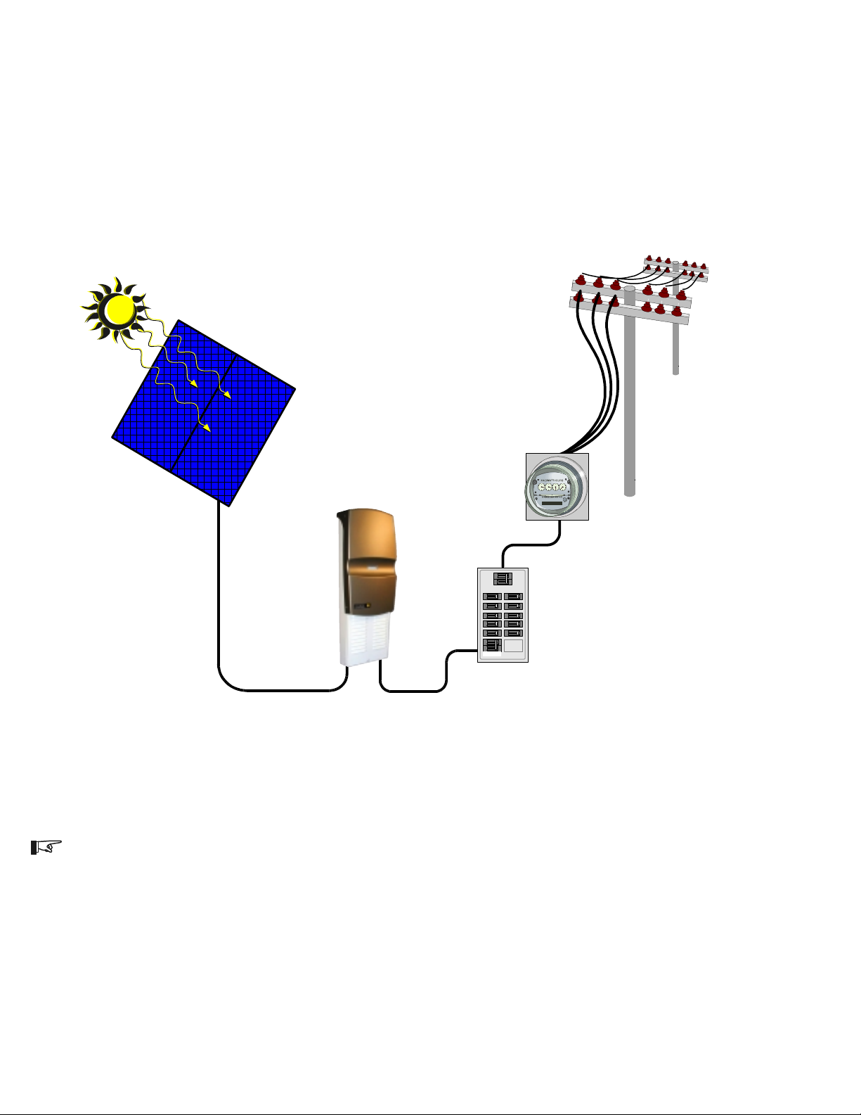
Solar PV Array
DC Input Voltage
Sun Tie Unit
AC Output
Voltage
OFF
OFF
OFF
OFF
OFF
OFF
OFF
Sun Tie
OFF
OFF
ON
ON
ON
ON
ON
ON
ON
ON
ON
OFF
ON
OFF
ON
OFF
ON
ON
OFF
OFF
ON
Solar Power
AC to Grid
AC Utility
Meter
Main Utility
Service Panel
975-F00-008SA
NOTE: This is a one line drawing intended as a system overview only. System grounding and other
electrical details are not included.
iv
©2000 Xantrex/Trace Engineering
Page 7

1.0 INTRODUCTION
The Trace Sun Tie (ST) solar power conversion center is designed to convert a home or
business into a green power generating station. The ST unit converts solar electric (PV) power into
utility grade electricity which can be used by the home, or sold to the power company. Installing an
ST unit is as simple as mounting it to the wall and connecting a DC source (PV array), and the AC
output to the utility.
Standard Features
All-in-one Design
All necessary DC input and AC output connections, disconnects and circuit breakers are housed
within the STs easily installed, compact enclosure. A built-in LCD panel provides easy-to-read
system status and daily cumulative energy production information.
Uses Most Types of PV Technology
The ST is designed to take advantage of most types of solar electric technologies. The inverter
allows up to 120 VDC open circuit PV modules to be used so both crystalline and thin film PV
modules can be used.
Maximum Power Point Tracking
The inverter performs a power sweep every minute adjusting array voltage and current,
maximizing PV power generation. Maximum Power Point Tracking (MPPT) ensures the system
produces as much AC power as possible under any light condition.
High Efficiency and Long Life
The high frequency, solid-state design of the ST inverter is extremely efficient. When array
output is over 500 watts, the inversion process is over 90% efficient (with a peak efficiency of 94%).
The ST inverter has a design life of over twenty years.
Expandable
ST inverters may be connected in a parallel configuration for increasing net metering capacity.
The modular expandability of the ST Series allows for system growth.
UL Listed
The ST has complete on-board islanding protection and meets safety operating standards and
code requirements world wide. In North America, it is UL listed (UL 1741-First Edition) and cUL listed
to CSA C22.2 No. 107.1-95. NEC 690 building code requirements for PV may be met with the
optional ground fault protection (PVGFP).
Options
These features are included on some models:
PV array combiner board with six 20 amp max. protected inputs
PV array Ground Fault Protection PVGFP
©2000 Xantrex/Trace Engineering
1
Page 8
2.0 INSTALLATION
Pre-Installation
Before installing the Trace ST unit, read all instructions and cautionary markings located in
this manual, on the PV array and on the main service panel.
NOTE: The Trace ST weighs approximately 35 pounds (depending upon configuration and model).
Always use proper lifting techniques during installation to prevent personal injury.
Mounting:
The Trace ST unit can be mounted outdoors with the optional Rain Shield (STRS).
Tools required:
Phillips screw drivers level
slotted screw drivers wire strippers
open-end wrenches torque wrench
socket wrench and fittings electrical tape
multimeter (true rms) pencil
frequency counter (optional) utility knife
Hardware/Materials required:
wood screws and washers (supplied)
conduit and appropriate fittings
anchors for screws (material dependent)
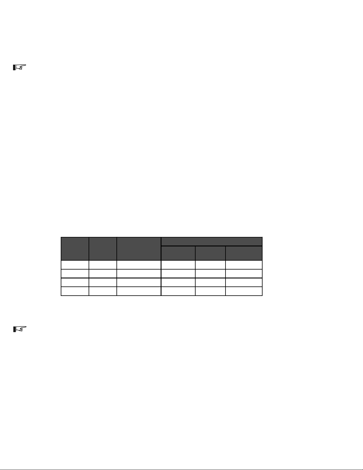
AC Connections:
The inverters AC output breakers accept wire sizes from #614 AWG. Refer to the table
below for minimum recommended wire size.
Inverter
Model
ST1000
ST1500
ST2000
ST2500
AC Am ps
Output per
leg
4.2 5.2 14 AWG 14 AWG 12 AWG
6.3 7.8 14 AWG 12 AWG 10 AWG
8.3 10.4 14 AWG 12 AWG 10 AWG
10.4 13 14 AWG 12 AWG 8 AWG
NEC Amp
(Amps *125%)
Recommended Minimum AC Wire Sizes
Minimum Wire Size for Specified Distance
0–50 Ft
One Way
50–100 Ft
One Way
100–200 Ft
Table 1
One Wa y
975-000-001
NOTE: These are the minimum recommended wire sizes in conduit. Installing a large number of
wires in conduit or enclosed locations may require larger wire sizes. Consult your local/national
electrical code for more information.
2
©2000 Xantrex/Trace Engineering
Page 9
2.0 INSTALLATION
Pre-Installation (continued)
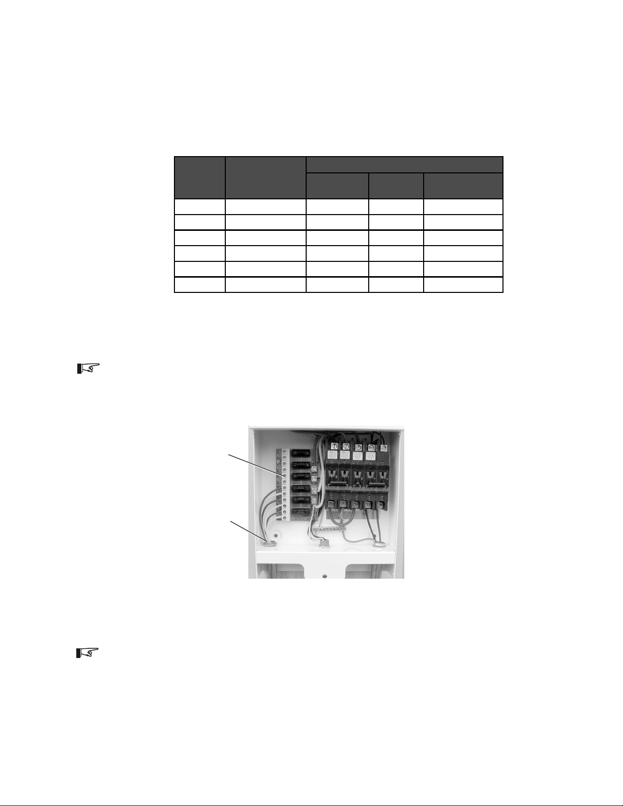
DC Connections:
ST1500 and ST2500
DC connections are made on the combiner board for models ST1500 and ST2500. The
combiner board accepts wire sizes from #614 AWG. Refer to the table below for minimum
recommended wire sizes.
DC Amps
1.0 1.6 14 AWG 14 AWG 14 AWG
3.0 4.7 14 AWG 12 AWG 10 AW G
5.0 7.8 12 AWG 10 AWG 6 AW G
7.0 10.9 12 AWG 8 AWG 6 AWG
9.0 14.0 10 AWG 8 AWG Not Recommended
11.0 17.2 10 AWG 6 AWG Not Recommended
NEC Amp
(Amps x 156%)
Minimu m W ire S ize fo r Spe c ifie d Dista n ce
0–25 Ft
One Way
25–50 Ft
One Way
50–100 Ft
One Way
975-000-002
Table 2
Recommended Minimum DC Wire Sizes
NOTE: These are the minimum recommended wire sizes. Installing a large number of wires in
conduit or enclosed locations may require larger wire sizes. Consult your local/national electrical
code for more information.
PV array wiring
(note polarity)
DC conduit wiring
(from solar arrays)
Figure 1
Combiner Board Indicating DC PV Array Wire Connection Points
NOTE: The National Electrical Code (NEC) places restrictions on minimum DC wire bending radius.
A #6 AWG wire is the largest that may be used on the ST1500 and ST2500 inverters.
©2000 Xantrex/Trace Engineering
3
Page 10
2.0 INSTALLATION
Pre-Installation (continued)
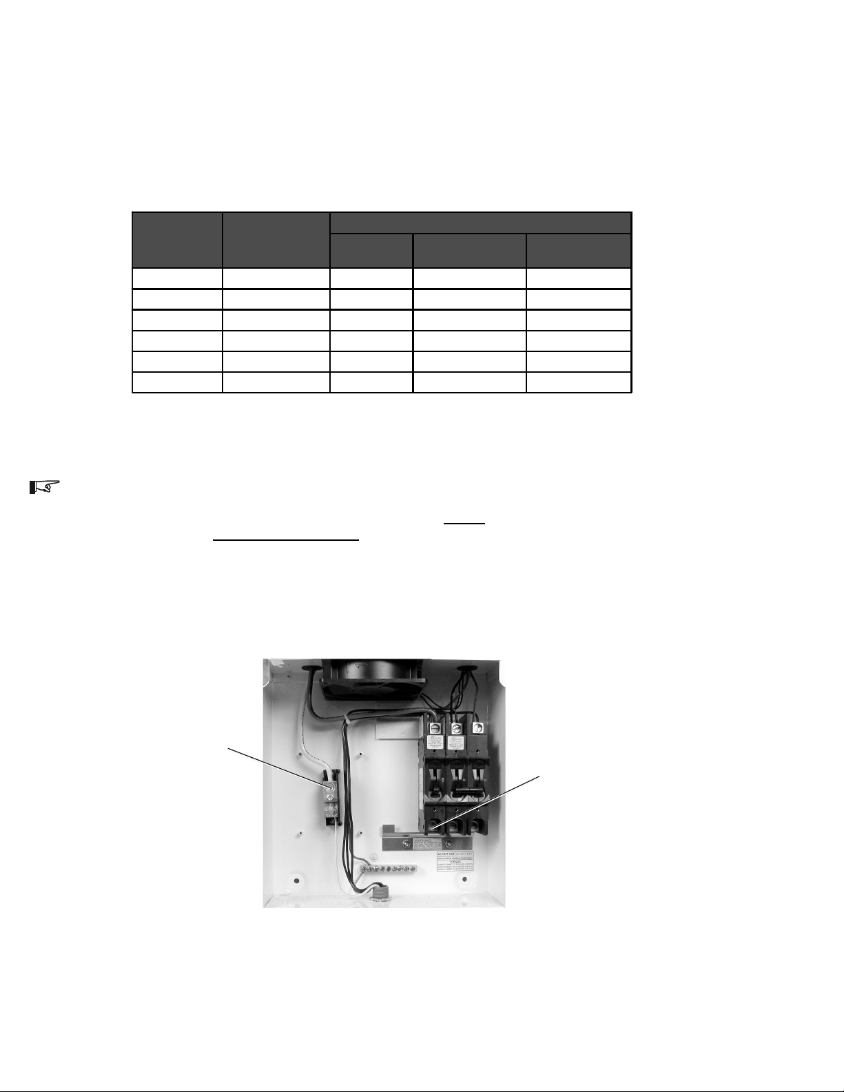
DC Connections:
ST1000 and ST2000
DC connections are made at the 100 amp DC circuit breaker and the DC negative terminal
block for models ST1000 and ST2000. Refer to the table below for minimum recommended wire
sizes.
DC Amps
(from PV array)
10 15.6 10 AWG 6 AWG 4 AWG
15 23.4 8 AWG 4 AWG *2 AWG
20 31.2 6 AWG 4 AWG *1 AWG
30 46.8 4 AWG *2 AWG Not Recommended
40 62.4 4 AWG *1 AWG Not Recommended
60 93.6 *2 AWG Not Recommended Not Recommended
NEC Amp
(Amps x 156% )
Minimum Wire Size for Specified Distance
0–25 Ft
One Way
25–50 Ft One Way
50–100 Ft
One Way
975-000-004
Table 3
Recommended Minimum DC Wire Sizes
*NOTE: The National Electrical Code (NEC) places restrictions on minimum DC wire bending radius.
If the enclosures side is used for routing the wires to the DC terminals, then the wires must be bent
to make the appropriate connections. A #3 AWG wire is the largest that may be used on the ST1000
and ST2000 inverters if the side panel is used. Side knockouts are NOT provided on the unit.
PV array Negative wiring
PV array Positive wiring
Figure 2
DC PV Array Wire Connection Points
(with no combiner board)
4
©2000 Xantrex/Trace Engineering
Page 11
2.0 INSTALLATION
Pre-Installation (continued)
Grounding:
AC Grounding
The Trace ST unit should be connected to a grounded, permanent wiring system.
DC Grounding
The negative PV conductor should be bonded to the grounding system at only one point in the
system. The size for the conductor is usually based on the size of the largest conductor in the DC
system. Negative/ground bonding is accomplished by factory wired PVGFP breakers (when this
option is installed) or a factory installed grounding block (when PVGFP is not installed).
PV Arrays:
The ST unit is optimized to work with 4-each, 12 volt nominal crystalline PV modules in series
(48 VDC nominal), or various combinations of amorphous, thin film PV modules. Ensure the PV
array used in the system operates within the MPPT operational window.
The solar array connected to the ST Series inverter should have a minimum of 50 volts DC
open-circuit in full sunlight conditions. Crystalline solar arrays configured for 48 volts DC nominal will
have a open-circuit voltage in the area of 84 volts DC in full sunlight. The maximum peak power
tracking (MPPT) software controls the output of the solar modules, under loaded conditions, in the
42-85 volts DC range (full inverter output power occurs between 5285 VDC). Other array voltage
will either not operate the inverter or will not allow maximum harvest of the suns energy.
WARNING: WHENEVER A PV ARRAY IS EXPOSED TO SUNLIGHT, A SHOCK HAZARD EXISTS
AT THE OUTPUT CABLES OR EXPOSED TERMINALS. TO REDUCE THE RISK OF SHOCK
DURING INSTALLATION, COVER THE ARRAY WITH AN OPAQUE (DARK) MATERIAL BEFORE
MAKING ANY CONNECTIONS.
ST1000 and ST2000 Models
ST1500 and ST2500 Models
©2000 Xantrex/Trace Engineering
Ground Bar Location
(connect to solid earth ground)
Figure 3
Ground Bar Location
5
Page 12
2.0 INSTALLATION
AC Circuit Breakers:
The main service panel must dedicate a 15 amp minimum, double pole breaker (120/240 volts
AC) to operate the ST unit.
Wire Routing:
Determine all wire routes both to and from the Sun Tie. Possible routing considerations include:
AC input wiring from the main service panel to the ST
DC input wiring from the PV array to the ST
DC ground from the PV array to an external ground rod
All wiring and installation methods should conform to applicable electrical and building codes.
Pre-plan the wire and conduit runs. The DC terminal blocks accept up to a #6 AWG wire
(ST1500 and ST2500) and #2 AWG* wire (ST1000 and ST2000); the AC circuit disconnects
accept cable sizes up to #6 AWG.
For maximum safety, run AC and DC wires/cables in (separate) conduits.
*NOTE: #2 AWG wire can only be used if the bottom knockouts are used. If punching side walls for
wire routing, the largest wire for acceptable wire bend radius is #3 AWG maximum.
WARNING: CHECK FOR EXISTING ELECTRICAL OR PLUMBING PRIOR TO DRILLING HOLES
IN THE WALLS!
6
©2000 Xantrex/Trace Engineering
Page 13

2.0 INSTALLATION
Mounting:
The ST unit must be mounted to a flat, vertical surface such as wallboard or wood siding.
Installation onto wallboard or concrete requires the use of anchors to properly hold the screws.
Outdoor installation requires the use of the optional rain shield (STRS) to prevent water from entering the unit.
WARNING: DO NOT INSTALL THE SUN TIE UNIT OUTDOORS WITHOUT THE RAIN SHIELD
HOOD. WATER ENTERING THE UNIT COULD CAUSE A DANGEROUS CONDITION AND
CAUSE THE UNIT TO FAIL. FAILURE DUE TO IMPROPER INSTALLATION WILL VOID THE
WARRANTY.
Procedure
WARNING: BEFORE DRILLING HOLES TO MOUNT THE SUN TIE, ENSURE THERE ARE NO
ELECTRICAL WIRES OR PLUMBING IN THIS AREA. SINCE THIS UNIT IS INSTALLED CLOSE
TO THE UTILITY ENTRANCE OR METER, THERE MAY BE A HIGH CONCENTRATION OF
ELECTRICAL WIRES IN THE AREA.
1. Locate the area where the ST is to be installed. It should be as close to the utility service panel as
possible. The
mounted.
bottom of the unit must be at least 36 inches from the floor or ground when
2. Using a level, place the mounting bracket up to the wall (in a horizontal position) and mark the
area for the three screws (Figure 4A). To achieve the 36 inch height from the bottom of the ST
unit to the ground, mount the bracket 70 inches from the ground.
3. If required, remove the bracket and drill the holes using a #10 (0.193 inch diameter) drill bit. Drill
appropriately sized holes for anchors when installing on non-wood surfaces.
4. Mount the bracket to the wall using the screws and washers provided. If mounting to other than a
wood wall or surface, use appropriate screws and anchors if required.
5. Place the Sun Ties rear lip, located on the back top of the enclosure, over the bracket and
ensure it is seated properly (Figure 4B).
6. Remove the lower external cover to access the internal circuit breaker panel by removing the
screw on each side of the cover (Figure 5).
7. Remove the internal breaker panel by removing the screws in the breakers and two screws from
the underside of the unit, then lifting until the lower locking tabs are free, then gently pull the inner
cover outward (Figure 6). Save the screws for reinstallation.
8. After the unit is correctly seated on the upper bracket, locate the two screw holes in the bottom
(back) area of the enclosure and mark these locations on the wall (Figures 4B and 7A). Remove
the ST (if required).
9. Drill two pilot holes (as above, if required).
10. Reinstall the ST, to the bracket and secure the bottom of the unit with the wood screws and
washers provided (or appropriate screws and anchors for non-wood surfaces) and tighten
(Figures 4B and 7A).
NOTE: Mounting hardware for surfaces other than wood is not supplied.
©2000 Xantrex/Trace Engineering
7
Page 14

2.0 INSTALLATION
Mounting: (continued)
Sun Tie back view
Wall Bracket, screws
and washers
(supplied)
Mount 70 inches from ground
Screw
holes
4068-E00-001
9 - 41/64"
4 - 13/16"
Enclosure
mounted on wall
bracket
8 - 55/64"
Figure 4A
Bracket Mounting
Slide ST enclosure lip onto bracket
19/64"
26 - 21/32"
3.20"
4068-E00-002
Figure 4B
Enclosure Mounting
8
©2000 Xantrex/Trace Engineering
Page 15

Upper cover
Remove screws
(one on each side)
External breaker cover
(remove during installation)
2.0 INSTALLATION
Remove screws
from tabs
Locking tabs
Figure 5
Outer Cover Components
Remove breaker screws
Lift up and pull forward to
remove
©2000 Xantrex/Trace Engineering
Figure 6
Inner Breaker Cover
9
Page 16

2.0 INSTALLATION
PV Combiner Board
(included on some
models)
NOTE: The internal
Combiner Board is not
available on all models.
Internal mounting
holes
3-11/32"
2-1/16"
DC Conduit
AC Conduit
Figure 7A
Mounting Holes and AC DC Conduit in Customer Access Area
11-13/64"
9-15/32"
5-1/64"
Lightning Arrestor
10
27/32"
61/64"
2-13/32"
3-23/32"
61/64"
2-13/32"
3-5/32"3-5/32"
3-23/32"
975-0003-D-001
Figure 7B
Conduit Hole Locations
©2000 Xantrex/Trace Engineering
Page 17

2.0 INSTALLATION
Wiring:
DC Wiring
The combiner board (included on some models) in the ST accepts up to six individual PV array
circuits (positive and negative wires). Each circuit on the combiner board contains a fuse to protect
against over-current. Always replace this fuse with one of the same type and rating (GBB, 20 amp
maximum, ceramic type, 0.25" x 1.25").
The combiner board PV array input connection block is located in the lower section of the ST
unit.
ST1500 and ST2500 DC Wiring (Refer to Figures 8 and 9)
PV Array Conduit/Wire Run
1. Install the DC conduit from the PV arrays to the bottom of the ST unit, via one of the knockout
holes (Figures 7A and 7B).
2. Route the wires from the PV array(s) through conduit and into the lower section of the ST
enclosure (Figure 9).
NOTE: If more than one PV array is used, label the wire pairs (positive and negative) appropriately
(i.e., PV 1, PV 2, etc.).
3. Connect the positive (+) wire from the #1 array to the terminal strip labeled PV INPUT 1
POSITIVE terminal. Check that the wire is in the proper location and tighten the screw.
4. Connect the negative () wires from the PV array to the PV INPUT 1 NEGATIVE terminal.
Check that the wire is in the proper location and tighten the screw.
5. Repeat this procedure for each PV array circuit, connecting the #2 PV Positive wire to the
terminal labeled PV INPUT 2 POSITIVE, etc.
NOTE: The solar arrays do not have to connect in the order marked on the board (this is just for
reference). All solar array positives on the combiner board are joined together AFTER the fuse.
Solar DC terminal block
Solar input 1
+
-
Solar input 2
+
-
Solar input 3
+
-
Solar input 4
+
-
Solar input 5
+
-
Solar input 6
+
-
Solar DC Fuses
PVGFP (ganged)
100 amp DC breaker
PVGFP (ganged)
1 amp DC breaker
Solar array
100 amp DC breaker
L1
15 amp AC breaker
(ganged)
L2
15 amp AC breaker
(ganged)
L2 breaker
AC connection
L1 breaker
AC connection
Grounding
block
Combiner board
ST1500 and ST2500 Electrical Component Location
©2000 Xantrex/Trace Engineering
Figure 8
11
Page 18

2.0 INSTALLATION
Wiring: (continued)
PV array wiring
(note polarity)
DC conduit wiring
(from solar arrays)
Figure 9
PV Array DC Connection Points (ST1500 and ST2500)
6. Repeat this procedure for each PV array circuit, connecting the #2 PV Negative wire to the
terminal labeled PV INPUT 2 NEGATIVE, etc.
NOTE: The solar arrays do not have to connect in the order marked on the board (this is just for
reference). All solar array negatives on the combiner board are electrically tied together.
7. Torque wires according to the following table.
Wire Siz e Torque (in-lb)
14 -10 AWG 35
8 AWG 40
4 - 6 AWG 45
2 - 1/0 AWG 50
975-000-003
Table 4
Wire Torque Values
12
©2000 Xantrex/Trace Engineering
Page 19

2.0 INSTALLATION
Wiring: (continued)
ST1000 and ST2000 DC Wiring (Refer to Figure 10)
PV Array Conduit/Wire Run
1. Install the DC conduit from the PV arrays to the bottom of the ST unit, via one of the knockout
holes.
2. Route the wires from the PV array through conduit and into the lower section of the ST
enclosure.
3. Connect the positive (+) wire from the array to the 100 amp DC CIRCUIT BREAKERs lower
terminal. Check that the wire is in the proper location and tighten the screw (Figure 10).
4. Connect the negative () wire from the PV array to the DC NEGATIVE TERMINALs lower
connection. Check that the wire is in the proper location and tighten the screw (Figure 10).
5. Torque all wires according to Table 4 (previous page).
Use knockouts in lower
section of ST for installing
conduit and routing wires
PV Array DC Connection Points (ST1000 and ST2000)
©2000 Xantrex/Trace Engineering
PV Array DC Negative
(-) Wire
Figure 10
PV Array DC Positive
(+) Wire
13
Page 20

2.0 INSTALLATION
Wiring: (continued)
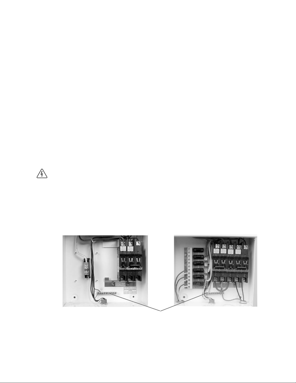
AC Wiring
AC HOT wiring is connected to the ST units L1 and L2 breakers, the ground wire connects to
the GROUND bar. All AC wiring is located in the lower section of the ST unit.
WARNING: AC UTILITY WIRING TO THE ST UNIT IS PERFORMED DIRECTLY AT THE MAIN
BREAKER PANEL. THIS SHOULD BE DONE ONLY BY A QUALIFIED UTILITY INSTALLER OR
ELECTRICIAN WITH PRIOR UTILITY COMPANY APPROVAL.
NOTE: The ST unit can be connected to a single bidirectional meter, or to dual meters, where one
meter indicates power used the second meter indicates power sold (power supplied back to the
utility). The installer and utility must determine the proper components to install.
WARNING: BEFORE WIRING THE ST UNIT, ENSURE THE MAIN 120/240 VOLT BREAKER IN
THE MAIN UTILITY BREAKER BOX IS SWITCHED OFF. SWITCH THIS BREAKER TO ON ONLY
AFTER ALL WIRING IS COMPLETED AS INSTRUCTED IN THE PROCEDURES.
1. Run conduit from the main utility breaker panel to the lower section of the ST unit. Run the
two HOT wires (L1 and L2) and ground through the conduit and into the ST units lower
section.
2. Install a dual 15 amp, ganged circuit breaker in the main utility breaker panel.
3. Connect the L1 HOT wire (black) from the 15 amp, double-pole breaker installed in the main
breaker panel, to the breaker labeled L1 in the ST unit. Refer to Figure 11A for ST1500 and
ST2500, or Figure 11B for ST1000 and ST2000 models.
4. Connect the L2 HOT wire (red) from the remaining 15 amp, double-pole breaker installed in
the main breaker panel, to the breaker labeled L2 in the ST unit.
5. Connect the ground wire (green or bare copper) from the GROUND bar in the main breaker
panel, to the GROUND bar in the lower section of the ST unit.
6. Ensure all connections are correctly wired and properly torqued.
7. Torque wires according to the following table.
Wire Size Torque (in-lb)
14 -10 AWG 35
8 AWG 40
6 AWG 45
975-0003-D-003
14
Table 5
Wire Torque Values
©2000 Xantrex/Trace Engineering
Page 21

2.0 INSTALLATION
L1
240 VAC
L2
GROUND bar
AC conduit and wiring
Figure 11A
240 V AC Connection Points (ST1500 and ST2500)
L1
240 VAC
L2
GROUND bar
240 V AC Connection Points (ST1000 and ST2000)
©2000 Xantrex/Trace Engineering
Figure 11B
15
Page 22

16
©2000 Xantrex/Trace Engineering
SOV
LIGHTNING
A
15 A
L1
15 A
L2
G
ARRESTOR
(OPTION)
L1
L2
INVERTER
G
Main
Breakers
G
L2
L1
Sun-Tie
Breakers
MAIN SERVICE PANEL
NOTES:
INSTALLER CONNECTIONS REQUIRED AT POINTS
THE INVERTER ENCLOSURE.
THE UTILITY METER MUST BE A BI-DIRECTIONAL METER.
OBTAIN UTILITY COMPAN Y APPROVAL BEFORE INSTALLING.
PVGFP AND COMBINER BOARD MAY NOT BE PRESENT ON SOME
MODELS.
(A)
AND
(B)
TO
NEUTRAL
GROUND
+
–
ST UNIT
BREAKERS (OPTION)
PV GROUND FAULT
100 A
+
–
1 A
L1
UTILITY METER
N
100 A
2.0 INSTALLATION
PV ARRAY
PV COMBINER BOARD
20 A
–
20 A
–
20 A
–
20 A
–
20 A
–
20 A
+
+
–
+
+
+
+
+
–
B
L2
L1
UTILITY
L2
N
GRID
Extra Ground Rod
Only Required on
Long Runs > 100
feet (30 m).
975-S00-003A
Figure 12
Simplified Electrical Wiring Diagram (Typical for ST1500 and ST2500)
Page 23

2.0 INSTALLATION
Lightning Protection
To protect the equipment from lightning damage, a single point grounding system should be
used. In this system, all ground lines terminate at the same point. This point normally is the main
utility ground installed by the utility company to provide a ground for the house wiring. This
ground usually consists of a copper rod driven 6 to 8 feet into the earth. Ground roof mounted
solar array frames directly to the external utility ground rod (Figure 13A).
If the solar array is located a considerable distance from the ST unit, then an additional ground
rod must be installed close to the solar array for the most reliable lightning protection (Figure
13B). The grounded frame of the solar array provides a direct route to dissipate lightning strikes
via the close ground rod. Tie this ground rod to the main utility ground rod via a heavy gauge
(#86 AWG) bare copper wire which can be buried underground. Tieing these grounds together
constitutes a single point ground and provides the best protection from lightning damage. Refer
also to the NEC for specific grounding requirements.
Solar
Array
Solar
Array
Ground
Frame to
Pole
DC Wiring
Array Ground Wire
ST Unit
Ground
Bar
> 100 feet (3 0 m)
DC Wiring
AC Wiring
Array Ground Wire
Main Utility
Breaker Panel
Ground
Bar
Bonded Neutral Wire
Utility Ground
Wire
AC
Wiring
Utility
Meter
Utility
Ground
Rod
Wiring to
Utility
Figure 13A
Typical Roof Mount Installation Grounding
Main Utility
ST Unit
Ground
Bar
AC Wiring
Breaker Panel
Ground
Bar
Bonded Neutra l Wire
Utility Ground
Wire
AC
Wiring
AC
Utility
Meter
AC
Wiring to
Utility
957-F00-007
Array Ground Rod
©2000 Xantrex/Trace Engineering
Buried Copper Wire
Utility G round Rod
975-F00-006
Figure 13B
Long Distance Grounding
17
Page 24

3.0 OPERATION
Start-up Procedure
Required Equipment
True rms reading AC voltmeter (or true rms multimeter)
DC voltmeter (or multimeter)
Frequency counter (optional)
NOTE: Before applying power to the ST unit, ensure all AC and DC wiring is correct.
AC Utility Voltage Check (Figure 14)
1. Switch ON the MAIN 240 V breakers in the main breaker service panel.
2. Ensure all circuit breakers located in the ST unit are in the OFF (down) position.
3. Switch ON the ganged 15 amp ST circuit breakers located in the main breaker service
panel. This applies the utility supplied 240 volts AC to the ST unit.
4. Using a true rms AC voltmeter, measure the AC open circuit utility voltage between L1
and L2. Ensure this voltage is approximately 240 volts AC. The inverter operates with a
line-to-line voltage (L1 to L2) ranging from 211264 volts AC.
18
Figure 14
Utility 240 Volts AC Test
CONNECT
TO L2
TERMINAL
240 VAC
AC
VOLTS
CONNECT
TERMINAL
©2000 Xantrex/Trace Engineering
DC
VOLTS
TO L1
975-U00-001a
Page 25

3.0 OPERATION
Start-up Procedure (continued)
Solar Array DC Voltage Check (Figure 15A for ST1500 and ST2500, Figure 15B for ST1000
and ST2000 models)
1. Uncover the solar arrays and expose them to full sunlight. This test can not be done
during dark or stormy weather where the available sunlight may not be intense enough to
produce the required output voltage.
2. Measure the solar array open circuit DC voltage across the DC positive (+) and negative
(-) terminals. This voltage must be greater than 50 volts DC for 5 minutes minimum to
start the inverter.
NOTE: Some thin film modules (amorphous) may produce an open circuit voltages 100-120 volts.
Crystalline solar modules will produce open circuit voltages at 75-85 volts (four modules wired in
series). An open circuit voltage 50 volts or greater is required for 5 minutes to start the inverter. The
5-minute time delay is required by safety standards.
> 50 VDC
AC
VOLTS
+
> 50 VDC
AC
VOLTS
CONNECT
POSITIVE (+)
TERMINAL
DC
VOLTS
–
CONNECT
TO
NEGATIVE (-)
TERMINAL
975-U00-002a
Figure 15A
Solar Array DC Voltage Test (ST1500 and ST2500)
CONNECT
TO
NEGATIVE (-)
TERMINAL
DC
VOLTS
+
CONNECT
POSITIVE (+)
TERMINAL
Solar Array DC Voltage Test (ST1000 and ST2000)
©2000 Xantrex/Trace Engineering
–
975-U00-002B
Figure 15B
19
Page 26

3.0 OPERATION
Start-up Procedure (continued)
Operational Test
1. Switch ON the double pole 15 amp AC circuit breakers located in the ST unit. These
breakers provide the ST produced power to the utility and provides the necessary utility
voltage and frequency to the inverter (the inverter will not produce an AC output if utility
voltage is not present on its output). Refer to Figure 16, item 1.
2. Switch ON the 100 amp DC circuit breaker located in the ST unit. This breaker supplies
the DC power from the PV array to the ST unit. Refer to Figure 16, item 2.
3. Switch the 1 and 100 amp (ganged) PVGFP breakers to ON (if installed). These breakers
open when 1 amp or greater is detected in the DC negative to ground line; indicating a
ground fault condition. Refer to Figure 16, item 3.
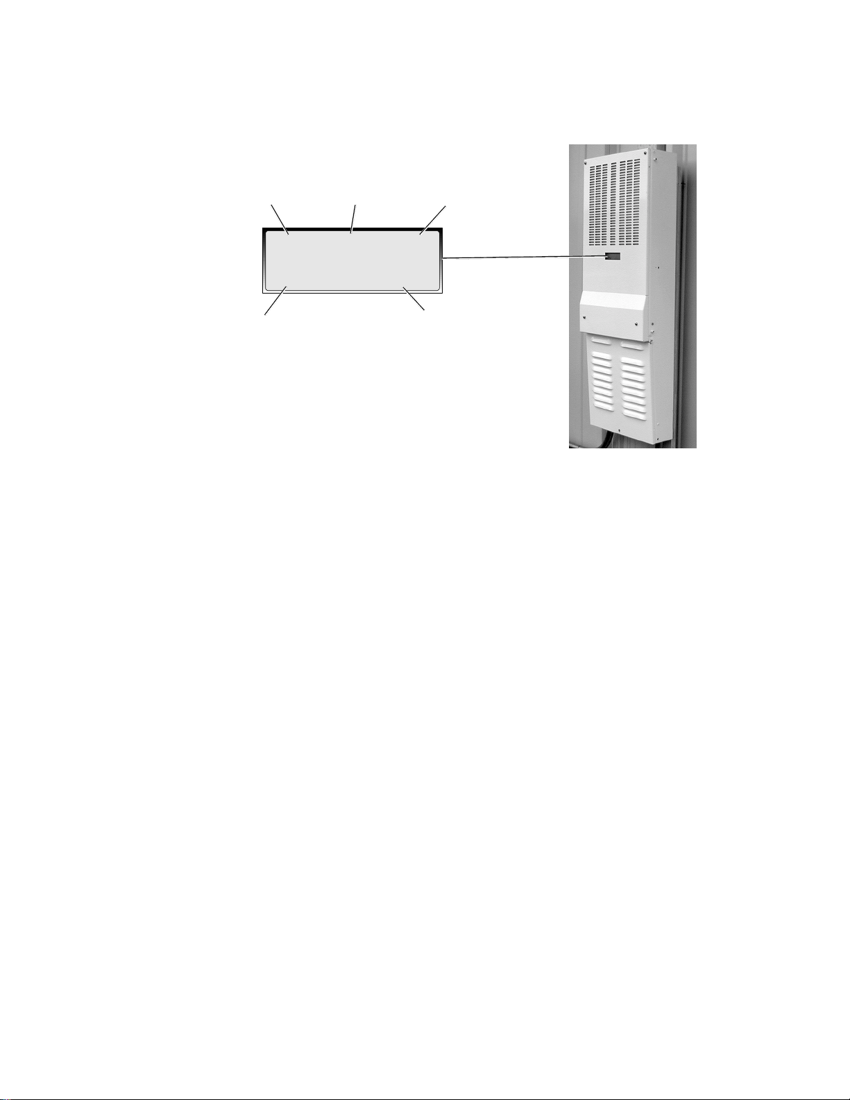
4. The inverter's Liquid Crystal Display (LCD) displays the product name, software revision,
Trace Engineering name, and finally the operational values during this sequence. During
the 5-minute timer, AC voltage, frequency, and DC voltage appear on the display (Figure
17).
23
1
20
Figure 16
Turn-On Sequence
©2000 Xantrex/Trace Engineering
Page 27
Start-up Procedure (continued)
AC Voltage Frequency Solar Array Voltage
3.0 OPERATION
240 VAC 60 Hz
2500 W 5000 Wh
Current Power
Produced
76 VDC
975-A00-001
Total Daily Power
Produced
Figure 17
LCD Location and Indications
5. View the LCD status meter and monitor the DC voltage: (Figure 17)
The inverter quickly scales up the DC solar array voltage and attempts to locate the
array's maximum power point. The DC voltage continues to increase until the CPU
detects that the maximum power point was passed.
DC voltage will be scaled down and begin increasing again to find the maximum
power point. This routine may continue several times until the maximum power point
is found. At this point the inverter will lock on to the array voltage and begin to sell the
maximum amount of power possible under the conditions. This algorithm, known as
maximum power point tracking (MPPT), operates an efficient "power sweep" once
each minute throughout the day.
Ensure the inverter begins searching for an operational DC voltage upon start-up.
After completion of the 5 minute wait protection timer, the ST begins selling power
indicated in the Watt (W) and advancing Watt-hour (Wh) meters located on the LCD
display.
©2000 Xantrex/Trace Engineering
21
Page 28

3.0 OPERATION
Start-up Procedure (continued)
6. Replace the circuit breaker panel (Figure 18).
Install the circuit breaker (inner) panel by sliding it in-place under the top cover and fitting
its two locking tabs into the slots on the bottom of the ST unit.
Reinstall the two screws located on the bottom of the unit.
Reinstall the screws on the front of the panel that secure it to the circuit breaker.
Replace screws in the
circuit breakers
Replace screws into the tabs
Figure 18
Replace Circuit Breaker Cover and Screws
7. Replace the external cover. (Figure 19).
Position the external cover in place and install a screw in each side.
NOTE: A hole at the bottom front of this cover and the main chassis allow for installing a lock to
prevent tampering or unauthorized access to the unit.
Replace screw
(one on each side)
Lock Hole
22
Figure 19
Replace Outer Cover and Screws
©2000 Xantrex/Trace Engineering
Page 29

Start-up Procedure (continued)
8. Install rain shield hood if located outdoors (Figure 20).
Install the rain shield onto the ST enclosure.
Secure it with the four screws provided (two each side).
Rain Shield
3.0 OPERATION
Install screws (2 each side)
©2000 Xantrex/Trace Engineering
Figure 20
Replace Outer Cover and Screws
23
Page 30

4.0 TROUBLESHOOTING
Troubleshooting
To aid in troubleshooting the ST units, there are two LEDs located on the CPU board accessible
after removing the upper cover panel. The LEDs light to indicate the inverters status as per the
Troubleshooting table on page 26. The upper cover should be removed only for viewing the inverter
status LEDs as dangerous voltages exist in this area. Wait five minutes after disconnecting the
inverter before removing the panel to allow the components to discharge. DO NOT REMOVE THIS
COVER FOR ANY OTHER PURPOSE.
Remove the Rain Shield (if installed) by removing the two screws (from each side) securing it
to the housing (Figure 21). Set the screws aside in a safe place.
Remove the upper external panel by removing the four screws located on the front of the
panel (Figure 21). Set the screws aside in a safe place.
Locate the red and green LEDs on the CPU board (see Figure 22).
Refer to the Troubleshooting table (on page 26) for the LED status indications.
Remove screws
Remove screws
(2 each side)
(4 total)
Figure 21
Rain Shield and Upper Panel Removal
24
©2000 Xantrex/Trace Engineering
Page 31

CPU Board
4.0 TROUBLESHOOTING
Close-up of LED area
Figure 22
CPU Board and LED Location
Green LED
Red LED
©2000 Xantrex/Trace Engineering
25
Page 32
4.0 TROUBLESHOOTING
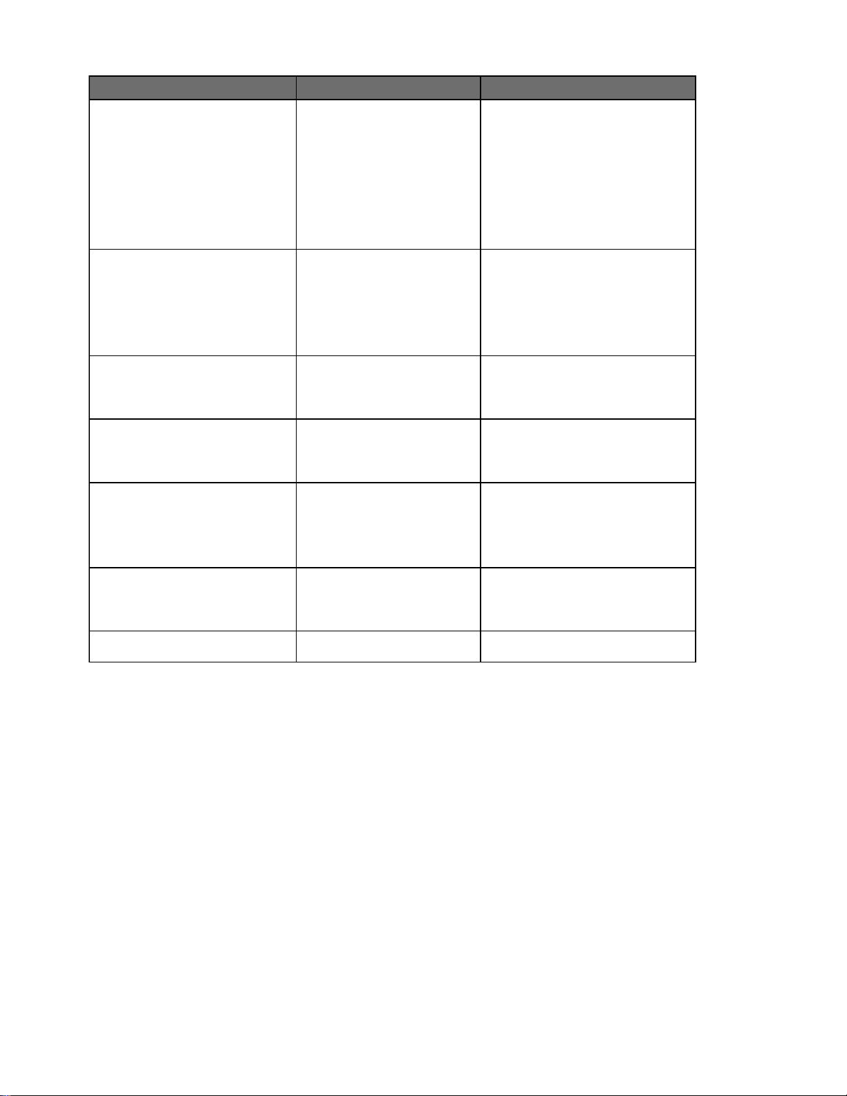
melborP esuaC ydemeR
neergroderehtetanimullitonseodUPCretrevnI
.thgilnustneiciffusnietarepotonseoddnasDEL
.FFO
dehctiwserasrekaerbCDroCA,PFGVP
.noitcesgnitarepo
ehtnidebircsedecneuqesehtnisrekaerbNOnruT
.neporognissim
.DELderehtsetanimulliylnoUPCretrevniehT
.edomdilos
.dilossetanimullireven
.DELderasehsalfneht,yliratnemom
.spirtrekaerbCDpma001 tupniCDehtsdeecxeyarraehtmorftnerruC
.spirtrekaerbPFGVP .gniriwyarraCDehtnistsixetluafdnuorgA ,gniriwreporpmirofgniriwyarraVPllakcehC
rognihsalfanisetanimullirevenDELneergehT
putratsnopuDELderehtsetanimulliretrevniehT
gnihsalfehT.edomneerggnihsalfaotniseogdna
dnasetunim5revorofseunitnocDELneerg
DELneergdilosasetanimulliUPCretrevniehT
.)s(esufdraobrenibmocpma02nepO yarraCDehtnistsixednuorgottrohsA
.langistupni
.langisCD
.egatlovCDelbatsa
.gnitarrekaerb
.gniriw
.gnitaresuf
.tneserpsiegatlovyarraCDrodirgCAoN
.tcennocsids'retrevnieht
eradraobrenibmocnoesufpma02
.esuf
CAynaezingocertonseodretrevniehT
etairporppaehtezingocertonseodretrevnI
sidirgCAehtsezingocerretrevniehT
eraycneuqerfroegatlovdirgtub,tneserp
.secnarelotetairporppaehtnihtiwton
CDdnadirgCAehtsezingocerretrevniehT
gnillestratsotstpmettadnasegatlovyarra
gnicudorptoneraslenapVPehT.rewop
taetarepootretrevniehtrofrewoptneiciffus
.gnitarrekaerbehtdeecxe
.yarraVPehtraentihekirtsgninthgilA
.rekaerbehtteser
.seriwdesopxe
ehtfossecxenitnerrucgnicudorpsiyarrA
.gnitaresufehtdeecxetonseod
.stiucrictrohsro,seriwdesopxe
siCAV042erusnednasnoitcennocCAkcehC
CDkcehC.tcennocsidCAs'retrevniehttatneserp
notneserpsiCDV521-05erusnednasnoitcennoc
rofyarraVPkcehC.sesufdraobrenibmocllatsnI
pma02ehtrofgnizisreporpmirostiucrictrohs
.NOdehctiwssitcennocsidCAretrevniehterusnE
CAerusnednaretrevniehttaegatlovCAehtkcehC
.egatlovCAehtfoecruoskcehC.tneserpsiegatlov
evitagendnaevitisopehtnoegatlovCDehtkcehC
rostlov05ebtsumegatlovCDehT.slanimrettupni
.noitareporetrevnietaitiniottiucricneporetaerg
niagayrtrosyarraVPderiwyltcerrocnirofkcehC
.ytisnetnithgilnusrethgirbhtiwyadano
ahtiwycneuqerfdnaegatlovCAehtkcehC
otrewopdirgroftiaW.retemycneuqerf/retemitlum
yfitoN.ycneuqerfro/dnaegatlovelbatpeccaotnruter
.seirdnuobetairporppaehtfoedistuo
siycneuqerffoegatlovehttahtynapmocytilitueht
evitisops'retrevniehttaegatlovtupniCDehtkcehC
tonsiyarraVPehT.slanimrettupnievitagendna
ytisnetnithgilnusroftiaW.rewophguonegnicudorp
ecudorpslenapehterusnednaesaercniot
.noitazilaitiniretrevnirofegatlovtneiciffus
tonseodtupniCDehterusnednaezisyarrakcehC
,sedoid,slenap,srekaerb,rotserragninthgilkcehC
rofstnenopmocrehtodnanoitalusnieriwCD
dnastnenopmocdegamadynaecalpeR.egamad
rogniriwreporpmirofgniriwyarraCDllakcehC
tnerructupniCDehterusnednaezisyarrakcehC
100-O-3000-579
26
©2000 Xantrex/Trace Engineering
Page 33

5.0 SPECIFICATIONS
LEDOM 0001TS 0051TS 0002TS 0052TS
lanimon–egatlovCA
egnaregatlov
egatlov
egatlovtiucric
ycneuqerflaminoN
kaep–ycneiciffE
tcennocsidCA
tcennocsidCD
yalpsidresU
epyTerusolcnE
)gnippihs(thgieW
gnitnuoM
sgnitsiL
metsys
tupnirepmumixam
noitcetorpCD/CA
.C°52@snoitacificepS
gnikcarttnioprewopmumixaM
egatlovCDtupnimuminiM
)tuptuoCAdetarllufrof(
tupniCDpu-ekawmuminiM
nepoVPmumixaMetulosbA
xam/nim–egatlovCA
scitsiretcarahctuptuoCA
xam/nim–wodniwycneuqerF
C°52@tuptuocasuounitnoC
mrofevawtuptuoCA
noitrotsidcinomrahlatoT
noitcetorpgnidnalsI
egnarerutarepmetdeificepS
)ylnoretrevni(snoisnemiD
)gnippihs(snoisnemiD
)ylnoretrevni(thgieW
noitcetorptluafdnadnuorgVP
6htiwdraobrenibmocVP
spma02.stupnidesuf
denibmoC–rotserraegruS
evitcetorP)SRTS(dleihSniaR
rofderiuqer(dleihsniar
)noitallatsniroodtuo
.ecitontuohtiwegnahcottcejbussnoitacificepS
AVk0.1AVk5.1AVk0.2AVk5.2
%29 %49
–dradnatS– dradnatS
–dradnatS– dradnatS
dradnatSdradnatSdradnatSdradnatS
lanoitpOlanoitpOlanoitpOlanoitpO
CAV042
CDV58–24
)seiresni,seludomVPCDV21lanimonruofyllacipyt(CDV25
CDV05
CDV521
CAV462–112
ecruostnerruC
zH06
tluafeDzH5.06/3.95
dellortnocMWPycneuqerfhgih,evaweniS
1471LUdna929EEEIreprewopdetarta%5nahtsseL
rekaerbdetardetiucrichcnarbCAV042,pma51elop-elbuoD
rekaerbtiucricdetarcdpma001elop-elgniS
stnemeriuqer1471LUdna929EEEIsteem–noitcetedgnidnalsievitcasulpnoitcetedycneuqerfdnaegatlovCArednu/revO
stlovCA,spmaCA–yalpsidDCLciremunahplathgilkcaB
smr
)C°54–93-(F°311–83-
deneercsylluf,erusolcnemunimuladetaocredwop,foorpniar,roodtuO
)Dmc52.31xHmc1.38xWmc8.33(D"3.5xH"52.33xW"52.31
)Dmc8.32xHmc4.49xWmc4.93(D"5.9xH"57.73xW"57.51
)gk9.51(.bl53
)gk81(.bl04
ylnotnuomllawlacitreV
59-1.701.oN2.22CASCotdetsilLUcdnanoitidets1,1471LUotdetsilLU
.decudorp)hW(dna)W(rewoptuptuo,ycneuqerfCA,stlovCD,
SNOITPODNASERUTAEFDRADNATS
200-D-3000-579
©2000 Xantrex/Trace Engineering
27
Page 34

6.0 SERVICE INFORMATION
Trace Engineering makes every effort to ensure your unit fully meets your independent powering
needs.
If your product needs repair, contact our Service department at: (360) 435-8826 to obtain an
RMA# and shipping information; or fax this page with the following information to: (360) 474-0616.
Please provide:
ST Model: _______________________________________________
Serial Number: ___________________________________________
Purchase Date: __________________________________________
Dealer/Installer: __________________________________________
Phone: ( ) ___________________________________________
Country: ________________________________________________
Problem: ________________________________________________
_______________________________________________________
_______________________________________________________
Include a telephone number where you can be reached during business hours and a complete
return shipping address (P.O. Box numbers are not acceptable).
Name: __________________________________________________
Address: ________________________________________________
City: ___________________________________________________
State / Province: __________________________________________
Zip / Postal Code: _________________________________________
Phone: ( ) ___________________________________________
Country: ________________________________________________
28
©2000 Xantrex/Trace Engineering
Page 35

7.0 WARRANTY
Limited Warranty
Xantrex/Trace Engineering warrants its power products against defects in materials and
workmanship for a period of two (2) years from the date of purchase, established by proof of
purchase or formal warranty registration, and extends this warranty to all purchasers or owners of
the product during the warranty period. Trace does not warrant its products from any and all
defects:
arising out of material or workmanship not provided by Xantrex/Trace Engineering or its
Authorized Service Centers;
when the product is installed or exposed to an unsuitable environment as evidenced by
generalized corrosion or biological infestation;
resulting from abnormal use of the product, alteration, or use in violation of the instructions;
in components, parts, or products expressly warranted by another manufacturer.
Xantrex/Trace Engineering agrees to supply all parts and labor to repair or replace defects
covered by this warranty with parts or products of original or improved design at the company's
option. Xantrex/Trace Engineering also reserves the right to improve the design of its products
without obligation to modify or upgrade those previously manufactured. Defective products must be
returned to Xantrex/Trace Engineering or its Authorized Service Center in the original packaging or
equivalent. The cost of transportation and insurance on items returned for service is the
responsibility of the customer. Return transportation (UPS Ground or equivalent) as well as
insurance on all repaired items is paid by Xantrex/Trace Engineering.
All remedies and the measure of damages are limited to the above. Xantrex/Trace Engineering
shall in no event be liable for consequential, incidental, contingent, or special damages, even if
Xantrex/Trace Engineering has been advised of the possibility of such damages. Any and all other
warranties, expressed or implied, arising by law, course of dealing, course of performance, usage of
trade or otherwise, including, but not limited to, implied warranties of merchantability and fitness for
a particular purpose, are limited in duration for a period of two (2) years from the original date of
purchase.
ome states or counties do not allow limitations on the term of an implied warranty, or the
exclusion or limitation of incidental or consequential damage, which means the limitations and
exclusions of this warranty may not apply to you. Even though this warranty gives you specific legal
rights, you may also have other rights which vary from state to state.
©2000 Xantrex/Trace Engineering
5916 - 195th Street N.E., Arlington, WA 98223 Phone: (360) 435-8826 Fax: (360) 435-2229
visit our website at: www.traceengineering.com
29
Page 36

Page 37

Page 38

Page 39

Page 40

5916 - 195th Street N.E., Arlington, WA 98223 Phone: (360) 435-8826 Fax: (360) 435-2229
visit our website at: www.traceengineering.com
 Loading...