

Page 1
TraceMeter
Battery Status Monitor
4.55”
BATTERY MONITORING SYSTEM
4.55”
BATTERY
LEVEL
%
SELECT
V
CHARGED
A
Ah
RESET
AMP HOURS
REMOVED
INVERTER
0N/OFF
INTRODUCING THE TRACE BATTERY STATUS MONITOR
The Trace Meter battery status monitor features six data-monitoring functions and three
indicators including:
!
State of Charge/Amp-hour content: full or percent of capacity
!
State of Charge/Voltage: real-time voltage level, historical high & low system
voltage
!
Amps: real-time amps, total charging amps, total load amps
!
Amp-hours removed
!
Days since fully charged
!
Cumulative amp-hours
!
Recharge indicator
!
Low voltage indicator
!
Full charge indicator
The Trace Meter works with 12-volt, 24-volt, and 48-volt battery systems
shunt board required for 48-volt systems).
Copyright Trace Engineering Co. Inc. Tel (360) 435-8826 Part Number 3507 Rev B,
a
5916 195th Street, NE Fax (360) 435-2229 January 11, 1999
Arlington, WA 98223 USA www.traceengineering.com Page
(optional TM48
1
Page 2
BASIC OPERATING FUNCTIONS
The Trace Meter enables you to monitor battery state-of-charge, voltage, amps, and amphours used. You can configure the reporting functions of the Trace Meter to your specific
application by setting the fully-charged criteria, battery capacity, charging efficiency, lowbattery warning conditions, and recharge reminder. You can monitor any DC energy supply
from zero to 65 volts, track energy consumption and estimate remaining battery life. In
addition, you can turn your Trace inverter (if equipped) On or Off remotely.
MOUNTING AND INSTALLATION
Your Trace Meter package (Part Number TM500) includes this manual, a 50-foot
communications cord, one Deltec 500-amp/50-millivolt shunt (P/N TM500NS does not
include a shunt), a 12/24-volt shunt board equipped with an in-line two-amp fuse (order
Trace part number TM48 for 48-volt systems), and a molded plastic mounting enclosure.
Mount the Trace meter in the enclosure provided or in a standard double-gang plastic
electrical box. You can surface-mount the Trace Meter on a control panel, or flush-mount it
by creating a rectangular opening 3 7/8“ wide by 3 1/4“ high to allow clearance for the
circuit board. Allow at least two inches clearance behind the meter for attaching the
cabling. Be sure to mount the Trace Meter in a clean, dry environment.
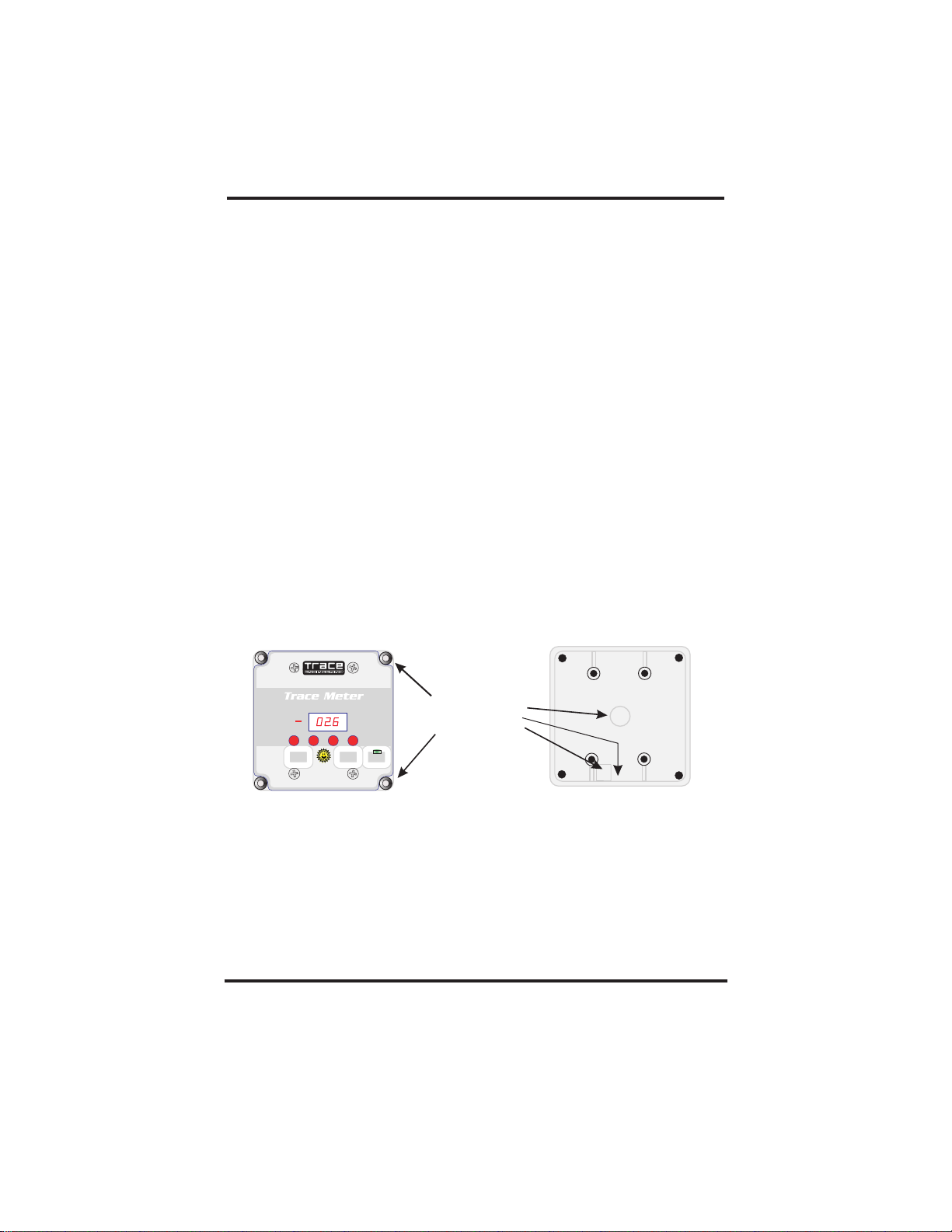
The Trace Meter faceplate with the plastic mounting enclosure is designed to allow you to
choose how to mount the meter. Remove the four screws on the faceplate and remove the
meter from its enclosure. Decide upon the mounting location and type: flush or surface.
For a flush mount, cut a rectangular opening 3 7/8” wide by 3 1/4” high in the surface in
which you are going to mount the meter. Carefully remove the recessed dimples at each
corner of the faceplate. Use an Exacto knife or razor knife to remove the center of each
screw plug. Ensure adequate clearance behind the meter for cables. Install your
communications cable and (if used) your remote control cable and mount in the surface you
have selected. Attach with appropriate length wood or sheet metal screws.
BATTERYMONITORING SYSTEM
BATTERY
V
%
LEVEL
SELECT
CHARGED
AMPHOURS
A
Ah
REMOVED
INVERTER
RESET
0N/OFF
Remove plugs from
access holes
For surface mounting, remove one or both of the access plugs in the bottom of the molded
plastic enclosure, and mount the enclosure on the surface of your choice by inserting a
wood or sheet metal screw in each of the holes in each corner of the enclosure. Then
install the meter in the enclosure, being careful not to over tighten the screws. Alternatively,
remove the center plug in the back of the enclosure, mount the enclosure on the surface,
attach the appropriate communication cables, and re-install the meter in the enclosure.
For flush mounting in new construction, install a standard double-gang plastic box (do not
use a metal box) on a stud in the usual manner, discard the molded plastic enclosure
provided and install the meter in the double-gang box after attaching the appropriate
communications cables.
a
Copyright Trace Engineering Co. Inc. Tel (360) 435-8826 Part Number 3507 Rev B,
5916 195th Street, NE Fax (360) 435-2229 January 11, 1999
Arlington, WA 98223 USA www.traceengineering.com Page
2
Page 3
Hookup Procedure
Mount the Deltec shunt on or near the battery box near the negative (-) battery terminal
or DC supply. The shunt is installed in the negative DC supply circuit. Disconnect the
negative battery cable at the battery or battery bank and attach it to the side of the shunt
labeled ‘Inverter’. Install a short cable of the same gauge from the negative (-) battery
terminal to the side of the shunt labeled
Remove the fuse from the fuse holder in the black (+) DC wire and attach the wire terminal
to a positive (+) battery terminal or DC supply. Insert the shunt communications cable into
the RJ6 connector on the shunt board. If desired, you can extend this cable up to 100
feet. Replace the fuse in the fuse holder.
DC Supply
‘Bat Minus.’
Inverter
or Load
Shunt
DC fuse
(-) in from
DC supply
BAT MINUS
PN3077
To order a Trace Meter without the shunt, use part number TM500NS. This kit includes a
shunt board, two 8-32 x 5/8” machine screws, and two spacers (standoffs). Attach the
shunt board to your shunt by first removing the two screws, flat washers, and lock washers
that came with your shunt. Replace the screws with the screws provided in the shunt kit.
Place a lock washer on the machine screws, then insert into the shunt board. Place a
spacer over each of the screws, and attach to the side of the shunt as shown in the
illustration below.
8-32 x 5/8” Machine Screw
Shunt Board
Copyright Trace Engineering Co. Inc. Tel (360) 435-8826 Part Number 3507 Rev B,
a
5916 195th Street, NE Fax (360) 435-2229 January 11, 1999
Arlington, WA 98223 USA www.traceengineering.com Page
INVERTER
(+) DC
(-) out to inverter
or load
Lock Washer
Standoff
Shunt
3
Page 4

To complete the installation, insert the shunt communications cable into the RJ6 telephonetype connector on the back of the Trace Meter printed circuit board (PCB). There are two
RJ6 connectors on the back of the PCB. The one near the top left of the board is the shunt
connector. The one on the lower left of the PCB is the remote control connector. Do not
confuse these two connectors. Irreversible damage to the PCB will result if the shunt
communications cable is connected to the remote control connector or vice-versa.
PN3077
BATMINUS
(-) in
INVERTER
(+) DC
(-) out
Shunt Connector
Remote Control
Connector
Back of Trace Meter
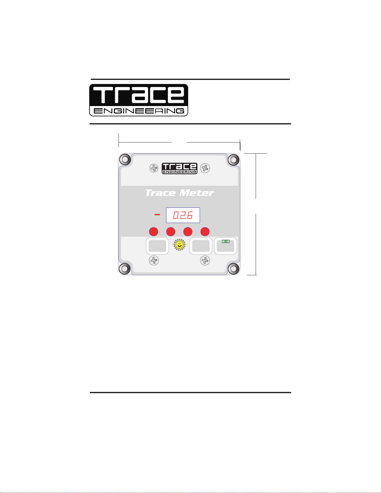
TRACE METER INDICATORS AND CONTROLS
The Trace Meter features a large three-digit LED display, four red mode indicators, one
yellow full-charge indicator, one green Inverter On/Off indicator, and three pressuresensitive pushbuttons. The LED screen displays alpha-numeric messages with resolution
to 0.00. A negative value (-) indicator is positioned just to the left of the screen.
SELECT
CHARGED
RESET
The Select button is used to switch between meters and modes. The four LEDs beneath
the screen light to indicate the operating mode: battery state-of-charge; volts, amps, and
amp-hours.
A Reset button is provided to change the user-defined parameters and to reset the fullycharged ‘Happy Sun’ indicator located between the Select and the Reset buttons.
A third button (labeled Inverter On/Off) enables you to turn your inverter On or Off remotely
if your system includes a Trace inverter/charger equipped with an RC4 or RC8 remote
control jack. The “Inverter On/Off” button duplicates the operation of the RC8 remote
control if you connect a remote control cable between the Trace Meter and your inverter.
Remote control cables are available in 10, 25, 50, and 100 foot lengths. Order Trace part
number TC/XX according to the length desired. See the RC8 Owner’s Manual (included
with the TC/XX cable) for remote control operating instructions.
INVERTER
0N/OFF
Basic Meters
To select a meter display, press and release the Select button until the desired mode
indicator lights. There are four mode indicators:
BATTERY
LEVEL
Copyright Trace Engineering Co. Inc. Tel (360) 435-8826 Part Number 3507 Rev B,
a
5916 195th Street, NE Fax (360) 435-2229 January 11, 1999
Arlington, WA 98223 USA www.traceengineering.com Page
V
%
A
Ah
AMP HOURS
REMOVED
4
Page 5
!
%
V
A
Ah
% (Percent State of Charge)
display the battery state-of-charge based upon the amp-hour capacity. Range is
LO setting(<27.5%), 30% to 90% in 5% increments, and ‘FULL’ when over 92.5%
of capacity.
!
V (Volts)
voltage from 08.0 to 35.0 volts (12 and 24 volt system) with
or 16.0 to 69.9 volts (48 volt system) with and 0.2 volt accuracy.
!
A (Amps)
current or load current in amps. The range is from ± 0.1 to ± 999 amps, with a
speed of response of one second. Accuracy is ±1.5%.
!
AH (Amp Hours)
source since the last reset. Range is from 0.00 to ±167,000 amp-hours. When
the decimal point flashes, multiply the reading by 1000. (111. = 111,000).
Automatically resets to zero about one minute after the Charge LED remains on
(stops flashing).
When this indicator is lighted, the LED screen will display the real time
When selected, the LED screen will display the real-time charge
This meter displays the total amp-hours removed from the DC
When this indicator is lighted, the LED screen will
±0.1 volt accuracy
±
Power Saving Mode
Pressing the Select button until the display goes blank puts the Trace Meter in power
saving mode. None of the red mode indicators are lighted when the meter is in powersaving mode. In this mode, the meter consumes approximately 18mA (milliamps).
Maximum power consumption in any mode is 32mA.
Data Monitors
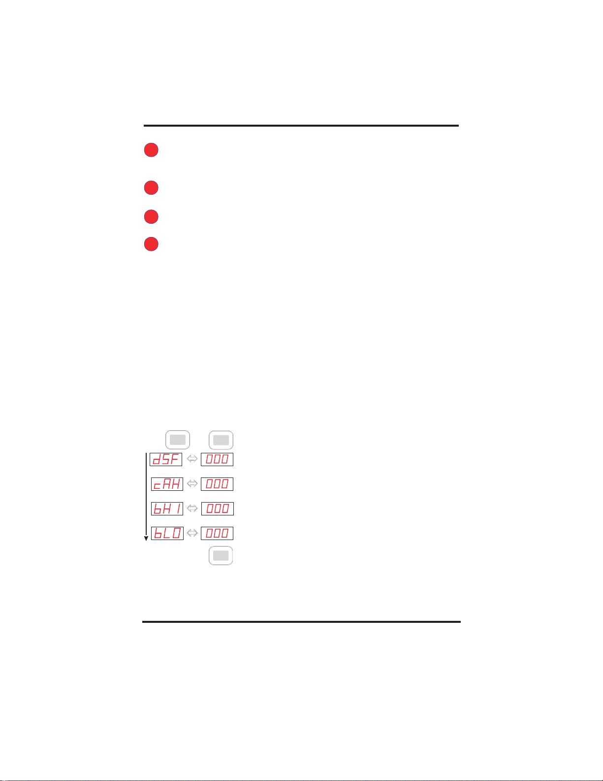
There are several additional data displays that are accessed by pressing and holding the
Select button until “dSF” is displayed on the LED. Then p
button to s The data types will alternate with the data
values.
will display the basic meters again. The data monitors are listed below in the order in
which they appear on the display.
Press
and Hold
To reset the data monitor values to zero (or present value) press and hold the Reset button
for about 5 seconds (the data monitor value will flash On and Off three times, and then
update).
croll through the data displays.
When the “bLO’ data value has been displayed, another press of the Select button
!
dSF (Days Since Full)
days since the battery was fully charged. The range is from
0.00 to 655. The value resets to zero when the battery is
recharged. (Charged LED flashes)
!
cAH (Cumulative Amp Hours)
cumulative amp-hours removed. Use it as a battery life
indicator. Its range is from 00.0 to 999,000. Multiply the
reading by1000 when the decimal point flashes on and off.
The cumulative amp-hours are retained in memory even if
the meter is disconnected.
!
bHI (High Battery Voltage)
voltage. Use to determine if an over-charge event has
occurred. Resets to current battery voltage when theTrace
Meter is disconnected and reconnected.
!
bLO (Low Battery Voltage)
Use to detect over-discharge. Resets to zero when the
Trace Meter is disconnected, then reconnected.
press &
SELECT
release
To Reset
press & hold
then
SELECT
RESET
ress and release the Select
This meter shows the number of
This meter measures the
Displays highest battery
Displays lowest battery voltage
Copyright Trace Engineering Co. Inc. Tel (360) 435-8826 Part Number 3507 Rev B,
a
5916 195th Street, NE Fax (360) 435-2229 January 11, 1999
Arlington, WA 98223 USA www.traceengineering.com Page
5
Page 6

Reminders and Other Indicators
The Trace Meter features a programmable recharge reminder, low-voltage indicator, and a
charged indicator.
Ah
interval following recharge as a reminder that it is time to charge the batteries. The range
Recharge Reminder
is from one to 99 days, or you can turn it Off. When the number of days since the last
charge exceeds the specified value, the Ah LED will flash until reset. The specified value
will be retained until the Trace Meter is disconnected.
To configure this reminder, press and hold the Select button until the dSF message is
displayed, then release. Then press and release the Select and Reset button
simultaneously. Then press the Reset button until the desired value is displayed. Press
the Select button to accept the value. Recharging the batteries synchronizes the State-ofCharge and the Amp Hour meters.
.
V
Low Voltage Indicator
and 64.9 volts for 48 volt systems) to activate the low voltage alarm. When battery voltage
falls below this setting, the Voltage indicator will flash about once every four seconds.
To configure this alarm, press and hold the Select button until the dSF message is
displayed, then release. Then press and release the Select button until the bL0 message
is displayed. Then press and release the Select and Reset button simultaneously. Press
the Reset button until the desired voltage is displayed. Accept the value by pressing the
Select button.
You can configure the Ah lamp to flash at a specified
SELECTSELECT
RESET RESET
You can specify a voltage between 10 and 35 volts (10
SELECT SELECT
CHARGED
Charged Indicator
SELECT
RESET
The yellow LED behind the ‘Happy Sun’ symbol between the
RESET
Reset and the Select buttons can be programmed to flash every four seconds when
specified charging criteria are met. You can specify voltage alone, voltage and current, or
voltage and time. When the fully-charged criteria is satisfied for 30 seconds, the Charged
LED will flash. The Charged LED will stop flashing (remains On) and the amp-hours will
reset to zero when the amps go negative (battery discharging) continuously for one minute.
To reset the Charge LED, press the Reset button while the LED is on.
SELECT
Copyright Trace Engineering Co. Inc. Tel (360) 435-8826 Part Number 3507 Rev B,
a
5916 195th Street, NE Fax (360) 435-2229 January 11, 1999
Arlington, WA 98223 USA www.traceengineering.com Page
CHARGED
RESET
%, V, or A
INVERTER
0N/OFF
6
Page 7

SETUP
The TraceMeter is factory-configured for monitoring a 12-volt DC system. You can configure
the Trace Meter for your specific application.
Reset to Factory Default Values
You can reset program values instantly by pressing and holding the Reset button when the
Trace Meter is in Power Saving mode. A flashing ‘ALL’ message will be displayed on the
LED. Hold the Reset button until the ‘ALL’ message stops flashing and the screen becomes
blank. The factory default values are shown below.
RESET
Default
Values
Low Voltage Indicator =
Recharge Reminder =
=
BATTERY
LEVEL
%
V
A
Ah
AMP HOURS
REMOVED
Setting Parameters
To set individual configuration values, press the Select button until the mode indicator for
the mode you want to change is lighted. Press the Select and the Reset button
simultaneously. Release both buttons when the LED screen begins to flash. Press and
release the Reset button to scroll through the selections slowly. Press and hold the Reset
button to scroll through the selections rapidly. When the value you want is displayed, press
the Select button to select it.
%
efficient, more energy is required to charge them than can be removed from them. Some
energy is lost in the form of heat and gassing. An efficiency factor of 94% to 98% is typical
of lead-acid batteries. This means, for example, that if you charge a lead-acid battery for
five hours @ 20 amps per hour for a total of 100 amp-hours, approximately 2% to 6% of
charge will be lost to heat and gassing. Therefore the amp-hour capacity of the battery will
increase by only 94 to 98 amp-hours. The default setting is 94%. If you have new lead-acid
batteries, set this efficiency factor to 96%. Older batteries will be less efficient. This setting
effects the Percent State-of-Charge meter.
Charge Efficiency:
Because batteries are storage devices that are not 100%
%
Copyright Trace Engineering Co. Inc. Tel (360) 435-8826 Part Number 3507 Rev B,
a
5916 195th Street, NE Fax (360) 435-2229 January 11, 1999
Arlington, WA 98223 USA www.traceengineering.com Page
SELECT
RESET
RESET
SELECTSELECT
7
Page 8
Setting the efficiency factor:
lead-acid batteries start with 94%. If you find that after discharging and recharging your
batteries that the amp-hours reading is somewhat below 000 (negative) when the Charged
LED flashes (charge settings reached), then increase the efficiency factor. If you find that
the numbers are substantially going above zero before the “charged” LED flashes,
decrease the efficiency factor. Typically, try to adjust the efficiency so that when the
“charged” LED flashes the amp-hour number is slightly positive.
If you do not know what efficiency factor to use, if you have
Ah
this mode. Determine your system’s capacity and select it. The amp-hour capacity is often
listed on the battery. If not, contact the dealer or manufacturer. This parameter is
adjustable from 10 to 2550 amp-hours. A decimal indicates a value of 1000 or over. It is
better to rate your system’s capacity conservatively in order to avoid excessively
discharging your system.
Amp Hours:
Ah
Setting the battery capacity:
that is equal to or lower than the actual capacity. When a number that is lower than the
actual capacity is used, the “%” battery state-of-charge will allow a more conservative use
of the batteries and often the stated capacity numbers for batteries tend to be optimistic.
Also note what temperature your battery capacity is rated, the amp-hour capacity of
batteries will decrease at lower than rated temperatures. If batteries are connected in
series, the capacity of the series string is equal to the value of the least capacity battery in
the series.
Set your system’s amp-hour capacity using the Setup menu under
SELECT
RESET
The battery capacity setting should be adjusted to a value
RESET
SELECTSELECT
Setup for the Charged Indicator
Use the settings described below to program the Charged indicator. Choose between
voltage, voltage and current, or voltage and time as the criteria for activating the Charged
indicator.
your charging source is less than your fully charged current setting (battery capacity
divided by 20 - C/20).
A good rule of thumb - use voltage/amperage criteria unless the peak amps from
V
release the Select button until the voltage (V) indicator is lighted, then press the Reset
Voltage Criterion
button while holding the Select button down. The screen will blink and display the present
voltage setting. Press the Reset button to select the desired full-charge voltage. Press the
Select button to accept the value. The range is from 10 to 64.9 volts. When the fullycharged criteria are satisfied, the ‘Happy Sun’ LED will flash. For 48-volt systems, set the
full-charge criterion above 35 volts, else the display value will be ½ of the actual voltage.
For a 12-volt, liquid lead-acid battery bank, 14.3 to 14.8 volts is an appropriate full-charge
voltage. For a 24-volt system, double the voltage set point. For a 48-volt system,
quadruple the setpoint. For other battery types, refer to manufacturers recommendations.
: To specify the full-charge voltage value, first press and
Copyright Trace Engineering Co. Inc. Tel (360) 435-8826 Part Number 3507 Rev B,
a
5916 195th Street, NE Fax (360) 435-2229 January 11, 1999
Arlington, WA 98223 USA www.traceengineering.com Page
8
Page 9

SELECT
V
SELECT
RESET
RESET
SELECT
A
voltage value first and then turn the amps criterion Off. Press Select to select the amps (A)
Voltage Alone:
indicator and enter the Setup menu by pressing the Reset button while holding the Select
button down. The LED display will flash on and off displaying the present amps criterion
value. Press the Reset button until ‘OFF’ is displayed, then press the Select button to
accept the value.
To specify voltage as the sole criterion, set the fully-charged
SELECT
SELECT
A
RESET
RESET
SELECT
A
the voltage criterion, then set the current (amps) criterion. Press Select to select the amps
Voltage and Current:
(A) indicator and enter the Setup menu by pressing the Reset button while holding the
Select button down. Press Reset until an “A” is displayed on the LED following a numeric
value. Continue to press Reset until the desired value is displayed. Press Select to accept
the value and exit the Setup menu. The range is from one to 99 amps.
SELECT
A
As batteries are charged, battery voltage increases and charging current decreases. When
battery voltage equals or exceeds the voltage criterion, and charging current is equal or is
less than the amps criterion, the ‘Happy Sun’ indicator will flash once at about two second
intervals to indicate the batteries are fully charged. When there are DC loads on the
batteries, the current requirements of these loads can keep the charge rate from falling low
enough to reach the amps criterion value. Set the current criterion higher if significant DC
loads are anticipated during charging. To determine the appropriate fully-charged current
setting for your installation, divide battery capacity by 20 (C/20). For example: Given an
880 amphour capacity, divide 880 by 20 for a current setpoint of 44 amps.
A
Voltage and Time:
press Reset while holding Select to enter the Setup menu. The LED display will flash.
Press the Reset button until the LED displays an “H” following a value. Continue to press
the Reset button until the desire value (in hours or tenths of hours) is reached. Press Select
to accept the value and exit the Setup menu. The range is from 0.2 H to 2. H (12 minutes
to two hours). When the current remains positive and the voltage exceeds the fully-charged
voltage criterion for a period longer than the time criterion, the ‘Happy Sun’ indicator will
light and flash about once every four seconds. If the current goes negative, the time will
reset to zero; the indicator will not light until a new time period elapses.
To specify both voltage and current as the criteria, first set
RESET
RESET
SELECTSELECT
To specify voltage and time, select the amps indicator and
Copyright Trace Engineering Co. Inc. Tel (360) 435-8826 Part Number 3507 Rev B,
a
5916 195th Street, NE Fax (360) 435-2229 January 11, 1999
Arlington, WA 98223 USA www.traceengineering.com Page
9
Page 10

SELECT
A
SELECT
RESET
RESET
SELECT
Other considerations: The type of charger (relay, taper, or three-stage) may also
influence these criteria. A relay type charger charges up to a set voltage and shuts Off,
using only voltage as the criterion. Adjust the voltage-only criterion slightly below your
charger turn-off voltage and disable the other criteria. Taper chargers charge up to a
specified voltage and shut off only when the current tapers down to a specific rate. For
taper chargers (pulse-width-modulated), set your voltage criterion slightly below the
charger’s voltage and set the current criterion slightly below the charger’s taper current
setpoint. If your taper charger which charges up to a certain voltage then waits for a period
of time to decide that the batteries are charged - then adjust the voltage setting to a level
slightly below the charger’s charge voltage and set the “time” setting to a period shorter
than the charger’s time period. Three-stage chargers maintain batteries at a ‘float’ voltage
and a trickle current. Adjust the voltage criterion slightly below the charger’s float voltage
setting, and set the current criterion slightly below the float charge current.
Limited 2 Year Warranty
Trace Engineering Company warrants its power products against defects in materials and
workmanship for a period of two (2) years from the date of purchase and extends this
warranty to all purchasers or owners of the product during the warranty period. Trace does
not warrant its products from any and all defects: (1) arising out of material or workmanship
not provided by Trace Engineering, or (2) resulting from abnormal use of the product or use
in violation of the instructions, or (3) in products repaired or serviced by other than Trace
Engineering repair facilities, or (4) in components, parts, or products expressly warranted
by another manufacturer. Trace Engineering agrees to supply all parts and labor or repair
or replace defects covered by this warranty with parts or products of original or improved
design, at its option, if the defective product is returned to any Trace Engineering
authorized warranty repair facility or to the Trace Engineering factory in the original
packaging, with all transportation costs and full insurance paid by the purchaser or owner.
All remedies and the measure of damages are limited to the above. Trace engineering
shall in no event be liable for consequential, incidental, contingent or special damages,
even if trace engineering has been advised of the possibility of such damages. Any and all
other warranties expressed or implied arising by law, course of dealing, course of
performance, usage of trade, or otherwise, including but not limited to implied warranties of
merchantability and fitness for a particular purpose, are limited in duration to a period of two
(2) years from the date of purchase. Some states do not allow limitations on how long an
implied warranty lasts, or the exclusion of incidental or consequential damage. So the
above limitations may not apply to you. This warranty gives you specific legal rights. You
may also have other rights which vary from state to state.
Copyright Trace Engineering Co. Inc. Tel (360) 435-8826 Part Number 3507 Rev B,
a
5916 195th Street, NE Fax (360) 435-2229 January 11, 1999
Arlington, WA 98223 USA www.traceengineering.com Page
10
Page 11

WarrantyProcedure
Complete the warranty card and mail it to Trace Engineering within ten (10) days from the
date of purchase. Keep your bill of sale as proof of purchase, should any difficulties arise
concerning the registration of the warranty card.
Warranty registration is tracked by model and serial numbers only, not by owner's name.
Therefore, any correspondence or inquiries made to Trace Engineering must include the
model and serial number of the product in question. Be sure to keep the model and serial
numbers in a safe place for future reference.
Warranty service must be performed only at an authorized Trace Service Center, or at the
Trace Engineering factory. Notify the repair facility before shipping to avoid the possibility
of needless shipment.
UNAUTHORIZED SERVICE PERFORMED ON ANY TRACE PRODUCT WILL VOID THE
UNAUTHORIZED SERVICE PERFORMED ON ANY TRACE PRODUCT WILL VOID THE
FACTORY SERVICE
factory, it must be shipped fully insured in the original packaging or equivalent; this
warranty will not cover repairs on products damaged through improper packaging. If
possible, avoid sending products through the mail.
Before returning any equipment to Trace Engineering, call our Warranty Coordinator and
request an Return Merchandise Authorization (RMA) number. Be sure to have the serial
number of the equipment handy.
EXISTING FACTORY WARRANTY ON THAT PRODUCT.
EXISTING
Ship To:
FACTORY WARRANTY ON THAT PRODUCT.
: If you wish your Trace Engineering product to be serviced at the
Trace Engineering Company, Inc.
Attn: Service Department. RMA#
5916 195 NE
th
Arlington, WA 98223
Phone: (360) 435-8826
(Warranty Coordinator)
Be sure to include in the package:
0
Complete return shipping address (PO Box numbers are not acceptable) and
telephone number where you can be reached during work hours.
0
A detailed description of any problems experienced, including the make and model
numbers of any other equipment in the system, types and sizes of loads, operating
environment, time of unit operation and temperature.
0
A copy of your proof of purchase (purchase receipt).
Repaired products will be returned freight C.O.D. unless sufficient return shipment funds
are included with the unit. Products sent to the factory from outside the U.S. MUST include
return freight funds, and sender is fully responsible for all customs documents, duties,
tariffs, and deposits.
Copyright Trace Engineering Co. Inc. Tel (360) 435-8826 Part Number 3507 Rev B,
a
5916 195th Street, NE Fax (360) 435-2229 January 11, 1999
Arlington, WA 98223 USA www.traceengineering.com Page
11
Page 12

Trace Meter Specifications
Function Range Accuracy
Battery Volt
Battery Amp
Battery Amps Resolution
Battery Level %
Current Draw
Amp Hours
Data Monitoring Functions
Size:
s 8.0 - 35.0 volts 0.1 volt
16.0 - 70.0 volts 0.2 volt
s 0.1 to 999 1.5%
12-volt 0.1 to 99.9 amps 0.1 amp
24-volt 100 to 999 amps 1.0 amp
Low (<27.5%)
30-90% in 5% increments
FULL (>92.5%)
Power Saving mode 18mA max
All other modes 32mA max
±
-0.00 to 167,000 amp hours
dSF-Days Since Full: 0.01 - 655 days
cAH-Cumulative AH Removed 0-999,000 in non-volatile memory
bHI-Battery HighVolts: to 35.1 VDC resettable (12-24 volt DC)
bLO - Battery Low Volts: 08.0 volts, resettable (12-24 volt DC)
4.55”H X 4.55”W X 1.725”D (11.56cm x 11.56cm x 4.38cm)
6
6
6
(+ least significant digit)
~2.5% accuracy
to 70.2 VDC (w/optional 48VDC adaptor)
16.0-volts, resettable (w/48 volts DC adaptor)
Shipping Weight:
Mounting
LED Display:
LED indicators:
Copyright Trace Engineering Co. Inc. Tel (360) 435-8826 Part Number 3507 Rev B,
5916 195th Street, NE Fax (360) 435-2229 January 11, 1999
Arlington, WA 98223 USA www.traceengineering.com Page
:
Surface in molded plastic enclosure
Flush in standard double-gang plastic outlet box
Flush in panel or wall w/o box
a
~3 lbs (1.36 kg)
3-digit, 7-segment Red LED with five additional indicators
State of Charge (SOC)/Battery Efficiency
Battery Voltage
Amps
Amphours Removed/ Battery Capacity
Recharge Reminder (adjustable)
Low Battery Voltage (adjustable)
12
Page 13
(blank)
Power Save
Removed
Amp-Hours
Battery
Amps DC
Battery
Volts DC
Level
Battery
manually
resets to zero
yellow
turns off solid
yellow
turns off solid
yellow
turns off solid
↑
REMOVED”
“AMPHOURS
↑
LED
“CHARGED”
↑
LED
“CHARGED”
↑
LED
“CHARGED”
long
short
short
short
RESET
RESET
RESET
RESET
Display is Blank
↓
amphours
↓
DC amps
↓
DC volts
↓
state of charge
push RESET
and SELECT
push RESET
and SELECT
push RESET
and SELECT
and SELECT
push RESET
RESET
↓
↓
↓
↓
BATTERY
display the
CHARGED
display the
CHARGED
display the
display the
No LED’S On
→
short
SELECT
↑
”AH” LED on
→ AH →
displays net DC
short
SELECT
↑
”A” LED on
displays net
→ A →
short
SELECT
↑
”V” LED on
→ V →
displays battery
short
SELECT
↑
% →
”%” LED on
displays percent
Hold until ‘ALL’
setting
CAPACITY
↓
setting
CURRENT
setting
setting
FACTOR
EFFICIENCY
Stops Flashing
↓
short
short
↓
short
↓
short
to Reset All
RESET
RESET
RESET
RESET
Program Functions to
↓
↓
Factory Settings
increases
increases
↓
increases
↓
increases
In small increments
setting
BATTERY
CAPACITY
setting
CURRENT
CHARGED
setting
VOLTAGE
CHARGED
setting
FACTOR
EFFICIENCY
Increases in large increments
↓
↓
long
RESET
↓
long
RESET
↓
long
RESET
↓
long
RESET
increases
↓
increases
↓
↓
BATTERY
CAPACITY
CURRENT
CHARGED
increases
VOLTAGE
CHARGED
FACTOR
increases
EFFICIENCY
setting
setting
setting
setting
LONG
RESET
A
during any of
the above functions
will reset that value
↓
long
SELECT
Display
From Any
OFF the yellow
“Charged” LED
in %, V, or A will turn
Pressing Reset while
Copyright Trace Engineering Co. Inc. Tel (360) 435-8826 Part Number 3507 Rev B,
a
5916 195th Street, NE Fax (360) 435-2229 January 11, 1999
Arlington, WA 98223 USA www.traceengineering.com Page
alternate
”dSF” with
push RESET
SINCE FULL”
“#OFDAYS
and SELECT
↓
short
SELECT
SELECT
↓
alternate
“cAH” with
# of Days
Recharge Reminder
REMOVED”
AMPHOURS
“CUMILATIVE
↓
RESET
short
↓
SELECT
alternate
“bLO” with
Change Setpoint
VOLTAGE”
“LOWEST
push RESET
↓
short
and SELECT
↓
SELECT
SELECT
“bHI” with
“HIGHEST
alternates
Low Battery
Change Setpoint
Setpoint Warning
↓
short
SELECT
VOLTAGE ”
RESET
Change Setpoint
13
Page 14

TechNote 5: Battery Voltage and Current
Why does the voltage on a discharged battery measure the same as a fully charged
battery, until loads are applied?
The simple answer to this might go as follows: A battery creates electrical power by
converting energy from a chemical reaction into electrical energy. As this reaction slows
down the battery voltage will drop. In a lead acid battery the electrolytes conductivity (how
well electrical current can flow through it) changes. The same current may be available but
the rate of the reaction decreases, causing a voltage drop.
It is interesting to note that a charged 12 volt lead acid battery at rest (not powering loads
and unused for a least 3 hours) will read about 12.6 volts. Hook up a load and the voltage
will drop to about 11.9 volts.
Another way of looking at this is to use an analogy of a water pump (a battery is an electric
pump). The pressure in PSI a pump delivers is like a battery's voltage. The volume of water
in gallons/minute (GPM) is like electrical current. Let's look at a 12 PSI pump with no loads
(the pump is running but the outflow valve is turned off). The pump will run and the internal
pressure of the pump will build up to some point higher than 12 PSI. Once the valve is
opened and the water is free to flow into the loads, the pressure will drop to the rated
output pressure of 12 PSI, but only if the load is not too big. If the pump is designed to
maintain 12 PSI at 15 GPM, and a load demanding 20 GPM is connected, the pump will not
be able to keep up and the pressure will get sucked down to some lower PSI. If the load is
then reduced or removed, the pump will catch up and return to it's rated 12 PSI pressure. If
the pump has an infinite source of water such as a lake or the water utility (this is like the
grid, no battery) the pump will never run out of pressure, and as long as the pump is
operated at or below it's 15GPM level it will hold 12 PSI.
However, a pump that is connected to a water tank with a finite capacity, will start to lose
the ability to hold pressure as the level of water in the tank drops. Think of siphoning water
from a bucket, as the level of the water drops the volume of water exiting the siphon slows
down.
When the tank is full it is capable of feeding more "pressure" to the pump inlet due to
gravity, and the pump always has enough water available to maintain its rated pressure and
volume. However, if the water tank gets low, the pump will not have enough water volume
coming in to maintain 12 PSI at 15 GPM. If the loads are taken away from the pump by
closing the valve on the outflow, even with low pressure in the tank the pump will eventually
pump up to 12 PSI it will just take it longer to get there. Then when the valve is opened
the pump will sustain 12 PSI for a brief while, but since the tank is no longer feeding the
pump as fast as needed the pressure will eventually drop. This analogy can be restated by
replacing the pump with a battery, pressure with voltage, volume with amps, outflow valve
with a switch, water with electricity, and the water tank with the battery electrolyte.
The level of the tank, could be thought of as the rate of the reaction taking place in the
electrolyte. When the battery is fully charged the electrolyte has an excess of reactions
taking place to feed the battery terminals. This tapers off with time as the electrolyte is
spent, so maintaining voltage becomes near impossible. With no loads, the spent
electrolyte will be capable of producing near rated voltage but only after a period of time
has elapsed for enough reactions to take place to bring the voltage back up. Hopefully this
scenario will help make clear why a battery measured at rest can show near its rated
voltage but will not run a load.
C
Copyright Trace Engineering Co. Inc. Tel (360) 435-8826 Part Number 3507 Rev B,
a
5916 195th Street, NE Fax (360) 435-2229 January 11, 1999
Arlington, WA 98223 USA www.traceengineering.com Page
14
Page 15

Measuring Battery Condition with the Battery At Rest.
A good estimate of a battery's state of charge can be made by measuring the voltage
across the battery terminals with the battery at rest (No energy input, no energy output) for
at least three hours. These readings are best taken in the early morning, at or before
sunrise, or in late evening. Take the reading while almost all loads are off and no charging
sources are producing power. Connect a voltmeter across the positive and negative outputs
of the battery or battery bank.
The following table will allow conversion of the readings obtained to an estimate of state of
charge. The table is good for batteries at 77°F that have been at rest for 3 hours or more. If
the batteries are at a lower temperature you can expect lower voltage readings.
Battery State of Charge Voltage Table
Percent of Full Charge 12 Volt DC System 24 Volt DC System 48 Volts DC System
100% 12.7 25.4 50.8
90% 12.6 25.2 50.4
80% 12.5 25 50
70% 12.3 24.6 49.2
60% 12.2 24.4 48.8
50% 12.1 24.2 48.4
40% 12.0 24 48
30% 11.8 23.6 47.2
20% 11.7 23.4 46.8
10% 11.6 23.2 46.4
0% <=11.6 <=23.2 <=46.4
Copyright Trace Engineering Co. Inc. Tel (360) 435-8826 Part Number 3507 Rev B,
a
5916 195th Street, NE Fax (360) 435-2229 January 11, 1999
Arlington, WA 98223 USA www.traceengineering.com Page
15
Page 16

Copyright Trace Engineering Co. Inc. Tel (360) 435-8826 Part Number 3507 Rev B,
a
5916 195th Street, NE Fax (360) 435-2229 January 11, 1999
Arlington, WA 98223 USA www.traceengineering.com Page
16
 Loading...