

TQ Environmental TQ4200 Installation Manual
Doc: G1-4200 Guide-0709
TQ Environmental plc.
Infra Red Gas Detection.
4200 Installation Guide for Refrigerant Leak Detection.
Sighting of the main control panel and alarms.
The main control panel is best mounted at head height, with the LCD display at eye level to
give the best viewing angle. The panel should be mounted outside the area being monitored,
positioned to allow personnel operating within the area to monitor concentration levels before
entry. If the control panel display is not readily visible to operators, then warning beacons
should be fitted. Potential positions for these are above access doors for cold rooms, plant
rooms or bottle stores, preventing access if leaks are detected. Also positioned inside plant
rooms, where operators may be working for prolonged periods. In many cases a single beacon
is sufficient to cover all adjacent areas.
The control panel will accept a mains supply of either 110 or 240 vac and is self detecting.
Mains supply should be via a 5A fuse spur. Alarm beacons, connected directly to the control
panel should be 24v DC.
Sample points.
The leak detection system works by drawing samples of air into the control panel for analysis.
Sample therefore should be taken from areas close to potential leaks or from areas where a
build up of gas could occur. For general monitoring sample points should be at low level (as
refrigerant gas is heavier than air ) approximately 300mm above floor level is a good starting
point as this would normally keep the filters out of harm.
In small cold rooms a single sample point near the entrance is usually sufficient. In larger
spaces a second point close to the evaporator but out of the air blast, to avoid freezing, would
Page 1 of 3
Doc: G1-4200 Guide-0709
TQ Environmental plc.
Infra Red Gas Detection.
pick up any leaks at an early stage. These are normally situated at the rear of the cold rooms.
In large storage rooms additional sample points may be required to cover areas further away
from the entrance especially if there is a potential of leaks from connecting pipework or
valves.
In plant rooms the sample point should be as above for covering the main area. Additional
sample points should be positioned near compressors, expansion chambers, gauge panels,
relief valves, pipe joints and any other areas of potential leaks, to detect refrigerant leaks at an
early stage. In modern installations, all the above equipment is often built onto dedicated skid
units and positioning one or two sample points at either end of these units is usually sufficient
to monitor all points.
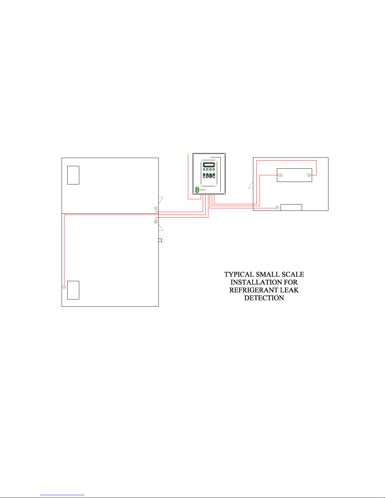
ZERO POINT
R
e
f
r
i
g
e
r
a
n
t
G
a
s
M
TQ 4200
o
n
i
ALARM 3ALARM 2ALARM 1
t
o
r
i
CONTROL
n
g
MENU
S
y
s
PANEL
t
e
m
COMPRESSOR
2 3
PLANT ROOM
1
GAUGE
PANEL
EVAPORATOR
COLD ROOM 1
COLD ROOM 2
TQ4200
TQ ENVIRONMENTAL PLC
Flanshaw Way, Wakefield, W Yorks England, WF2 9LP
Tel: + 44 (0)1924 380700 Fax: + 44 (0)1924 361700
Email: Sales@tqplc.com website :http://www.tqplc.com
4
5
ALARM
BEACON
6
EVAPORATOR
Sample lines.
For general installations 6mm OD, 4mm ID nylon tubing is sufficient and readily available.
When routing sample lines, be aware that short runs will facilitate faster response times. If
possible, sample lines should be run in one continuous length, as using pipe joining couplings
will cause flow restrictions. ( In practice the cost of a single length of tubing is often less than
the coupling. ) Avoid tight bends as this will kink nylon tubing causing blocked lines. Sharp
corners on framework etc can also cut the sample lines over time, especially on vibrating
machinery.
It is best to run pipework at head height or above where it is less likely to encounter
mechanical damage, such as being cut or crushed by machinery. Be careful not to cause a
hazard to personnel however by suspending pipework across open areas, from compressors
etc. Also avoid heat sources and hot pipework ( often found on compressors ) as this will melt
nylon tubing. If a more mechanically resistant tubing is called for, small bore copper tubing
can be used in these areas. Tubing should be clipped and tied to framework and walls at
Page 2 of 3
 Loading...