

TQC Sheen CP1 Operating Manual
ISSUE 1
C
ONE AND PLATE VISCOMETER
Operating Manual

1
Contents
Contents .................................................................................................................................................. 1
1 Safety Instructions ................................................................................................................................ 2
2 Packing information .............................................................................................................................. 3
3 Installation information ......................................................................................................................... 4
4 Introduction .......................................................................................................................................... 5
5 Instrument Operation ........................................................................................................................... 8
6 Instrument Control .............................................................................................................................. 1 0
7 Obtaining good results ....................................................................................................................... 35
8 Maintenance, cleaning and condition ................................................................................................. 38
9 Specification ....................................................................................................................................... 40
10 Operational accessories................................................................................................................... 42

2
1
Safety Instructions
1. Read this operating manual carefully before using the machine.
2. Retain this operating manual for future reference.
3. Observe all safety and warning markings on the machine.
4. Always position the unit on a solid, level surface.
5. This machine must only be used in areas electrically classified as NON-
HAZARDOUS.
6. Ensure the voltage setting matches your local power supply.
7. The power supply to the instruments IEC inlet socket must be connected to a
supply with earth, using the IEC power cord supplied.
8. Safety critical components:
a. This machine must be fitted with fuses as specified in this manual and as
appropriate to the supplied voltage.
b. Any replacement Mains Lead must have an equivalent specification to the
one supplied.
9. When operating the machine, remove any loose clothing or jewellery that could
become entangled and beware of moving parts.
10. Use normal handling methods taking care when unpacking and lifting the
instrument.
11. Do not use excessive amounts of paint or ink, the build-up of which may create a
fire hazard.
12. In order to avoid a fire hazard do not use flammable solvents when cleaning the
instrument unless absolutely necessary and in any case do not use on front panel
or labels.
13. Avoid solvent fumes when cleaning or using the instrument.
Do not dispose of this product with household, commercial or industrial
waste. Please refer to local disposal methods or contact us regarding the
proper handling of end-of-life electrical and electronic equipment.
Protection is impaired if used in a manner not specified by the
manufacturer.

3
2 Packing information
The instrument is supplied with smaller items separately packed. Carefully open the
top of the packaging before removing the instrument.
1. Identify all the items on the packing list. A copy of the packing list is provided
below for reference. Remove the separate items on top. The instrument is
protected by a plastic bag that includes desiccant sachets.
2. Remove the top of the packaging and then remove the instrument from the
packing case using both hands to lift the base and place securely on the bench
before removing the plastic cover. Safely dispose of the desiccant sachets.
3. Refer to the installation instructions.
Packing list
The following items will be included:
Viscometer
Mains power cable
Operating handle
10 protective front covers
User manual

4
3 Installation information
Please read all the relevant information before attempting installation.
Ensure the instrument is situated on a firm, hard, level surface, strong enough to
support its weight without significant vibration and in a well-ventilated area with
adequate access to the front and sides. The bench height must allow easy access to
the instrument and controls. Keep the left and right ventilation openings in the base
free from obstruction.
Remove the operating handle from its separate packaging and screw firmly into the
operating lever on the right-hand side.
The instrument uses a universal input voltage power supply.
Use the IEC lead provided to connect to the mains supply. If in doubt, consult a
qualified electrician.
The power inlet connector is located on the rear of the instrument’s base. The power
inlet houses the mains input fuse(s) and mains power switch. Check that the mains
switch is off and disconnect the mains plug before connecting the mains lead. Connect
the mains plug and then switch the instrument on. The display will light and the
instrument will go through a self-test procedure. Allow at least 30 minutes standing-
time before use the first time the instrument is switched on (or longer if cold).
5
4 Introduction
The Cone and Plate Viscometer was originally designed and developed to measure
the dynamic viscosity of paints that are non-Newtonian in behaviour. These types of
materials exhibit different viscosities depending on the shear rate applied to them.
Application of paints by brush, roller or spray gun, etc. generate shear which also
changes viscosity.
Variation in shear rates from 3000 s-1 to 15000 s-1 can be expected from normal brush
application of paints. A single figure of 10000 s-1 (BS) or 12000 s-1 (ASTM) is
considered a satisfactory compromise in simulating the effects of brush, roller and
spray applications of paints. The cone and plate viscometer was developed in order
to reproduce this effect in the laboratory.
The viscosity of other non-Newtonian liquids may be measured on this type of
instrument providing careful consideration is given to the shear-rate.
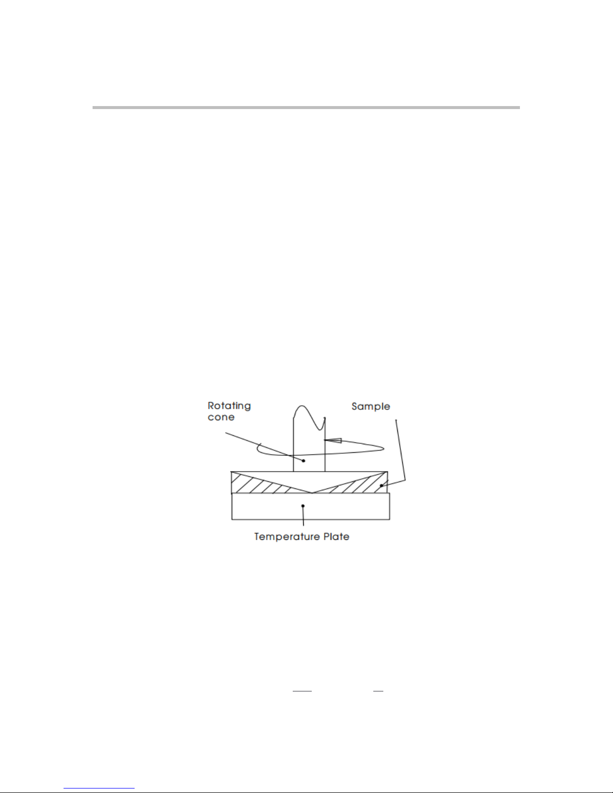
The shear rate (units of s-1) in the liquid under test is dictated by the cone angle (θ,
units of degrees) and the rotational speed of the cone, ω (units of radians.seconds-1)
according to the formula: 𝑠ℎ𝑒𝑎𝑟 𝑟𝑎𝑡𝑒 =
𝑤ℎ𝑒𝑟𝑒 𝜔 =
𝑥 𝑟𝑝𝑚

6
A rotational speed of 750 rpm has been chosen and is specified in BS3900 part A7
2000 (and ISO 2884-1 1999). This speed has proven to give accurate results without
generating unwanted heat during the test.
Using this formula, the cone angle required to give a shear rate of 10000 s-1 at 750
rpm is 0.45° (27’). Paint viscosity measurements are very sensitive to temperature
variations and so all tests are conducted under carefully controlled conditions:
achieved by providing a temperature controlled plate on which the cone rotates. The
test sample is applied to the plate and the cone is lowered onto the plate. Any excess
liquid between the plate and the cone is expelled. Both the sample and the cone are
kept within the close temperature limits set by the temperature controller in the
instrument - time is allowed for thermal equilibrium before the test is started.
The cone is set rotating and the torque (which is directly proportional to viscosity)
generated by the motor is measured and displayed.
Note that BS and ASTM standards quote different shear rates in their test methods –
10000 s-1 for BS3900: part A7: 2000 (and ISO 2884-1 1999), and
12000 s-1 for ASTM D4287-00
The original cone and plate viscometer (on which these test methods are based)
employed a synchronous motor to rotate the cone. With a 50Hz mains electricity
supply, the cone will rotate at 750 rpm. Using the same instrument on a 60Hz supply,
will cause the motor to rotate at 900 rpm. The CP1 meets both these standards since
the speed can be set to either 750 rpm or 900 rpm (independent of mains frequency).
Setting the instrument parameters
The instrument is quite flexible – many of the operating parameters can be set. It is
advisable to set the instrument parameters and then enable one of the two security
modes - doing this will prevent inadvertent changes.
Viscosity is displayed in centiPoise (cP), Poise (P), milliPascal seconds (mPa.s) or
Pascal seconds (Pa.s); the SI unit is Pa.s (or mPa.s). The relationship between these
units is –
0.1 𝑃𝑎. 𝑠 = 1 𝑃 = 100𝑐𝑃 = 100𝑚𝑃𝑎. 𝑠

7
The display units may be selected on the instrument, together with the display
resolution. A time of 15 seconds is a good value for both preheat and run times for the
CP1. Allow at least 30 seconds (with a hot cone) for the sample to stabilise at the
higher temperatures; shorter times may be used at the low end of the temperature
range. Once you are familiar with instrument operation, decide on whether manual
operation or automatic operation is best suited to your needs.

8
5 Instrument Operation
Using the cone for your viscosity range, turn the instrument on and allow the plate to
reach the set temperature. After a short time the instrument will display
** Ready **
Ensure that the cone value is correctly set (see top right of LCD).
The instrument is then available for use with the default settings supplied.
Taking a measurement
Ensure the cone and plate are clean.
Place a small amount of material to be tested on the plate (see later for
recommended sample volumes).
Lower the cone GENTLY and fully onto the plate – any excess material will flow
out from the side of the cone. The time taken for the cone and sample to reach
the plate temperature will depend on the sample and ambient temperature. At
least 15 seconds should be allowed and longer if the sample temperature is
significantly different (this can be timed automatically).
Press the start switch.
Allow the instrument to run for the pre-set run time. The result is displayed on
the screen until the next run is started.
Record the result as required.
Raise the head and clean the cone and plate.
Lower the plate onto the cone to keep it at the plate temperature before the
next test.

9
Changing and inserting cones
Fit a CP1 cone to the instrument as shown below –
Overload Error
The instrument measures the torque applied to the rotating cone and automatically
halts (displaying an overload error) if the torque value exceeds the maximum allowed.

10
6 Instrument Control
The following sections describe the instrument controls and menu operation.
Operating handle
The handle moves the cone up and down. A sensor detects when the cone is lowered
onto the plate. Operation may be set to manual or automatic (handle operated).
Mains power socket
A detachable power lead is provided. Only use this lead to connect to the instrument.
A plug must be used to connect the instrument to the mains supply. The mains supply
must be earthed.
Power indication
The rocker switch on the mains inlet is used to switch the mains power on and off. The
switch must be ON (indicated by the ‘1’ position) before the instrument can be
operated. The backlight on the display will operate when power is applied.
Controls
The control panel is located at the front of the instrument. It contains a LCD display, 5
keys and a LED.
The three keys to the right of the LCD display are used to set instrument conditions.
These are ‘soft-keys’ since they perform the function displayed to the left of them on
the LCD display. The bottom (of the three) keys is also used to start (and stop the
instrument) and to spin the cone for cleaning after a run - this operation will be
described later. The two keys below the display are used to increase or decrease a
set value once a menu option has been selected.
The operating handle is used to lower and raise the cone. The handle operates a
sensor when the cone is close to or touching the plate. The instrument may be set to
use the handle to lower the head (with a manual start) or to operate automatically.
It is possible to select auto-spin (after a measurement) to allow the cone to be cleaned
when the handle is raised. The various modes of operation will be described later.

11
Auxiliary Start/Stop switch
An additional start/stop (and spin) switch is located on the right-hand side of the base.
This switch performs the same function as the bottom right-hand display switch. These
switches may be used interchangeably to start and stop the instrument.
LED
The front panel also has a bi-colour LED that indicates the state of the instrument.
The instrument may be started any time the LED is green; the LED will flash when the
instrument is running. Operation is not possible when the LED is orange or red.
The LED is orange during periods when the instrument is on, but may not be used –
for example, after the temperature has just been changed or while a menu item is
selected. The LED is red during power-on diagnostics. The led will flash red when an
error condition is detected (such as motor overload).
LCD Display
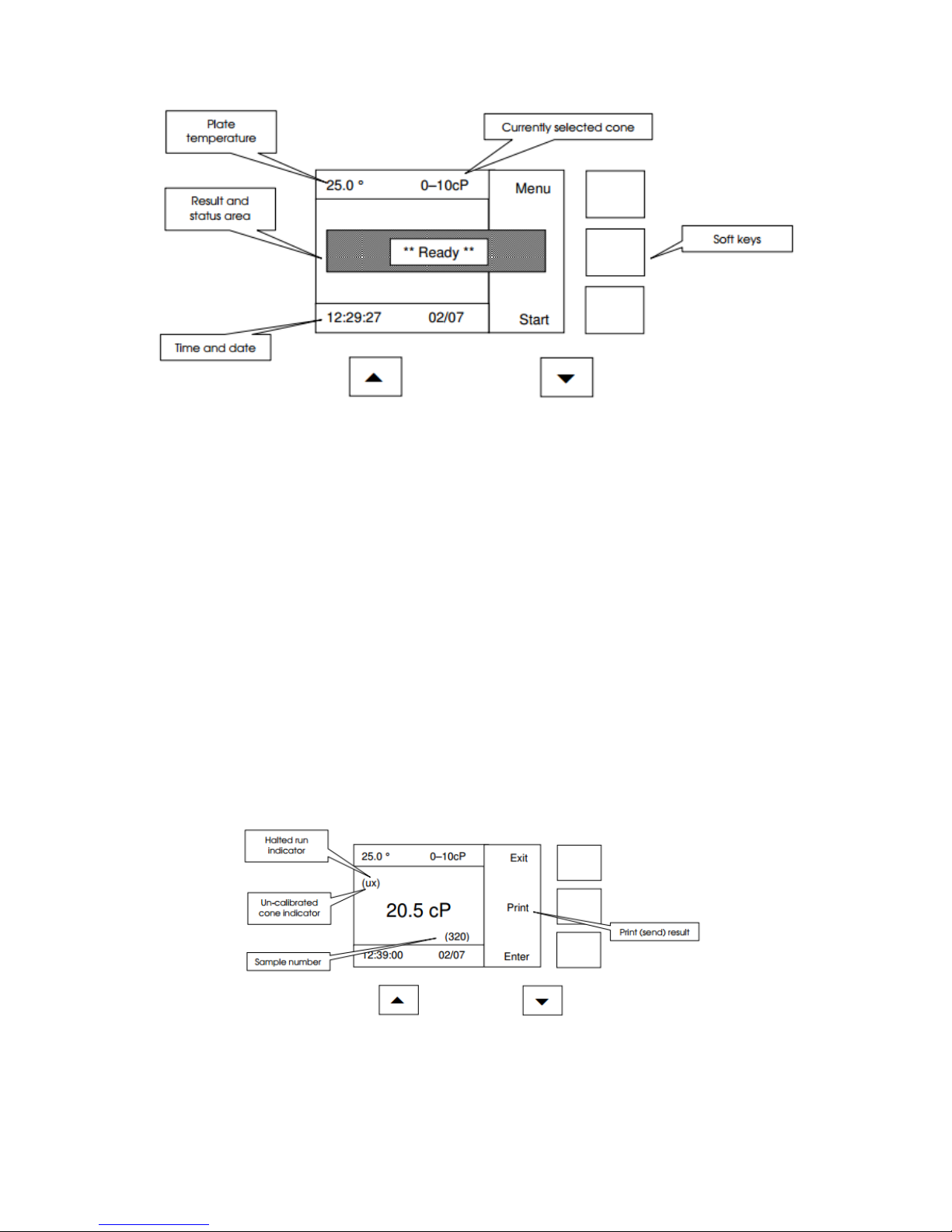
The LCD display indicates the current state of the instrument – see below (this
example shows the instrument is at temperature and ready to run).
The actual plate temperature (in °C) is shown at the top left of the LCD. The currently
selected cone is shown at the top right. The time and date are displayed on the bottom
line. The central shaded message box displays instrument readiness.
12
The text displayed next to the three right-hand switches varies from display to display;
pressing the switch next to the ‘soft-key’ will select the function displayed. Using the
example above, pressing the top right key will select the instrument menu and the
bottom right key will start the instrument.
Once a result has been recorded, the display will look similar to the one below. The
Sample id is shown in brackets underneath the result. The Sample id is automatically
incremented after each result. The x (top left of the result) will only be displayed if the
run was halted prematurely.
The LCD display backlight will dim after 10 minutes when the instrument is not being
used. Press any key to restore the backlight.
13
The Print key becomes visible once a result has been taken (manual mode only). Print
(after result) is always enabled when the instrument is in automatic mode. Results are
always printed in cP (mPas).
Protective front covers slot into the holder on the front of the head. Use these to
prevent contamination of the display; replacement covers are available.
Operation
After the instrument is switched on, the software version number is immediately
displayed, followed by the instrument type. The instrument then performs a power-on
check. Several internal checks are made on memory, the supply voltages and the
clock-battery; the results are displayed.
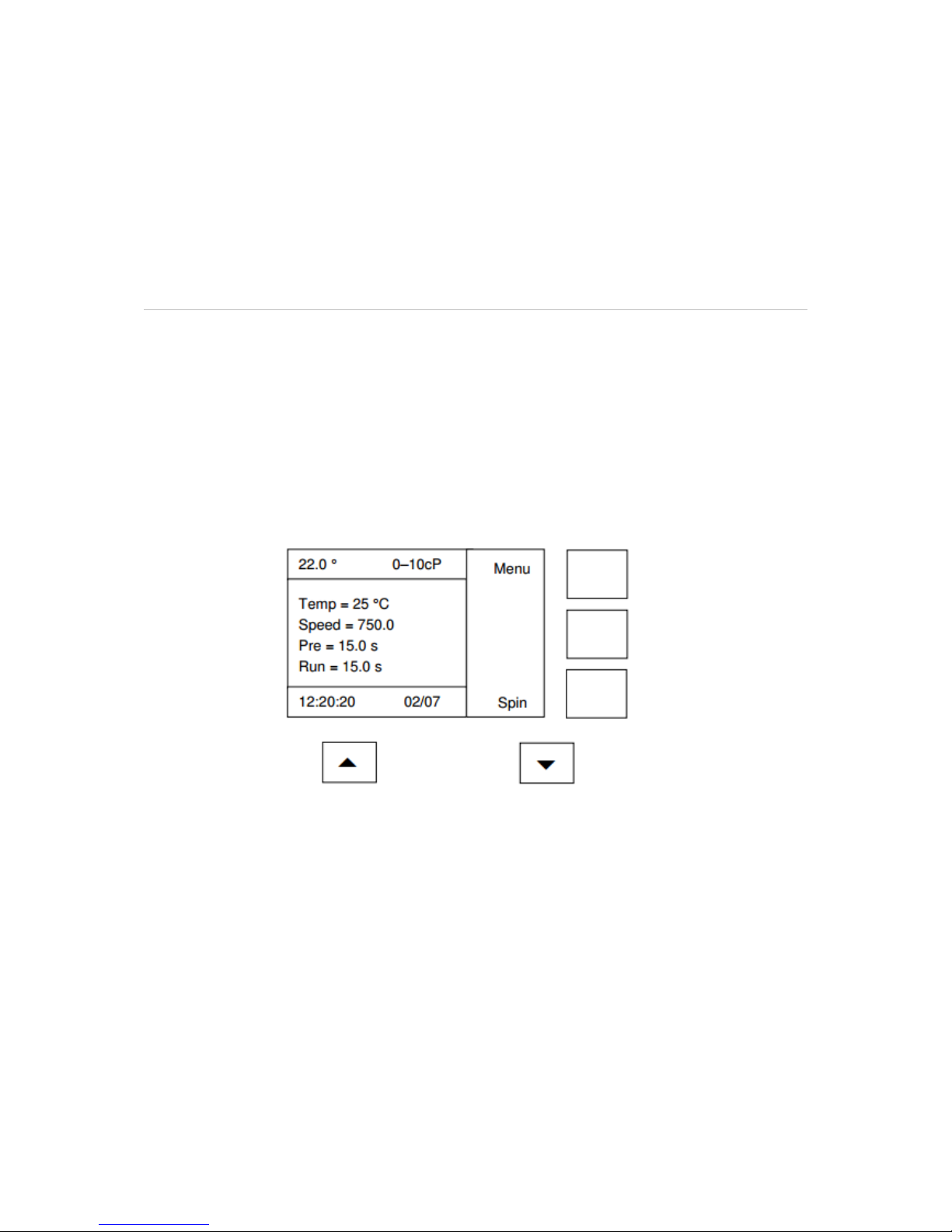
The instrument then displays a status screen (similar to the one below). This screen
shows the current settings for the instrument.
The display will change to one similar to the one shown below a few seconds later.
The temperature (top left of the LCD) will flash on and off until the plate reaches the
set temperature within its ready band (default ±0.1 °C). The instrument will be usable
once the temperature has fallen within the ready band.
 Loading...