

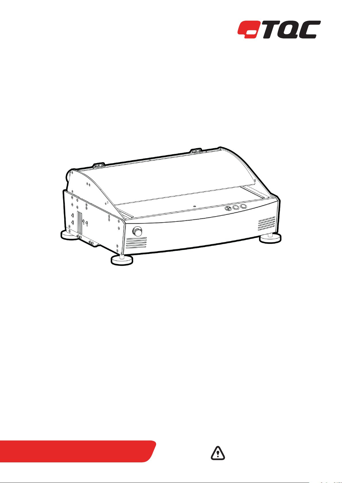
TQC CureView
Gradient Oven
AB8000 REV02
Gradient oven with GOC and
Ideal Finish control
Operating Instructions
(V1.2 0918)
IMPORTANT! Before taking this instrument
in use we strongly advise you to read this
manual carefully.


INDEX
1. General
1.1 Importance of operating manual
1.2 User-responsibility
1.3 Responsibility of personnel
1.4 Dangers
1.5 Designated purpose
1.6 Copyright
1.7 Manufacturer’s/Supplier’s address
2 Safety Instructions
2.1 Meaning of Symbols
2.2 Availability of Safety Information
2.3 Training of Personnel
2.4 Dangers from Electrical Energy
2.5 Points of Special Danger
2.6 Care, Maintenance, Repairs
2.7 Modifications to the Equipment
2.8 Cleaning of the Instrument and Disposal
of Materials
3 Transport and Storage
3.1 Packing
3.2 User: Check on Receipt
3.3 Reporting Transport Damage and
Documentation
3.4 Storage and Protective
Measures when not in use
4 Instrument Data
4.1 Name / Article
4.2 Scope of Supply
4.3 Technical Data
4.4 Dimensions and Weight
4.5 Basic Unit
4.6 Accuracy
4.7 Noise Level
4.8 Accessories and Spares
5 Installation and Assembly
5.1 Installation and Operation
5.2 Preparation of Energy Connections
5.3 Mains Connection
10 Installation Criteria
4 14
10.1 Climate
10.2 Power Supply
10.3 Worktable
10.4 Exhaust System
10.5 Installation Procedure
11 Thermal Dynamics
11.1 General
11.2 Basics of Gradient Ovens
5
11.3 Substrate Material
11.4 Surrounding / Environmental Conditions
11.5 Ramping
12 TQC Gradien Oven Control Software
12.1 Introduction
12.2 Prerequisite
12.3 Program Configuration
12.4 Modes and Stages
12.5 Configure a test in Setup Mode
12.5.1 General Setup
6
12.5.2 Pre-cooling Setup
12.5.3 Heating Setup
12.6 Execute a test in Run Mode
12.7 Initialization
12.8 Place Panel
12.9 Pre-cooling Oven
12.10 Heating
7/8
12.11 Lift Panel
13 Maintenance
13.1 Heater Replacement
13.2 Controller Replacement
10 Disclaimer
Annex A Operator Qualication List
9
Annex B Maintenance List
15
16/20
21/26
27
29/30
31
6 Instrument Controls and Functions
7 Instrument Preparations
7.1 Test Panels
7.2 Calibration Interval
7.3 Lamp Maintenance
7.4 Software
8 Operation
8.1 Preparatory Work
8.2 Sample Preparation
8.3 Start the Instrument
9 Care and Maintenance
9.1 Inspection and Maintenance
9.2 Disposal of Materials
9.3 Customer Service
10
11
12
13
3 |

1 GENERAL
This TQC CureView Manual is created in multiple parts. This to give the
operator the best experience with the TQC CureView. It is
essential that the full manual is read and understood prior to
commencing operation of the TQC CureView.
1.1 Importance of operating manual
This manual is written in order to become familiar with all the functions and
possible applications of the instrument. It contains important instructions
about how to use the instrument safely and economically; according to
the purpose designated. Following these instructions is not only essential
to avoid risks. It also reduces repair costs and down-time and increases the
products reliability and service-life.
Anyone who works with the instrument shall follow the instructions in this
manual, particularly the safety related instructions. Additionally local rules
and regulations relating to environmental safety and accident prevention
should be observed. It is mandatory that users have read and understand
this manual prior to first operation of the TQC CureView.
1.2 User-responsibility
The user should
a) Only allow persons to work with the instrument who are
familiar with the general instructions on how to work safely and
to prevent accidents. The use of the instrument should have been
instructed duly. The safety chapter and the warnings in this
manual should have been read and understood; acknowledged
as evidenced by their signature.
The TQC CureView Gradient oven is exclusively designed to perform
thermal testing to within its thermal design envelope of painted and
coated test panels as described within the specifications. Other applications
constitute improper use. TQC will not be held liable for damage resulting
from improper use.
Designated purpose also includes properly observing all instructions in the
operation manual, and adherence to inspection and maintenance
schedules. TQC is entitled to request these form when warranty claims are
made and during inspections to ensure safe operation and evaluate correct
usage.
1.6 Copyright
The copyright of this operating manual remains with TQC. This operating
manual is intended solely for the user and his personnel. Its instructions
and guidelines may not be duplicated, circulated or otherwise passed on to
others, neither fully, nor partly. Infringement of these restrictions may lead
to legal action may be taken if this restrictions are infringed upon.
1.7 Manufacturer’s/Supplier’s address
TQC – Molenbaan 19
2908 LL Capelle aan den IJssel
The Netherlands
T +31(0)10 7900 100
F +31 (0)10 7900 129
b) Regularly check the safety-awareness of personnel at work.
c) Only allow user maintenance on the instrument such as lamp
replacement and thermal board replacement / exchange only to
be performed by TQC qualified or appointed personnel.
Maintenance by unqualified personnel can result in serious
damage to the instrument and will not be accepted as claimable
warranty.
1.3 Responsibility of personnel
Before commencing work anyone appointed to work with the instrument
should pay attention to the general regulations relating to working safety
and accident prevention. The safety chapter and the warnings in this manual
should have been read and understood; acknowledged as evidenced by
their signature, as can be placed in the Operator qualification list Annex A.
1.4 Dangers
This instrument has been designed and constructed in accordance with
state-of-the-art technology and the acknowledged safety regulations.
Nevertheless, working with the instrument may cause danger to the life and
health of the operator or to others, or damage to the instrument or other
property. Therefore the instrument should only be used for its designated
purpose, and in a perfect technical condition. Any defect that could
have a negative effect on safety should be repaired and recorded in the
maintenance list Annex B immediately.
1.5 Designated purpose
| 4
2 SAFETY INSTRUCTIONS
2.1 Meaning of Symbols
The following symbols for dangers are used in this instruction manual.
Possible immediate
danger to the life or
health of personnel.
A dangerous situation
could be caused.
Special tips and
particular information.
2.2 Availability of Safety Information
The instruction manual should be kept in proximity to where the instrument
operates and should be visible and accessible at any time of operation.
In addition to the information contained in the instruction manual, general
and local regulations for accident prevention and environmental protection
shall be kept available and observed. Always ensure all guidelines in respect
of safety and dangers on the instrument are in readable condition.
In case of danger the instrument has to be switched off by means of the
emergency-button on the front of the instrument, then the danger should
be eliminated.
2.3 Training of Personnel
• Anyone who operates the instrument should be trained properly.
• It has to be clear who has which responsibility regarding commissioning,
set-up of maintenance and repairs, installation, and operation.
• Anyone who hasn’t finished training should be supervised by an
experienced person while working with the instrument.
If this guideline is not noted
it can lead to severe danger
to health, up to fatal injury.
Non observance of this
guideline can lead to injury
or to damage to equipment.
Guidelines to make optimal
use of the instrument.
2.6 Care, Maintenance, Repairs
• Always make sure the instrument is connected to an earthed socket.
• Maintenance and inspection should be carried out at the correct intervals
• Operating personnel should be informed before starting with
maintenance or repair work
• Always make sure the instruments power is turned off and the instrument
is not connected to a socket while adjusting any electrical component
whenever maintenance, inspection or repair work is done.
• Do not open the instrument. In case of malfunction always consult the
manufacturer.
2.7 Modications to the Equipment
• Any modifications or additions or alterations to the instrument may solely
be made with permission from the manufacturer.
• All measures involving modifications require written confirmation of
approval from TQC
• Instruments which are not in fault-free condition must immediately be
switched off
• Only use replacement parts from the original supplier. Parts used from
other sources aren’t guaranteed to take the loading and meet the safety
requirements.
2.8 Cleaning of the Instrument and Disposal of Materials
• When in use it is not always possible to avoid some spill of
paint on the work surface.
• Try to keep the instrument as clean as possible to prevent
distortions of functions.
• To clean the instrument properly use a suitable solvent to dispose
remains of paint or ink.
• Wear gloves during cleaning; Don’t spill an overdose of
solvent during cleaning.
• Cleaning materials must always be used and disposed of correctly.
2.4 Dangers from Electrical Energy
• Work on the electrical supply may only be done by a qualified electrician.
• The electrical equipment of the instrument must be checked regularly.
Loose connections and cable damaged by heat must be corrected
immediately.
• If any work is to be done on parts connected to a voltage supply, a second
person must be present to switch off the main switch if necessary.
2.5 Points of Special Danger
There is one special point of danger in the moving zone of the tool carrier:
Always be aware that the machine, components and test
panel can be hot and cause physical injuries by burning.
Keep your hands away from the heated area after the
instrument has started!
5 |

3 TRANSPORT AND STORAGE
3.1 Packing
• Please take note of pictorial symbols on the packing.
• Check for transport damages. If the packaging is damaged only accept it
with a written approval of the transporter that the package was damaged.
3.2 User: Check on Receipt
• Check packing for damage
• After unpacking check complete supply.
3.3 Reporting Transport Damage and Documentation
• Any damage should be documented as accurately as possible (possibly
photographed) and reported to the relevant insurers or, in the case of sales
“delivered to customers works”, to the supplier.
3.4 Storage and Protective Measures when not in use
• The instrument must be stored in a dry place at a temperature
between 10 - 40˚C / 50 - 104˚F.
• The storage period should not be longer than 3 months. When stored
longer than 3 months please contact the manufacturer for instructions on
recommissioning.
• Store instrument in the original packing if possible.
| 6
4 INSTRUMENT DATA
4.1 Name / Article
TQC CureView – Computer controlled thermal test center.
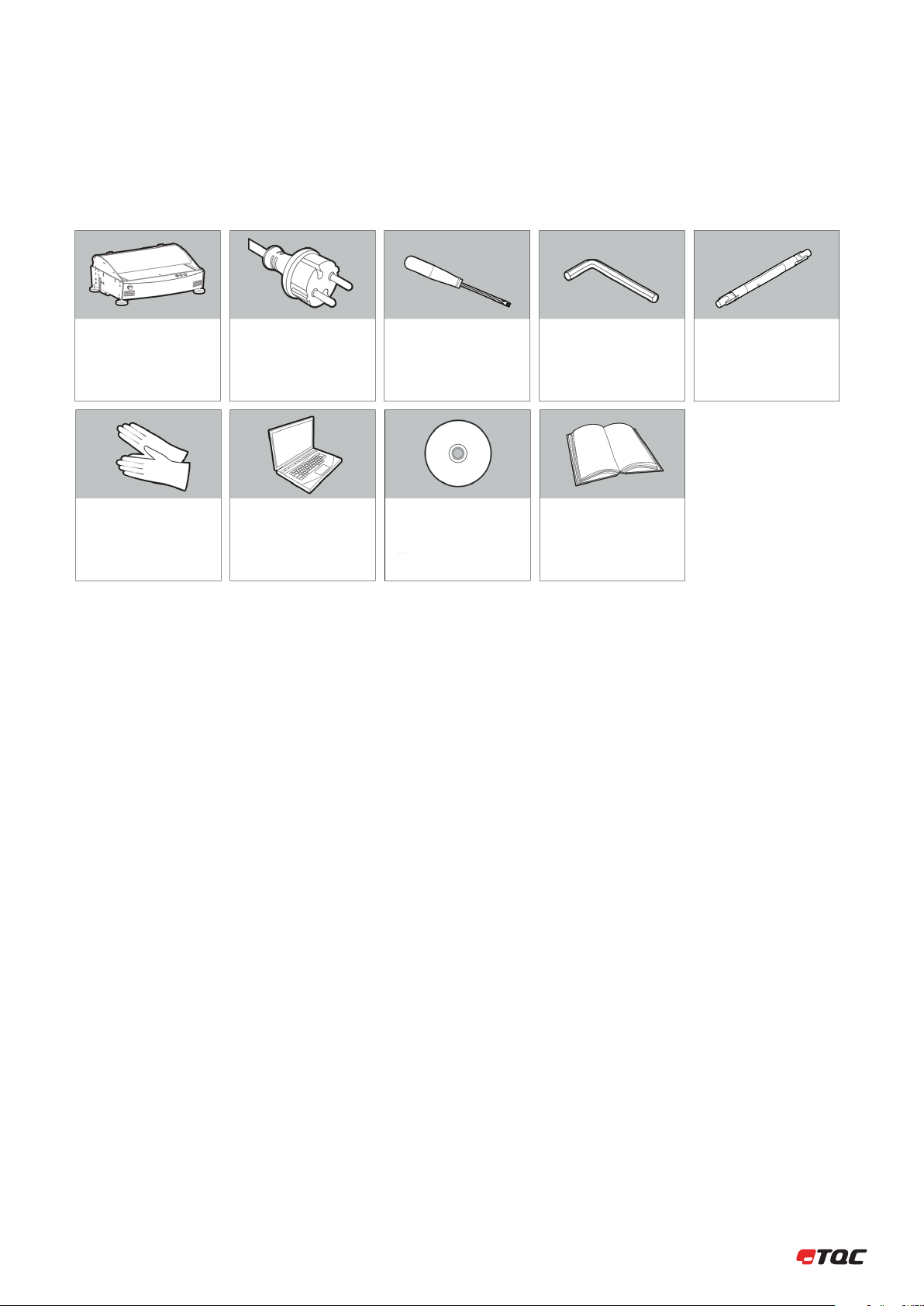
4.2 Scope of Supply
TQC CureView
Lamp Replacement
Gloves
Power Cord
Pre-installed Laptop
+ Laptop Power Cord
+ Laptop Installation
and documentation set
Lamp Replacement Tool
(Art. nr. AB8020)
TQC GOC and
TQC Ideal Finish
Software
Allen Key 2.5 mm
Allen Key 3 mm
Allen Key 4 mm
TQC CureView Manual
3x Spare Lamps
4.3 Technical Data
Temperature range: Ambient +5˚C to 350˚C
Maximum temperature difference: 50˚C / 122˚F (between 2 elements) (Thermal properties of test panel not included)
Number of heating elements: 32 elements, individually controlled.
Max. panel width: 98 mm / 3.86 inch
Max. panel length: Max 570 mm / 22.44 inch
Max. panel thickness: max. 1.0 mm / 0.03 inch
Effective test are: 500 x 74 mm / 19.69 x 2.91 inch
4.4 Dimensions and Weight
Depth: 595 mm / 23.43 inch
Width: 760 mm / 29.92 inch
Height: 296 mm / 11.65 inch
Net weight: approx. 31 kg / 68.34 inch
4.5 Basic Unit
Power Supply: 220 - 240 V, 50 - 60 Hz (single phase / split phase)
Power consumption: max. 3000 Watt
Display: None, status indication by 2 LED indicator buttons.
Safety: Emergency Button,
Function: 2 LED lit buttons, and computer control
4.6 Accuracy
Controller accuracy: 0.1˚C
Time control: 0.1 s/h
Heated accuracy: 3 ˚C
4.7 Noise Level
The continuous noise level from the instrument does not exceed 70 dB.
7 |

4.8 Accessories and Spares
Accessories
AB8025 CureView Gradient Oven Test Panels, set of 50 pcs
AB8026 CureView ISO 2812-5 Panel Adapter, suitable for Holding Panels size 500 mm x 100 mm
Spare parts
AB8016 Halogen Gold Reflector Infrared Heating Lamp (set of 10 pcs)
AB8020 Lamp Replacement Tool
AB8030 Nextrema Glass Test Surface
CM1105 USB Cable
AB8103 Power Supply Cable for CureView
| 8

5 INSTALLATION AND ASSEMBLY
5.1 Installation and Operation
The instrument has to be installed in a suitable place, preferably on a sturdy
table or work area, with normal ambient temperature. Special fixings are not
required. Exhaust for non-forced expel of fumes should be present. Carefully
unpack the apparatus and the accessories and check complete supply. Place,
if necessary, a spirit level on the work surface and adjust the height of the
feet. See also chapter 9.
5.2 Preparation of Energy Connections
The instrument is equipped with a safety tested mains supply cable and may
only be connected to plug sockets with earth connection complying with
the safety regulations.
Before connecting the instrument, check whether the supply
voltage corresponds to the local supply voltage. If it does
not, the instrument must not be connected under any
circumstances.
5.3 Mains Connection
The mains connection is located at the rear of the instrument. Plug in the
female plug in the socket on the rear of the housing. The ON/OFF Switch is
located at the right hand side near the end of the instrument.
9 |
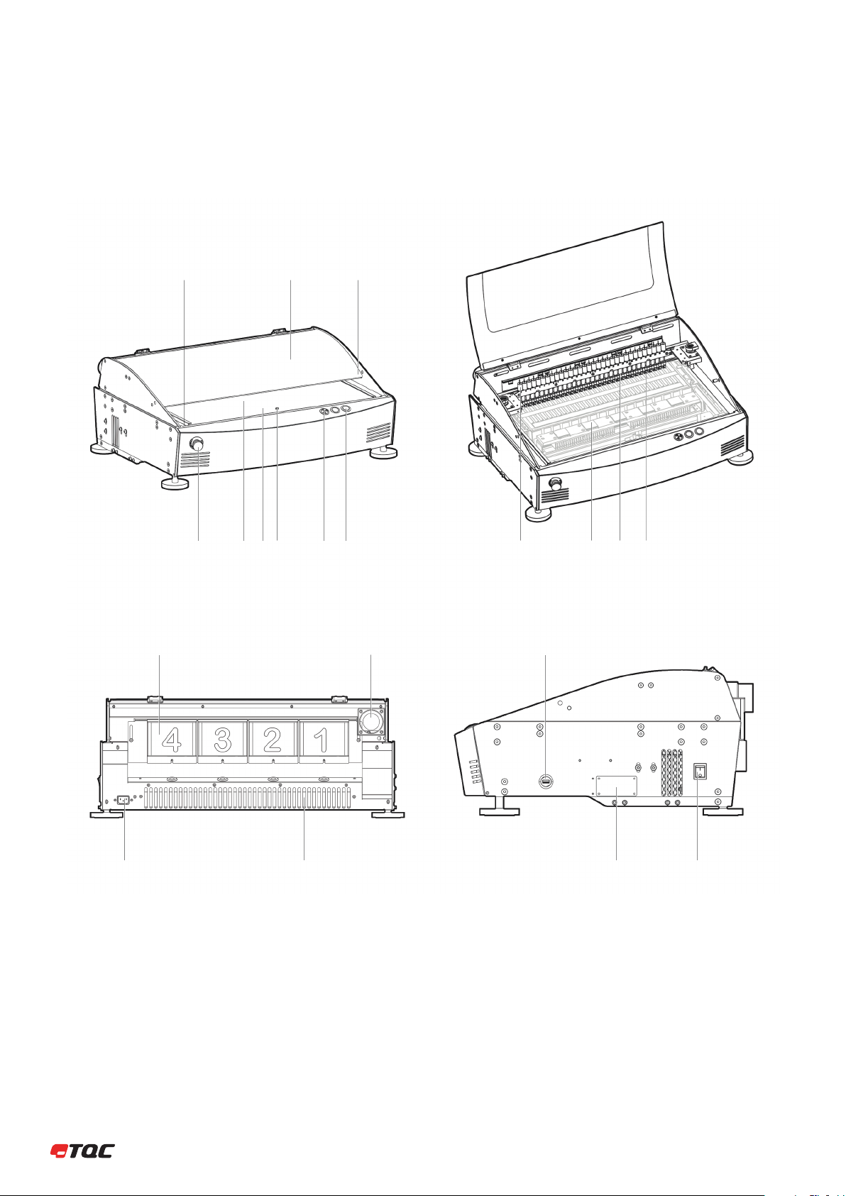
6 INSTRUMENT CONTROLS AND FUNCTIONS
1 2 3
4
14 15
5 6 7 8 9 10 11 12 13
1716
18
19 20
Panel Displacer
1
Protective Glass/Ceramic Cover
2
Canopy Safety Release
3
Emergency Stop
4
Test Surface
5
| 10
Loading Zone
6
Panel Lifter
7
Audio Alarm
8
Control Buttons
9
Thermal Sensors
10
11
Cooling Zone
12
Panel Clamp
13
Heating Zone
14
Controller Units
15
Fumex Exhaust
16
Power Supply Connection
17
Cooling Exhaust Machine
18
USB Connector
19
Identification Panel
20
Power Switch

7 INSTRUMENT PREPARATIONS
7.1 Start-up sequence
• Start the control computer or laptop.
• Once windows is launched start the TQC CureView.
• After 3 beeps the initiation of the TQC CureView in completed.
• Start the GOC software.
7.2 Test Panels
Prepare the panel as required by the test to performed. Make sure that no
wet/uncured paint or any other chemicals are applied at the area’s used by
the probes or pins. Only below depicted area can be used.
570 mm
x 12 mm
98 mm
x 35 mm x 35 mm
7.3 Calibration interval
The TQC CureView is supplied with 4 controllers each measuring and
controlling 8 channels. TQC advises to have an annual calibration interval.
Contact TQC or a local representative for information on how to calibrate the
TQC CureView.
7.4 Lamp maintenance
The carefully selected TQC Infra red heaters have a life expectancy of at least
5000 burn hours. In end this depends on the use of the lamps.
The replacement of the lamps should be performed as mentioned in the
chapter: “Replacing the Heater lamps” and should only be done by
authorized personnel.
7.5 Software
The TQC CureView operates in conjuction with Gradient Oven Control and
Ideal Finish software.
500 mm
74 mm
x 12 mm
11 |

8 OPERATION
8.1 Preparatory Work
• Turn the machine on as described earlier.
8.2 Sample preparation
Prepare a sample suitable for conducting the tests as required, and suitable
for the TQC CureView.
8.3 Start the instrument
Start the instrument following the steps listed in Section 12.
| 12

9 CARE
• Always clean the instrument after use.
• Clean the instrument using a soft dry cloth. Never clean the instrument
by any mechanical means such as a wire brush or abrasive paper. This may
cause, just like the use of aggressive cleaning agents, permanent damage.
• Do not use compressed air to clean the instrument.
Make sure that no paint or other liquids are spilled on the
electronics or left in the holes.
9.1 Disposal of Materials
Disposal of materials used in the operation of the instrument or for auxiliary
functions and exchanged items should be dealt with safety and in a manner
that will not harm the environment. Follow the local regulations.
9.2 Customer Service
Customer service is provided on request by
TQC – Molenbaan 19 , 2908LL Capelle aan den IJssel - The Netherlands,
T +31(0)10 7900100, F +31 (0)10 7900129 or by local representatives.
13 |

10 INSTALLATION CRITERIA
The TQC CureView is designed to operate in general lab conditions on a
sturdy worktable. In order to create the safest work environment possible
below requirements should met.
10.1 Climate
It is recommended to operate the TQC CureView in a temperature stable
environment. Due to the general tests performed with the TQC CureView a
climate controlled environment is advised having 20-25˚C / 68-77˚F and
40 – 60 %rH. Other ranges of temperature and humidity can limit the
minimal programmable temperature of the machine. For example if the
ambient temperature is 35˚C / 95˚F the minimal programmable temperature
is approximately 10˚C / 50˚F higher.
10.2 Power Supply
The TQC CureView is designed to operate at 220 - 240V / 50/60Hz power
supply, this due to the power consumption of 3500W. For the 230V /60Hz
equipped countries the 3500W is together with the laptop the maximum
power that can be drawn from a fuse. The CureView should be run on a
dedicated fuse. The TQC CureView cannot be connected to 110V power
supply. When the TQC CureView is intended for use in 110V countries the
CureView needs to be connected to Split phase power supply. Please
consort a suitable trained technician to verify the power supply.
There should be a second power plug available to
connect the laptop.
10.3 Worktable
A suitable and sturdy table needs to be selected with sufficient depth and
clearance above the table to operate the TQC CureView. No power supplies,
sockets or such may be placed behind the CureView that could block or
be affected by the heat exhaust in the rear of the CureView. The worktable
should be able to support 40 kg / 88.18 lbs of load and allow for placement
of the CureView with following clearances. The height of the table should be
selected such that ergonomic and safe operation is the machine is possible.
Please consult local guidelines and regulations.
10.4 Exhaust system
The CureView has a self-powered fume exhaust system mounted on the
rear. This system is created to allow fumes emanating from the test panel to
be expelled safely. The CureView may be connected to an already existing
ventilation system when this is a system without forced convection. If
the ventilation system has forced convention care should be taken not to
disturb the flow of air in the CureView.
10.5 Installation procedure
Verify that above criteria are met. If above criteria are met proceed as
followed:
Remove all packaging material from the CureView and store it
1
for possible later use.
2
Lift the CureView onto the the worktable by lifting it with 2
persons. Each grabing the machine from the side.
3
Connect the exhaust.
4
Connect the power supply.
5
Place the USB cable.
6
Install the supplied laptop.
7
Connect the USB cable to the laptop
8
Power up the TQC CureView.
> 600 mm
Exhaust
fumes
< 150 mm
9
Power up the laptop.
10
Verify that 2 beeps are sounded from the gradient oven.
11
Start the Gradient Oven Control software.
12
No error message should be shown.
| 14

11 THERMAL DYNAMICS
11.1 General
Even though the CureView is designed to the highest specifications possible
the CureView has limitations. We simply are not able to go beyond the laws
of physics. In order to explain some of the limitations of the TQC CureView
the following chapter will include some of the intricacies of thermal
dynamics involved with using the CureView.
11.2 Basics of Gradient Ovens:
The TQC CureView is a new generation of Gradient-ovens that allows for
significantly more advanced tests and doesn’t require preheating. The
implementation of the latest heating techniques in the TQC CureView
provide a different heat transfer compared to that of older systems with
conventional heating. The direct IR-irradiation by the TQC CureView allows
for a significantly more efficient heating than traditional gradient oven
systems. Due to this new heating system multiple components and
procedures had to be changed in the machine. Below is a simplified image
highlighting the difference in build of conventional systems and the new
TQC CureView.
Conventional heating IR-heating
Due to the difference in construction the heat transfer is significantly
different. Where the older systems work based on conduction of heat the
TQC CureView is based on transmittance of energy by IR-radiation. Older
Gradient ovens often suffer from loss in efficiency by improper contact
between the heating element, glass-bed and/or test panel. Because older
models have the thermocouple installed directly at the heater, they have
been compensated for the offset that occurs due to the different contacts
required to transfer the heat. Any small misalignment or other problem will
result in a loss of efficiency. This will cause significant differences in the
temperature of the test-panel. The TQC CureView is created such that it
regulates the heaters based on the temperature probe that is positioned on
top of the panel, thus at the actual spot where the temperature is relevant.
When comparing old and new systems side by side there might be a
temperature offset that has to be accounted for. This off-set is due to
deviation from older machines. Where test were set to be performed at
180˚C / 356˚F they could actually have been performed at 150˚C / 302˚F.
This off-set varies depending on the condition of the old machines.
To determine this off-set it is recommended to measure the actual
temperature obtained on the surface of the test panel.
Due to the new and improved heating systems no preheating is required.
This eliminates an irregular heating of the panel and allows for a repeatable
ramping of the temperature on the panel. The ramping is controlled and will
follow the same slope for all temperatures. The ramping for the heating can
be programmed in the Gradient oven. Below graph shows a default slope
being equal for all set point temperatures.
All following examples of ramping and heating graphs are
generalized and not correlated to a specic substrate or
ramp speed unless otherwise stated.
11.3 Substrate material
The main influence for differences between tests is the substrate that tests
are performed on. Different substrates react differently to heat. Some
substrate function as an isolator and others as an excellent conductor of
heat. This ability or it’s lack to conduct heat determine the maximal
temperature difference between 2 heaters. On a well conducting material
the difference between 2 elements is lower than on a less conducting
substrate. The property of metals to conduct heat is a temperature
dependent function. If a gradient from 25˚C to 125˚C / 77˚F to 257˚F
is obtainable this doesn’t mean that 125°C to 225°C / 257˚F to 437˚F is
possible as well or vice versa. In order to test for the suitability of a program
and/or substrate it is advised to run a test-run on uncoated substrate prior
to performing the real test.
Full thermal properties of a substrate can be calculated. Full calculations
and factors can be found in the “ Handbook of Chemistry and physics.”
Calculating the thermal response of panels is however tricky due to the
large number of variables.
11.4 Surrounding / environmental conditions.
The TQC CureView has been designed such that it will keep draft away
from the panel but still allow the panel to be visible. Though the Cureview
is designed to eliminate as many influences as possible. Small fluctuations
in the heating behavior can be caused by changes in temperature and
humidity of the surrounding air. These parameters not only influence
the heating capabilities of the CureView but in more significant manner
the evaporation of samples as tested according the ISO 2812-5 or curing
of powder coatings. Stable laboratory conditions are required to create
reproducible results. Please consult internal guidelines or international
standards for the required climatic conditions required for the performed
test.
11.5 Ramping
The TQC CureView can be set for custom ramping speeds. A Ramping
indicates the speed in degree per second the CureView will heat a panel.
The selected ramping will influence the amount of heat generated by the
lamps. The generated heat needs to flow from the bottom of the panel to
the top prior to being detected by the probes. This process depends on
the thermal properties of the test panel. Thickness, material type, surface
finishing and set end temperature all influence the thermal response. If the
ramping is set to high there might be an overshoot of the set temperature.
In the following graph the vertical axis shows the temperature in ˚C and the
horizontal axis displays the time (s). All set temperatures follow the same
ramp. Adjusting the ramp value can control the ramp slope.
15 |

12 CONTROL SOFTWARE MANUAL
12.1 Introduction
This document describes the TQC Gradient Oven Control Software (GOC)
version 1.11, which allows you to setup and run elevated temperature tests
in the Gradient Oven. The GOC is driving the instruments actuators, heaters
and sensors. The GOC works in conjunction with the TQC Ideal Finish analysis
software (IFA), which receives and displays the temperature profile data from
the GOC.
12.2 Prerequisite
In order to view and analyze temperature profiles the TQC Ideal Finish
Analysis Software version 6.0 or higher has to be present on the same
computer.
12. 3 Program conguration
Before starting a test it is good practice to configure two settings of the GOC
located in the tools menu.
Setup mode
Run mode
Tools -> Option
GOC File Locations:
Specify where the GOC configuration files shall be saved to a storage device,
file extension *.goc.
The configuration file describes various test parameters that are used during
a test, for example panel name, duration and temperature parameters of the
test. All these parameters are configured in the software setup mode.
Default temperature Units:
Specify in which temperature units the GOC shall display its values by
default.
12.4 Modes and stages
The Gradient Oven Control software has two modes a setup mode and a
run mode. The program starts up in the setup mode showing the setup
stage enumerator, which guides the user through the setup in four steps.
Once setup is completed and the run is started the program will switch to
run mode, showing the run stage enumerator with the thirteen stages from
begin to the end of the test.
12.5 Congure a test in setup mode
The setup stage enumerator shows the four stages that are configured
manually and which can be saved to a storage device for future use. The
basic commands New, Open and Save to handle configuration files are
grouped together in the menu bar and in the tool bar.
New:
Create a new test configuration.
Open:
Open a saved test configuration file.
Save:
Save a test configuration to file on a storage device.
| 16
Save As…:
Save a test configuration to file with another name on a storage device.

12.5.1 General setup
Use the general setup page to specify a name for the panel under test. In IFA
the name of panel will be used as identification for the temperature profile.
Use Temperature units to override the default setting in this configuration
only.
Start run:
Command to switch the program in run mode and skip any remaining steps
from the setup mode stage enumerator. Use this command to switch to run
mode instantly for example after opening a configuration file.
Cancel run:
Command to cancel the current run and switch to program to setup mode.
Use the red button on the front of the gradient oven to obtain the same
result.
12.5.2 Pre-cooling setup
The gradient oven cooling zone consists of five Peltier cooling elements
that can cool down the panel under test. The cooling zone is not
temperature controlled and only driven by a predefined power and
duration. Use the pre-cooling setup to configure the cooling power and
duration in the cooling zone that shall be applied to the panel under test
prior to the heating stage.
Power (%):
Defines the amount of cooling in percentage of the gradient oven cooling
system.
Duration (s):
Defines the amount of time in seconds that the cooling shall be applied.
Proceed:
Command to step to the next stage in the setup mode stage enumerator,
obtain the same result as selecting a stage by mouse. The command will
switch the program into run mode if the Pre-cooling stage was previously
selected. Use the green button on the front of the gradient oven to obtain
the same result.
17 |

12.5.3 Heating setup
The gradient oven heating zone consists of thirty two heating elements,
which are displayed in one record in the program. Each heating element
has its own temperature set point. The duration is set for all thirty two
heating elements at once. The individual heating settings allow applying a
temperature gradient over the length of the panel, whereas multiple records
allow applying a temperature gradient in time.
Use the column Set All to add an identical value to all heaters at once.
Add gradient:
Command to configure a temperature gradient from and to a specie
temperature, the control will automatically calculate all values between the
lowest and highest temperature setting.
Clone column to right:
Command to copy one heater to all other heaters to the right of the
selected heater.
Delete row:
Command to delete the selected row.
Import PFS:
Command to import IFA profiles, generated from GOC or from CurveX
measured temperature data.
Select PFS File:
Command to select the IFA temperature profile for import. After import the
Mapping tab shows the imported temperature profile for each probe on
the left and the gradient oven heaters to which these probes will link on the
right.
Add row after current selection:
By default a row is inserted before the selected row, check this option to
insert a row after the current selection.
Start at heater:
Specify the heater from which the gradient shall begin.
Begin temperature:
Specify the start temperature at the heater specified at Start at heater.
End at heater:
Specify the heater at which the gradient shall end.
End temperature:
Specify the stop temperature at the heater specified at End at heater.
Duration:
Specify the duration of this gradient heating cycle.
| 18
The link between probes and heaters can be changed by drag and drop a
heater onto the desired probe.
Use the white/red close window command to remove a heater from the
assigned probe, the heater will move to the Not allocated to a probe
section at the bottom of the window.
Click the Heater windows to rotate the heater order.
File Details:
Use the file tab to view the imported temperature probes in a graph.

12.6 Execute a test in run mode
In the Post-cooling setup the two commands start run and proceed will act
the same way and switch the program into run mode.
Start run:
Command to instantly switch the program into run mode and begin
execution of the configured panel test. Once in run mode this command is
disabled and the cancel run command is enabled, which allows cancel of the
test in any run mode enumerator stage.
Proceed:
Command to begin execute the configured panel test.
Fume fan:
Command to control the exhaust fume fan. Use this control to flow off fume
that may originate from the running test.
12.8 Place panel
The gradient oven carrier is waiting in the loading area allowing placement
of the panel into the carrier.
Once this stage is completed press Proceed.
12.9 Pre-cooling oven
In this stage the gradient oven clamp is lowered onto the heaters to
verify that the heating zone is cooler than the configured oven test panel
temperature. Each probe must measure an actual temperature that is
lower than the target temperature before the gradient oven transports the
panel any further. In case the system temperature is higher the gradient
oven internal fan will switch on at 100% until all probes are measuring a
temperature lower than the configured temperature.
Cancel run:
Command to cancel the current run and switch to program to setup mode.
Use the red button on the front of the gradient oven to obtain the same
result.
12.7 Initialization
In this stage the gradient oven will get ready for run mode. The run stage
enumerator shows the thirteen stages that a panel test follows. The stages
include loading the panel into the oven loading area, where after the panel
is transported to the cooling area followed by a transport to the heating area.
After the test the process is reverted and the panel returns to the loading
area.
Congure a target temperature that is at least higher than
ambient temperature in order to avoid the oven to wait for
a condition that can’t be met.
Transport panel
The panel is transported from loading to cooling area.
Cooling
The panel is cooled down according to the configured Pre-cooling setup.
Transport panel
The panel is transported from cooling to heating area.
Clamp panel
The panel is clamped onto the glass bed by the weight of the probes.
19 |

12.10 Heating
In this stage the gradient oven starts the heating cycle according to the
configured heating setup.
Measured temperatures:
The graph displays the measured temperature (blue) vs the configured set
temperatures.
Congured temperatures:
The graph display the set temperatures.
Unclamp panel
The heating stage is ended, the clamp is lifted and the probes are moved
upwards in order to free the panel for transport.
12.11 Lift Panel
The panel is ready and presented to the user for analysis.
Lift panel:
Command to lift or lower the panel in the loading area.
Return to conguration:
Command to switch from Run mode to Setup mode where the next run is
configured.
Transport panel
The panel is transported from heating to cooling area.
Cooling
The panel is cooled down according to the configured Post-cooling setup.
Transport panel
The panel is transported from cooling to loading area.
| 20

13 MAINTENANCE
The TQC CureView is created such that a minimum of maintenance is
required on an annual basis. Due to the temperature resistant materials used
for the production only a hand full of components need to be checked and
maintained. Maintenance of the TQC CureView should only be performed
by competent personnel.
21 |

13.1 HEATER REPLACEMENT
The TQC CureView uses IR heaters to heat the panel. These heaters have a limited life expectancy of
5000 burn hours. It is advised to replace the heaters on an annual basis. Older heaters can influence
the performance of the TQC CureView and limit the ramping capabilities of the TQC CureView, or
cause a significant loss in efficiency. Following procedure should be followed for replacing the
heaters.
1
Turn machine off by using the switch
button on the right side of the instrument.
2
Disconnect power supply and USB cable.
Frequency:
Annual replacement (adviced) or
individual lamp replacement
By:
Supervisor / TQC representative
3
Unscrew frontpanel allen keys
(2.5 mm) located one on each side to release
front cover.
4
Slide front cover down and tilt to front.
7 8 9
Remove the front pressure pin bar.
By unscrewing the allen key (3mm) on each
side and sliding it forward.
5
Loosen the 2 allen keys (3mm) that hold
the panel lifter in place, and lower the
panel lifter until it is below the glass bed.
Slide the glass bed forward. This might take a
little effort because the plate is still clapped
at some placed.
| 22
6
Open the glass top cover and loosen the
2 allen keys positioned on the rear corners
of the glass bed.
Gently lift the middle deflector and store it.

10 11
Gently remove the front deflector by
sliding it out upwards from between the
lamps.
Before proceeding always wear the
supplied cotton gloves to prevent
contamination from the hands to be
transferred to the lamps. Contamination
on the heaters will signicantly reduce the
lifetime expectancy.
Gently remove the back deflector by
sliding it out upwards from between the
lamps.
12 13 14
Place the special heater tool between the
heater and the socket, and lift the lamp
out of its socket. Lift the front side of the
heater with two hands. Pull it slightly
to the front to release it from the rear
socket and lower it out from under the rear
deflector.
The pin on the bottom of the heater
must be positioned correctly. For a more
uniform heat distribution these are
mounted alternating. On the uneven
positions on the back side and at the
even to the front.
Take the new heater from its protective
package and place it in the same way as
the original heater was positioned using
the heater placement tool.
Place the front deflector. Place the back deflector.
15 16
Align the placed heater such that it is
pointing upward. Assure all other lamps
are correctly aligned as well.
23 |

Place the middle deflector. Make sure the front of the glass bed in
17
Slide the glass bed gently back in place.
18
Make sure it properly aligns to slide it in the
last 1-2 cm.
19
inline with the aluminum housing.
20
Gently tighten the 2 rear allen keys that
hold the glass bed in place.
23 24 25
Replace the front cover and slide it
upwards to fix it in place.
21
Replace the front pressure pin bar, and fix
the 2 allen keys.
Fix frontpanel allen keys (2.5 mm) located
one on each side to release front cover.
22
Move the panel lifter back up. Make sure
it sits.
Connect power supply and USB cable.
Verify with a test run that all lamps are
functioning again.
| 24

13.2 CONTROLLER REPLACEMENT
The TQC CureView is equipped with 4 temperature control units. These units allow for simple repairs
and or placement of newly calibrated units. The calibration of these units is transferrable to the
Gradient oven the controller will be placed on. Though appearing universal the controllers need to be
placed at a specific location on the CureView. The locations are marked on the rear of the units. The
units control the following heaters:
Unit 1 Heaters / probes 1- 8 Unit 3 Heaters / probes 17 - 24
Unit 2 Heaters / probes 9 - 16 Unit 4 Heaters / probes 25 - 32
Turn machine off.
1
2
Disconnect power supply and USB cable.
Frequency:
Annual if required for calibration or
individual for defect probe replacement.
By:
Supervisor / TQC representative
3
Unscrew the 2 allen keys (3mm) holding
the rear cable cover in place.
Slide the cover downward and tilt it out.
4
Unscrew the nut (7mm) below the
7
controller.
5
Disconnect the BUS-connector cable from
the controller.
8
Repeat steps 5, 6 and 7 for all controllers
that need to be disconnected.
6
Disconnect the power and heater lead
cables from the controller.
9
Loosen the 2 allen keys (3mm) on each
side of the controller holder plate.
Allowing the plate with the controllers to
slide down.
25 |

Open the cover of the CureView. Push the spring behind the probe block
10
11 12
backward.
Push back the base of the probe block at
the notch and lift the probe block out.
13
Lift the controller and guide the probe
block out through the back of the
CureView.
16
Reconnect the connectors. Take care
the TQC-BUS connector(s) is/are placed
correctly.
Take care not to switch the controllers or
place them at the wrong locations. Do
not exert force on the cables connecting
the probe to the controller.
Raise the controller holder plate and
17
tighten the allen keys (3mm) on each
side.
1514
Fix the nut below the controller.Replace the controller with a new one.
18
Tilt and slide in the rear cable cover back
in place. Fix the 2 allen keys to hold it in
place.
If the cables prevent a smooth
positioning. Use the allen key to gently
push the cables down. To allow to slide
the cable cover back in place.
| 26

14 DISCLAIMER
The right of technical modifications is reserved.
The information given in this manual is not intended to be exhaustive and
any person using the product for any purpose other than that specifically
recommended in this manual without first obtaining written confirmation
from us as to the suitability of the product for the intended purpose does so
at his own risk. Whilst we endeavor to ensure that all advice we give about
the product (whether in this manual or otherwise) is correct we have no control over either the quality or condition of the product or the many factors
affecting the use and application of the product. Therefore, unless we specifically agree in writing to do so, we do not accept any liability whatsoever
or howsoever arising for the performance of the product or for any loss or
damage (other than death or personal injury resulting from our negligence)
arising out of the use of the product. The information contained in this manual is liable to modification from time to time in the light of experience and
our policy of continuous product development.
27 |


ANNEX A | OPERATOR QUALIFICATION LIST
Supervisor list (allowed to perform lamp replacement and such).
Date Name Signature SignatureInstructed by
29 |

Operator list.
Date Name Signature SignatureInstructed by
| 30

ANNEX B | MAINTENANCE LIST
Date Action Name Signature
Installed at test location.
First run performed.
31 |

TQC B.V.
Molenbaan 19
2908 LL, Capelle aan den IJssel
Nederland
+31 (0) 10 – 7900 100
+31 (0) 10 – 7900 129
info@tqc.eu
www.tqc.eu
TQC GmbH
Nikolaus-Otto-Strasse 2
Hilden, D-40721
Duitsland
+49 (0)2103-25326-0
+49 (0)2103-25326-29
info.de@tqc.eu
www.tqc.eu
TQC ITALIA s.r.l.
Via Cesare Cantu’ ,26
SEREGNO, (MB) 20831
Italië
+39 0362-1822230
+39 0362-1822234
info@tqcitaly.it
www.tqc.eu
TQC UK
Po Box 977A
Surbiton, KT1 9XL
Engeland
+44 208 255 0143
-
janet@tqc.eu
www.tqc.eu
TQC-USA Inc.
4053 S. Lapeer Road / Suite H
P.O. Box 108 Metamora, Michigan 48455
USA
+1 810-678-2400
+1 810-678-2422
joel@tqc-usa.com
www.tqc-usa.com
TQC Norge AS
Øvre Langgt. 26
Tønsberg, 3110
Noorwegen
+47 333 10220
+47 333 10221
info@tqc.no
www.tqc.no
 Loading...