

TQC AUTOMATIC FILM APPLICATOR (INCL. OPTIONAL DRYING TIME RECORDER)
AB3120, AB3220, AB3320, AB3400, AB3125, AB3225, AB3325, AB3405
IMPORTANT!
Before operating this instrument we strongly
advise you to read this manual carefully.
Operating Instructions for the
AUTOMATIC FILM APPLICATOR
MICROPROCESSOR CONTROLLED
V2.02-1213
Index
automatic-film-applicator-ab3120-m44 - Page 2 of 23
1 GENERAL ....................................................................................................................................................................................................... 4
1.1 Importance of operating manual ............................................................................................................................... 4
1.2 User-responsibility ........................................................................................................................................................... 4
1.3 Responsibility of personnel .......................................................................................................................................... 4
1.4 Dangers ................................................................................................................................................................................ 4
1.5 Designated purpose ........................................................................................................................................................ 4
1.6 Copyright ............................................................................................................................................................................. 4
1.7 Manufacturer's/Supplier's address ............................................................................................................................. 4
2 SAFETY INSTRUCTIONS ............................................................................................................................................................................ 5
2.1 Meaning of Symbols ........................................................................................................................................................ 5
2.2 Availability of Safety Information ............................................................................................................................... 5
2.3 Training of Personnel ...................................................................................................................................................... 5
2.4 Dangers from Electrical Energy ................................................................................................................................... 5
2.5 Points of Special Danger ................................................................................................................................................ 5
2.6 Care, Maintenance, Repairs ........................................................................................................................................... 6
2.7 Modifications to the Equipment ................................................................................................................................. 6
2.8 Cleaning of the Instrument and Disposal of Materials ........................................................................................ 6
3 TRANSPORT AND STORAGE ................................................................................................................................................................... 6
3.1 Packing ................................................................................................................................................................................. 6
3.2 User: Check on Receipt ................................................................................................................................................... 6
3.3 Reporting Transport Damage and Documentation ............................................................................................. 6
3.4 Storage and Protective Measures when not in use .............................................................................................. 6
2 |

automatic-film-applicator-ab3120-m44 - Page 3 of 23
4 INSTRUMENT DATA ................................................................................................................................................................................... 7
4.1 Name / Article .................................................................................................................................................................... 7
4.2 Scope of Supply ................................................................................................................................................................ 7
4.3 Technical Data ................................................................................................................................................................... 8
4.4 Dimensions and Weight ................................................................................................................................................. 8
4.5 Basic Unit ............................................................................................................................................................................. 8
4.6 Noise Level .......................................................................................................................................................................... 8
5 INSTALLATION AND ASSEMBLY ............................................................................................................................................................ 9
5.1 Installation and Operation ............................................................................................................................................. 9
5.2 Preparation of Energy Connections ........................................................................................................................... 9
5.3 Vacuum Connection ........................................................................................................................................................ 9
5.4 Mains Connection ............................................................................................................................................................ 9
6 INSTRUMENT CONTROLS AND FUNCTIONS .................................................................................................................................. 10
6.1 Overview ........................................................................................................................................................................... 10
7 INSTRUMENT COMPONENT ASSEMBLY .......................................................................................................................................... 11
7.1 Overview ........................................................................................................................................................................... 11
7.2 Instrument Preparations ............................................................................................................................................. 12
7.3 Plate Glass Panel ............................................................................................................................................................ 12
7.4 Vacuum Suction Plate .................................................................................................................................................. 12
7.5 Double Channel Vacuum ............................................................................................................................................ 12
7.6 Film Applicators (Tools) ............................................................................................................................................... 12
7.7 Test Charts ........................................................................................................................................................................ 13
7.8 Drying Time Recorder .................................................................................................................................................. 13
7.9 Multi Tool Platform ....................................................................................................................................................... 13
8 MENU DISPLAY INFORMATION AND OPERATION ....................................................................................................................... 14
8.1 Automatic Film applicator operation ..................................................................................................................... 14
8.2 Drying Time recorder operation .............................................................................................................................. 16
8.3 Heated Film bed control ............................................................................................................................................. 17
8.4 Warning signals .............................................................................................................................................................. 17
9 OPERATION ............................................................................................................................................................................................... 18
9.1 Preparatory Work ........................................................................................................................................................... 18
9.2 Film Application ............................................................................................................................................................. 18
9.3 Start the instrument ..................................................................................................................................................... 18
10 CARE AND MAINTENANCE ................................................................................................................................................................ 18
10.1 Inspection and Maintenance ................................................................................................................................ 18
10.2 Disposal of Materials ................................................................................................................................................ 18
10.3 Customer Service ...................................................................................................................................................... 18
11 DISCLAIMER ............................................................................................................................................................................................ 19
ANNEX A | INSTALLATION OF THE VACUUM BED ........................................................................................................................... 20
ANNEX B | POSITIONING OF SPIRAL BAR LIFTER .............................................................................................................................. 21
ANNEX C |INSTALLATION OF THE LAMP ............................................................................................................................................ 22
3 |

automatic-film-applicator-ab3120-m44 - Page 4 of 23
1 GENERAL
1.1 Importance of operating manual
This manual is written in order to become familiar with all the functions and possible applications of the
instrument. It contains important instructions about how to use the instrument safely and economically;
according to the purpose designated. Following these instructions is not only essential to avoid risks. It also
reduces repair costs and down-time and increases the products reliability and service-life.
Anyone who works with the instrument should follow the instructions in this manual, particularly the safety
related instructions. Additionally local rules and regulations relating to environmental safety and accident
prevention should be observed.
1.2 User-responsibility
The user should
a) Only allow persons to work with the instrument who are familiar with the general instructions on how to
work safely and to prevent accidents. The use of the instrument should have been instructed duly. The
safety chapter and the warnings in this manual should have been read and understood; acknowledged as
evidenced by their signature.
b) Regularly check the safety-awareness of personnel at work.
1.3 Responsibility of personnel
Before commencing work anyone appointed to work with the instrument should pay attention to the general
regulations relating to working safety and accident prevention. The safety chapter and the warnings in this
manual should have been read and understood; acknowledged as evidenced by their signature.
1.4 Dangers
This instrument has been designed and constructed in accordance with state-of-the-art technology and the
acknowledged safety regulations. Nevertheless, working with the instrument may cause danger to the life and
health of the operator or to others, or damage to the instrument or other property. Therefore the instrument
should only be used for its designated purpose, and in a perfect technical condition. Any defect that could have
a negative effect on safety should be repaired immediately.
1.5 Designated purpose
The TQC Film applicator is exclusively designed to apply films of paint and coatings on test panels and test
charts and as from models launched after Apr. 2013 for testing of the drying time of coatings on previous
described substrates.
Other applications constitute improper use. TQC will not be held liable for damage resulting from improper use.
Designated purpose also includes properly observing all instructions in the operation manual, and adherence to
inspection and maintenance schedules.
1.6 Copyright
The copyright of this operating manual remains with TQC.
This operating manual is intended solely for the user and his personnel. Its instructions and guidelines may not
be duplicated, circulated or otherwise passed on to others, neither fully, nor partly. Infringement of these
restrictions may lead to legal action may be taken if this restrictions are infringed upon.
1.7 Manufacturer's/Supplier's address
TQC - Molenbaan 19, 2908 LL Capelle aan den IJssel - The Netherlands,
T +31(0)10 7900100, F +31(0)10 7900129
4 |
automatic-film-applicator-ab3120-m44 - Page 5 of 23
2 SAFETY INSTRUCTIONS
2.1 Meaning of Symbols
The following symbols for dangers are used in this instruction manual.
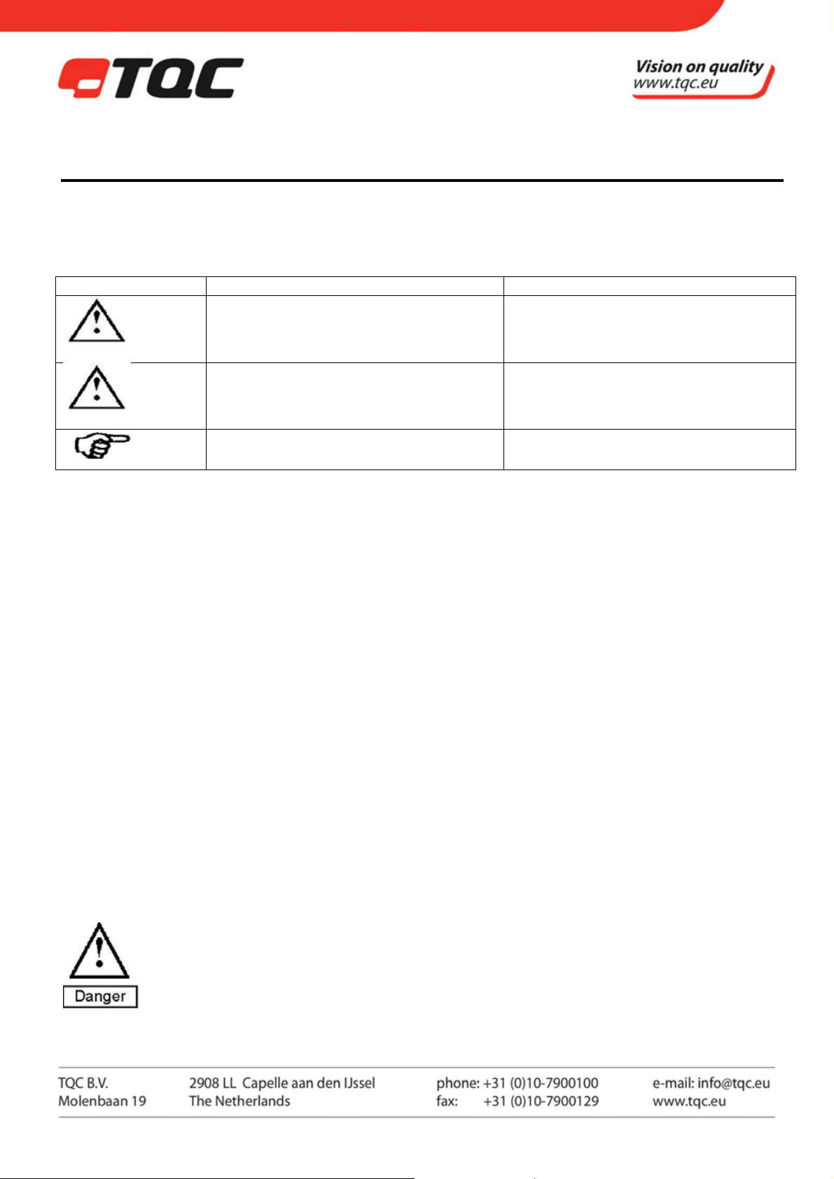
Symbol Explanation Warning
Possible immediate danger to the life or
health of personnel
Danger
A dangerous situation could be caused Non observance of this guideline can lead
Warning
Special tips and particular information Guidelines to make optimal use of the
2.2 Availability of Safety Information
The instruction manual should be kept at the place where the instrument is operated.
In addition to the information contained in the instruction manual, general and local regulations for accident
prevention and environmental protection shall be kept available and observed.
Always ensure all guidelines in respect of safety and dangers on the instrument are in readable condition.
In case of danger the instrument has to be switched off by means of the emergency-button on the front of the
instrument. Then eliminate danger.
2.3 Training of Personnel
• Anyone who operates the instrument should be trained properly.
• It has to be clear who has which responsibility regarding commissioning, set-up of maintenance and
repairs, installation, and operation.
• Anyone who hasn’t finished training should be supervised by an experienced person while working with
the instrument.
2.4 Dangers from Electrical Energy
• Work on the electrical supply may only be done by a qualified electrician.
• The electrical equipment of the instrument must be checked regularly. Loose connections and cable
damaged by heat must be corrected immediately.
• Always make sure the instrument's power is turned off while adjusting any electrical component.
2.5 Points of Special Danger
There is one special point of danger in the moving zone of the tool carriers:
Do not move the Applicators Tool Carrier Bar on the instrument manually!
Keep your hands away from the work area and tool carrier bar after the instrument has
started!
If this guideline is not noted it can lead to
severe danger to health, up to fatal injury
to injury or to damage to equipment.
instrument.
5 |
automatic-film-applicator-ab3120-m44 - Page 6 of 23
2.6 Care, Maintenance, Repairs
• Always make sure the instrument is connected to an earthed socket.
• Maintenance and inspection should be carried out at the correct intervals.
• Operating personnel should be informed before starting with maintenance or repair work .
• Always make sure the instruments power is turned off and the instrument is not connected to a socket
while adjusting any electrical component whenever maintenance, inspection or repair work is done.
• Do not open the instrument. In case of malfunction always consult the manufacturer.
• Never touch electronics or circuit boards when not ESD secured.
2.7 Modifications to the Equipment
• Any modifications or additions or alterations to the instrument may solely be made with permission from
the manufacturer.
• All measures involving modifications require written confirmation of approval from TQC.
• Instruments which are not in fault-free condition must immediately be switched off.
• Only use replacement parts from the original supplier. Parts used from other sources aren’t guaranteed to
take the loading and meet the safety requirements.
2.8 Cleaning of the Instrument and Disposal of Materials
• When in use it is not always possible to avoid some spill of paint on the work surface.
• Try to keep the instrument as clean as possible to prevent distortions of functions.
• To clean the instrument properly use a suitable solvent to dispose remains of paint or ink.
• Wear gloves during cleaning; Don’t spill an overdose of solvent during cleaning.
• Cleaning materials must always be used and disposed of correctly.
3 TRANSPORT AND STORAGE
3.1 Packing
Please take note of pictorial symbols on the packing.
3.2 User: Check on Receipt
Check packing for damage
After unpacking check complete supply.
3.3 Reporting Transport Damage and Documentation
Any damage should be documented as accurately as possible (possibly photographed) and reported to the
relevant insurers or, in the case of sales "delivered to customers works", to the supplier.
3.4 Storage and Protective Measures when not in use
The instrument must be stored in a dry (± 40%rH) place at a temperature between 10 - 40°C.
The storage period should not be longer than 3 months.
Store instrument in the original packing if possible.
6 |
automatic-film-applicator-ab3120-m44 - Page 7 of 23
4 INSTRUMENT DATA
4.1 Name / Article
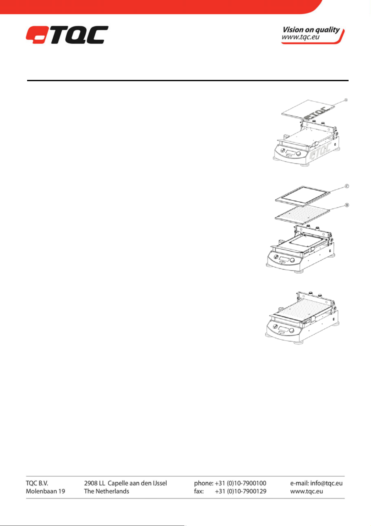
AB3120 TQC motorised automatic film applicator 230V with glass bed (A) and
combined attachment assembly for standard block applicators and wire
bar coaters.
AB3125 TQC motorised automatic film applicator 110V with glass bed (A) and
combined attachment assembly for standard block applicators and wire
bar coaters.
AB3220 TQC motorised automatic film applicator 230V with perforated vacuum
bed (B), built-in vacuum pump and combined attachment assembly for
standard block applicators and wire bar coaters.
AB3225 TQC motorised automatic film applicator 110V with perforated
vacuum bed (B), built-in vacuum pump and combined attachment
assembly for standard block applicators and wire bar coaters.
AB3320 TQC motorised automatic film applicator 230V with double channelled
vacuum bed (C), built-in vacuum pump and combined attachment
assembly for standard block applicators and wire bar coaters.
AB3325 TQC motorised automatic film applicator 110V with double channelled
vacuum bed (C), built-in vacuum pump and combined attachment
assembly for standard block applicators and wire bar coaters.
AB3400 TQC motorised automatic film applicator 230V with heated perforated
vacuum bed, built-in vacuum pump and combined attachment
assembly for standard block applicators and wire bar coaters.
AB3405 TQC motorised automatic film applicator 110V with heated perforated
vacuum bed, built-in vacuum pump and combined attachment
assembly for standard block applicators and wire bar coaters.
NOTE: TQC Automated Film Applicators equipped with a perforated vacuum
bed can be retrofitted with an optional double channeled vacuum bed
and vice versa.
Accessories (Optional)
AB3500 TQC Drying time recorder tool (Only suitable for models with firmware version 2.01 or above)
AB3000 Rubber mat for TQC Automated Film Applicator.
AB3100 Replacement Glass plate for TQC Automated Film Applicator
AB3200 Replacement perforated vacuum bed for TQC Automatic Film Applicator (Not for heated model).
AB3300 Replacement double channelled vacuum bed for TQC Automated Film Applicator.
4.2 Scope of Supply
The scope of supply varies due to the specific applications previously mentioned in the purchase order.
(I.e. Glass Plate, Vacuum Table, vacuum and accessories.)
7 |

automatic-film-applicator-ab3120-m44 - Page 8 of 23
4.3 Technical Data
Automatic Film Applicator
Traverse Speed: 2 – 500 mm/s
Traverse Speed accuracy: +/- 1% of set speed
Stroke length: 50 – 359 mm
Stroke length accuracy: +/- 2 mm
Max test chart size: DIN A3
Max test substrate thickness: 35mm including applied coating
Max. Width alternative film applicators: max. 300 mm
Max. Height alternative film applicators: max. 80 mm
Wire bar length: max. 325 mm spiral area in 364 mm length at fixation points
Wire bar diameter: max. Ø10 mm at the fixation points
Max vacuum: -178 mbar
Drying Time Recorder
Drying time range: 1 min. – 2880 min (48 hours)
Time accuracy: ≤ 1% of set time
Maximum test length: 350mm
Maximum number of tracks: 8
Heated perforated vacuum bed
Minimum temperature: Ambient + 5ºC
Maximum temperature: Ambient + 100ºC (Absolute max 140ºC)
Resolution of set temperature: 1ºC
Resolution of readout temperature: 0.1ºC
Temperature controller: Separate
Power consumption heating: 450 Watt
Power Supply: 230V, 50Hz
4.4 Dimensions and Weight
D x W X H 650 x 350 x 240 mm
Net weight: 31 kg – 36 kg dependent on model
4.5 Basic Unit
Power Supply: 115 – 230 V, 50 - 60 Hz
Power consumption: max. 80 Watt
Display: Blue Illuminated, graphic 100 x 35 mm, 193x64 pixels
Safety: Emergency Button and intelligent proximity switches, integrated
Acoustic Alarm
Function: Jog Shuttle knob by Rotation / Pushing
Drawn down Speeds: 12 steps selectable from 2 - 500 mm/s. and free selectable
(custom)
Drawn down Lengths: A5 / A4 / A3 and free selectable (custom with variable
starting/stopping point)
4.6 Noise Level
The continuous noise level from the instrument does not exceed 70 dB.
8 |

automatic-film-applicator-ab3120-m44 - Page 9 of 23
5 INSTALLATION AND ASSEMBLY
5.1 Installation and Operation
The instrument has to be installed in a suitable place, preferably on a sturdy table or work area, with normal
ambient temperature. Special fixings are not required.
Carefully unpack the apparatus and the accessories and check complete supply.
Place, if necessary, a spirit level on the work surface and adjust the height of the feet.
5.2 Preparation of Energy Connections
The instrument is equipped with a safety tested mains supply cable and may only be connected to plug sockets
with earth connection complying with the safety regulations.
Before connecting the instrument, check whether the
supply voltage specified on the indication label
corresponds to the local supply voltage.
Warning
If it does not, the instrument must not be connected
under any circumstances. Contact your local supplier or TQC
for full specifications on how to set the correct voltage.
5.3 Vacuum Connection
Only applicable for selected applicator series. The applicator has a built in vacuum pump to provide the vacuum
table enough under pressure to hold test charts of either A4 or A3 size. When the size differs from the stated A4
or A3, cover up all remaining holes to the nearest larger size in order to create adequate vacuum. The level of
vacuum created may depend on operation and age of the machine as well as test substrate used.
5.4 Mains Connection
The mains connection is located at the rear of the instrument. Plug in the female plug in the socket on the rear
of the housing. The ON/OFF Switch is located at the right hand site near the end of the instrument.
9 |

6 INSTRUMENT CONTROLS AND FUNCTIONS
6.1 Overview
1. Display with process information
2. Jog Shuttle
3. Emergency button
4. Acoustic alarm / Buzzer
5. Levelling supports
6. Glass plate or Vacuum table
7. Automated clamping device for test charts
8. Mains connection
9. Spiral applicator weight
10. Spiral bar release device
11. Hand protection device
12. Adjustable tool holder
13. Main Switch
automatic-film-applicator-ab3120-m44 - Page 10 of 23
2 51 3 4
9
7
12
8
6
13
10
11
10 |

7 INSTRUMENT COMPONENT ASSEMBLY
7.1 Overview
1. Housing
2. Splash shield
3. Tool Carrier
4. Hight Adjustment fixation
5. Spiral bar weight
6. Spiral bar weight guide pins
7. Spiral bar weight guide rings
8. Spiral bar weight extra weights
9. Lamp assembly
automatic-film-applicator-ab3120-m44 - Page 11 of 23
11 |

automatic-film-applicator-ab3120-m44 - Page 12 of 23
7.2 Instrument Preparations
Position the glass plate or vacuum suction table between the designated red supporting studs at the 4 corners
on the unit. The heated vacuum plate model comes with a pre assembled vacuum plate. For the other vacuum
models follow the vacuum seal installation instructions in Annex A.
7.3 Plate Glass Panel
This plate 470 x 300 x 12 mm can either be used directly as an application carrier or (for example) smaller cards
or foils.
Charts or foils are automatically clamped in a special device at the end of the unit as soon a test is performed.
For cleaning purposes the glass plate can be removed.
7.4 Vacuum Suction Plate
In order to create an adequate vacuum the instructions for setting up the vacuum seal O-rings as in Annex A
need to followed. The vacuum suction plate is automatically connected to the vacuum pump as soon as placed
between the red supporting studs on the O-rings. The vacuum plate serves to hold thick foils, charts and other
papers for coating.
The area size under vacuum depends on the selection made in the menu of the instrument (see 8.9).
7.5 Double Channel Vacuum
In order to create an adequate vacuum the instructions for setting up the vacuum seal O-rings as in Annex A
need to be followed . Double channel vacuum plates are used for testing on foils. When otherwise the foil will
not remain smooth on a normal vacuum table. The double channel only has vacuum in two concentrically rings
on the outside of the plate. This requires the foils to be about A3 size for the vacuum table to be able to hold
them.
To prevent pollution of some holes outside the dimensions of charts we advise to cover the surrounded area
with paper.
7.6 Film Applicators (Tools)
Spiral Bar applicators, Bird applicators, Baker applicators, Quadruplex applicators, SAG Quadruplex applicators
Adjustable Micrometer applicators, SAG and levelling applicators. Place the applicators as shown in below
pictures;
For details on film applicators datasheets are available on www.tqc.eu
12 |

automatic-film-applicator-ab3120-m44 - Page 13 of 23
NOTE: The length of TQC Spiral bar coaters has changed during the years. The older shorter version can be used
on the TQC Automatic Film Applicator by the use of optional available lengthening rods.
7.7 Test Charts
We supply a range of test charts (TQC, Leneta® or equivalent) like:
Opacity (hiding power) charts, Opacity Display charts, Sag and levelling charts, Brush out charts,
Plain White charts or others. CERTIFIED TQC TEST CHARTS!!!
For more details go to: http://www.tqc.eu/en/products/productlistarticles/214/1/false/Test-charts
7.8 Drying Time Recorder
The TQC Automated Film Applicator can be used as a Drying Time Recorder. In order to use the TQC Automatic
Film Applicator as a Drying Time Recorder following steps need to be followed:
• Remove the Spiral bar weight (5 from drawing chapter 7) by pulling out the Spiral bar weight guide
pins(6).
• Take care that both Spiral bar weight guide pins (6) and Spiral bar weight guide rings (7) are stored in a
safe place. In order to not to lose them.
• Place the optional available Drying Time Recorder Tool on the bar of the TQC Automatic Film Applicator
as illustrated in below image:
7.9 Multi Tool Platform
The ability of the TQC automated Film applicator to operate at a wide speed range not only allow for film
application and drying time tests to be conducted but also to serve as a stable platform for conducting tests like
the Pencil Hardness Test acc Wolff Wilborn (VF2377, VF2378 & VF2379), TQC Hardness Pen (SP0010) or
Grindometers (VF2110, VF2111, VF2112 & VF2113). For information on the use of these tools in combination
with the TQC Automated Film Applicator please contact your local sales representative.
13 |

8 MENU DISPLAY INFORMATION AND OPERATION
8.1 Automatic Film applicator operation
TQC Start screen after switched on.
Switch on instrument by mains switch at the right side on the
housing.
This is the first screen shown after switching on the instrument.
NOTE: The version number displayed is the firmware version
number.
RUN - Automatically the first selection screen or the
MAIN MENU appears
Press the Jog shuttle knob to start the sequence.
The applicator carrier bar is moved and set in position.
RUN - Positioning Chart
The current draw down speed as well as the length is shown in the
top of the display. Press the Jog shuttle knob to confirm or turn it
to go back in the menu and make changes.
Place the draw down chart on the glass plate or vacuum table.
Choose the appropriate applicator to fulfil the test.
RUN – Applicator and Paint applying
Apply just enough paint to fulfil the test on the test chart chosen.
Press the Jog shuttle knob to start the run or turn it to go back in the
menu and make changes. Display shows “Running”.
Keep your hands away from moving parts.
MAIN MENU – Run, Run setup, Instrument setup
In the main menu you can change parameters according to your
needs. Rotate the Jog shuttle knob to select and press to choose.
Follow the questions as they come.
RUN SETUP - Set Speed
Push the Jog shuttle knob to set the draw down speed.
automatic-film-applicator-ab3120-m44 - Page 14 of 23
14 |

automatic-film-applicator-ab3120-m44 - Page 15 of 23
RUN SET-SPEED
There are 12 preset speeds to choose from, 2 – 500 mm/s.
Custom is a free selectable speed in 1mm/s intervals.
After made changes rotate to BACK and press the Jog shuttle
knob.
RUN SETUP – Set Length
Push the Jog shuttle knob to set the traverse length.
RUN SETUP-LENGTH
There are 3 preset chart sizes selectable, A5 - A4 - A3 followed by
an auto return of the tool carrier bar. Selecting “Custom” offers
you to set a Start and End point on the platform. The traverse
length is automatically set in accordance with the start/end
points in millimetres.
After made changes rotate to BACK and press the Jog shuttle
knob
VACUUM will only switch dependent on the length of the test chart to A4 or A3.
NOTE: When using the custom length settings the spiral bar release studs can not be used and need to be set to the
end of the application table, as close as possible to the display
.
MAIN-MENU – Instrument setup
In the main menu rotate the jog shuttle knob to Instrument setup
and press on it.
INSTRUMENT SETUP
Select Language to set the desired language.
Select Units to set: Speed in mm/s, cm/s or inch/s and Length in
mm, cm or inches.
Select Acoustic signals: Signals off, Low volume or High Volume.
15 |

automatic-film-applicator-ab3120-m44 - Page 16 of 23
8.2 Drying Time recorder operation
The TQC drying time recorder is partially preset by the settings of the Automatic Film application. In order to set
up a new drying time test follow the steps below:
MAIN MENU – RUN SETUP
In the run setup menu the general setting of the Film applicator and
separate of the drying time recorder settings can be entered. Select
the “Set drying time recorder” menu to get into the set-up menu for
the drying time recorder.
RUN SETUP-DRYING TIME RECORDER
Within the Drying time recorder setup options as track time total run
time for drying time, alarm interval and vacuum control can be set.
Track time can be set from 1 minute to 48 hours. The speed will be
depended on track time and set track length. A shorter track length
will mean a lower speed. When performing drying time tests for
extended test times turn off the vacuum pump to prevent extensive
wear on the internal vacuum pump. Return to run setup menu by selecting back
NOTE: The vacuum control is only available for models equipped with vacuum.
RUN SETUP LENGTH
The length of a drying time test can be set here. The operation is the
same as that for setting the length for an application.
MAIN MENU
To perform a new drying time test select “Drying time recorder” in
the main menu. This will start a drying time run with the setting of
the previous menus.
DTR-RUN (1)
The drying time recorder will now be initiated. Follow the instruction
on the screen, and position a test chart or a test substrate. When
placed, select confirm to continue.
DTR-RUN (2)
The chart / test substrate is now fixed and the drying time recorder
tool can now be placed. Click the tool in place as shown in below
illustrations. When ready select run to continue.
DTR-RUN (3)
The drying time recorder is now running. The display shows the set
time in the top left corner and the Running time in the centre of the
screen. To end the run select stop. IT can appear that the drying time
recorder is not reacting to your command. The internal processor
causes this. The processor is at that time busy performing other
tasks, and will execute your command as soon as the performed task
is completed.
16 |

automatic-film-applicator-ab3120-m44 - Page 17 of 23
DTR-RUN (4)
When the RUN is ended the tool holder can be moved to the points
of interest on the test track by rotating the jog shuttle. The display
will show the elapsed time of when the tool holder first passed that
point. Select back to confirm.
DTR-RUN (5)
At this step the vacuum or clamp will be released and the chart /
substrate can be removed from the test bed.
8.3 Heated Film bed control
The TQC Heated film bed controller is operated by two buttons. The
power switch on the top and the temperature set knob on the front.
To set the temperature first turn the machine on and then set the
temperature. The test bed will warm up to the set temperature.
8.4 Warning signals
Due to circumstances the display can show:
“Release the Emergency Stop” Caused by manually pressing of the Red emergency
button. Check the fault or wrong handling, and, after
assuring that there is no danger, release the emergency stop
“Lifter is in wrong position” Caused by wrong movement or positioning
after spiral bar lifting situations. The lifter is in position when you feel a click.
See Annex B on lifter positioning
“Hand detection” For safety reasons 3 sets of detection sensors
at each site on the housing register the proximity of fingers and
shuts down any activity of the instrument.
17 |

automatic-film-applicator-ab3120-m44 - Page 18 of 23
9 OPERATION
9.1 Preparatory Work
• Connect the instrument to the mains at the rear side of the housing.
• When using the glass plate position the test chart or foil totally to the rear and automatic clamping device.
• When using the vacuum suction plate position the test chart totally to the rear and let the chart or foil suck
in for some seconds.
• Install and fix the tool carrier and the appropriate film applicator.
9.2 Film Application
For film application a suitable flat and even base, the glass plate or the vacuum suction plate, as well as a
suitable to use type applicator is necessary.
9.3 Start the instrument
Start the instrument following the steps listed in Section 8.
10 CARE AND MAINTENANCE
10.1 Inspection and Maintenance
• Though robust in design, this instrument is precision-machined. Never drop it or knock it over.
• Always clean the instrument after use.
• Clean the instrument using a soft dry cloth. Never clean the instrument by any mechanical means such as a
wire brush or abrasive paper. This may cause, just like the use of aggressive cleaning agents, permanent
damage.
• Do not use compressed air to clean the instrument.
• Generally the TQC Film applicator does not require any maintenance.
• After finishing the film application, take off the film applicators and clean them immediately.
Make sure that no paint or other liquids are spilled on the electronics or left in the holes of the
vacuum plate.
Warning
The film applicators are subject to some natural wear and must be inspected from time to time
to ensure that they are in fault-free condition.
10.2 Disposal of Materials
Disposal of materials used in the operation of the instrument or for auxiliary functions and exchanged items
should be dealt with safely and in a manner that will not harm the environment. Follow the local regulations.
10.3 Customer Service
Customer service is provided on request by:
TQC
Molenbaan 19
2908 LL Capelle aan den IJssel
The Netherlands,
T +31 (0)10 7900100
F +31 (0)10 7900129
18 |

automatic-film-applicator-ab3120-m44 - Page 19 of 23
11 DISCLAIMER
The right of technical modifications is reserved.
The information given in this manual is not intended to be exhaustive and any person using the product for any
purpose other than that specifically recommended in this manual without first obtaining written confirmation
from us as to the suitability of the product for the intended purpose does so at his own risk. Whilst we
endeavour to ensure that all advice we give about the product (whether in this manual or otherwise) is correct
we have no control over either the quality or condition of the product or the many factors affecting the use and
application of the product. Therefore, unless we specifically agree in writing to do so, we do not accept any
liability whatsoever or howsoever arising for the performance of the product or for any loss or damage (other
than death or personal injury resulting from our negligence) arising out of the use of the product. The
information contained in this manual is liable to modification from time to time in the light of experience and
our policy of continuous product development.
19 |

automatic-film-applicator-ab3120-m44 - Page 20 of 23
ANNEX A | INSTALLATION OF THE VACUUM BED
After unpacking the TQC automatic Film applicator the rubber seals for the vacuum bed need to be placed.
Without these seals the vacuum can NOT be created.
Remove all tape holding the perforated or double channel vacuum plate. Take great care to remove all the tape.
Remove the vacuum plate from the base plate, and stow it in a safe place.
Take the two black rubber rings from the package and differentiate in size.
Place the smallest of the rings (A4) around the inner supports and the largest (A3) around the outer supports, as
shown in below image (detail A).
Gently lower down the vacuum plate (B or C). Take care not to disturb the placement of the rubbers.
Turn the device on and follow the instruction to start a new test, using an A3 test chart, however hold at the step
where the vacuum pump turn on.
Place an A3 test chart and press it down. It should be sucked to the vacuum table. If not grab the sides of both
plates and press them together.
When the pitch of the vacuum pump changes and sounds softer the vacuum seal is complete.
Continue the run and afterwards you are ready.
20 |

ANNEX B | POSITIONING OF SPIRAL BAR LIFTER
automatic-film-applicator-ab3120-m44 - Page 21 of 23
21 |

ANNEX C |INSTALLATION OF THE LAMP
automatic-film-applicator-ab3120-m44 - Page 22 of 23
22 |

automatic-film-applicator-ab3120-m44 - Page 23 of 23
23 |
 Loading...