

TQ TQMxE39S series, TQMxE39S-AA, TQMxE39S-AB, TQMxE39S-AC, TQMxE39S-AD User Manual
...
TQMxE39S
User's Manual
TQMxE39S UM 0101
2019-01-15

User's Manual l TQMxE39S UM 0101 l © 2019 TQ-Group Page i
TABLE OF CONTENTS
1. ABOUT THIS MANUAL................................................................................................................................................................................1
1.1 Copyright and Licence Expenses ........................................................................................................................................................... 1
1.2 Registered Trademarks..............................................................................................................................................................................1
1.3 Disclaimer...................................................................................................................................................................................................... 1
1.4 Imprint............................................................................................................................................................................................................1
1.5 Service and Support...................................................................................................................................................................................1
1.6 Tips on Safety ...............................................................................................................................................................................................2
1.7 Symbols and Typographic Conventions..............................................................................................................................................2
1.8 Handling and ESD Tips .............................................................................................................................................................................. 2
1.9 Naming of Signals....................................................................................................................................................................................... 3
1.10 Further Applicable Documents / Presumed Knowledge................................................................................................................ 3
2. INTRODUCTION ........................................................................................................................................................................................... 3
2.1 Functional Overview.................................................................................................................................................................................. 4
2.2 Specification Compliance.........................................................................................................................................................................5
2.3 Variants...........................................................................................................................................................................................................5
2.4 Accessories....................................................................................................................................................................................................5
3. FUNCTION .....................................................................................................................................................................................................6
3.1 Block Diagram..............................................................................................................................................................................................6
3.2 Electrical Characteristics ...........................................................................................................................................................................6
3.2.1 Supply Voltage Characteristics ...............................................................................................................................................................6
3.2.2 Power Consumption ..................................................................................................................................................................................7
3.2.2.1 Real Time Clock............................................................................................................................................................................................8
3.3 Environment.................................................................................................................................................................................................8
3.4 System Components.................................................................................................................................................................................. 9
3.4.1 CPU ..................................................................................................................................................................................................................9
3.4.2 Graphics .........................................................................................................................................................................................................9
3.4.3 Memory....................................................................................................................................................................................................... 10
3.4.3.1 LPDDR4 SDRAM........................................................................................................................................................................................ 10
3.4.3.2 eMMC........................................................................................................................................................................................................... 10
3.4.3.3 SPI Boot Flash ............................................................................................................................................................................................ 10
3.4.3.4 EEPROM....................................................................................................................................................................................................... 10
3.4.4 Real Time Clock......................................................................................................................................................................................... 10
3.4.5 Hardware Monitor.................................................................................................................................................................................... 10
3.4.6 TQ flexible I/O configuration (TQ-flexiCFG) ..................................................................................................................................... 10
3.5 Interfaces .................................................................................................................................................................................................... 11
3.5.1 PCI Express ................................................................................................................................................................................................. 11
3.5.2 Gigabit Ethernet ....................................................................................................................................................................................... 11
3.5.3 Serial ATA.................................................................................................................................................................................................... 11
3.5.4 Digital Display Interface......................................................................................................................................................................... 11
3.5.5 LVDS Interface........................................................................................................................................................................................... 11
3.5.6 USB 2.0 Interfaces..................................................................................................................................................................................... 12
3.5.7 USB 3.0 Interfaces..................................................................................................................................................................................... 12
3.5.8 SD Card Interface...................................................................................................................................................................................... 12
3.5.9 General Purpose Input/Output............................................................................................................................................................ 12
3.5.10 Audio Interface ......................................................................................................................................................................................... 12
3.5.11 MIPI CSI Camera Interface ..................................................................................................................................................................... 12
3.5.12 I2C Bus.......................................................................................................................................................................................................... 12
3.5.13 SMBus / Power Management I2C Bus................................................................................................................................................. 12
3.5.14 Serial Peripheral Interface ..................................................................................................................................................................... 12
3.5.15 Serial Ports.................................................................................................................................................................................................. 13
3.5.16 Watchdog Timer....................................................................................................................................................................................... 13

User's Manual l TQMxE39S UM 0101 l © 2019 TQ-Group Page ii
TABLE OF CONTENTS (continued)
3.6 Connectors................................................................................................................................................................................................. 13
3.6.1 SMARC Connector.................................................................................................................................................................................... 13
3.6.2 TQM Debug Card...................................................................................................................................................................................... 13
3.6.3 Debug Module LED ................................................................................................................................................................................. 14
3.7 SMARC Connector Pinout List.............................................................................................................................................................. 14
3.7.1 Signal Assignment Abbreviations....................................................................................................................................................... 14
3.7.2 SMARC Connector Pin Assignment.................................................................................................................................................... 15
4. MECHANICS ............................................................................................................................................................................................... 21
4.1 TQMxE39S Dimensions .......................................................................................................................................................................... 21
4.2 Heat Spreader Dimensions ................................................................................................................................................................... 22
4.3 Mechanical and Thermal Considerations ......................................................................................................................................... 23
4.4 Protection Against External Effects .................................................................................................................................................... 23
5. SOFTWARE.................................................................................................................................................................................................. 24
5.1 System Resources .................................................................................................................................................................................... 24
5.1.1 I2C Bus.......................................................................................................................................................................................................... 24
5.1.2 SMBus .......................................................................................................................................................................................................... 24
5.1.3 Memory Map ............................................................................................................................................................................................. 24
5.1.4 IRQ Map....................................................................................................................................................................................................... 24
5.2 Operating Systems .................................................................................................................................................................................. 25
5.2.1 Supported Operating Systems............................................................................................................................................................. 25
5.2.2 Driver Download ...................................................................................................................................................................................... 25
5.3 BIOS .............................................................................................................................................................................................................. 25
5.3.1 Enter BIOS Setup ...................................................................................................................................................................................... 25
5.4 Software Tools........................................................................................................................................................................................... 25
6. SAFETY REQUIREMENTS AND PROTECTIVE REGULATIONS......................................................................................................... 26
6.1 EMC............................................................................................................................................................................................................... 26
6.2 ESD................................................................................................................................................................................................................ 26
6.3 Shock & Vibration..................................................................................................................................................................................... 26
6.4 Operational Safety and Personal Security ........................................................................................................................................ 26
6.5 Reliability and Service Life..................................................................................................................................................................... 26
6.5.1 RoHS............................................................................................................................................................................................................. 26
6.5.2 WEEE®.......................................................................................................................................................................................................... 26
6.6 Other Entries.............................................................................................................................................................................................. 26
7. APPENDIX ................................................................................................................................................................................................... 27
7.1 Acronyms and Definitions..................................................................................................................................................................... 27
7.2 References.................................................................................................................................................................................................. 29

User's Manual l TQMxE39S UM 0101 l © 2019 TQ-Group Page iii
TABLE DIRECTORY
Table 1: Terms and Conventions.....................................................................................................................................................................2
Table 2: TQMxE39S Module Variants ............................................................................................................................................................. 5
Table 3: TQMxE39S Power Consumption..................................................................................................................................................... 7
Table 4: RTC Current Consumption................................................................................................................................................................8
Table 5: Intel
®
Atom™ E3900, Intel
®
Pentium® N4200, and Intel® Celeron® N3350 ......................................................................9
Table 6: Maximum Resolution in Dual Display Configuration ...............................................................................................................9
Table 7: PCI Express Configuration Options ............................................................................................................................................. 11
Table 8: LED Boot Messages .......................................................................................................................................................................... 14
Table 9: Abbreviations used .......................................................................................................................................................................... 14
Table 10: SMARC Connector Pin Assignment............................................................................................................................................. 15
Table 11: I2C Address Mapping on GP I2C Port........................................................................................................................................... 24
Table 12: I2C Address Mapping on SMBus Port.......................................................................................................................................... 24
Table 13: Acronyms ............................................................................................................................................................................................ 27
Table 14: Further Applicable Documents and Links................................................................................................................................. 29
ILLUSTRATION DIRECTORY
Illustration 1: Block Diagram TQMxE39S................................................................................................................................................................. 6
Illustration 2: TQM Debug Card.............................................................................................................................................................................. 13
Illustration 3: Three View Drawing TQMxE39S................................................................................................................................................... 21
Illustration 4: Bottom View Drawing TQMxE39S............................................................................................................................................... 21
Illustration 5: Standard Heat Spreader TQMxE39S-HSP.................................................................................................................................. 22
REVISION HISTORY
Rev. Date Name Pos. Modification
0100 2018-02-16 FP Initial release
0101 2019-01-15 WM 3.4.3.3 Type of supported SPI Boot Flash corrected

User's Manual l TQMxE39S UM 0101 l © 2019 TQ-Group Page 1
1. ABOUT THIS MANUAL
1.1 Copyright and Licence Expenses
Copyright protected © 2019 by TQ-Systems GmbH.
This User's Manual may not be copied, reproduced, translated, changed or distributed, completely or partially in electronic,
machine readable, or in any other form without the written consent of TQ-Systems GmbH.
The drivers and utilities for the components used as well as the BIOS are subject to the copyrights of the respective
manufacturers. The licence conditions of the respective manufacturer are to be adhered to.
BIOS-licence expenses are paid by TQ-Systems GmbH and are included in the price.
Licence expenses for the operating system and applications are not taken into consideration and must be calculated / declared
separately.
1.2 Registered Trademarks
TQ-Systems GmbH aims to adhere to copyrights of all graphics and texts used in all publications, and strives to use original
or license-free graphics and texts.
All brand names and trademarks mentioned in this User's Manual, including those protected by a third party, unless specified
otherwise in writing, are subjected to the specifications of the current copyright laws and the proprietary laws of the present
registered proprietor without any limitation. One should conclude that brand and trademarks are rightly protected by a third
party.
1.3 Disclaimer
TQ-Systems GmbH does not guarantee that the information in this User's Manual is up-to-date, correct, complete
or of good quality. Nor does TQ-Systems GmbH assume guarantee for further usage of the information. Liability claims against
TQ-Systems GmbH, referring to material or non-material related damages caused, due to usage or non-usage of the information
given in this User's Manual, or due to usage of erroneous or incomplete information, are exempted, as long as there is no proven
intentional or negligent fault of TQ-Systems GmbH.
TQ-Systems GmbH explicitly reserves the rights to change or add to the contents of this User's Manual or parts of it without
special notification.
1.4 Imprint
TQ-Systems GmbH
Gut Delling, Mühlstraße 2
D-82229 Seefeld
Tel: +49 8153 9308–0
Fax: +49 8153 9308–4223
Email:
Web:
info@tq-group.com
www.tq-group.com/
1.5 Service and Support
Please visit our website www.tq-group.com for latest product documentation, drivers, utilities and technical support.
Through our website
www.tq-group.com you could also get registered, to have access to restricted information and automatic
update services.
For direct technical support you could contact our FAE team by email:
support@tq-group.com
Our FAE team can support you also with additional information like 3D-STEP files and confidential information which is not
provided on our public website.
For service/RMA, please contact our service team by email (
service@tq-group.com) or your dedicated sales team at TQ.
User's Manual l TQMxE39S UM 0101 l © 2019 TQ-Group Page 2
1.6 Tips on Safety
Improper or incorrect handling of the product can substantially reduce its life span.
1.7 Symbols and Typographic Conventions
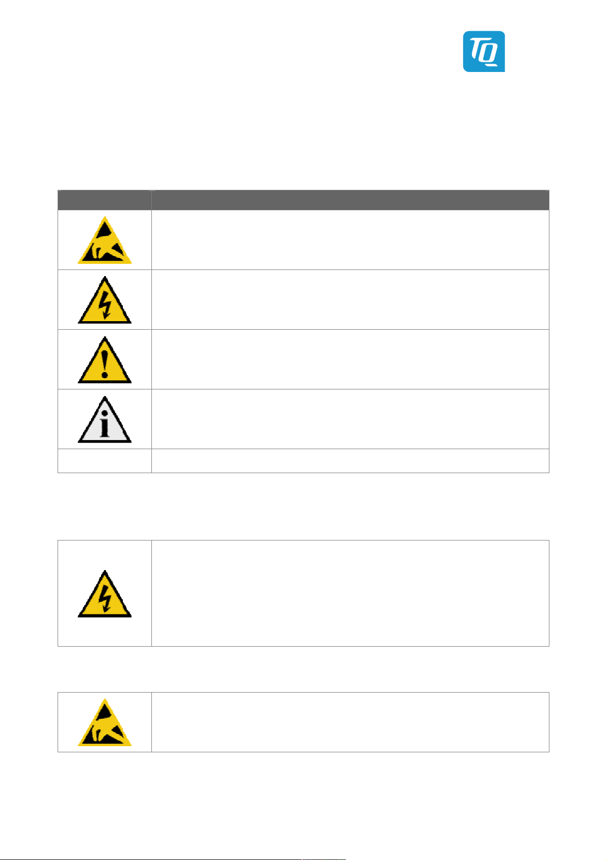
Table 1: Terms and Conventions
Symbol Meaning
This symbol represents the handling of electrostatic-sensitive modules and / or components. These
components are often damaged / destroyed by the transmission of a voltage higher than about 50 V.
A human body usually only experiences electrostatic discharges above approximately 3,000 V.
This symbol indicates the possible use of voltages higher than 24 V.
Please note the relevant statutory regulations in this regard.
Non-compliance with these regulations can lead to serious damage to your health and also cause
damage / destruction of the component.
This symbol indicates a possible source of danger. Acting against the procedure described can lead to
possible damage to your health and / or cause damage / destruction of the material used.
This symbol represents important details or aspects for working with TQ-products.
Command
A font with fixed-width is used to denote commands, contents, file names, or menu items.
1.8 Handling and ESD Tips
General handling of your TQ-products
The TQ-product may only be used and serviced by certified personnel who have taken note of the
information, the safety regulations in this document and all related rules and regulations.
A general rule is: do not touch the TQ-product during operation. This is especially important when
switching on, changing jumper settings or connecting other devices without ensuring beforehand
that the power supply of the system has been switched off.
Violation of this guideline may result in damage / destruction of the TQMxE39S and be dangerous to
your health.
Improper handling of your TQ-product would render the guarantee invalid.
Proper ESD handling
The electronic components of your TQ-product are sensitive to electrostatic discharge (ESD).
Always wear antistatic clothing, use ESD-safe tools, packing materials etc., and operate your TQ-
product in an ESD-safe environment. Especially when you switch modules on, change jumper settings,
or connect other devices.

User's Manual l TQMxE39S UM 0101 l © 2019 TQ-Group Page 3
1.9 Naming of Signals
A hash mark (#) at the end of the signal name indicates a low-active signal.
Example: RESET#
If a signal can switch between two functions and if this is noted in the name of the signal, the low-active function is marked with
a hash mark and shown at the end.
Example: C / D#
If a signal has multiple functions, the individual functions are separated by slashes when they are important for the wiring.
The identification of the individual functions follows the above conventions.
Example: WE2# / OE#
1.10 Further Applicable Documents / Presumed Knowledge
• Specifications and manual of the modules used:
These documents describe the service, functionality and special characteristics of the module used.
• Specifications of the components used:
The manufacturer's specifications of the components used, for example CompactFlash cards, are to be taken note of.
They contain, if applicable, additional information that must be taken note of for safe and reliable operation.
These documents are stored at TQ-Systems GmbH.
• Chip errata:
It is the user's responsibility to make sure all errata published by the manufacturer of each component are taken note of.
The manufacturer’s advice should be followed.
• Software behaviour:
No warranty can be given, nor responsibility taken for any unexpected software behaviour due to deficient components.
• General expertise:
Expertise in electrical engineering / computer engineering is required for the installation and the use of the device.
Implementation information for the carrier board design is provided in the SMARC Design Guide (2) maintained by the SGET
(Standardization Group for Embedded Technologies). This Carrier Design Guide includes a very good guideline to design SMARC
carrier board.
It includes detailed information with schematics and detailed layout guidelines.
Please refer to the official SGET documentation for additional information (1).
2. INTRODUCTION
The TQ module TQMxE39S is based on the latest generation of Intel
®
Atom™, Pentium
“Apollo Lake”). It achieves a new level of computing performance, security and media processing performance in a very compact
form factor to empower real-time computing, industrial automation, digital surveillance, aviation, medical, retail and more.
The TQMxE39S corresponds to the internationally established SGET standard SMARC (V2.0). 6 USB ports – including 2 USB 3.0 –
and up to 4 PCIe lanes natively supported by the CPUs enable high bandwidth communication with peripherals and additional
interfaces on the carrier board. With the latest Intel® graphics processor integrated, the TQMxE39S delivers 4K high resolution
graphics output, immersive 3D processing and also greatly increased video encode and playback performance.
Time coordinated computing capabilities enable time synchronized processes within IoT networks and industrial control
applications. On-board eMMC up to 64 Gbyte and the option for LVDS or native eDP enable flexibility and reduce overall BOM
cost.
The integrated TQMx86 board controller enables high flexibility through “flexiCFG” and supports thermal management,
watchdog, 16550 compatible UARTs I2C controllers and GPIO handling. Combined with options like conformal coating and
optimized cooling solutions the TQMxE39S perfectly fits for mobile, low power, low profile and battery driven applications in
multiple vertical markets like industrial automation, medical devices, transportation and others.
®
and Celeron® CPUs (code name

User's Manual l TQMxE39S UM 0101 l © 2019 TQ-Group Page 4
2.1 Functional Overview
The following key functions are implemented on the TQMxE39S:
CPU:
• Intel® Atom™ E3900 („Apollo Lake-I“)
• Intel
• Intel
®
Pentium® N4200 („Apollo Lake“)
®
Celeron® N3350 („Apollo Lake“)
Memory:
• LPDDR4: 2 Gbyte, 4 Gbyte, 8 Gbyte
• eMMC 5.0 on-board flash up to 64 Gbyte
• EEPROM: 32 kbit (24LC32)
Graphics:
• 1 × Digital Display Interface (DDI) (DP 1.2a, DVI, HDMI 1.4b)
• 1 × HDMI Interface (DVI, HDMI 1.4b)
• 1 × Embedded Digital Display Interface (eDDI) or LVDS interface (eDP 1.3 or LVDS)
Peripheral interfaces:
• 1 × Gigabit Ethernet (Intel
®
i210), external IEEE1588 sync optional
• 1 × SATA 3.0 (up to 6 Gb/s), eSATA capable
• 4 × PCIe 2.0 (up to 5 Gb/s) (4
th
lane optional, if no Ethernet)
• 2 × Camera interface MIPI CSI (2 and 4 lane)
• 4 × USB 2.0, 2 x USB 3.0 (1 x Host / 1 x Host/Client)
• 1 × Intel
• 1 × I
®
HD audio (I) or I2S
2
C (General Purpose; master/slave capable)
• 1 × SMBus
• 1 × SPI (for external uEFI BIOS flash)
• 4 × Serial port (Rx/Tx, legacy compatible)
• 1 × SD card interface
• 12 GPIO signals (multiplexed with fan / camera control and HD audio Reset)
Others:
• TQMx86 board controller with Watchdog and TQ-flexiCFG
• Hardware monitor
Power supply:
• Voltage: 4.75 V to 5.25 V
3 V Battery for RTC
Environment:
• Standard Temperature: 0 °C to +60 °C
• Extended Temperature: –40 °C to +85 °C
Form factor / dimensions:
• SMARC short form factor; 82 mm × 50 mm
User's Manual l TQMxE39S UM 0101 l © 2019 TQ-Group Page 5
2.2 Specification Compliance
The TQMxE39S is compliant to the SMARC Hardware Specification (Version 2.0).
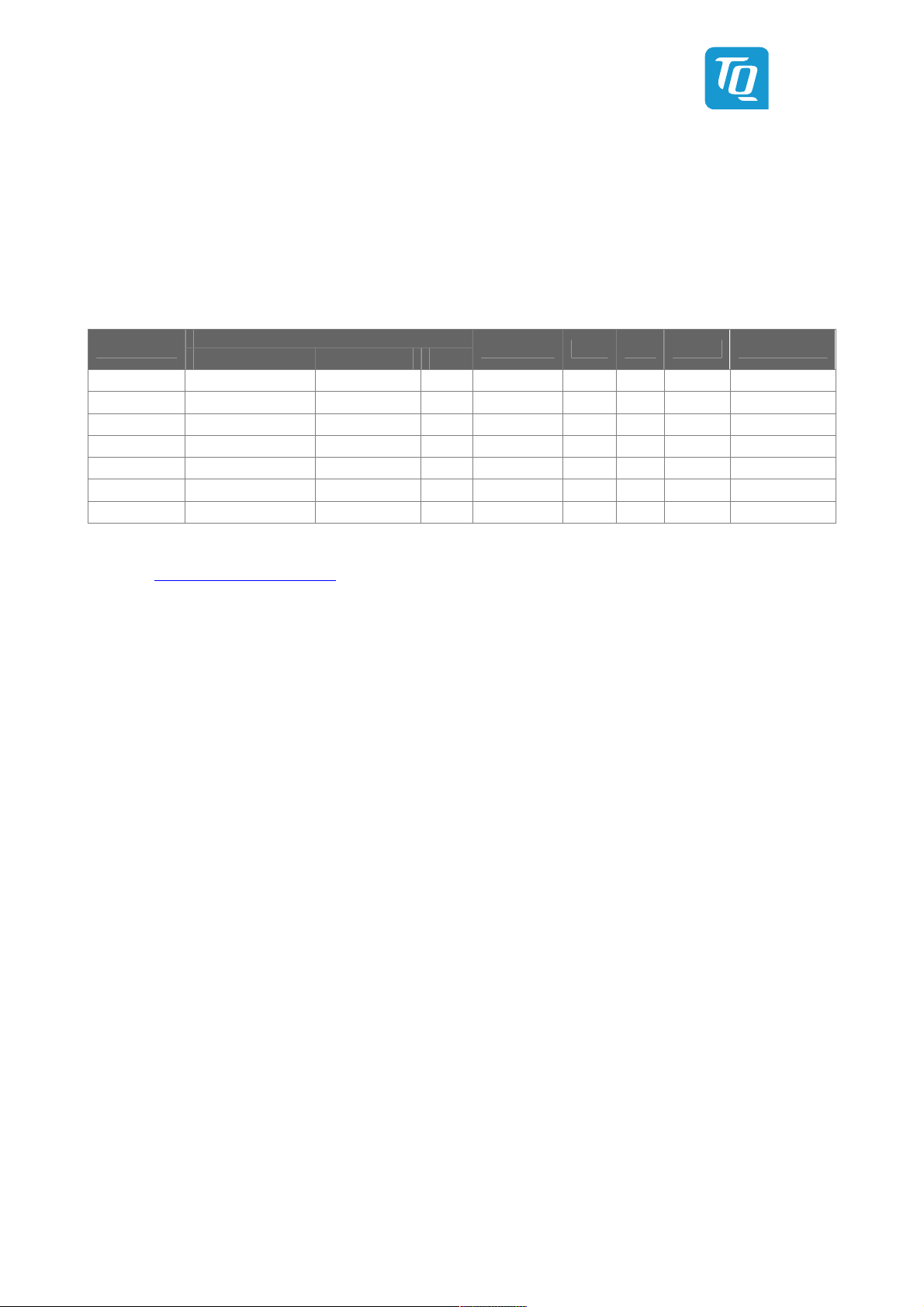
2.3 Variants
The TQMxE39S is available in several standard configurations:
Table 2: TQMxE39S Module Variants
Module
TQMxE39S-AA Intel Atom x7-E3950 4 × 1.6 / 2.0 GHz 2 MB 8 GB LPDDR4 32 GB 12 W LVDS –40 °C to +85 °C
TQMxE39S-AB Intel Atom x5-E3940 4 × 1.6 / 1.8 GHz 2 MB 8 GB LPDDR4 32 GB 9.5 W eDP –40 °C to +85 °C
TQMxE39S-AC Intel Atom x5-E3930 2 × 1.3 / 1.8 GHz 2 MB 4 GB LPDDR4 8 GB 6.5 W LVDS –40 °C to +85 °C
TQMxE39S-AD Intel Celeron N3350 2 × 1.1 / 2.4 GHz 2 MB 4 GB LPDDR4 8 GB 6 W LVDS 0 °C to +60 °C
TQMxE39S-AE Intel Pentium N4200 4 × 1.1 / 2.5 GHz 2 MB 8 GB LPDDR4 32 GB 6 W eDP 0 °C to +60 °C
TQMxE39S-AF Intel Atom x5-E3940 4 × 1.6 / 1.8 GHz 2 MB 8 GB LPDDR4 32 GB 9.5 W LVDS –40 °C to +85 °C
TQMxE39S-AG Intel Atom x7-E3950 4 × 1.6 / 2.0 GHz 2 MB 8 GB LPDDR4 32 GB 12 W eDP –40 °C to +85 °C
Core Clock Cache
CPU
SDRAM eMMC TDP Graphics Temp. Range
Please visit
www.tq-group.com/TQMxE39S for a complete list of standard variants.
Other configurations are available on request.
Standard configuration features are:
• eDP or LVDS
• CPU version
• Memory configuration
• Temperature range
Optional hardware and software configuration features:
• Conformal coating can be offered as custom specific add-on
• Custom specific BIOS configuration
2.4 Accessories
TQMxE39S-HSP-E, TQMxE39S-HSP-N: Heat spreader for TQMxE39S according to the SMARC specification
Evaluation platform MB-SMARC-1:
• Mainboard for SMARC modules
• 170 mm × 170 mm
• Interfaces: DP, HDMI, eDP/LVDS, 2 × GbE, 1 × USB Type C, 1 x USB 3.0, 1 x USB 2.0, audio, Micro SD card, 4 x M.2 socket
(Key E, B, B, M), 4 × RS232, 2 × CSI
User's Manual l TQMxE39S UM 0101 l © 2019 TQ-Group Page 6
3. FUNCTION
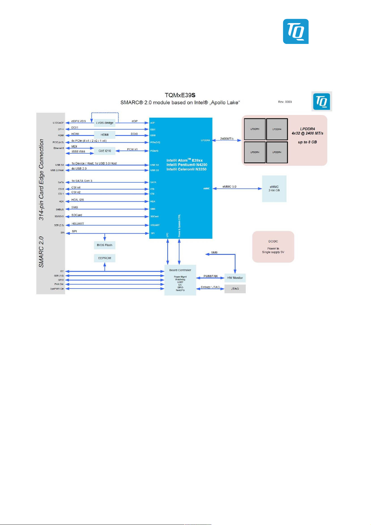
3.1 Block Diagram
The following illustration shows the block diagram of the TQMxE39S:
Illustration 1: Block Diagram TQMxE39S
3.2 Electrical Characteristics
3.2.1 Supply Voltage Characteristics
The TQMxE39S supports an input voltage from 4.75 V to 5.25 V.
The following supply voltages are specified at the SMARC connector:
• Main Power Rail: 4.75 V to 5.25 V max input ripple: ±100 mV
• VCC_RTC: 2.0 V to 3.3 V max input ripple: ±20 mV
The input voltages shall rise from 10 % of nominal to 90 % of nominal within 0.1 ms to 20 ms (0.1 ms ≤ Rise Time ≤ 20 ms).
There must be a smooth and continuous ramp of each DC output voltage from 10 % to 90 % of its final set point within the
regulation band.
User's Manual l TQMxE39S UM 0101 l © 2019 TQ-Group Page 7
3.2.2 Power Consumption
The values below show voltage and power consumption details for the TQMxE39S.
The values were measured using the TQMxE39S and the MB-SMARC-1 carrier board.
The measurement was done with two power supplies, one for the TQMxE39S and the other one for the MB-SMARC-1 carrier
board.
The power consumption of each TQMxE39S was measured running Windows® 10, 64 bit and a four chip LPDDR4 configuration (4
× 2 Gbyte). All measurements were done at a temperature of +25 °C and an input voltage of +5.0 V.
The power consumption of the TQMxE39S depends on the application, the mode of operation and the operating system.
The power consumption was measured under the following conditions:
• Suspend mode:
The system is in S5/S4 state, Ethernet port is disconnected.
• Windows 10, 64 bit, idle:
Desktop idles, Ethernet port is disconnected.
• Windows 10, 64 bit, maximum load:
These values show the maximum worst case power consumption, achieved by using the Intel® stress test tool to apply
maximum load to the cores only, and cores plus graphics engine, Ethernet port is connected (1000 Mbps Speed)
• Windows 10, 64 bit, Suspend Mode:
The system is in S5/S4 state, Ethernet port is disconnected.
The following table shows the power consumption with different CPU configurations.
Table 3: TQMxE39S Power Consumption
Module
Suspend (OS shut down) Win10, 64 bit idle Win10, 64 bit max. load
Mode
Intel® Pentium® N4200 0.33 W 2 W TBD
Intel® Celeron® N3350 0.33 W 2 W TBD
E3930 with 8 Gbyte LPDDR4 0.33 W 2 W 8 W
E3940 with 8 Gbyte LPDDR4 0.33 W 2 W 11.5 W
E3950 with 8 Gbyte LPDDR4 0.33 W 2 W 16 W
Note: Power requirement
The power supplies on the carrier board for the TQMxE39S must be designed with enough reserve.
The carrier board should provide at least twice the maximum workload power of the TQMxE39S.
The TQMxE39S supports several low-power states. The power supply of the carrier board has to be
stable even with no load.
 Loading...