

User's Guide l MBox-R/V UG 0103 l © 2017 TQ-Group Page i
MBox
-
R/V
User's Guide
MBox-R/V UG 0103
2017-11-17


User's Guide l MBox-R/V UG 0103 l © 2017 TQ-Group Page i
TABLE OF CONTENTS
1. IMPORTANT INFORMATION..................................................................................................................................................................... 1
1.1 General ...........................................................................................................................................................................................................1
1.2 Symbols and Typographic Conventions.............................................................................................................................................. 1
1.3 Before You Start...........................................................................................................................................................................................1
1.4 Duty Of Care ................................................................................................................................................................................................. 1
1.5 Limited Warranty.........................................................................................................................................................................................1
1.6 Liability and Warranty Obligation.......................................................................................................................................................... 1
1.7 Safety Guidelines.........................................................................................................................................................................................2
1.8 Grounding Considerations.......................................................................................................................................................................2
1.9 ESD Considerations ....................................................................................................................................................................................2
1.10 Handling the MBox-R/V............................................................................................................................................................................. 2
1.11 Coin Cell Battery .......................................................................................................................................................................................... 2
2. ABOUT THIS MANUAL................................................................................................................................................................................3
2.1 Copyright and Licence Expenses ...........................................................................................................................................................3
2.2 Registered Trademarks.............................................................................................................................................................................. 3
2.3 Disclaimer......................................................................................................................................................................................................3
2.4 Imprint............................................................................................................................................................................................................ 3
2.5 Service, Support, and RMA....................................................................................................................................................................... 3
3. INTRODUCTION ...........................................................................................................................................................................................4
3.1 Functional Overview..................................................................................................................................................................................4
3.2 MBox-R/V Versions......................................................................................................................................................................................5
4. FUNCTIONAL SPECIFICATION..................................................................................................................................................................6
4.1 Electrical Specification...............................................................................................................................................................................6
4.1.1 Supply Voltage Characteristics ............................................................................................................................................................... 6
4.1.2 Power Consumption Specification........................................................................................................................................................6
4.2 Environmental Specification ...................................................................................................................................................................6
4.3 Connectors and Interfaces .......................................................................................................................................................................7
4.3.1 External Connectors and Interfaces Arrangement ........................................................................................................................... 7
4.3.1.1 Power Supply Connector.......................................................................................................................................................................... 9
4.3.1.2 Mini DisplayPort .......................................................................................................................................................................................... 9
4.3.1.3 USB Host Interfaces ....................................................................................................................................................................................9
4.3.1.4 Gigabit Ethernet ..........................................................................................................................................................................................9
4.3.1.5 Status LED................................................................................................................................................................................................... 10
4.3.1.6 Power Button and Reset Button.......................................................................................................................................................... 10
4.3.2 Optional External Connectors and Interfaces Arrangement ...................................................................................................... 11
4.3.2.1 Serial Interfaces RS-232 .......................................................................................................................................................................... 11
4.3.2.2 SMA Antenna Connectors ..................................................................................................................................................................... 11
4.3.2.3 Other Optional Connectors................................................................................................................................................................... 11
4.3.2.4 mSATA Interface for Mass Storage ..................................................................................................................................................... 11
4.3.2.5 Mini PCIe Extension Sockets................................................................................................................................................................. 11
4.3.2.6 MicroSD Card Socket............................................................................................................................................................................... 11
5. MECHANICS ............................................................................................................................................................................................... 12
5.1 Dimensions ................................................................................................................................................................................................ 12
5.2 Mounting.................................................................................................................................................................................................... 14
6. REGULATORY INFORMATION ............................................................................................................................................................... 15
6.1 EU Compliance with Electromagnetic Compatibility Directive................................................................................................. 15
6.2 Declaration of Conformity..................................................................................................................................................................... 15
7. WEEE AND RECYCLING ........................................................................................................................................................................... 16
7.1 WEEE ............................................................................................................................................................................................................ 16
7.2 Recycling..................................................................................................................................................................................................... 16
8. APPENDIX ................................................................................................................................................................................................... 16
User's Guide l MBox-R/V UG 0103 l © 2017 TQ-Group Page ii
TABLE DIRECTORY
Table 1: Terms and Conventions.....................................................................................................................................................................1
Table 2: MBox-R/V Standard Versions ........................................................................................................................................................... 5
Table 3: TQMxE38M Module Versions...........................................................................................................................................................5
Table 4: CPU Overview ....................................................................................................................................................................................... 6
Table 5: Pinout Power-In Connector..............................................................................................................................................................9
Table 6: Ethernet LEDs........................................................................................................................................................................................9
Table 7: Status LED Conditions..................................................................................................................................................................... 10
Table 8: Power Button and Reset Button Functions .............................................................................................................................. 10
Table 9: RS-232 D-Sub-9 Connector............................................................................................................................................................ 11
Table 10: Further Applicable Software, Drivers and Documents ......................................................................................................... 16
ILLUSTRATION DIRECTORY
Illustration 1: MBox-R, Front with D-Sub-9 Connectors ..................................................................................................................................... 7
Illustration 2: MBox-V, Front without D-Sub-9 Connectors .............................................................................................................................. 7
Illustration 3: MBox-R, Rear ......................................................................................................................................................................................... 8
Illustration 4: MBox-V, Rear .........................................................................................................................................................................................8
Illustration 5: DC Power Supply Connector............................................................................................................................................................9
Illustration 6: Mini DP Connector ..............................................................................................................................................................................9
Illustration 7: RJ45 Connectors ..................................................................................................................................................................................9
Illustration 8: D-Sub-9 Adapter Cable................................................................................................................................................................... 11
Illustration 9: RS-232 D-Sub-9 Connector............................................................................................................................................................ 11
Illustration 10: MBox-R, Dimensions (mm), Front View ..................................................................................................................................... 12
Illustration 11: MBox-R, Dimensions (mm), Side View........................................................................................................................................ 12
Illustration 12: MBox-V (without D-Sub-9 Connectors), Dimensions (mm), Bottom View...................................................................... 13
Illustration 13: MBox-V (with D-Sub-9 Connectors), Dimensions (mm), Bottom View ............................................................................ 13
Illustration 14: MBox-R, Mounting Dimensions (mm), Top View.................................................................................................................... 14
Illustration 15: MBox-V, Dimensions of Mounting Holes (mm), Bottom View............................................................................................ 14
REVISION HISTORY
Rev. Date Name Pos. Modification
0100 2016-11-17 FP First edition
0101 2017-05-21 FP Cover image replaced
0102 2017-09-07 FP
0103 2017-11-17 FP
All
2.4
Table 2
Table 3
Table 8
4.3.2.4, 4.3.2.5, 4.3.2.6
Illustration 15
1.7
1.8
1.9
Table 4, 6.1
6.2
7.1
Typo and formatting
FAX number corrected
Added
Updated
Events and system responses clarified
Information clarified
Mounting hole dimensions corrected
Updated and extended
Added
Headline changed to “ESD Considerations”
Updated and extended
Added
Updated and extended
User's Guide l MBox-R/V UG 0103 l © 2017 TQ-Group Page 1
1. IMPORTANT INFORMATION
1.1 General
Be sure to follow the tips given in this User's Guide to make best use of the MBox-R/V.
Failure to do so might lead to discomfort or injury, or cause the MBox-R/V to fail.
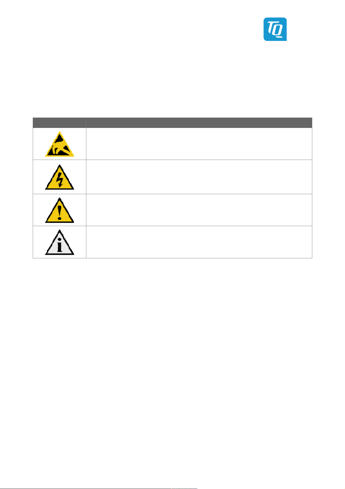
1.2 Symbols and Typographic Conventions
Table 1: Terms and Conventions
Symbol Meaning
This symbol represents the handling of electrostatic-sensitive modules and / or components. These
components are often damaged / destroyed by the transmission of a voltage higher than about 50 V.
A human body usually only experiences electrostatic discharges above approximately 3,000 V.
This symbol indicates the possible use of voltages higher than 24 V.
Please note the relevant statutory regulations in this regard.
Non-compliance with these regulations can lead to serious damage to your health and also cause
damage / destruction of the component.
This symbol indicates a possible source of danger. Acting against the procedure described can lead to
possible damage to your health and / or cause damage / destruction of the material used.
This symbol represents important details or aspects for working with TQ-products.
1.3 Before You Start
This User's Guide must be carefully read and completely understood before you start working with the MBox-R/V.
This User's Guide provides information, which is essential for proper operation of the MBox-R/V. General safety instructions
must be adhered to and only trained and authorized personnel is permitted to work with the MBox-R/V.
1.4 Duty Of Care
It must be ensured that the MBox-R/V is only used in environments, which meet the specification of the MBox-R/V.
The User's Guide has to be completely read and understood and the personnel is authorized and trained regarding standards,
regulations and instructions. It also has to be ensured, that the MBox-R/V is mounted, operated and maintained according
to the instruction of this User's Guide. All applicable national and international regulations and standards have to be obeyed.
1.5 Limited Warranty
Parts which wear out naturally are excluded from the warranty beyond that provided by law.
This applies to e.g., coin cell batteries.
1.6 Liability and Warranty Obligation
TQ-Systems GmbH shall be exempted from the statutory accident liability obligation in case the user does not observe the
information provided in this User's Guide or the warnings on the device. In the event of damage caused by failure to observe
the information provided in this User's Guide or the warnings on the device, TQ-Systems GmbH shall not be required to honour
the warranty even during the warranty period and shall be exempted from the statutory accident liability obligation.
User's Guide l MBox-R/V UG 0103 l © 2017 TQ-Group Page 2
1.7 Safety Guidelines
Use the following safety guidelines to protect your MBox-R/V from potential damage and ensure your personal safety.
If the following safety guidelines are not observed, it could lead to injuries to the operator and/or damage of the MBox-R/V.
In cases of non-observance of the safety guidelines TQ-Systems GmbH is exempt from accident liability, even if the MBox-R/V is
still under warranty. The MBox-R/V must be used as specified in this User's Guide, which describes the safety guidelines for the
MBox-R/V as well as for the operator. The place where the MBox-R/V is installed has to meet the requirements of the country's
standards and regulations. If power cables are delivered with the MBox-R/V only these may be used. Ensure that there is
sufficient air circulation to cool the MBox-R/V. Do not cover the MBox-R/V or mount it close to heat sources or damp places.
To completely disconnect the MBox-R/V from mains, the power cord has to be disconnected. Make sure the power cord is always
easy accessible. Only open the MBox-R/V after all cables are disconnected from the MBox-R/V to insert or remove add-on cards.
This may only be done by qualified personnel. If add-on cards are installed in the MBox-R/V, all effective legal regulations and all
technical data has to be adhered to. It has to be ensured, that the power consumption of add-on cards does not exceed the
limitations and the current consumption specified on the label of the MBox-R/V. Very important! A safe operation is not possible
when the MBox-R/V is visibly damaged or is not functioning at all. In this case the MBox-R/V must be switched off and it must be
ensured that the MBox-R/V cannot be put back into operation. It is very important to ensure that the wires of power cords are
sufficiently dimensioned, according to the maximum electrical specifications of the MBox-R/V. Standards and regulations like
EN62368-1, VDE0100, EN60204, or UL508 have to be adhered to. This information helps you to safely use the MBox-R/V.
Follow and keep all information included with the MBox-R/V. The information in this User's Guide does not alter the terms of
your purchase agreement or the TQ-Systems GmbH Limited Warranty. Your safety is important to us. The MBox-R/V is developed
to be safe and effective. Power cords, power adapters, and other features can create potential safety risks that may result in
physical injury or property damage, especially if misused. To reduce these risks, follow the instructions in this User's Guide, and
observe all warnings on the MBox-R/V and in this User's Guide. By carefully following the information contained in this User's
Guide and provided with the MBox-R/V, you can help protect yourself from hazards and create a safer environment.
Do not attempt to service the MBox-R/V yourself unless instructed to do so by TQ-Systems GmbH or this User's Guide.
1.8 Grounding Considerations
Be aware, that the chassis of the MBox-R/V is internally connected to Digital Ground (Power Supply Connector GND).
Depending on the Power Supply Unit used, it also might be connected or not to protective earth (PE).
This has to be considered, when connecting other components to the MBox-R/V.
The grounding of the MBox-R/V might also influence the electromagnetic emission of the MBox-R/V.
TQ-Systems GmbH recommends using the CINCON TRG70A power supply unit or equivalent, where PE is connected to GND.
1.9 ESD Considerations
To avoid damaging the MBox-R/V caused by ESD make sure the following measures are adhered to:
Ground your workplace with e.g. anti-static mats and ground yourself with a wrist strap. Only use conductive tools when working
on the MBox-R/V. Always handle electrostatic sensitive components at their edges, preferably wear conductive gloves.
Remove the power cord from the MBox-R/V before inserting or removing connectors or before inserting or removing add-on
cards. Don’t touch the contacts of connectors. Keep you work environment tidy and free of non-conductive materials.
1.10 Handling the MBox-R/V
Note: Handling the MBox-R/V
Improper or incorrect handling of the MBox-R/V can substantially reduce its life span. TQ-Systems
GmbH cannot be held responsible for unauthorized modifications made by the user and the
consequences thereof, which may alter the conformity of the MBox-R/V.
1.11 Coin Cell Battery
Note: Coin cell battery
Danger of explosion if the coin cell battery is incorrectly replaced. Replace the coin cell battery only
with a coin cell battery of the same type and size. Check for correct polarity before inserting the coin
cell battery in its socket. Do not immerse into water, heat to more than +100 °C, repair or disassemble
the coin cell battery. Dispose the coin cell battery as required by local ordinances or regulations.

User's Guide l MBox-R/V UG 0103 l © 2017 TQ-Group Page 3
2. ABOUT THIS MANUAL
2.1 Copyright and Licence Expenses
Copyright protected © 2017 by TQ-Systems GmbH.
This User's Guide may not be copied, reproduced, translated, changed or distributed, completely or partially in electronic,
machine readable, or in any other form without the written consent of TQ-Systems GmbH.
The drivers and utilities for the components used as well as the BIOS are subject to the copyrights of the respective
manufacturers. The licence conditions of the respective manufacturer are to be adhered to.
BIOS-licence expenses are paid by TQ-Systems GmbH and are included in the price.
Licence expenses for the operating system and applications are not taken into consideration and must be calculated / declared
separately.
2.2 Registered Trademarks
TQ-Systems GmbH aims to adhere to copyrights of all graphics and texts used in all publications, and strives to use original
or license-free graphics and texts.
All brand names and trademarks mentioned in the publication, including those protected by a third party, unless specified
otherwise in writing, are subjected to the specifications of the current copyright laws and the proprietary laws of the present
registered proprietor without any limitation. One should conclude that brand and trademarks are rightly protected by a third
party.
2.3 Disclaimer
TQ-Systems GmbH does not guarantee that the information in this User's Guide is up-to-date, correct, complete or of good
quality. Nor does TQ-Systems GmbH assume guarantee for further usage of the information.
Liability claims against TQ-Systems GmbH, referring to material or non-material related damages caused, due to usage or
non-usage of the information given in the User's Guide, or due to usage of erroneous or incomplete information, are exempted,
as long as there is no proven intentional or negligent fault of TQ-Systems GmbH. TQ-Systems GmbH explicitly reserves the rights
to change or add to the contents of this User's Guide or parts of it without special notification.
2.4 Imprint
TQ-Systems GmbH
Gut Delling, Mühlstraße 2
D-82229 Seefeld
Tel: +49 8153 9308–0
Fax: +49 8153 9308–4223
Email:
Web:
info@tq-group.com
www.tq-group.com/
2.5 Service, Support, and RMA
Please visit our website www.tq-group.com for latest product documentation, drivers, utilities and technical support.
You can register on our website
For direct technical support you can contact our FAE team
www.tq-group.com to have access to restricted information and automatic update services.
support@tq-group.com.
Our FAE team can also support you with additional information, which is not provided on our website.
For service/RMA, please contact our service team
service@tq-group.com or your TQ sales representative.

User's Guide l MBox-R/V UG 0103 l © 2017 TQ-Group Page 4
3. INTRODUCTION
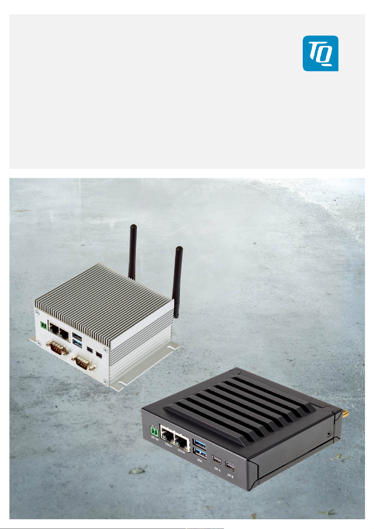
The MBox-R/V is a very compact Embedded PC based on Intel® Atom™ processor series E3800 (Bay Trail-I) for embedded
applications. The highly reliable hardware in combination with the rugged housing design enables the application in industrial
and harsh environmental conditions.
The MBox-R/V focuses to meet individual configurations depending on customers demand. Functionality and interfaces can
easily be added by internal Mini PCIe cards. Typical applications are embedded server and gateway applications, entry level PC
systems for automation, visualisation and monitoring and all applications, which place high demands on quality, durability and
long-term availability.
The name “MBox-R” refers to the MBox with a “robust” housing. The “MBox-R” comes in one height with or without serial ports.
The name “MBox-V” refers to the MBox with a “variable” housing. The “MBox-V” is available in two different heights, with serial
ports (higher housing) or without serial ports (lower housing).
3.1 Functional Overview
The following key functions are implemented in the MBox-R/V:
External Interfaces (standard)
• 2 × Gigabit Ethernet
• 1 × USB 2.0
• 1 × USB 3.0
• 2 × Mini DisplayPort
• Power Button / Reset Button (rear)
Additional Interface according to the individual configuration
• 2 × D-Sub 9-pin (for i.e. RS-232 or other extension interfaces like fieldbus interfaces)
• 2 × SMA connector for antenna
Internal Interfaces and connection possibilities
• Mini PCIe socket (full size, with micro-SIM card support)
• Mini PCIe socket (half size)
• mSATA socket
• MicroSD card socket
• 2 × RS-232 (for internal use or available at the front)
• FAN connector
• Front panel connector
Power Supply
• Input voltage range: 9 to 36 V DC

User's Guide l MBox-R/V UG 0103 l © 2017 TQ-Group Page 5
3.2 MBox-R/V Versions
Currently the MBox-R/V is available in two different configurations. The following table shows the details:
Table 2: MBox-R/V Standard Versions
MBox TQMxE38M DDR3L SDRAM Storage Power Consumption Temp. Range
MBox-R TQMxE38M-AG 4 Gbyte, 1333, ECC 128 Gbyte mSATA 12 W –40 °C to +60 °C
MBox-V TQMxE38M-AE 2 Gbyte, 1066, ECC 16 Gbyte mSATA 8 W –40 °C to +60 °C
The MBox-R/V focuses on individual / customer specific configurations and individual branding.
For this reason several other TQMxE38M modules are available on request:
Table 3: TQMxE38M Module Versions
Module CPU / Graphics TPM DDR3L SDRAM Power consumption Remark
TQMxE38M-AA
"Premium I-Temp."
TQMxE38M-AG
"Premium"
TQMxE38M-AB
"Mainstream"
TQMxE38M-AF
"Mainstream Light"
TQMxE38M-AE
"Light"
TQMxE38M-AC
"Entry-Level"
E3845 Quad Core, 1.91 GHz, 2 Mbyte L2 cache
HD Gfx 542/792 MHz
E3845 Quad Core, 1.91 GHz, 2 Mbyte L2 cache
HD Gfx 542/792 MHz
E3827 Dual Core, 1.75 GHz, 1 Mbyte L2 cache
HD Gfx 542/792 MHz
E3827 Dual Core, 1.75 GHz, 1 Mbyte L2 cache
HD Gfx 542/792 MHz
E3825 Dual Core, 1.33 GHz, 1 Mbyte L2 cache
HD Gfx 533/533 MHz
E3815 Single Core, 1.46 GHz, 512 Kbyte L2 cache
HD Gfx 400/400 MHz
1.2 4 Gbyte, 1333, ECC 10 W –
1.2 4 Gbyte, 1333, ECC 10 W MBox-R
– 4 Gbyte, 1333, ECC 8 W –
– 2 Gbyte, 1333, ECC 8 W –
– 2 Gbyte, 1066, ECC 6 W MBox-V
– 2 Gbyte, 1066, ECC 5 W –
More configuration options are possible:
Mass storage:
• 16 / 32 / 64 / 128 / 256 / 512 Gbyte mSATA (SATA III, MLC) (Standard-Temp. 0 °C to +70 °C)
• 32 / 64 Gbyte mSATA (SATA III, MLC) (Extended-Temp. –40 °C to +85 °C)
• Other mSATA flash drives on request
Add-ons:
• WiFi (Dual Band Wireless AC) with Bluetooth (Standard-Temp. 0 °C to +70 °C)
• WiFi (Single Band) with Bluetooth (Standard-Temp. 0 °C to +70 °C)
• Others on request, e.g.:
o WiFi (Extended-Temp: –40 °C to +85 °C), ZigBee, EnOcean
o Fieldbus interfaces like CAN, ProfiNet, ProfiBus, DeviceNet, ModBus
o Cellular connectivity (2G / 3G / LTE)

User's Guide l MBox-R/V UG 0103 l © 2017 TQ-Group Page 6
4. FUNCTIONAL SPECIFICATION
4.1 Electrical Specification
4.1.1 Supply Voltage Characteristics
The MBox-R/V supports a wide-range voltage input of 9 to 36 V DC.
4.1.2 Power Consumption Specification
The power consumption of the system significantly depends on the configuration and the connected devices (COM Express™
module, mass storage devices, USB devices etc.). The maximum input current of the MBox-R/V is limited to 5 A by a fuse.
The devices connected to the carrier should not exceed 30 W.
Note: Power requirement
The power supply for the MBox-R/V must be configured with enough reserve.
It should be calculated with the maximum power of all connected components.
4.2 Environmental Specification
• Temperature Operating / Extended:
The maximum operating temperature depends on the internal power dissipation which is mainly influenced by the
CPU version. The following temperature parameters were determined by qualification tests (standard configurations
without any add-on cards):
Table 4: CPU Overview
CPU E3845 E3827 E3825 E3815 E3805
CPU Cores 4 2 2 1 2
Cache 2 Mbyte 1 Mbyte 1 Mbyte 512 Kbyte 1 Mbyte
CPU clock 1.91 GHz 1.75 GHz 1.33 GHz 1.46 GHz 1.33 GHz
Temp. T
Memory Speed 1,333 MT/s 1,333 MT/s 1,067 MT/s 1,067 MT/s 1,067 MT/s
Max. memory 8 Gbyte 8 Gbyte 8 Gbyte 8 Gbyte 8 Gbyte
Memory configuration Single, w ECC Single, w ECC Single, w ECC Single, w ECC Single, w ECC
Graphics Intel® HD Graphics Intel® HD Graphics
GFX Base / Burst 542 / 792 MHz 542 / 792 MHz
TDP 10 W 8 W 6 W 5 W 3 W
MBox temp range –40 °C to +60 °C –40 °C to +70 °C
–40 °C to +110 °C –40 °C to +110 °C –40 °C to +110 °C –40 °C to +110 °C –40 °C to +110 °C
junction
Intel® HD Graphics Intel® HD Graphics None
533 / 533 MHz 400 / 400 MHz –
The supported operating temperature range depends on the components and modules used, e.g. if the temperature of the
COM Express™ module is in the range of 0 °C to +60 °C, the maximum operating temperature range is 0 °C to +60 °C.
• Storage temperature: –40 °C to +85 °C
• Relative humidity (operating / storage): 10 % to 90 % (not condensing)
Note: Environmental conditions
When powering the MBox-R/V, make sure the chassis is not covered by any objects.
Otherwise the heat dissipation will be restricted by physical effects and the maximum operating
temperature will be reduced.

User's Guide l MBox-R/V UG 0103 l © 2017 TQ-Group Page 7
2 × Ethernet
USB 3.0
Mini DisplayPort
s USB
2.0 DC-IN
2 × Ethernet
USB 3.0
Mini DisplayPort
s USB 2.0
DC-IN
D-Sub-9 (i.e. RS
-
232 or Fieldbus interfaces)
4.3 Connectors and Interfaces
4.3.1 External Connectors and Interfaces Arrangement
9 to 36 V
Illustration 1: MBox-R, Front with D-Sub-9 Connectors
9 to 36 V
Illustration 2: MBox-V, Front without D-Sub-9 Connectors
User's Guide l MBox-R/V UG 0103 l © 2017 TQ-Group Page 8
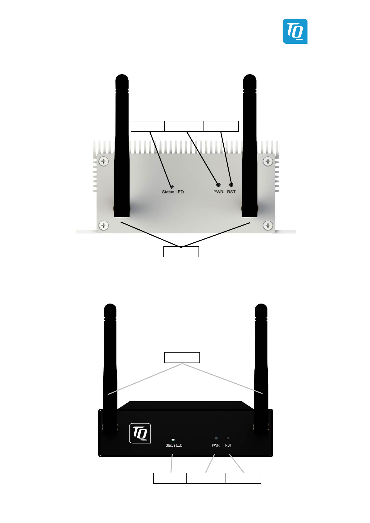
Antennas
Status LED
Power Button
Reset Button
Antennas
Status LED
Power Button
Reset Button
Illustration 3: MBox-R, Rear
Illustration 4: MBox-V, Rear

User's Guide l MBox-R/V UG 0103 l © 2017 TQ-Group Page 9
4.3.1.1 Power Supply Connector
The MBox-R/V supports a wide-range voltage input from 9 to 36 V DC.
Power-In connector:
• Connector type: Phoenix MC1,5/2-G-3,5
• Mating connector: e.g. Phoenix FMC1,5/2-ST-3,5
Table 5: Pinout Power-In Connector
Pin Signal Remark
1 (+) 9 to 36 V Fused @ 5 A
2 (–) GND / chassis –
Illustration 5: DC Power Supply Connector
Note: Power requirement
Do not connect or disconnect the Power Supply to the MBox-R/V under voltage.
Switch off the voltage before plugging.
4.3.1.2 Mini DisplayPort
The MBox-R/V supports two mini DisplayPort interfaces.
The interfaces support DP++ signalling. Therefore it is possible
to connect monitors with DP, DVI, HDMI and VGA input by using
dedicated cables and adapters.
The actual configuration with the Intel Atom E3800 series has
extended monitor support with resolutions
up to 2 × 2560 × 1600.
Illustration 6: Mini DP Connector
4.3.1.3 USB Host Interfaces
The MBox-R/V supports two USB Host interfaces.
Double A-Type USB connector for direct usage of USB host ports
• Top USB Port (USB 3.0)
• Bottom USB Port (USB 2.0)
The maximum cable length of the USB interface is 3 m.
4.3.1.4 Gigabit Ethernet
The MBox-R/V supports two common Gigabit Ethernet ports. An Intel® i210IT Ethernet controller with 10/100/1000 Mbps speed
is implemented on both Ports.
Table 6: Ethernet LEDs
LED Colour / Status Remark
Left (Link) Off No link
Left (Link) Green Link connected
Right (ACT) Off No activity
Right (ACT) Yellow Activity
Illustration 7: RJ45 Connectors

User's Guide l MBox-R/V UG 0103 l © 2017 TQ-Group Page 10
4.3.1.5 Status LED
The MBox-R/V is equipped with a Status LED (on rear side).
Table 7: Status LED Conditions
Status LED LED Colour Description
Off – S5 State (System is shut down or not powered)
On Green S0 State (System is running)
On Orange S3 State (System is in Sleep mode)
4.3.1.6 Power Button and Reset Button
The Power Button and the Reset Button on the rear side of the MBox-R/V provide the following functions.
Table 8: Power Button and Reset Button Functions
Status Event System response
No power supply connected Power is supplied System starts automatically (BIOS default: S0)
System is shut down or in sleep mode (S3, S5) Power button pushed <4 s System starts (S0)
System running (S0) Power button pushed <4 s
System shuts down or turns into sleep mode
(S3, S5 depending on Windows settings)
System running (S0) Power button pushed >4 s System shuts down (S5)
System running (S0) Reset button pushed System restarts (S0)

User's Guide l MBox-R/V UG 0103 l © 2017 TQ-Group Page 11
4.3.2 Optional External Connectors and Interfaces Arrangement
4.3.2.1 Serial Interfaces RS-232
The MBox-R/V provides up to two serial ports:
• 2 × D-Sub-9 RS-232 port (4-wire)
• Legacy compatible (IO addresses and IRQs)
• Up to 115 kbaud
To connect the internal RS-232 connectors to the front panel, the following adapters is used.
• Adapter cable 150 mm from internal connector to a 9-pin D-Sub connector, order code: 278622.0100
Illustration 8: D-Sub-9 Adapter Cable
Table 9: RS-232 D-Sub-9 Connector
Pin D-Sub-9 Connector
1 –
2 RXD
3 TXD
4 –
5 GND
6 –
7 RTS
8 CTS
9 –
10 –
Illustration 9: RS-232 D-Sub-9 Connector
If the D-Sub-9 connectors at the front are used for other interfaces (like fieldbus), the RS-232 interfaces are not available.
4.3.2.2 SMA Antenna Connectors
In combination with a Wireless or Bluetooth Mini PCI Express card, it is possible to add SMA antenna connectors for external
antennas. For options and more information refer to chapter 3.2 and 4.3.2.5.
4.3.2.3 Other Optional Connectors
For individual solutions more optional connectors are available.
4.3.2.4 mSATA Interface for Mass Storage
An SSD is plugged in the mSATA socket on the carrier board of the MBox-R/V.
The size can be chosen according the requirements. See “mass storage” in chapter 3.2.
4.3.2.5 Mini PCIe Extension Sockets
The MBox-R/V provides up to two Mini PCIe card slots to extend the IOs or other system functionality.
One Mini PCIe slot also provides a micro-SIM card socket. The socket is accessible when the back panel is removed.
• One full-size socket (for 50.95 mm × 30 mm Mini PCIe cards)
o Supports PCIe ×1 and USB 2.0
o Micro-SIM card socket on carrier board in the MBox-R/V (SIM/USIM card for 2G/3G/LTE modem support)
• One half-size socket (for 26.8 mm × 30 mm Mini PCIe cards)
o Supports PCIe ×1 and USB 2.0
4.3.2.6 MicroSD Card Socket
The carrier board in the MBox-R/V provides a microSD card socket. The socket is accessible when the back panel is removed.

User's Guide l MBox-R/V UG 0103 l © 2017 TQ-Group Page 12
5. MECHANICS
5.1 Dimensions
The following illustrations show the MBox-R
Illustration 10: MBox-R, Dimensions (mm), Front View
Illustration 11: MBox-R, Dimensions (mm), Side View

User's Guide l MBox-R/V UG 0103 l © 2017 TQ-Group Page 13
The full height of the housing
incl. cooling fins is 40 mm.
Illustration 12: MBox-V (without D-Sub-9 Connectors), Dimensions (mm), Bottom View
Illustration 13: MBox-V (with D-Sub-9 Connectors), Dimensions (mm), Bottom View
The full height of the housing
incl. cooling fins is 55 mm.

User's Guide l MBox-R/V UG 0103 l © 2017 TQ-Group Page 14
5.2 Mounting
There are several possibilities to mount the MBox-R/V:
• With an adapter plate
• To a cap rail with a clamp
• Directly with screws
Please contact
support@tq-group.com for more details or ideas suitable for your application.
The mounting slots
are 4.5 mm wide.
Illustration 14: MBox-R, Mounting Dimensions (mm), Top View
Four mounting holes M 3
Two DIN rail
mounting holes M 4
Illustration 15: MBox-V, Dimensions of Mounting Holes (mm), Bottom View

User's Guide l MBox-R/V UG 0103 l © 2017 TQ-Group Page 15
6. REGULATORY INFORMATION
6.1 EU Compliance with Electromagnetic Compatibility Directive
The MBox-R/V is in conformity with the protection requirements of EU Council Directive 2014/30/EU on the approximation
of the laws of the Member States relating to electromagnetic compatibility. TQ-Systems GmbH cannot accept responsibility
for any failure to satisfy the protection requirements resulting from a non-recommended modification of the MBox-R/V,
including the installation of option cards from other manufacturers.
The MBox-R/V has been tested and found to comply with the limits for Class B Information Technology Equipment according to
European Standard EN 55022, using the CINCON TRG70A power supply unit where PE is connected to GND. The limits for Class B
equipment were derived for typical residential environments to provide reasonable protection against interference with licensed
communication devices.
6.2 Declaration of Conformity
We hereby declare under our sole responsibility that the
MBOX-V-E3825, Mat. No.: 292536
complies with the essential requirements, which are laid down in the referred harmonization directives below:
• Directive 2011/65/EU of the European Parliament and of the council from June 8, 2011
• Directive 2014/30/EU of the European Parliament and of the council from February 26, 2014
• Directive 2012/19/EU of the European Parliament and of the council from July 4, 2012
The MBOX-V-E3825, Mat. No.: 292536also complies with the appropriate harmonised directives or specifications:
• EN 50581, 2012-09
• EN 55022, 2010 / AC:2011
• EN 55024, 2010 + A1:2015
Additional information:
This declaration of Conformity is valid for all units, which are produced according to manufacturing drawings, which are a part of
the technical documentation. Further information with respect to compliance with the standards and directives mentioned
before, can be found in the accompanying documentation.
Signed for / on behalf of: TQ-Systems GmbH
Name, first name: i.V. Fromberger, Josef
Function: Head of Embedded Division
____________________________ _________________________________
Place and date Signature

User's Guide l MBox-R/V UG 0103 l © 2017 TQ-Group Page 16
7. WEEE AND RECYCLING
7.1 WEEE
TQ-Systems GmbH encourages owners to recycle their MBox-R/V when it is not needed anymore.
The Waste Electrical and Electronic Equipment (WEEE) mark only applies to countries within the European Union (EU) and
Norway. Appliances are labelled in accordance with European Directive 2012/19/EU concerning waste electrical and electronic
equipment (WEEE). The Directive determines the framework for the return and recycling of used appliances as applicable
throughout the European Union.
7.2 Recycling
Users of the MBox-R/V must not dispose the MBox-R/V as unsorted municipal waste, but use the
collection framework available in their country for the return, recycle, or recovery of WEEE and
minimize any potential effects on the environment and human health due to the presence of
hazardous substances.
8. APPENDIX
Table 10: Further Applicable Software, Drivers and Documents
No. Name Rev. / Date Company
Intel® Atom™ processor E3800 Product Family: Software and Drivers download
(1)
www.intel.com/content/www/us/en/embedded/products/bay-trail/software-and-drivers.html
Intel® Download Center: Intel® Ethernet Controller i210 Series
(2)
https://downloadcenter.intel.com/product/64399/Intel-Ethernet-Controller-I210-Series
–
–
Intel®
Intel®

TQ-Systems GmbH
Mühlstraße 2 l Gut Delling l 82229 Seefeld
info@tq-group.com l www.tq-group.com
 Loading...