

User's Manual l MB-M10-1 UM 0100 l © 2016 TQ-Group Page 1
MB
-
M10
-1
User's Manual
MB-M10-1 UM 0100
2016-04-01


User's Manual l MB-M10-1 UM 0100 l © 2016 TQ-Group Page i
TABLE OF CONTENTS
1. ABOUT THIS MANUAL................................................................................................................................................................................1
1.1 Copyright and Licence Expenses ...........................................................................................................................................................1
1.2 Registered Trademarks.............................................................................................................................................................................. 1
1.3 Disclaimer......................................................................................................................................................................................................1
1.4 Imprint............................................................................................................................................................................................................ 1
1.5 Service and Support...................................................................................................................................................................................1
1.6 Tips on Safety ...............................................................................................................................................................................................2
1.7 Symbols and Typographic Conventions.............................................................................................................................................. 2
1.8 Handling and ESD Tips ..............................................................................................................................................................................2
1.9 Naming of Signals.......................................................................................................................................................................................3
1.10 Further Applicable Documents / Presumed Knowledge................................................................................................................3
2. INTRODUCTION ...........................................................................................................................................................................................4
2.1 Functional Overview..................................................................................................................................................................................4
2.2 Specification Compliance......................................................................................................................................................................... 4
2.3 Versions..........................................................................................................................................................................................................4
2.4 Accessories....................................................................................................................................................................................................5
3. FUNCTIONAL SPECIFICATION..................................................................................................................................................................6
3.1 Block Diagram..............................................................................................................................................................................................6
3.2 Electrical Specification...............................................................................................................................................................................6
3.2.1 Supply Voltage Characteristics ............................................................................................................................................................... 6
3.2.2 Power Consumption Specification........................................................................................................................................................6
3.3 Environmental Specification ...................................................................................................................................................................6
3.4 System Components..................................................................................................................................................................................7
3.4.1 Gigabit Ethernet Controller......................................................................................................................................................................7
3.5 Connectors and Interfaces .......................................................................................................................................................................7
3.5.1 Power Supply ...............................................................................................................................................................................................9
3.5.2 Mini DisplayPort ..........................................................................................................................................................................................9
3.5.3 USB Host / Device Interfaces ...................................................................................................................................................................9
3.5.4 Gigabit Ethernet ....................................................................................................................................................................................... 10
3.5.5 Serial Interfaces (RS232/RS422) ........................................................................................................................................................... 10
3.5.6 Mini PCIe Socket....................................................................................................................................................................................... 11
3.5.7 mSATA Interfaces..................................................................................................................................................................................... 11
3.5.8 Micro SD Card Socket.............................................................................................................................................................................. 11
3.5.9 Fan Connector........................................................................................................................................................................................... 11
3.5.10 Front Panel Connector ........................................................................................................................................................................... 11
3.5.11 State LED..................................................................................................................................................................................................... 12
3.5.12 COM Express™ Connector ..................................................................................................................................................................... 12
4. MECHANICS ............................................................................................................................................................................................... 13
4.1 Dimensions ................................................................................................................................................................................................ 13
4.2 Hardware Kit Assembly .......................................................................................................................................................................... 14
4.3 Protection Against External Effects .................................................................................................................................................... 14
5. SOFTWARE.................................................................................................................................................................................................. 15
5.1 Operating Systems .................................................................................................................................................................................. 15
5.1.1 Supported Operating Systems............................................................................................................................................................. 15
5.1.2 Driver Download...................................................................................................................................................................................... 15
6. SAFETY REQUIREMENTS AND PROTECTIVE REGULATIONS......................................................................................................... 16
6.1 EMC............................................................................................................................................................................................................... 16
6.2 ESD................................................................................................................................................................................................................ 16
6.3 Operational Safety and Personal Security........................................................................................................................................ 16
6.4 Reliability and Service Life..................................................................................................................................................................... 16
6.4.1 RoHS Compliance..................................................................................................................................................................................... 16
6.4.2 WEEE Regulation ...................................................................................................................................................................................... 16
6.5 Other Entries.............................................................................................................................................................................................. 16
7. APPENDIX ................................................................................................................................................................................................... 17
7.1 Acronyms and Definitions..................................................................................................................................................................... 17
7.2 References.................................................................................................................................................................................................. 19

User's Manual l MB-M10-1 UM 0100 l © 2016 TQ-Group Page ii
TABLE DIRECTORY
Table 1: Terms and Conventions.....................................................................................................................................................................2
Table 2: Pinout Power-In Connector X1........................................................................................................................................................9
Table 3: Pinout mini DP Connectors X4, X5................................................................................................................................................. 9
Table 4: Ethernet LEDs..................................................................................................................................................................................... 10
Table 5: Serial Port COM Express™ Port Mapping................................................................................................................................... 10
Table 6: RS232 Connector X11...................................................................................................................................................................... 10
Table 7: 5 V Fan Connector X17.................................................................................................................................................................... 11
Table 8: Front Panel Connector X10 ........................................................................................................................................................... 11
Table 9: State LED Conditions....................................................................................................................................................................... 12
Table 10: Acronyms ............................................................................................................................................................................................ 17
Table 11: Further Applicable Documents and Links................................................................................................................................. 19
ILLUSTRATION DIRECTORY
Illustration 1: D-Sub-9 Adapter Cable......................................................................................................................................................................5
Illustration 2: Block Diagram MB-M10-1 .................................................................................................................................................................6
Illustration 3: MB-M10-1, Top .....................................................................................................................................................................................7
Illustration 4: MB-M10-1, Bottom..............................................................................................................................................................................8
Illustration 5: mini DP Connectors X4, X5............................................................................................................................................................... 9
Illustration 6: Double RJ45 Connector X2............................................................................................................................................................ 10
Illustration 7: RS232 Connector X11...................................................................................................................................................................... 10
Illustration 8: D-Sub-9 Connector .......................................................................................................................................................................... 10
Illustration 9: 5 V Fan Connector X17.................................................................................................................................................................... 11
Illustration 10: Front Panel Connector X10 ........................................................................................................................................................... 11
Illustration 11: MB-M10-1, Dimensions................................................................................................................................................................... 13
Illustration 12: MB-M10-1, 3D View, Assembly..................................................................................................................................................... 14
REVISION HISTORY
Rev. Date Name Pos. Modification
0100 2016-04-01 FP First edition

User's Manual l MB-M10-1 UM 0100 l © 2016 TQ-Group Page 1
1. ABOUT THIS MANUAL
1.1 Copyright and Licence Expenses
Copyright protected © 2016 by TQ-Systems GmbH.
This User's Manual may not be copied, reproduced, translated, changed or distributed, completely or partially
in electronic, machine readable, or in any other form without the written consent of TQ-Systems GmbH.
The drivers and utilities for the components used as well as the BIOS are subject to the copyrights of the respective
manufacturers. The licence conditions of the respective manufacturer are to be adhered to.
BIOS-licence expenses are paid by TQ-Systems GmbH and are included in the price.
Licence expenses for the operating system and applications are not taken into consideration and must be separately
calculated / declared.
1.2 Registered Trademarks
TQ-Systems GmbH aims to adhere to the copyrights of all the graphics and texts used in all publications, and strives to use
original or license-free graphics and texts.
All the brand names and trademarks mentioned in the publication, including those protected by a third party, unless specified
otherwise in writing, are subjected to the specifications of the current copyright laws and the proprietary laws of the present
registered proprietor without any limitation. One should conclude that brand and trademarks are rightly protected by a third
party.
1.3 Disclaimer
TQ-Systems GmbH does not guarantee that the information in this User's Manual is up-to-date, correct, complete or of good
quality. Nor does TQ-Systems GmbH assume guarantee for further usage of the information. Liability claims against TQ-Systems
GmbH, referring to material or non-material related damages caused, due to usage or non-usage of the information given in the
User's Manual, or due to usage of erroneous or incomplete information, are exempted, as long as there is no proven intentional
or negligent fault of TQ-Systems GmbH.
TQ-Systems GmbH explicitly reserves the rights to change or add to the contents of this User's Manual or parts of it without
special notification.
1.4 Imprint
TQ-Systems GmbH
Gut Delling, Mühlstraße 2
D-82229 Seefeld
Tel: +49 (0) 8153 9308–0
Fax: +49 (0) 8153 4223
Email:
info@tq-group.com
Web:
http://www.tq-group.com/
1.5 Service and Support
Please visit our website www.tq-group.com for latest product documentation, drivers, utilities and technical support.
You can register on our website
www.tq-group.com to have access to restricted information and automatic update services.
For direct technical support you can contact our FAE team by email:
support@tq-group.com.
Our FAE team can also support you with additional information like 3D-STEP files and confidential information, which is not
provided on our public website.
For service/RMA, please contact our service team by email (
service@tq-group.com) or your sales team at TQ.
User's Manual l MB-M10-1 UM 0100 l © 2016 TQ-Group Page 2
1.6 Tips on Safety
Improper or incorrect handling of the product can substantially reduce its life span.
1.7 Symbols and Typographic Conventions
Table 1: Terms and Conventions
Symbol Meaning
This symbol represents the handling of electrostatic-sensitive modules and / or components. These
components are often damaged / destroyed by the transmission of a voltage higher than about 50 V.
A human body usually only experiences electrostatic discharges above approximately 3,000 V.
This symbol indicates the possible use of voltages higher than 24 V.
Please note the relevant statutory regulations in this regard.
Non-compliance with these regulations can lead to serious damage to your health and also cause
damage / destruction of the component.
This symbol indicates a possible source of danger. Acting against the procedure described can lead to
possible damage to your health and / or cause damage / destruction of the material used.
This symbol represents important details or aspects for working with TQ-products.
Command
A font with fixed-width is used to denote commands, contents, file names, or menu items.
1.8 Handling and ESD Tips
General handling of your TQ-products
The TQ-product may only be used and serviced by certified personnel who have taken note of the
information, the safety regulations in this document and all related rules and regulations.
A general rule is: do not touch the TQ-product during operation. This is especially important when
switching on, changing jumper settings or connecting other devices without ensuring beforehand
that the power supply of the system has been switched off.
Violation of this guideline may result in damage / destruction of the MB-M10-1 module and be
dangerous to your health.
Improper handling of your TQ-product would render the guarantee invalid.
Proper ESD handling
The electronic components of your TQ-product are sensitive to electrostatic discharge (ESD).
Always wear antistatic clothing, use ESD-safe tools, packing materials etc., and operate your TQ-
product in an ESD-safe environment. Especially when you switch modules on, change jumper settings,
or connect other devices.

User's Manual l MB-M10-1 UM 0100 l © 2016 TQ-Group Page 3
1.9 Naming of Signals
A hash mark (#) at the end of the signal name indicates a low-active signal.
Example: RESET#
If a signal can switch between two functions and if this is noted in the name of the signal, the low-active function is marked with
a hash mark and shown at the end.
Example: C / D#
If a signal has multiple functions, the individual functions are separated by slashes when they are important for the wiring.
The identification of the individual functions follows the above conventions.
Example: WE2# / OE#
1.10 Further Applicable Documents / Presumed Knowledge
• Specifications and manual of the modules used:
These documents describe the service, functionality and special characteristics of the module used.
• Specifications of the components used:
The manufacturer's specifications of the components used, for example CompactFlash cards, are to be taken note of.
They contain, if applicable, additional information that must be taken note of for safe and reliable operation.
These documents are stored at TQ-Systems GmbH.
• Chip errata:
It is the user's responsibility to make sure all errata published by the manufacturer of each component are taken note of.
The manufacturer’s advice should be followed.
• Software behaviour:
No warranty can be given, nor responsibility taken for any unexpected software behaviour due to deficient components.
• General expertise:
Expertise in electrical engineering / computer engineering is required for the installation and the use of the device.
Implementation information for the carrier board design is provided in the COM Express™ Design Guide (2) maintained by the
PICMG®. This Carrier Design Guide includes a very good guideline to design a COM Express™ carrier board.
It includes detailed information with schematics and detailed layout guidelines.
Please refer to the official PICMG® documentation for additional information (1), (2).

User's Manual l MB-M10-1 UM 0100 l © 2016 TQ-Group Page 4
2. INTRODUCTION
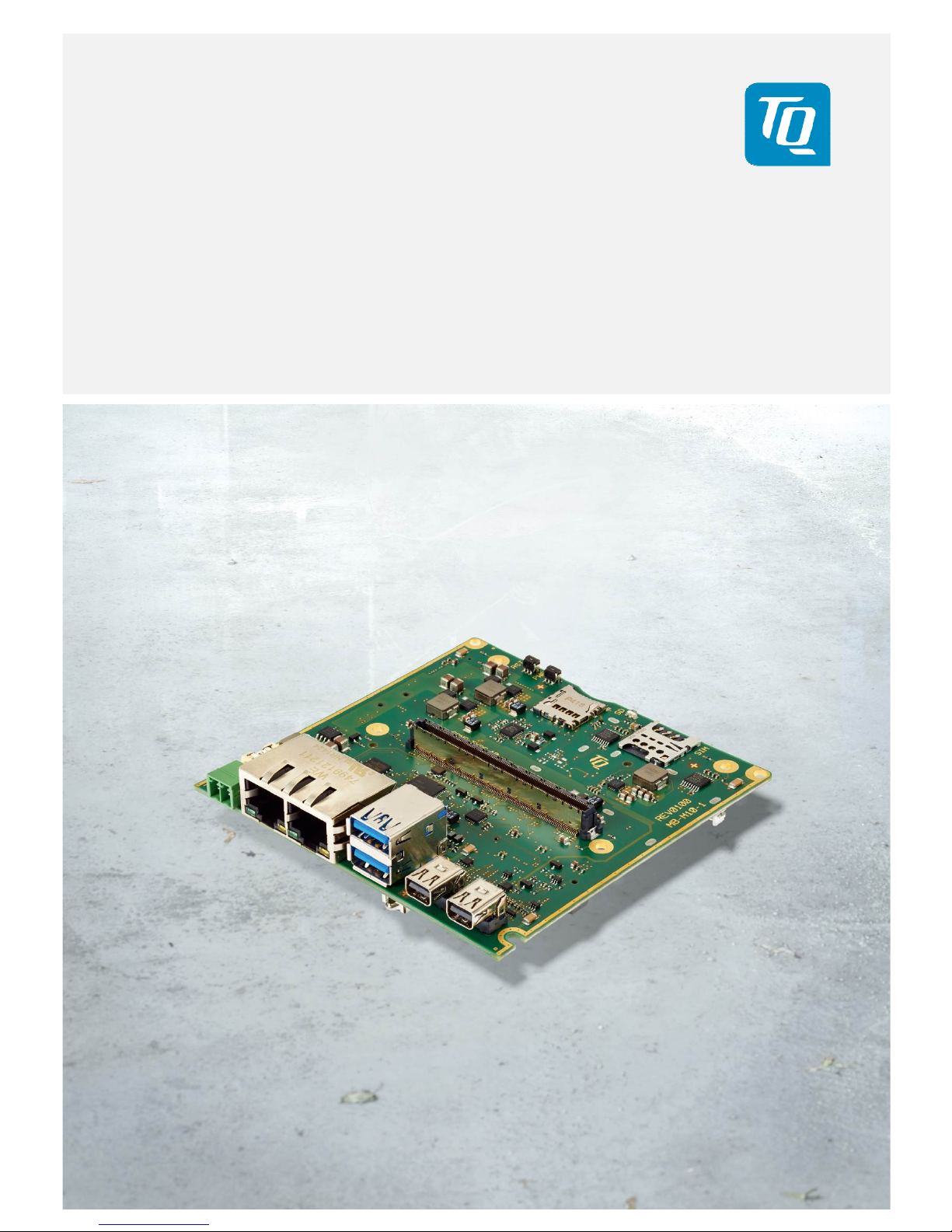
The mainboard MB-M10-1 in combination with a CPU module based on PICMG standard COM Express™ Mini Type 10
(COM.0 R2.1) forms an extremely compact and powerful embedded PC platform.
The modularity enables future-proof designs with latest Intel® Atom™ embedded CPUs.
High speed communication interfaces and powerful graphics capabilities with up to dual 2560 × 1600 resolution enables
smart gateway, BoxPC and digital signage applications.
The compact (100 × 100 mm) and robust design, the optional extended temperature range as well as the option of
conformal coating extends the use cases to applications within rugged industry, railway and outdoor / harsh environment.
Based on the very low power consumption and smart power management the applications can be realized with passive cooling
(fanless).
2.1 Functional Overview
The following key functions are implemented on the MB-M10-1:
Supported Modules:
• COM Express™ Mini Modules with Type 10 pinout
External Interfaces:
• 2 × Gigabit Ethernet
• 2 × USB3.0
• 2 × mini DisplayPort
• Power Button / Reset
Internal Interfaces:
• Mini PCIe socket (with micro-SIM card support)
• Mini PCIe socket (half size)
• mSATA socket
• micro SD card socket
• 2 × RS232
• FAN connector
• Front panel connector
Power supply:
• Input Voltage Range: 9 V to 36 V DC
Environment:
• Extended Temperature: –40 °C to +85 °C
1
Form factor / dimensions:
• 100 mm × 100 mm
• Suitable for 100 mm standard chassis
• Also suitable for embedded NUC standard chassis (eNUC compatible mounting points and IO shield)
2.2 Specification Compliance
The MB-M10-1 supports modules compliant to the PICMG™ COM Express™ Module Base Specification (COM.0 R2.1) with
Type 10 pinout.
2.3 Versions
The MB-M10-1 carrier is available in the following configurations:
• MB-M10-1-AA (“Standard”)
• Customer-specific configurations on request
1: Exclusive battery (Standard CR2032 battery is specified for –20 °C to +60 °C).

User's Manual l MB-M10-1 UM 0100 l © 2016 TQ-Group Page 5
2.4 Accessories
The D-Sub-9 adapter cable “DK-RS232-9POL-DSUB-PICOBLADE REV.0100” has the order code 278622.0100.
It is 130 mm long and connects the internal connector X11 with a 9-pin D-Sub connector.
Illustration 1: D-Sub-9 Adapter Cable
Please contact
support@tq-group.com for more details about mini Display Port cables and
mini Display Port to DVI/HDMI adapters.

User's Manual l MB-M10-1 UM 0100 l © 2016 TQ-Group Page 6
3. FUNCTIONAL SPECIFICATION
3.1 Block Diagram
The following illustration shows the block diagram of the MB-M10-1:
Illustration 2: Block Diagram MB-M10-1
3.2 Electrical Specification
3.2.1 Supply Voltage Characteristics
The MB-M10-1 supports a wide-range voltage input from 9 to 36 V DC.
3.2.2 Power Consumption Specification
The power consumption of the system significantly depends on the connected devices
(COM Express™ module, Mass storage devices, USB devices etc.).
The power consumption of the MB-M10-1 itself is approximately 50 mA @ 12 V (COM Express™ module supplied externally;
UEFI-shell active; no keyboard, no mouse, no mass storage device, no Ethernet cable etc. connected).
The maximum input current of the MB-M10-1 is limited to 5 A by a fuse.
The devices connected to the carrier should not exceed 30 W.
Note: Power requirement
The power supply for the MB-M10-1 must be configured with enough reserve.
It should be calculated with the maximum power of all connected components.
3.3 Environmental Specification
• Temperature operating, Extended: –40 °C to +85 °C
2
• Temperature storage: –40 °C to +85 °C
2
• Relative humidity (operating / storage): 10 % to 90 % (not condensing)
2: Exclusive battery (Standard CR2032 battery is specified for –20 °C to +60 °C).

User's Manual l MB-M10-1 UM 0100 l © 2016 TQ-Group Page 7
3.4 System Components
3.4.1 Gigabit Ethernet Controller
The MB-M10-1 is equipped with an Intel® i210IT Ethernet controller with 10/100/1000 Mbps speed and IEEE1588 support.
Please contact
support@tq-group.com for further information about the IEEE1588 support.
3.5 Connectors and Interfaces
Illustration 3: MB-M10-1, Top
Reset
Button
X7:
micro-SIM
card socket
State
LED
X6: micro
SD card socket
X8: COM Express™
connector
X1: Power In
9 to 36
V DC
Power
Button
+ | -
X2:
Gigabit
Ethernet
X3:
2 × USB 3.0
X4:
mini
Display
Port
X5:
mini
Display
Port

User's Manual l MB-M10-1 UM 0100 l © 2016 TQ-Group Page 8
Illustration 4: MB-M10-1, Bottom
X9: Serial 0
RS232
X12:
mSATA socket
X16: Mini PCIe
socket
X17: FAN
connector
X10: Front panel
connector
X11: Serial 1
RS232
X15: Mini PCIe
socket (half size)
User's Manual l MB-M10-1 UM 0100 l © 2016 TQ-Group Page 9
3.5.1 Power Supply
The MB-M10-1 supports a wide-range voltage input from 9 to 36 V DC.
X1: Power-In Connector
• Connector type: Phoenix MC1,5/2-G-3,5
• Mating connector: e.g. Phoenix FMC1,5/2-ST-3,5
Table 2: Pinout Power-In Connector X1
Pin Signal Remark
1 9 to 36 V Fused @ 5 A
2 GND
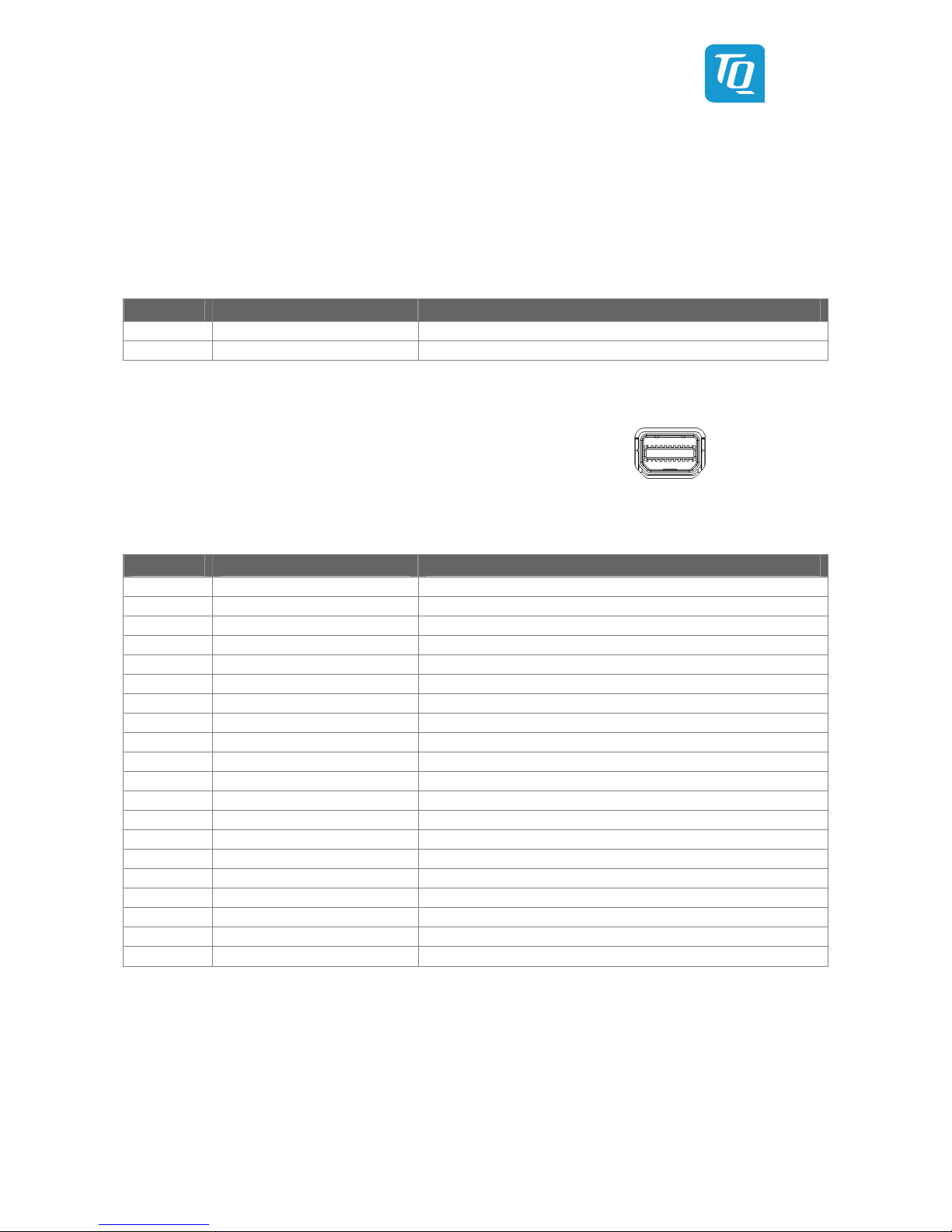
3.5.2 Mini DisplayPort
The MB-M10-1 supports two mini DisplayPort interfaces. The support of
adapters from mini DP to HDMI, DVI or VGA depends on the combination
of the COM Express™ module and the adapter used. The combination of
some modules with some adapters might not work.
Illustration 5: mini DP Connectors X4, X5
Table 3: Pinout mini DP Connectors X4, X5
Pin Signal Remark
1 GND
2 HPD Hot plug detect
3 Lane 0+
4 CONFIG1
5 Lane 0–
6 CONFIG2
7 GND
8 GND
9 Lane 1+
10 Lane 3+
11 Lane 1–
12 Lane 3–
13 GND
14 GND
15 Lane 2+
16 AUX_CH+
17 Lane 2–
18 AUX_CH–
19 GND
20 DP_PWR
3.5.3 USB Host / Device Interfaces
The MB-M10-1 provides two USB Hosts interfaces at X3, a double A-Type (USB3.0) connector for direct usage of USB host ports.
User's Manual l MB-M10-1 UM 0100 l © 2016 TQ-Group Page 10
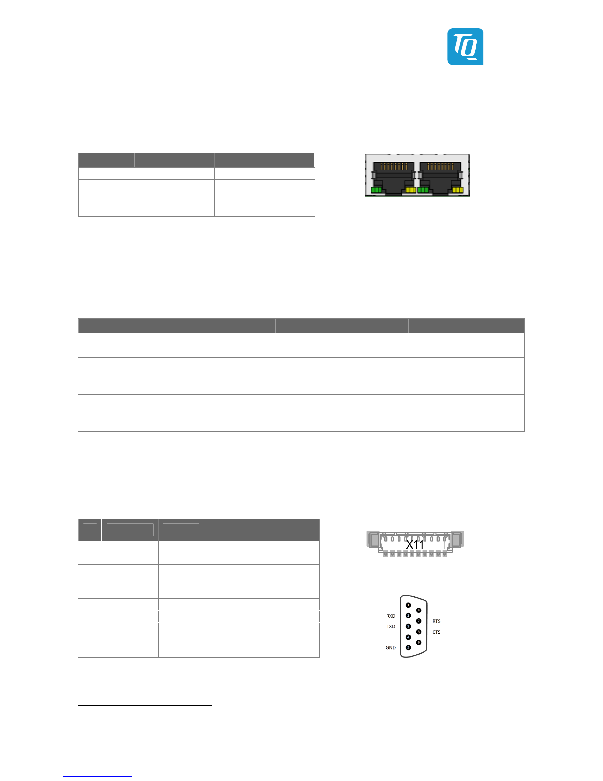
3.5.4 Gigabit Ethernet
The MB-M10-1 supports two Gigabit Ethernet ports. The Ethernet signals of the COM Express™ connector are routed to X2.
The right port of X2 on the MB-M10-1 is connected to an Intel® i210IT Ethernet controller with 10/100/1000 Mbps speed.
Table 4: Ethernet LEDs
Illustration 6: Double RJ45 Connector X2
3.5.5 Serial Interfaces (RS232/RS422)
The MB-M10-1 provides two RS232 ports at on-board headers.
The COM Express™ Specification only supports RX and TX lines of the serial interface. Due to the TQ-flexiCFG feature the serial
ports can be configured to route the handshake signals to free pins on the COM Express™ connector.
Table 5: Serial Port COM Express™ Port Mapping
COM Express™ Signal COM Express™ Pin MB-M10-1 Remark
SER0_TX A98 SER0_TX 3.3 V input
SER0_RX A99 SER0_RX 3.3 V output
SER1_TX A101 SER1_TX 3.3 V input
SER1_RX A102 SER1_RX 3.3 V output
SER0_RTS# 3 B77 SER0_RTS# 3.3 V input
SER0_CTS# 3 B78 SER0_CTS# 3.3 V output
SER1_RTS# 3 A78 SER1_RTS# 3.3 V input
SER1_CTS# 3 A79 SER1_CTS# 3.3 V output
The four COM Express™ serial signals (RX/TX) are specified to provide protection and level shifter circuitry.
To implement this circuitry would lead to lower transfer speeds of the two serial ports on the COM Express™ module.
There is no protective circuitry on the MB-M10-1 and therefore the serial ports provide transfer rates of up to 115 kbaud.
The MB-M10-1 can only be used in combination with COM Express™ modules Type 10 pinout.
Table 6: RS232 Connector X11
Illustration 7: RS232 Connector X11
Illustration 8: D-Sub-9 Connector
3: These signals are not specified in COM Express™ specification.
These signals are only available when the TQ flexiCFG feature is available on the COM Express™ module. TQMxE38M modules support this feature.
4: Not available since signal is not defined in COM Express™ specification.
5: Only available when the TQ flexiCFG feature is available on the COM Express™ module.
LED Colour/ State Description
Left (Link) Off No link
Left (Link) Green Link connected
Right (ACT) Off No activity
Right (ACT) Yellow Activity
Pin RS232 Signals MB-M10-1
D-Sub connector
(with D-Sub adapter, see page 5)
1 DCD NC 4 –
2 DSR
NC 4
RXD
3 RXD RXD TXD
4 RTS RTS 5 –
5 TXD TXD GND
6 CTS
CTS 5
–
7 DTR
NC 4
RTS
8 RI
NC 4
CTS
9 GND GND –
10 – NC –

User's Manual l MB-M10-1 UM 0100 l © 2016 TQ-Group Page 11
3.5.6 Mini PCIe Socket
The MB-M10-1 supports up to two Mini PCIe cards to extend the functionality of the system.
• One full-size socket (for 50.95 mm × 30 mm Mini PCIe cards)
o Supports PCIe ×1 and USB 2.0
o Micro-SIM card socket on MB-M10-1 for SIM/USIM card for 2G/3G/LTE modem support
• One half-size socket (for 26.8 mm × 30 mm Mini PCIe cards)
o Supports PCIe ×1 and USB 2.0
The maximum transfer rates of these interfaces mainly depend on the COM Express™ module used and the connected devices.
3.5.7 mSATA Interfaces
The MB-M10-1 supports an mSATA interface:
• One mSATA socket for mSATA-SSD
The maximum transfer rate of this interface mainly depends on the COM Express™ module used and the connected device.
3.5.8 Micro SD Card Socket
The MB-M10-1 provides a socket for micro SD cards.
The SDIO signals on COM Express™ modules can also be used as GPIO signals.
Please ensure that the module is configured for SDIO-usage of these pins.
3.5.9 Fan Connector
The MB-M10-1 provides a fan connector.
X17: 5 V fan connector
• Connector type: Molex 53398-0371
• Mating connector: e.g. Molex 51021-0300 crimp housing
Table 7: 5 V Fan Connector X17
Illustration 9: 5 V Fan Connector X17
3.5.10 Front Panel Connector
The MB-M10-1 provides a front panel connector to connect an additional Power-Button and a Power-LED.
• A LED and a 130 Ω series resistor @ 3.3 V is required
• Connect Anode to Pin 3 and Cathode to Pin 4
• The LED lights up in S0 State (System is running)
• The LED is off in S5 State (System is shut down or not powered)
Table 8: Front Panel Connector X10
Illustration 10: Front Panel Connector X10
Pin Signal Remark
1 SENSE Sense input for fan speed
2 PWM_OUT Speed control/power output
3 GND –
Pin Signal Remark
1 PWR_BTN# PWR_BTN
2 GND PWR_BTN
3 SUS_S5# PWRD_ON_LED+ (3.3 V Level)
4 LED– PWRD_ON_LED– (130 Ω to GND)

User's Manual l MB-M10-1 UM 0100 l © 2016 TQ-Group Page 12
3.5.11 State LED
The MB-M10-1 provides a State LED.
Table 9: State LED Conditions
LED State LED Colour Description
Off – S5 State (System is shut down or not powered)
On Green S0 State (System is running)
On Orange S3 State (System is in Sleep mode)
3.5.12 COM Express™ Connector
The EPT 401-55101-51 or equivalent is used as COM Express™ connector.
The stack height (board-to-board distance between carrier board and module) is 8 mm.

User's Manual l MB-M10-1 UM 0100 l © 2016 TQ-Group Page 13
4. MECHANICS
4.1 Dimensions
The board dimensions are designed for standard 100 mm chassis.
The mounting holes are positioned to support eNUC compatible chassis as well.
The following illustration shows the MB-M10-1.
Illustration 11: MB-M10-1, Dimensions
Please contact
support@tq-group.com for more details about 2D/3D Step models.
92.7
100
101.5
0
2.3
2.5 0 100 97.5

User's Manual l MB-M10-1 UM 0100 l © 2016 TQ-Group Page 14
4.2 Hardware Kit Assembly
The following illustration shows how to assemble the COM Express™ CPU module on the mainboard:
Illustration 12: MB-M10-1, 3D View, Assembly
• The CPU module is mounted to the heat spreader with distance bolts.
• The CPU module/heat spreader unit is mounted with screws from bottom side to the mainboard.
4.3 Protection Against External Effects
The MB-M10-1 is not protected against dust, external impact and contact (IP00).
Adequate protection has to be guaranteed by the surrounding system.
Heat spreader
TQ CPU module
MB-M10-1

User's Manual l MB-M10-1 UM 0100 l © 2016 TQ-Group Page 15
5. SOFTWARE
5.1 Operating Systems
5.1.1 Supported Operating Systems
The MB-M10-1 supports various Operating Systems:
• Microsoft® Windows™ 10
• Microsoft® Windows™ 8.1 / Microsoft® Windows™ Embedded Standard 8 (WES8)
• Microsoft® Windows™ 7 / Microsoft® Windows™ Embedded Standard 7 (WES7)
• Linux® (i.e. Ubuntu™ 14.10 or later)
Other Operating Systems are supported on request.
Please contact
support@tq-group.com for further information about supported Operating Systems.
5.1.2 Driver Download
The MB-M10-1 module is well supported by the Standard Operating Systems, which already include most of the required drivers.
It is recommended to use the latest drivers for optimal performance and the full feature set of the module.
Drivers for the Intel® i210IT Gigabit Ethernet controller can be downloaded at this Intel® page:
• Intel® Download Center: Intel® Ethernet Controller i210 Series
https://downloadcenter.intel.com/product/64399/Intel-Ethernet-Controller-I210-Series
Please contact support@tq-group.com for further driver download assistance.

User's Manual l MB-M10-1 UM 0100 l © 2016 TQ-Group Page 16
6. SAFETY REQUIREMENTS AND PROTECTIVE REGULATIONS
6.1 EMC
The MB-M10-1 was developed according to the requirements of electromagnetic compatibility (EMC). Depending on the target
system, anti-interference measures may still be necessary to guarantee the adherence to the limits for the overall system. (Incl.
housing)
6.2 ESD
In order to avoid interspersion on the signal path from the input to the protection circuit in the system, the protection against
electrostatic discharge should be arranged directly at the inputs of a system. Most external interfaces are protected using ESD
protection diodes. Measurements for ESD protection have to be done with the electronic parts mounted in a housing. Since TQSystems GmbH does not offer a housing for the MB-M10-1 so far, no special preventive measures were done up to now.
6.3 Operational Safety and Personal Security
Due to the occurring voltages (36 V), tests with respect to the operational and personal safety haven’t been carried out.
6.4 Reliability and Service Life
6.4.1 RoHS Compliance
The MB-M10-1 is manufactured RoHS compliant.
• All components and assemblies used are RoHS compliant
• RoHS compliant soldering processes are used
6.4.2 WEEE Regulation
The company placing the product on the market is responsible for the observance of the WEEE regulation.
To be able to reuse the product, it is produced in such a way (a modular construction) that it can be easily repaired and
disassembled.
6.5 Other Entries
By environmentally friendly processes, production equipment and products, we contribute to the protection of our
environment.
The energy consumption of this subassembly is minimised by suitable measures.
Printed PC-boards are delivered in reusable packaging.
Modules and devices are delivered in an outer packaging of paper, cardboard or other recyclable material.
Due to the fact that at the moment there is still no technical equivalent alternative for printed circuit boards with bromine-
containing flame protection (FR-4 material), such printed circuit boards are still used.
No use of PCB containing capacitors and transformers (polychlorinated biphenyls).
These points are an essential part of the following laws:
• The law to encourage the circular flow economy and assurance of the environmentally
acceptable removal of waste as at 27.9.94
(source of information: BGBl I 1994, 2705)
• Regulation with respect to the utilization and proof of removal as at 1.9.96
(source of information: BGBl I 1996, 1382, (1997, 2860)
• Regulation with respect to the avoidance and utilization of packaging waste as at 21.8.98
(source of information: BGBl I 1998, 2379)
• Regulation with respect to the European Waste Directory as at 1.12.01
(source of information: BGBl I 2001, 3379)
This information is to be seen as notes. Tests or certifications were not carried out in this respect.

User's Manual l MB-M10-1 UM 0100 l © 2016 TQ-Group Page 17
7. APPENDIX
7.1 Acronyms and Definitions
The following acronyms and abbreviations are used in this document.
Table 10: Acronyms
Acronym Meaning
ATA AT Attachment
BIOS Basic Input/Output System
CPU Central Processing Unit
CSM Compatibility Support Module
DC Direct Current
DDC Display Data Channel
DDI Digital Display Interface
DDR3L DDR3 Low Voltage
DMA Direct Memory Access
DP DisplayPort
DVI Digital Visual Interface
ECC Error-Correcting Code
eDP embedded DisplayPort
EEPROM Electrically Erasable Programmable Read-Only Memory
EMC Electromagnetic Compatibility
eSATA external Serial ATA
ESD Electrostatic Discharge
FAE Field Application Engineer
FIFO First In First Out
flexiCFG Flexible Configuration
FPGA Field Programmable Gate-Array
FR-4 Flame Retardant 4
GND Ground
GPIO General Purpose Input/Output
HD High Definition
HDA High Definition Audio
HDMI High Definition Multimedia Interface
HSP Heat Spreader
I Input
I PD Input with internal Pull-Down resistor
I PU Input with internal Pull-Up resistor
I/O Input/Output
IEEE® Institute of Electrical and Electronics Engineers
IP Ingress Protection
IRQ Interrupt Request
iRTC Industrial Real Time Clock
IC Inter-Integrated Circuit
JTAG Joint Test Action Group
LED Light Emitting Diode
LP Low-Profile
LPC Low Pin Count
LVDS Low Voltage Differential Signal

User's Manual l MB-M10-1 UM 0100 l © 2016 TQ-Group Page 18
Table 10: Acronyms (continued)
Acronym Meaning
MMC Multimedia Card
mSATA Mini-SATA
MTBF Mean operating Time Between Failures
NC Not Connected
O Output
OD Open drain output
OpROM Option ROM
PC Personal Computer
PCB Printed Circuit Board
PCI Peripheral Component Interconnect
PCIe Peripheral Component Interconnect express
PCMCIA People Can’t Memorize Computer Industry Acronyms
PD Pull-Down
PICMG® PCI Industrial Computer Manufacturers Group
PU Pull-Up
PWM Pulse-Width Modulation
PWR Power
RMA Return Merchandise Authorization
RoHS Restriction of (the use of certain) Hazardous Substances
RTC Real-Time Clock
SATA Serial ATA
SCU System Control Unit
SD Secure Digital
SD/MMC Secure Digital Multimedia Card
SDRAM Synchronous Dynamic Random Access Memory
SMB System Management Bus
SO-DIMM Small Outline Dual In-Line Memory Module
SPD Serial Presence Detect
SPI Serial Peripheral Interface
SSD Solid-State Drive
TDP Thermal Design Power
TPM Trusted Platform Module
UART Universal Asynchronous Receiver/Transmitter
uEFI Unified Extensible Firmware Interface
USB Universal Serial Bus
WEEE® Waste Electrical and Electronic Equipment
WES Microsoft® Windows™ Embedded Standard

User's Manual l MB-M10-1 UM 0100 l © 2016 TQ-Group Page 19
7.2 References
Table 11: Further Applicable Documents and Links
No. Name Rev. / Date Company
(1) PICMG® COM0 COM Express™ Module Base Specification Rev. 2.1 / May 14, 2014 PICMG®
(2)
PICMG® COM Express™ Carrier Design Guide (available for public download)
https://www.picmg.org/wp-content/uploads/PICMG_COMDG_2.0-RELEASED-2013-12-061.pdf
Rev. 2.0 / Dec. 6, 2013 PICMG®
(3)
Intel® Download Center: Intel® Ethernet Controller i210 Series
https://downloadcenter.intel.com/product/64399/Intel-Ethernet-Controller-I210-Series
Intel®


TQ-Systems GmbH
Mühlstraße 2 l Gut Delling l 82229 Seefeld
info@tq-group.com l www.tq-group.com
 Loading...