

TQ MB-COME10-1 User Manual
User's Manual l MB-COME10-1 UM 0101 l © 2016 TQ-Group Page i
MB
-
COME10
-1
User's Manual
MB-COME10-1 UM 0101
2016-01-29


User's Manual l MB-COME10-1 UM 0101 l © 2016 TQ-Group Page i
TABLE OF CONTENTS
1. ABOUT THIS MANUAL................................................................................................................................................................................1
1.1 Copyright and Licence Expenses ...........................................................................................................................................................1
1.2 Registered Trademarks..............................................................................................................................................................................1
1.3 Disclaimer...................................................................................................................................................................................................... 1
1.4 Imprint............................................................................................................................................................................................................1
1.5 Service and Support...................................................................................................................................................................................1
1.6 Tips on Safety ...............................................................................................................................................................................................2
1.7 Symbols and Typographic Conventions..............................................................................................................................................2
1.8 Handling and ESD Tips ..............................................................................................................................................................................2
1.9 Naming of Signals....................................................................................................................................................................................... 3
1.10 Further Applicable Documents / Presumed Knowledge................................................................................................................3
2. INTRODUCTION ........................................................................................................................................................................................... 4
2.1 Functional Overview.................................................................................................................................................................................. 4
2.2 Specification Compliance.........................................................................................................................................................................4
2.3 Versions..........................................................................................................................................................................................................5
2.4 Accessories....................................................................................................................................................................................................5
3. FUNCTIONAL SPECIFICATION..................................................................................................................................................................6
3.1 Block Diagram..............................................................................................................................................................................................6
3.2 Electrical Specification...............................................................................................................................................................................6
3.2.1 Supply Voltage Characteristics ...............................................................................................................................................................6
3.2.2 Power Consumption Specification........................................................................................................................................................6
3.3 Environmental Specification ...................................................................................................................................................................7
3.4 System Components.................................................................................................................................................................................. 7
3.4.1 Gigabit Ethernet Controller......................................................................................................................................................................7
3.4.2 DP-LVDS Bridge ...........................................................................................................................................................................................7
3.4.3 Dual UART...................................................................................................................................................................................................... 7
3.4.4 USB Hub .........................................................................................................................................................................................................7
3.4.5 HD-Audio Codec..........................................................................................................................................................................................7
3.4.6 IC Test Devices............................................................................................................................................................................................ 7
3.5 Connectors and Interfaces .......................................................................................................................................................................8
3.5.1 Power Supply ............................................................................................................................................................................................ 10
3.5.2 DisplayPort................................................................................................................................................................................................. 10
3.5.3 USB Host / Device Interfaces ................................................................................................................................................................ 10
3.5.4 Gigabit Ethernet ....................................................................................................................................................................................... 11
3.5.5 Serial Interfaces (RS232/RS422) ........................................................................................................................................................... 11
3.5.6 Embedded Display Port ......................................................................................................................................................................... 13
3.5.7 LVDS............................................................................................................................................................................................................. 14
3.5.8 Mini PCIe Socket....................................................................................................................................................................................... 15
3.5.9 SATA Interfaces......................................................................................................................................................................................... 16
3.5.10 SD Card Socket.......................................................................................................................................................................................... 17
3.5.11 Audio............................................................................................................................................................................................................ 17
3.5.12 Fan Connectors......................................................................................................................................................................................... 18
3.5.13 Riser Interface............................................................................................................................................................................................ 18
3.5.14 Front Panel Connector ........................................................................................................................................................................... 19
3.5.15 Debug LEDs................................................................................................................................................................................................ 19
3.5.16 SMBus and IC Header ............................................................................................................................................................................ 19
3.5.17 SPI Flash Socket ........................................................................................................................................................................................ 20
3.5.18 COM Express™ GPIO Header................................................................................................................................................................. 20
3.5.19 Smart Battery Management Header .................................................................................................................................................. 20
3.5.20 COM Express™ Connector ..................................................................................................................................................................... 20

User's Manual l MB-COME10-1 UM 0101 l © 2016 TQ-Group Page ii
TABLE OF CONTENTS (continued)
4. MECHANICS ............................................................................................................................................................................................... 21
4.1 Dimensions ................................................................................................................................................................................................ 21
4.2 Protection Against External Effects .................................................................................................................................................... 21
5. SOFTWARE.................................................................................................................................................................................................. 22
5.1 System Resources .................................................................................................................................................................................... 22
5.1.1 IC Bus.......................................................................................................................................................................................................... 22
5.1.2 SMBus .......................................................................................................................................................................................................... 22
5.2 Operating Systems .................................................................................................................................................................................. 22
5.2.1 Supported Operating Systems............................................................................................................................................................. 22
5.2.2 Driver Download...................................................................................................................................................................................... 22
6. SAFETY REQUIREMENTS AND PROTECTIVE REGULATIONS......................................................................................................... 23
6.1 EMC............................................................................................................................................................................................................... 23
6.2 ESD................................................................................................................................................................................................................ 23
6.3 Operational Safety and Personal Security........................................................................................................................................ 23
6.4 Reliability and Service Life..................................................................................................................................................................... 23
6.4.1 RoHS Compliance..................................................................................................................................................................................... 23
6.4.2 WEEE Regulation ...................................................................................................................................................................................... 23
6.5 Other Entries.............................................................................................................................................................................................. 23
7. APPENDIX ................................................................................................................................................................................................... 24
7.1 Acronyms and Definitions..................................................................................................................................................................... 24
7.2 References.................................................................................................................................................................................................. 26
TABLE DIRECTORY
Table 1: Terms and Conventions.....................................................................................................................................................................2
Table 2: Pinout Power-In Connector X10 .................................................................................................................................................. 10
Table 3: TQ-Specific Feature for DDI1......................................................................................................................................................... 10
Table 4: Pinout USB Host Extension Connector X26.............................................................................................................................. 10
Table 5: Ethernet LEDs..................................................................................................................................................................................... 11
Table 6: Serial Port COM Express™ Port Mapping................................................................................................................................... 11
Table 7: RS232 D-Sub Connector X6........................................................................................................................................................... 12
Table 8: RS232 Header X24 ............................................................................................................................................................................ 12
Table 9: RS422 Header X25 ............................................................................................................................................................................ 12
Table 10: eDP Connector X30.......................................................................................................................................................................... 13
Table 11: LVDS Connector X31........................................................................................................................................................................ 14
Table 12: Backlight Power Connector X11 .................................................................................................................................................. 15
Table 13: Backlight Connector X32................................................................................................................................................................ 15
Table 14: Headphone and Microphone Connector X12 ......................................................................................................................... 17
Table 15: Speaker Connector for Right Speaker X27................................................................................................................................ 17
Table 16: Speaker Connector for Left Speaker X28................................................................................................................................... 17
Table 17: 12 V Fan Connector X17 ................................................................................................................................................................. 18
Table 18: 5 V Fan Connector X18.................................................................................................................................................................... 18
Table 19: Debug LEDs........................................................................................................................................................................................ 19
Table 20: IC Address Mapping COM Express™ IC Bus............................................................................................................................ 22
Table 21: IC Address Mapping COM Express™ SMBus Port................................................................................................................... 22
Table 22: Acronyms ............................................................................................................................................................................................ 24
Table 23: Further Applicable Documents and Links................................................................................................................................. 26

User's Manual l MB-COME10-1 UM 0101 l © 2016 TQ-Group Page iii
ILLUSTRATION DIRECTORY
Illustration 1: Block Diagram MB-COME10-1 .........................................................................................................................................................6
Illustration 2: MB-COME10-1, Top.............................................................................................................................................................................8
Illustration 3: MB-COME10-1, Bottom......................................................................................................................................................................9
Illustration 4: RJ45 Connectors X8, X9 .................................................................................................................................................................. 11
Illustration 5: RS232 D-SUB Connector X6........................................................................................................................................................... 12
Illustration 6: RS232 Header X24 ............................................................................................................................................................................ 12
Illustration 7: RS422 Header X25 ............................................................................................................................................................................ 12
Illustration 8: eDP Connector X30.......................................................................................................................................................................... 13
Illustration 9: LVDS Connector X31........................................................................................................................................................................ 14
Illustration 10: Backlight Connector X32................................................................................................................................................................ 15
Illustration 11: 2.5” HDD/SSD Mounting ................................................................................................................................................................ 16
Illustration 12: Headphone / Microphone X12..................................................................................................................................................... 17
Illustration 13: Speaker Connector X27 .................................................................................................................................................................. 17
Illustration 14: Speaker Connector X28 .................................................................................................................................................................. 17
Illustration 15: 12 V Fan Connector X17 ................................................................................................................................................................. 18
Illustration 16: 5 V Fan Connector X18.................................................................................................................................................................... 18
Illustration 17: PCIe card Installation Configuration........................................................................................................................................... 18
Illustration 18: Front Panel Connector.................................................................................................................................................................... 19
Illustration 19: SMBus and IC Header..................................................................................................................................................................... 19
Illustration 20: COM Express™ GPIO Header.......................................................................................................................................................... 20
Illustration 21: Smart Battery Management Header........................................................................................................................................... 20
Illustration 22: MB-COME10-1 ................................................................................................................................................................................... 21
REVISION HISTORY
Rev. Date Name Pos. Modification
0100 2015-12-16 FP First edition
0101 2016-01-29 FP
2.4
3.5.4, Illustration 4
Illustration 12
Table 19
Accessories updated
“X10” replaced by “X8”
Corrected
“Function” and “Remark” of “SUS S3” to “SUS S5” corrected


User's Manual l MB-COME10-1 UM 0101 l © 2016 TQ-Group Page 1
1. ABOUT THIS MANUAL
1.1 Copyright and Licence Expenses
Copyright protected © 2016 by TQ-Systems GmbH.
This User's Manual may not be copied, reproduced, translated, changed or distributed, completely or partially
in electronic, machine readable, or in any other form without the written consent of TQ-Systems GmbH.
The drivers and utilities for the components used as well as the BIOS are subject to the copyrights of the respective
manufacturers. The licence conditions of the respective manufacturer are to be adhered to.
BIOS-licence expenses are paid by TQ-Systems GmbH and are included in the price.
Licence expenses for the operating system and applications are not taken into consideration and must be separately
calculated / declared.
1.2 Registered Trademarks
TQ-Systems GmbH aims to adhere to the copyrights of all the graphics and texts used in all publications, and strives to use
original or license-free graphics and texts.
All the brand names and trademarks mentioned in the publication, including those protected by a third party, unless specified
otherwise in writing, are subjected to the specifications of the current copyright laws and the proprietary laws of the present
registered proprietor without any limitation. One should conclude that brand and trademarks are rightly protected by a third
party.
1.3 Disclaimer
TQ-Systems GmbH does not guarantee that the information in this User's Manual is up-to-date, correct, complete or of good
quality. Nor does TQ-Systems GmbH assume guarantee for further usage of the information. Liability claims against TQ-Systems
GmbH, referring to material or non-material related damages caused, due to usage or non-usage of the information given in the
User's Manual, or due to usage of erroneous or incomplete information, are exempted, as long as there is no proven intentional
or negligent fault of TQ-Systems GmbH.
TQ-Systems GmbH explicitly reserves the rights to change or add to the contents of this User's Manual or parts of it without
special notification.
1.4 Imprint
TQ-Systems GmbH
Gut Delling, Mühlstraße 2
D-82229 Seefeld
Tel: +49 (0) 8153 9308–0
Fax: +49 (0) 8153 9308–4223
Email:
info@tq-group.com
Web:
http://www.tq-group.com/
1.5 Service and Support
Please visit our website www.tq-group.com for latest product documentation, drivers, utilities and technical support.
You can register on our website www.tq-group.com to have access to restricted information and automatic update services.
For direct technical support you can contact our FAE team by email:
support@tq-group.com.
Our FAE team can also support you with additional information like 3D-STEP files and confidential information, which is not
provided on our public website.
For service/RMA, please contact our service team by email (service@tq-group.com) or your sales team at TQ.
User's Manual l MB-COME10-1 UM 0101 l © 2016 TQ-Group Page 2
1.6 Tips on Safety
Improper or incorrect handling of the product can substantially reduce its life span.
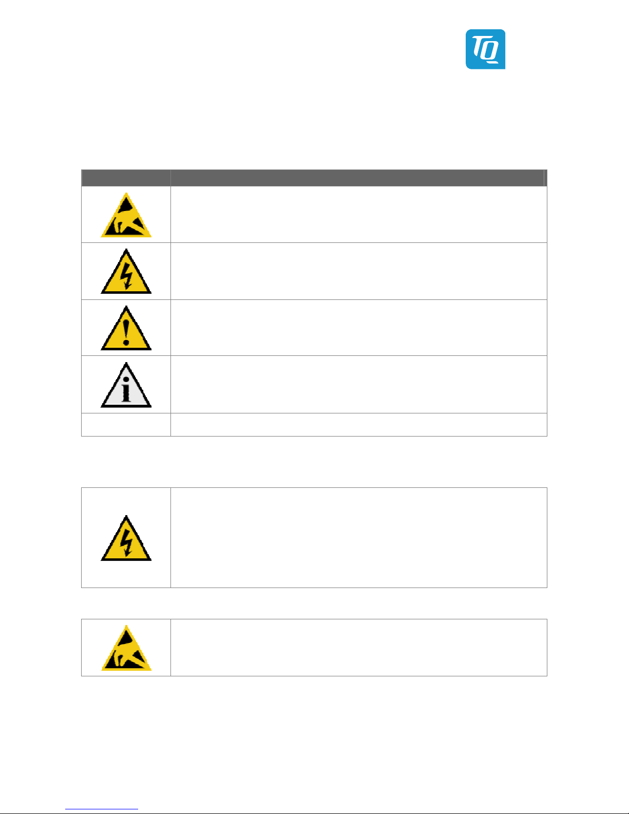
1.7 Symbols and Typographic Conventions
Table 1: Terms and Conventions
Symbol Meaning
This symbol represents the handling of electrostatic-sensitive modules and / or components. These
components are often damaged / destroyed by the transmission of a voltage higher than about 50 V.
A human body usually only experiences electrostatic discharges above approximately 3,000 V.
This symbol indicates the possible use of voltages higher than 24 V.
Please note the relevant statutory regulations in this regard.
Non-compliance with these regulations can lead to serious damage to your health and also cause
damage / destruction of the component.
This symbol indicates a possible source of danger. Acting against the procedure described can lead to
possible damage to your health and / or cause damage / destruction of the material used.
This symbol represents important details or aspects for working with TQ-products.
Command
A font with fixed-width is used to denote commands, contents, file names, or menu items.
1.8 Handling and ESD Tips
General handling of your TQ-products
The TQ-product may only be used and serviced by certified personnel who have taken note of the
information, the safety regulations in this document and all related rules and regulations.
A general rule is: do not touch the TQ-product during operation. This is especially important when
switching on, changing jumper settings or connecting other devices without ensuring beforehand
that the power supply of the system has been switched off.
Violation of this guideline may result in damage / destruction of the MB-COME10-1 module and be
dangerous to your health.
Improper handling of your TQ-product would render the guarantee invalid.
Proper ESD handling
The electronic components of your TQ-product are sensitive to electrostatic discharge (ESD).
Always wear antistatic clothing, use ESD-safe tools, packing materials etc., and operate your TQ-
product in an ESD-safe environment. Especially when you switch modules on, change jumper settings,
or connect other devices.

User's Manual l MB-COME10-1 UM 0101 l © 2016 TQ-Group Page 3
1.9 Naming of Signals
A hash mark (#) at the end of the signal name indicates a low-active signal.
Example: RESET#
If a signal can switch between two functions and if this is noted in the name of the signal, the low-active function is marked with
a hash mark and shown at the end.
Example: C / D#
If a signal has multiple functions, the individual functions are separated by slashes when they are important for the wiring.
The identification of the individual functions follows the above conventions.
Example: WE2# / OE#
1.10 Further Applicable Documents / Presumed Knowledge
• Specifications and manual of the modules used:
These documents describe the service, functionality and special characteristics of the module used.
• Specifications of the components used:
The manufacturer's specifications of the components used, for example CompactFlash cards, are to be taken note of.
They contain, if applicable, additional information that must be taken note of for safe and reliable operation.
These documents are stored at TQ-Systems GmbH.
• Chip errata:
It is the user's responsibility to make sure all errata published by the manufacturer of each component are taken note of.
The manufacturer’s advice should be followed.
• Software behaviour:
No warranty can be given, nor responsibility taken for any unexpected software behaviour due to deficient components.
• General expertise:
Expertise in electrical engineering / computer engineering is required for the installation and the use of the device.
Implementation information for the carrier board design is provided in the COM Express™ Design Guide (2) maintained by the
PICMG®. This Carrier Design Guide includes a very good guideline to design a COM Express™ carrier board.
It includes detailed information with schematics and detailed layout guidelines.
Please refer to the official PICMG® documentation for additional information (1), (2).

User's Manual l MB-COME10-1 UM 0101 l © 2016 TQ-Group Page 4
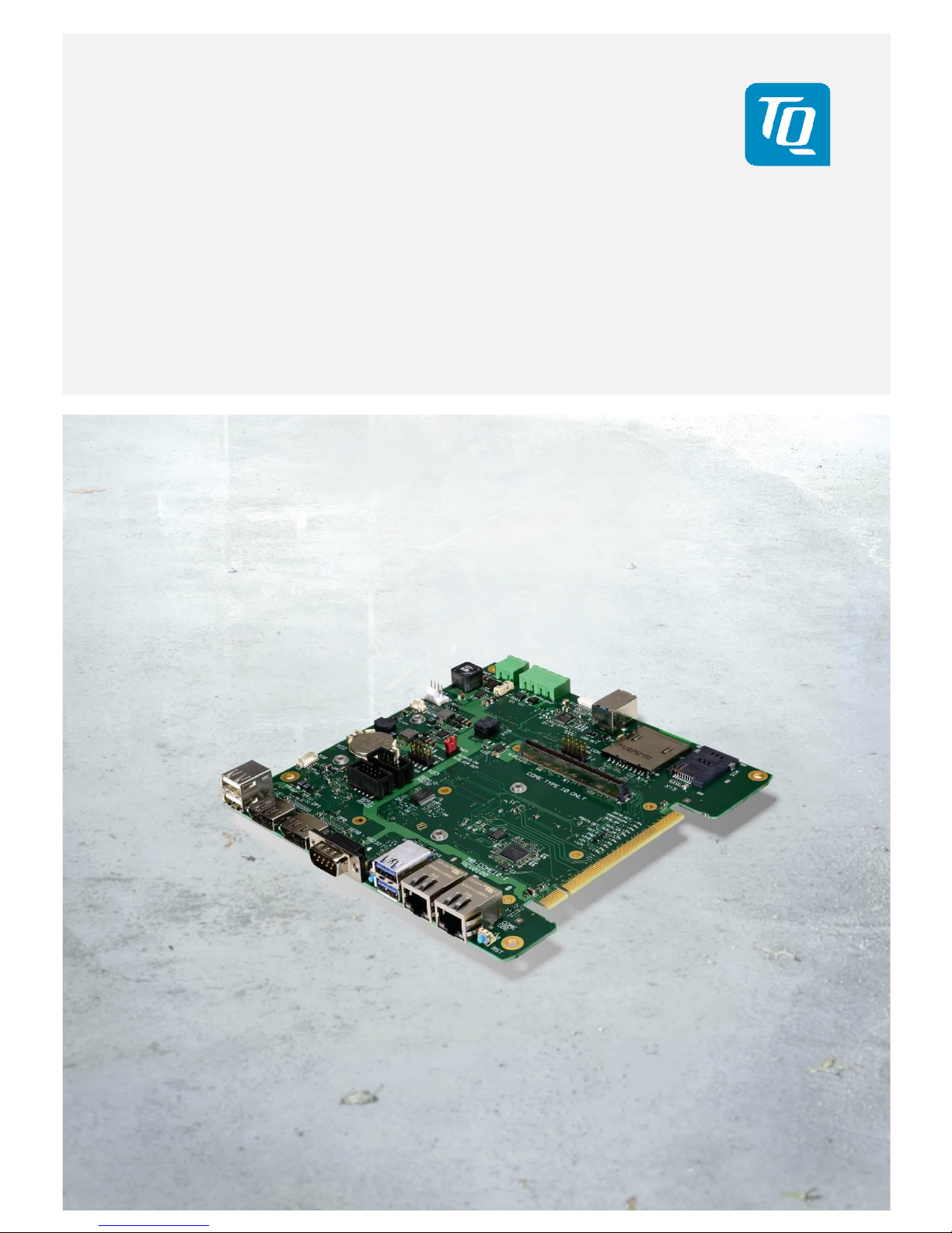
2. INTRODUCTION
The COM Express™ mainboard MB-COME10-1 is a carrier board for COM Express™ modules with Type 10 pinout. It can be used
for embedded computers or as evaluation platform for COM Express™ modules. In combination with a standard COM Express™
module it forms a very compact hardware kit that can be used for a freely scalable embedded PC platform thanks to its modular
design. Because of this – with uniform interfaces and mechanical dimensions – the PC system can be easily adjusted to suit the
requirements of the application. The many extension options and storage media that can be added offer a high level of flexibility
and allow functionalities and performance to be extended easily, quickly and inexpensively. Typical uses are found in embedded
server applications, PC systems for automation, visualisation and monitoring and all applications that place high demands on
quality, durability and long-term availability.
2.1 Functional Overview
The following key functions are implemented on the MB-COME10-1:
Supported Modules:
• COM Express™ Mini Modules with Type 10 pinout
External Interfaces:
• 2 × Gigabit Ethernet
• 4 × USB2.0 (1 × USB3.0)
• Up to 2 × DisplayPort (2
nd
DP is optional)
• RS232
• Power Button / Reset
Internal Interfaces:
• Embedded Display Port (optional)
• LVDS (optional)
• 1 × USB (e.g. for touch applications)
• 1 × USB 3.0 device
• Mini PCIe socket (with SIM Card support)
• mSATA socket
• SD card socket
• Socket for 2.5” HDD/SSD
• Audio: 1 × headphone out + 1 × microphone in + stereo speaker out
• RS232
• RS485/RS422
• Riser interface for PCIe add in cards
Power supply:
• Voltage: 12 V DC ±5 %
Environment:
• Extended temperature: –20 °C to +85 °C
Form factor / dimensions:
• 170 × 170 mm (Mini ITX)
2.2 Specification Compliance
The MB-COME10-1 supports modules compliant to the PICMG™ COM Express™ Module Base Specification (COM.0 R2.1) with
Type 10 pinout.
 Loading...