

TQ KRT2-S, KRT2-L, KRT2-P Operation And Installation Manual
Operation and Installation Manual
KRT2 VHF-Communication Transceiver
Doc.-No: KRT2.A-MAN.en
Rev. 0101
Page 1
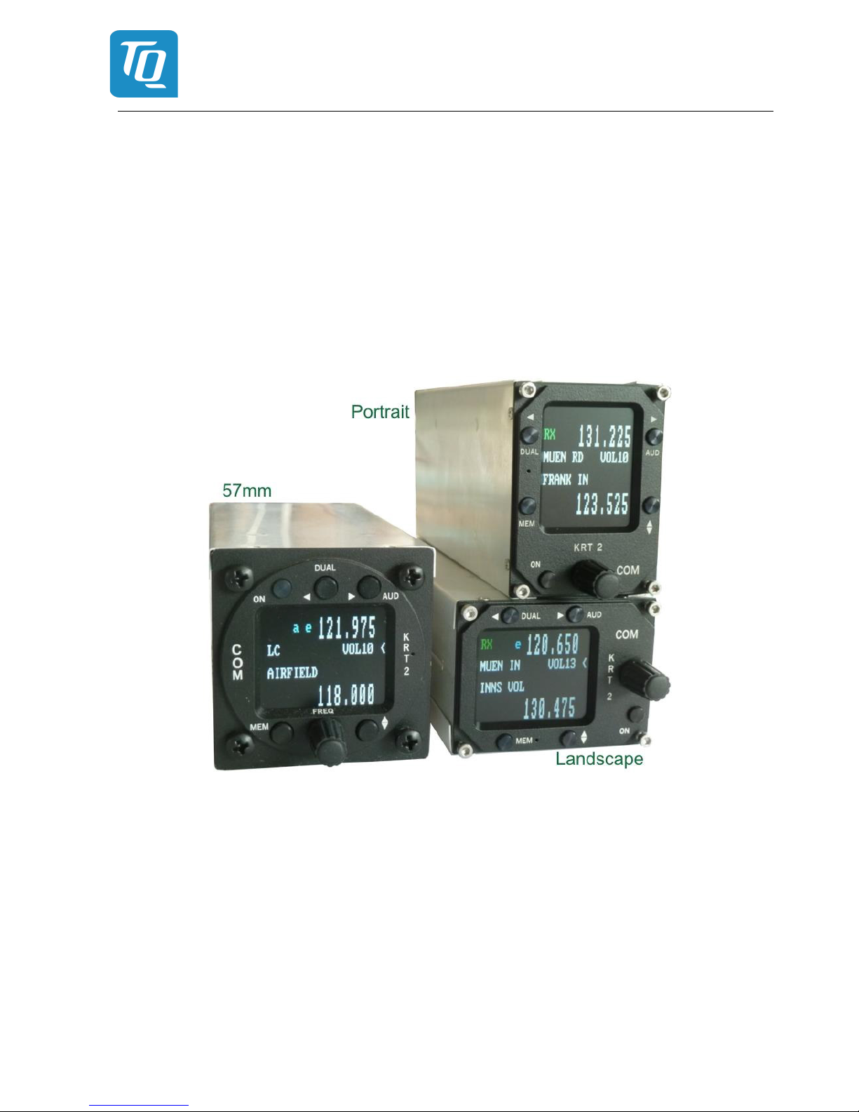
KRT2-S, KRT2-L, KRT2-P
VHF Communication
Transceiver
285942-xx(xx)-xx(xx) = KRT2-S (Standard Ø57mm)
285945-xx(xx)-xx(xx) = KRT2-L (Mini Landscape)
286048-xx(xx)-xx(xx) = KRT2-P (Mini Portrait)
285946-xx(xx)-xx(xx) = KRT-RC (Remote control Ø57mm for KRT2)
Operation- and Installation
Manual

Operation and Installation Manual
KRT2 VHF-Communication Transceiver
Doc.-No: KRT2.A-MAN.en
Rev. 0101
Page 2
Record of Revisions
Revision Date Topic
0100 24.03.2017 Initial Release
0101 16.01.2018 FCC supplements
Table 1: Record of Revisions

Operation and Installation Manual
KRT2 VHF-Communication Transceiver
Doc.-No: KRT2.A-MAN.en
Rev. 0101
Page 3
Service Bulletins (SB)
Service Bulletins must be inserted in the manual and added to this table.
No SB
No Rev.
Release date Date added Name
Table 2: Service Bulletins

Operation and Installation Manual
KRT2 VHF-Communication Transceiver
Doc.-No: KRT2.A-MAN.en
Rev. 0101
Page 4
Table of Contents
Record of Revisions ....................................................................................................................... 2
Service Bulletins (SB) ..................................................................................................................... 3
1. GENERAL ................................................................................................................................. 7
1.1 Symbols ............................................................................................................................ 7
1.2 Acronyms .......................................................................................................................... 7
1.3 Customer Service .............................................................................................................. 8
1.4 KRT2 Transceiver properties ............................................................................................. 8
2. Installation limitation .................................................................................................................. 9
2.1 Installation ......................................................................................................................... 9
2.2 Aircraft Radio ..................................................................................................................... 9
2.3 Quantitative safety objective identification ......................................................................... 9
2.4 Deviations.......................................................................................................................... 9
3. CONTROL general .................................................................................................................. 10
3.1 Control elements overview .............................................................................................. 10
3.2 Display ............................................................................................................................ 14
3.3 Menu levels ..................................................................................................................... 15
3.4 Self-test error reports ....................................................................................................... 15
4. OPERATION ........................................................................................................................... 16
4.1 General ........................................................................................................................... 16
4.2 ON / OFF switching ......................................................................................................... 16
4.3 Frequency selection ........................................................................................................ 17
4.3.1 Direct frequency selection ............................................................................................ 17
4.3.2 Frequency selection from favourites list ....................................................................... 18
4.3.3 Storing and editing favourites ...................................................................................... 18
4.4 AUD – Audio menu .......................................................................................................... 20
4.4.1 VOL – Volume ............................................................................................................. 20
4.4.2 SQ – Squelch .............................................................................................................. 20
4.4.3 VOX – Intercom voice trigger level setting ................................................................... 21
4.4.4 Manual Intercom .......................................................................................................... 21
4.4.5 TXm – PTT switch selection ........................................................................................ 21
4.4.6 INT – Intercom volume ................................................................................................ 22
4.4.7 EXT – External audio input volume .............................................................................. 22
4.4.8 DIM – Display brightness ............................................................................................. 22
4.4.9 BAT – Battery test........................................................................................................ 23
4.4.10 SIT – Side tone ........................................................................................................ 23
4.4.11 MIC – Setup ............................................................................................................. 23
4.4.12 Menu lock ................................................................................................................ 25
4.5 DUAL watch .................................................................................................................... 26
4.6 Transmitter Operation ...................................................................................................... 27
4.6.1 Two PTT configuration ................................................................................................. 28
4.6.2 Self-Test monitor ......................................................................................................... 28
4.6.3 Optical side tone .......................................................................................................... 28
4.7 Resetting to factory settings ............................................................................................ 29
4.8 SET UP - Menu ............................................................................................................... 29
4.8.1 ERASE – erasing of favourites list ............................................................................... 30
4.8.2 Channel spacing .......................................................................................................... 30
5. Remote Control ....................................................................................................................... 31
6. Installation ............................................................................................................................... 32
6.1 Installation hints ............................................................................................................... 32
6.2 Telecommunication data .................................................................................................. 32

Operation and Installation Manual
KRT2 VHF-Communication Transceiver
Doc.-No: KRT2.A-MAN.en
Rev. 0101
Page 5
6.3 FCC related issues .......................................................................................................... 33
6.3.1 Radiofrequency radiation exposure Information: .......................................................... 33
6.3.2 Note: ............................................................................................................................ 33
6.3.3 Compliance.................................................................................................................. 33
6.3.4 Modifications ................................................................................................................ 33
6.4 Scope of delivery ............................................................................................................. 34
6.5 Unpacking and inspecting the equipment ........................................................................ 34
6.6 Mounting ......................................................................................................................... 34
6.7 Electrical connections ...................................................................................................... 34
6.7.1 Microphone connection ................................................................................................ 35
6.7.2 Speaker & open microphone: ...................................................................................... 36
6.7.3 Earphone connection ................................................................................................... 36
6.7.4 External audio input ..................................................................................................... 36
6.7.5 Speaker connection ..................................................................................................... 36
6.8 Final audio setup ............................................................................................................. 37
6.8.1 For glider flights ........................................................................................................... 37
6.8.2 For motor gliders dual seaters ..................................................................................... 37
6.8.3 For motor planes ......................................................................................................... 37
6.9 Wiring .............................................................................................................................. 38
6.9.1 Wire Gauges ................................................................................................................ 38
6.9.2 Connector Pin-Configuration ........................................................................................ 38
6.9.3 General hint ................................................................................................................. 39
6.9.4 Wiring diagrams ........................................................................................................... 40
6.9.5 Wiring for dynamic microphones .................................................................................. 46
6.9.6 Connection support ST1 mating connector .................................................................. 46
6.10 Antenna ........................................................................................................................... 47
6.10.1 Antenna selection .................................................................................................... 47
6.10.2 Installation recommendation .................................................................................... 47
6.11 Microphone general ......................................................................................................... 48
6.12 Post-Installation Check .................................................................................................... 48
6.13 Starting Up ...................................................................................................................... 49
6.14 Accessories ..................................................................................................................... 49
6.15 Drawings ......................................................................................................................... 49
6.15.1 Dimensions .............................................................................................................. 49
6.15.2 Installation directions ............................................................................................... 51
7. Maintenance ........................................................................................................................... 52
7.1 Periodic Maintenance ...................................................................................................... 52
7.2 Repair .............................................................................................................................. 52
7.3 Cleaning .......................................................................................................................... 52
8. ANNEX.................................................................................................................................... 53
8.1 Frequency / channel - schedule ....................................................................................... 53
8.2 Technical Data ................................................................................................................ 54
List of Figures
Figure 1: KRT2-S Front View ............................................................................................................. 10
Figure 2: KRT2-P front view ............................................................................................................... 11
Figure 3: KRT2-L front view ............................................................................................................... 12
Figure 4: KRT2 active & standby frequencies .................................................................................... 26
Figure 5: KRT2 TX & RX operations .................................................................................................. 27
Figure 6: Headsets ............................................................................................................................. 35
Figure 7: Connector pinout ................................................................................................................. 38
Figure 8: Remote control pinout ......................................................................................................... 38

Operation and Installation Manual
KRT2 VHF-Communication Transceiver
Doc.-No: KRT2.A-MAN.en
Rev. 0101
Page 6
Figure 9: KRT2 connection support layout 1 ...................................................................................... 46
Figure 10: KRT2 connection support layout 2 .................................................................................. 47
Figure 11: KRT2-S Dimensions .......................................................................................................... 49
Figure 12: KRT2-P, KRT2-L dimensions ............................................................................................ 50
Figure 13: KRT2-RC remote control dimensions ................................................................................ 50
Figure 14: KRT2-S panel cutout ......................................................................................................... 51
Figure 15: KRT2-P, KRT2-L panel cutout ........................................................................................... 51
List of Tables
Table 1: Record of Revisions ............................................................................................................... 2
Table 2: Service Bulletins ..................................................................................................................... 3
Table 3: Acronyms ............................................................................................................................... 7
Table 4: KRT2 Controls...................................................................................................................... 13
Table 5: KRT2 Display ....................................................................................................................... 14
Table 6: KRT2 Menu Levels ............................................................................................................... 15
Table 7: KRT2 Built In Tests (BIT) ..................................................................................................... 15
Table 8: KRT2 Menu Lock ................................................................................................................. 25
Table 9: Telecommunication data ...................................................................................................... 32
Table 10: Scope of delivery ................................................................................................................ 34
Table 11: Frequencies ....................................................................................................................... 53
Table 12: Technical Data General ...................................................................................................... 54
Table 13: Technical Data Transmitter ................................................................................................ 55
Table 14: Technical Data Receiver .................................................................................................... 55
Operation and Installation Manual
KRT2 VHF-Communication Transceiver
Doc.-No: KRT2.A-MAN.en
Rev. 0101
Page 7
1. GENERAL
This manual contains information about the physical, mechanical and electrical properties as well as a
description for the operation and installation of the VHF airborne transceiver KRT2.
1.1 Symbols
WARNING
Non-compliance may cause personnel injury due to radiation or fire.
CAUTION
Non-compliance may cause damage or incorrect operation of the transceiver.
INFORMATION
1.2 Acronyms
Abbreviation Description Definition
BAT Battery (Electrical) Check DC source
DIM Dimming Display brightness setting
EXT Exterior / External External Audio input level setting
INT Intercom level Intercom volume level setting
PTT Push-To-Talk Transmitter activation
RC Remote control KRT2-RC remote control for KRT2
SQ Squelch Squelch setting
VOX Voice operated intercom Voice level setting for intercom activation
Table 3: Acronyms

Operation and Installation Manual
KRT2 VHF-Communication Transceiver
Doc.-No: KRT2.A-MAN.en
Rev. 0101
Page 8
1.3 Customer Service
In order to process returned units most expeditiously, please use the email
support.krt@tq-avionics.com on the website www.tq-avionics.com
.
Suggestions which will improve this manual are very much appreciated at:
info@tq-avionics.com
.
Information concerning software updates is available under
support.krt@tq-avionics.com
.
1.4 KRT2 Transceiver properties
• VHF airborne transceiver
• Frequency range 117.975 to 137.000 MHz
• Channel spacing 8,33 / 25 kHz (2278 channels)
• Fast channel selection
• 2 separate microphone inputs (standard or dynamic)
• Audio-input for other audio devices
• Installation: Standard panel cut-out (57 mm)
• Integrated Intercom
• 100 user definable frequencies with up to 8 character/spaces identifiers
Continuous transmissions will be turned off after 2 minutes.
(Stuck microphone function)

Operation and Installation Manual
KRT2 VHF-Communication Transceiver
Doc.-No: KRT2.A-MAN.en
Rev. 0101
Page 9
2. Installation limitation
The conditions and tests required for (E)TSO approval of this article are minimum performance
standards. It is the responsibility of those installing this article either on or within a specific type or
class of aircraft to determine that the aircraft installation conditions are within the (E)TSO standards.
(E)TSO articles must have separate approval for installation in aircraft.
2.1 Installation
For installation hints, data, electrical connections and mounting instructions please see section 6 “In-
stallation”.
2.2 Aircraft Radio
The KRT2 was designed as a closed unit for installation in a cockpit environment of the general aviation with the following limitations:
Installation must be in accordance with the applicable EASA or FAA requirements.
The classification of the software approval is suitable for aircraft type.
The failure classification identified in accordance with FAA AC 23.1309-1D is:
MINOR
The Software level is:
LEVEL D
2.3 Quantitative safety objective identification
In accordance with EASA regulations, the goal is a safety objective for the VHF COM radio in the
KRT-2 VHF Communication Transceiver System of 1 x 10E-4 per flight hour for Class I airplanes and
1 x 10E-5 per flight hour for Class II Airplanes.
2.4 Deviations
None
Operation and Installation Manual
KRT2 VHF-Communication Transceiver
Doc.-No: KRT2.A-MAN.en
Rev. 0101
Page 10
3. CONTROL general
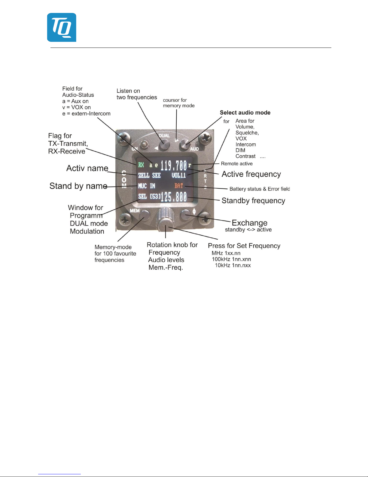
3.1 Control elements overview
Figure 1: KRT2-S Front View
Operation and Installation Manual
KRT2 VHF-Communication Transceiver
Doc.-No: KRT2.A-MAN.en
Rev. 0101
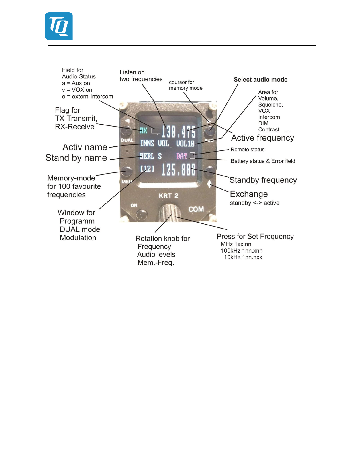
Page 11
Figure 2: KRT2-P front view
Operation and Installation Manual
KRT2 VHF-Communication Transceiver
Doc.-No: KRT2.A-MAN.en
Rev. 0101
Page 12
Figure 3: KRT2-L front view
All functions and performances of the normal size unit (57mm round) and the Portrait format (Mini) are
identical.
The only differences are the text areas on the display Compare Figure 2: KRT2 Front view and Figure
3: KRT2 Mini Front view for more details.
Operation and Installation Manual
KRT2 VHF-Communication Transceiver
Doc.-No: KRT2.A-MAN.en
Rev. 0101
Page 13
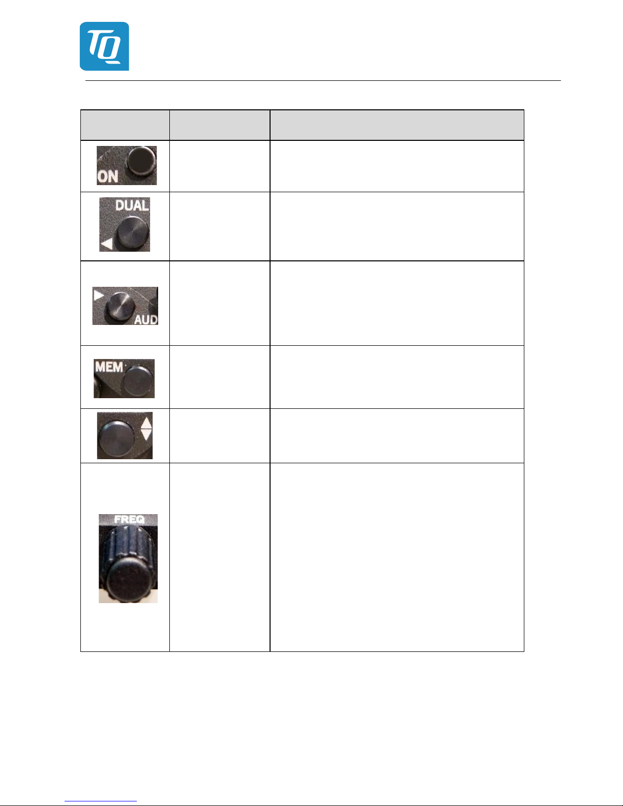
Button Function Usage
ON / OFF Self-locking switch
DUAL WATCH
1. Scanning between the Active and Standby frequencies
2. Positioning cursor to the left when programming
the station identifier
AUDIO SELECT
1. Stepping through the audio menus
2.
VOL SQ VOX TX INT EXT DIM CON SIT and MIC
3. Positioning cursor to the right when programming
the station identifier
FAVORITES
1. Frequency and identifier selection from the favourites list
2. Programming of favourites (frequency and identifier)
EXCHANGE
Exchange of the Active and Standby frequencies
TURNING KNOB
Pressing for Selection of the frequency range to:
MHz, 100kHz, 10kHz
Toggles between frequency and identifier when programming the favourites
Sets all variable values in any menu
• Volume setting of headsets and speakers
• MHz/kHz selection of the standby
• frequency in 3 different ranges
• Favourite selection
• Alpha character selection when programming
favourites
• Change of microphone settings
Table 4: KRT2 Controls

Operation and Installation Manual
KRT2 VHF-Communication Transceiver
Doc.-No: KRT2.A-MAN.en
Rev. 0101
Page 14
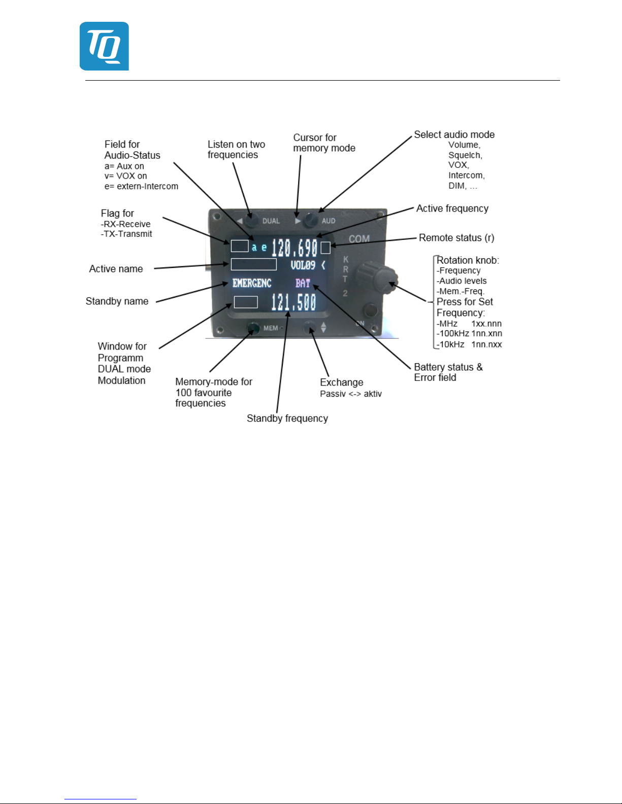
3.2 Display
Indication Meaning Remark
RX Reception RX is displayed during reception (squelch
opened)
TX Transmission Transmitter operates normally
Te Transmitter was turned off automati-
cally after 2 min continuous operation
119.700 Frequency
ZELL SEE Frequency station identifier Displayed when frequency and identifier are
stored in the favourite list
MUC IN Standby frequency station identifier Displayed when frequency and identifier are
stored in the favourite list
VOL …… Receiver volume level (default after a
certain time delay)
When AUD is pressed the corresponding Audio
Menu item and setting is displayed
DUAL DUAL function is activated DUAL function is deactivated by DUAL, FREQ or
MEM
[03] (MEM) Favourite list index (0-99) When frequency and identifier are stored at this
index ex:[03] they are displayed
125.100 upper Active frequency Displayed in large fonts.
125.800 lower Standby/DUAL - frequency Displayed in large fonts.
< The pointer indicates what the turning
knob will change VOL SQ VOX…..etc.
Standby frequency
Arrow is positioned according to the button
pressed (AUD or FREQ)
BAT Supply voltage is low <10,5V Low or defective battery / generator.
A-match Antenna error Bad antenna match
a v e Status of certain Audio menu func-
tions
a = AUX. Input active
v = VOX active
e = external Intercom switch active
Table 5: KRT2 Display

Operation and Installation Manual
KRT2 VHF-Communication Transceiver
Doc.-No: KRT2.A-MAN.en
Rev. 0101
Page 15
3.3 Menu levels
Displayed Signification Remark
VOL Volume Default
SQ Squelch
VOX Voice operated Voice operated intercom
DIM Display brightness
BAT(tst) DC source check
INT Intercom - Volume
EXT Volume of external devices
TX(m)** PTT button selection Left/Right/Both
SIT Side tone During transmitter operation
MIC Setup-Menu for Microphones Service-Menu without radio opera-tion.
Table 6: KRT2 Menu Levels
3.4 Self-test error reports
Display Meaning Remark
Er_PLL Internal error, no transmission Return the transceiver for maintenance
Er_ADC Internal error, operation limited Return the transceiver for maintenance
Er_FPA Internal error; unit not usable Return the transceiver for maintenance
Er_I2C Internal error; unit not usable Return the transceiver for maintenance
Er_D10 Internal error; reception corrupt Return the transceiver for maintenance
Error_3V3 Internal error; unit not usable Return the transceiver for maintenance
Key_Block Internal error; unit not usable Return the transceiver for maintenance
Table 7: KRT2 Built In Tests (BIT)
Operation and Installation Manual
KRT2 VHF-Communication Transceiver
Doc.-No: KRT2.A-MAN.en
Rev. 0101
Page 16
4. OPERATION
4.1 General
In the normal operating mode in which the turning knob always is connected to the volume (VOL).
The normal operating mode can be left by pressing the AUD, FREQ or MEMORY button.
When not in the normal mode and there is no pilot action for more than 10 seconds the unit returns to
the normal mode.
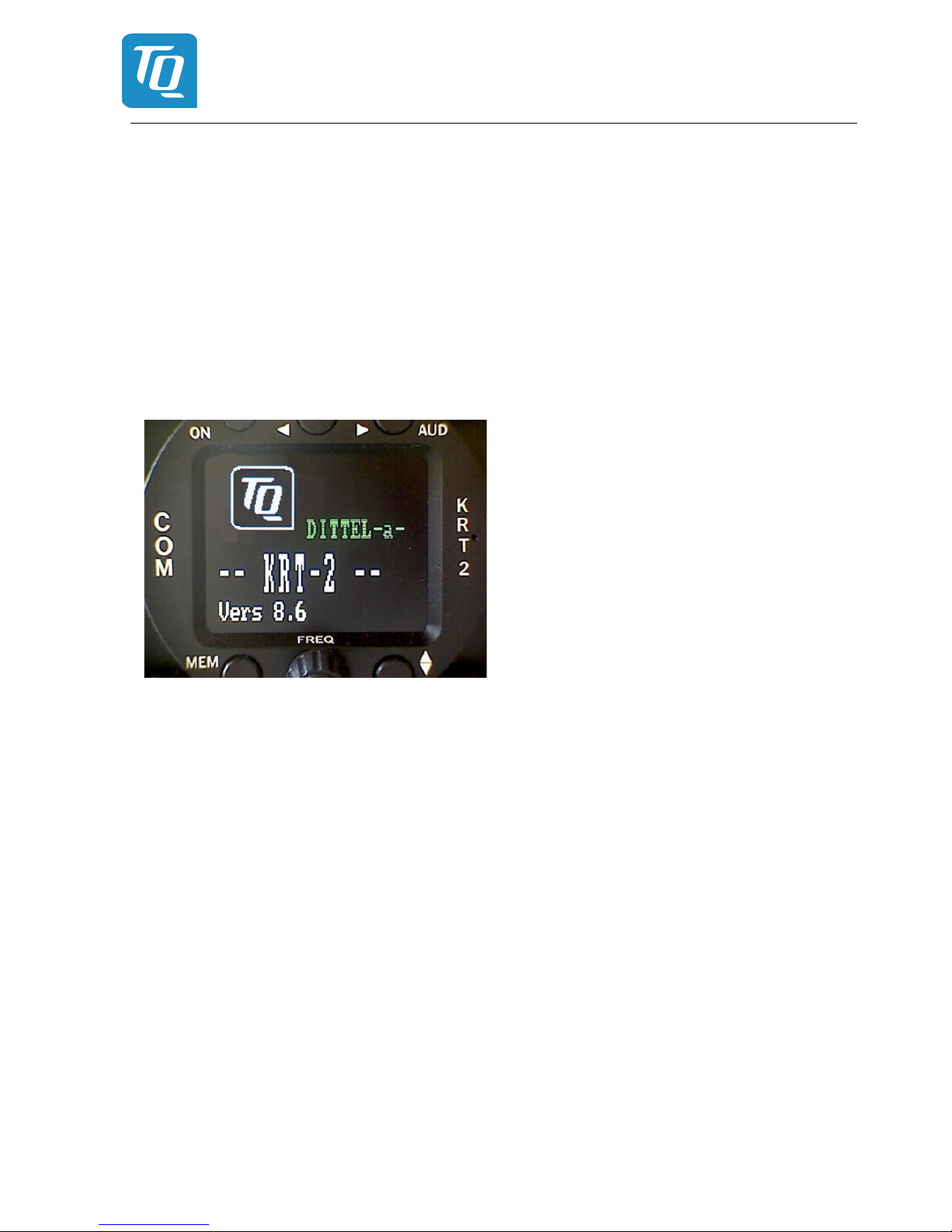
4.2 ON / OFF switching
ON / OFF switching is done by pushing the self-locking switch.
After power up the following display will be displayed:
Device-name
KRT2
Software Version e.g. V8.6
(Example)
The unit starts in the normal operating mode using and displaying the data last used.
Operation and Installation Manual
KRT2 VHF-Communication Transceiver
Doc.-No: KRT2.A-MAN.en
Rev. 0101
Page 17
4.3 Frequency selection
There are two different frequency selection methods:
• Direct Input
• Selection from the favourite list (index 0-99)
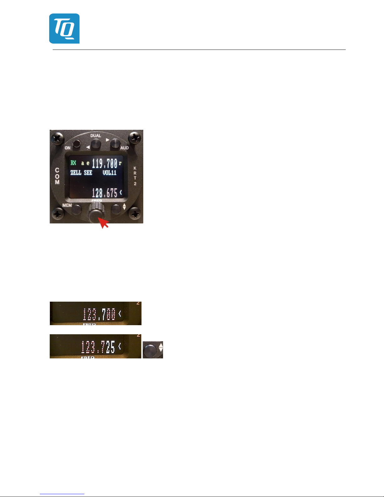
4.3.1 Direct frequency selection
The Standby-Frequency is set with the turning knob in 3 different ranges. The selected range is highlighted and can be changed with the FREQ button. Frequency ranges are:
1xx.nnn
1nn.xnn
1nn.nxx
Press the FREQ button once or several times until the desired frequency range is highlighted. The
unselected digits are displayed as dotted digits.
When the pointer is not next to the Standby Frequency window, it
will be repositioned with the first pressing of the FREQ button.
Exchanges the Active and Standby frequencies.
When the Exchange button is not pressed, the Standby frequency display will return to its normal appearance after 20 seconds.
 Loading...