

Page 1
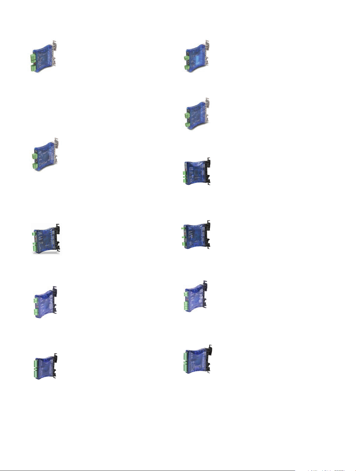
For the latest prices, please check AutomationDirect.com.
FC Series Signal Conditioners
FC-33
DC Selectable Signal Conditioner with
FC-11
4-20 mA Isolated Signal Conditioner
3-way isolation
Field configurable input and output ranges of 0-5V, 0-10 V,
0-20 mA and 4-20 mA with 1500 VDC isolation between
input and output, and 1500 VDC isolation from 24 volt power
and input/output. LED indicates normal operation and is used
in conjunction with the calibration pushbutton for the internal
calibration process.
• 3-way 1500 V isolation
• Push button calibration
FC-T1
Thermocouple/mV Isolated Signal
Conditioner
Field configurable input for type J, K, E, T, R, S, B, N and C
thermocouples or ±156.25 mV inputs with 1500 VDC isolation
between input and the 4-20 mA output. Cold junction compensation and burnout detection. Alarm/run LED.
• 1500 V isolation
• Cold junction compensation (CJC)
• Internal diagnostics (burnout detection or calibration errors)
Loop powered 4-20 mA input/output signal with 1500 VDC
isolation between input and output.
• 1500 V isolation • Loop powered
FC-R1
RTD Input Signal Conditioner
Loop powered, non-isolated, 3-wire unit converts an RTD input
to a linear 4-20 mA signal. User selectable CU10, PT100 or
PT1000 input.
FC-P3
Potentiometer Input, Analog Output
Signal Conditioner
Field configurable input and output, input ranges of 3-wire
potentiometer 0 to 100 ohms through 0 to 100 kilohms, and
output ranges of 0-5V, 0-10 V, 0-20 mA or 4-20 mA. Field
calibrated to 10% of potentiometer full range.
FC-B34
FC-35B
Unipolar Voltage or Current to Bipolar
Voltage Signal Conditioner
Field configurable input and output, unipolar input ranges of
0-5V, 0-10 V, 0-20 mA or 4-20 mA, and bipolar output ranges of
±100 mV, ±50 mV, ±5V, ±10V, ±15V. Field calibrated with
offset and span adjustments.
Field configurable input and output, bipolar input ranges of
±100 mV, ±50 mV, ±5V, ±10V, ±15V, and unipolar output
ranges of 0-5V, 0-10 V, 0-20 mA or 4-20 mA. Field calibrated
Bipolar Voltage to Unipolar Voltage or
Current Signal Conditioner
with offset and span adjustments.
FC-3RLY2
Analog Input, 2-Relay, Limit Alarm
Field configurable analog to relay limit alarm powered by 24VAC/
VDC and Input signal ranges of 0-15V, 0-30V or 0-20mA. Trip/
Release Point programmed via DIP switches. LED’s indicate
operating status.
FC-ISO-D
Encoder Signal Conditioner and Optical
Isolator - Differential Line Driver Output
Ideal for use with single-ended (open collector, NPN, pull-up,
push-pull, totem pole) or differential line driver encoders. Three
complementary inputs (A, B, Z, A-not, B-not, Z-not) are rated
for 4.5-7.5 and 12-26 VDC and frequency response up to
1 MHz.
Optical isolation separates the input signals from three differential
line driver outputs (A, B, Z, A-not, B-not, Z-not) rated for 5VDC.
tPSC-1
Signal Conditioners
FC-3RLY4
Analog Input, 4-Relay, Limit Alarm
Field configurable analog to relay limit alarm powered by 24VAC/
VDC and Input signal ranges of 0-15V, 0-30V or 0-20mA. Trip/
Release Point programmed via DIP switches. LED’s indicate
operating status.
FC-ISO-C
Encoder Signal Conditioner and Optical
Isolator - Open Collector Output
Ideal for use with single-ended (open collector, NPN, pull-up,
push-pull, totem pole) or differential line driver encoders. Three
complementary inputs (A, B, Z, A-not, B-not, Z-not) are rated
for 4.5-7.5 and 12-26 VDC and frequency response up to
1 MHz.
Optical isolation separates the input signals from three
complementary open collector outputs (A, B, Z, A-not, B-not,
Z-not) rated for 5-36 VDC that can be used in single-ended
configurations.
1-800-633-0405
Page 2
For the latest prices, please check AutomationDirect.com.
FC-33 DC Selectable Signal Conditioner
$130.00
UL file E200031
Overview
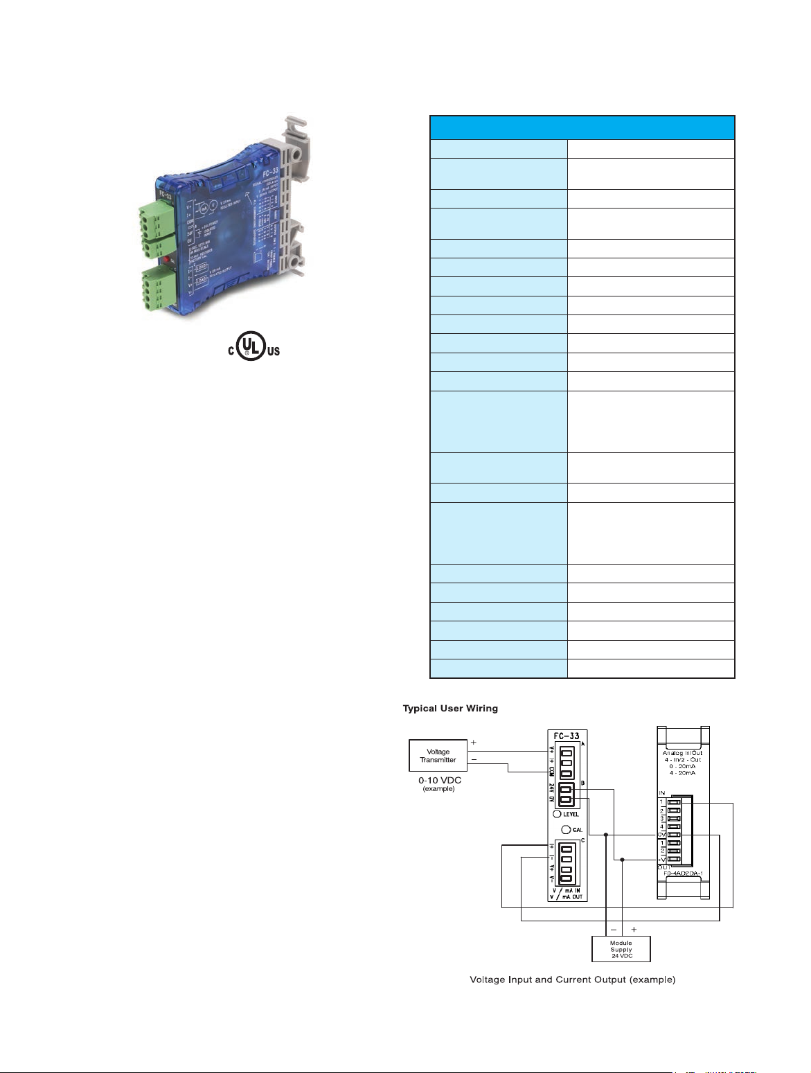
The FC-33 is a DIN-rail or side-mount, selectable input/output
signal conditioner with 1500 VDC isolation between input and
output, and 1500 VDC isolation between 24-volt power and input/
output. The field configurable input/output types allow a wide
ranging capability for 0-5V, 0-10V, 0-20 mA and 4-20 mA signals.
The FC-33 has built-in self-calibration, but also has OFFSET (zero)
and SPAN (full scale) adjustments of the output signal. The OFFSET
has an adjustment range of 0 to 25% of full scale input and the
SPAN has an adjustment of 80% to 102%.
Level LED: The LED is a powerful tool when setting up the signal
conditioner. During normal operation the LED will blink at a proportional rate to the selected input signal level. When performing field
calibration the LED is used for indication of the internal calibration
process.
CAL-Pushbutton: This pushbutton, along with various switch
settings, allows you to calibrate the OFFSET and/or SPAN for your
application or to restore factory default calibration.
Specifications
Input Ranges
Input Impedance
Output Ranges
Load Impedance
Maximum Load / Current
Sample Duration Time
Filter Characteristic
Linearity Error
Stability
Accuracy vs. Temperature
Input Power
Recommended Fuse
Isolation
Maximum Inaccuracy of
Output
Output Current
Approx. Field Cal. Range
Operating Temperature
Storage Temperature
Relative Humidity
Vibration
Shock
Noise Immunity
0-5 V, 0-10 V, 0-20 mA, 4-20 mA
250 q, ±0.1% current input
200 Kq / 400 Kh Voltage input
0-5 V, 0-10 V, 0-20 mA, 4-20 mA
2 Kq minimum, voltage output
0 q minimum, current output
550 q @ 24 VDC (sink/source)
10 mS
-3 dB @ 3 Hz, -6 dB/octave
0.05% FSO maximum
0.05% FSO maximum
0.005%/ °C, (50ppm/°C)
24 VDC, ±10% @ 50 mA
0.032 mA, Series 217, current inputs
1500 VDC input - output*
1500 VDC power - input*
1500 VDC power - output*
*applied for 1 second
0.05% @ 25°C, FSO maximum
0.25% @ 0-60°C, FSO maximum
21 mA maximum (for mA output)
0 - 25%
(0 - 1.5 V / 5 V mode)
80% - 102%
(4 - 5.1 V / 5 V mode)
0-60°C (32 to 140°F)
-20 to 70°C (-4 to 158°F)
5 to 90% (non-condensing)
ML STD 810C 514.2
ML STD 810C 516.2
NEMA ICS3-304
Application
The FC-33, field configurable isolated input/output signal
conditioner, is useful in eliminating ground loops and interfacing sensors to PLC analog input modules. The FC-33 has
3-way isolation; this feature solves many types of configuration problems. For example, the signal conditioner can be
configured for a sinking input and a sourcing output. It also
allows signal translation from current input to voltage output
or voltage input to current output.
This feature would be useful in a system design with a limited
type and number of channels – for example: eight channels of
0-10 VDC, seven of which are used, and one 4-20 mA input
transmitter.
tPSC-2
Signal Conditioners
1-800-633-0405
Page 3
For the latest prices, please check AutomationDirect.com.
FC-11 4-20mA Isolated Signal Conditioner
$97.00
Specifications
UL file E200031
Overview
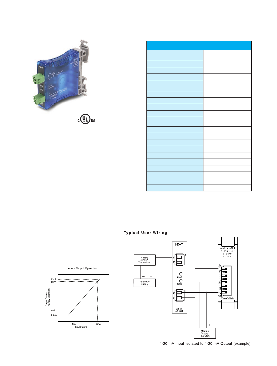
The FC-11 is a DIN-rail or side-mount, 4-20 mA Input/Output
loop powered signal conditioner with 1500 VDC isolation
between input and output.
The FC-11 has a user-selectable factory calibration. The output
can also be calibrated with OFFSET (zero) and SPAN (full scale)
adjustments. The OFFSET has an adjustment range of 0 to 25%
of full scale input and the SPAN has an adjustment of 80% to
102%.
Application
The FC-11 isolated input/output signal conditioner is useful in
eliminating ground loops and sinking/sourcing issues when interfacing to PLC analog input modules. The FC-11 design feature
solves many types of configuration problems. For example, the
signal conditioner can solve the problem of connecting a sinking
input transmitter to a sinking analog input module.
Input Ranges
Extended Input range
Input Burden Voltage
1
2
Maximum Input Current
Output Burden Voltage
3
Output Range
Extended Output Range
1
Maximum Load Impedance
Maximum Output Current
Sample Duration Time
Linearity Error
Max Inaccuracy of Output
Filter Characteristics
Stability
Accuracy vs. Temperature
Isolation
Operating Temperature
Storage Temperature
Relative Humidity
Vibration
Shock
Noise Immunity
NOTES:
1. When adjusting SPAN and OFFSET potentiometer
2. Voltage required to power internal circuitry
3. Formula, [(output load) x 20 mA] + 8.5 V,.i.e.: 13.5 VDC @ 250 q
4. Internal analog converter resolution is 12-bit
4-20 ma
3.5 mA to 20.6 mA, ± 1%
6.8 VDC
34 mA @ 9.7 VDC
8.5 VDC minimum
4-20 mA
3.5 mA to 20.6 mA, ± 1%
650 q @ 24 VDC, 1000 q 29 VDC
23 mA @ 29 VDC
18 mS maximum
0.1% FSO maximum
0.05% @ 25°C, FSO maximum,
0.3% @ 0-60°C, FSO maximum
-3 dB @ 200 Hz, -6 dB / octave
0.1% FSO maximum
± 0.0065% / °C (65ppm / °C)
1500 VDC Input - Output
0 to 60°C (32 to 140°F)
-20 to 70°C (-4 to 158°F)
5 to 90% (non-condensing)
ML STD 810C 514.2
ML STD 810C 516.2
NEMA ICS3-304
tPSC-3
Signal Conditioners
1-800-633-0405
Page 4
For the latest prices, please check AutomationDirect.com.
FC-T1 Thermocouple/mV Input Isolated
Signal Conditioner
$130.00
UL file E200031
Overview
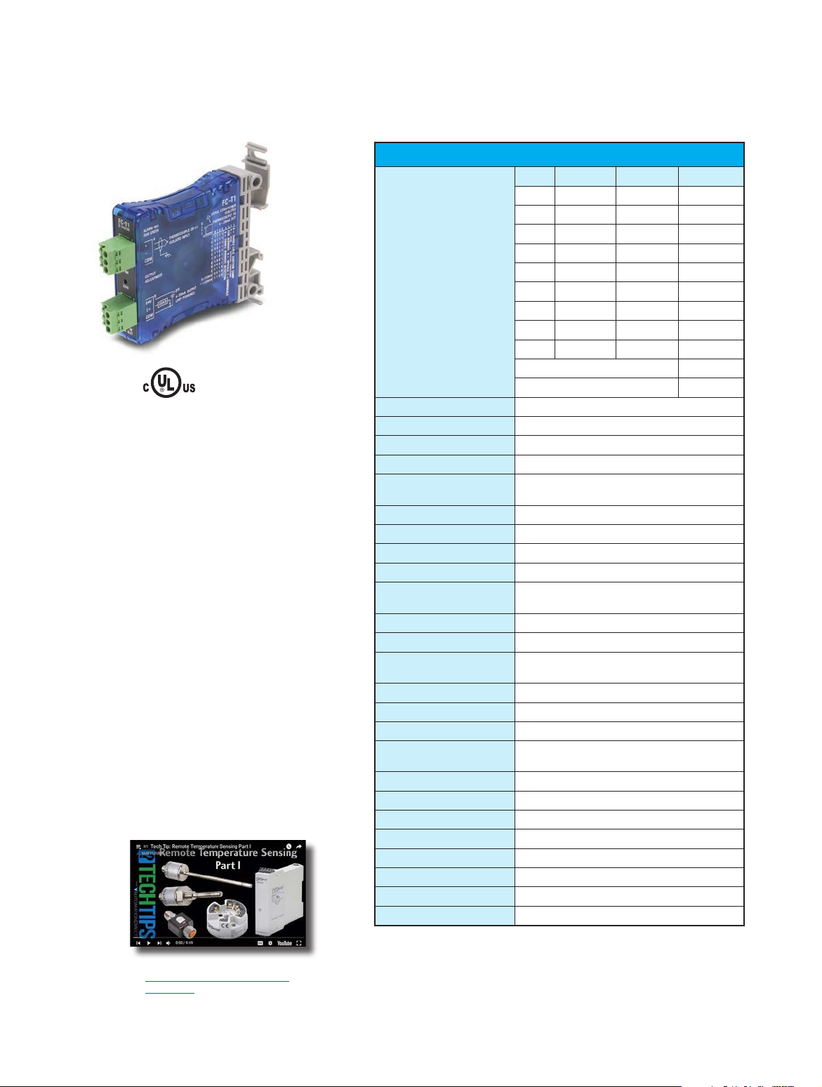
The FC-T1 is a DIN-rail or side-mount
thermocouple/mV input signal conditioner with 1500
VAC isolation between input and output.
The field configurable input allows a wide ranging
capability for a type J, K, E, R, S, T, B, N and C thermocouple, or 0-156.25 mV and w156.25 mV signals.
The FC-T1 has built-in self-calibration, but also offers
OFFSET (zero) and SPAN (full scale) potentiometer for
adjustment of the output signal.
The FC-T1 is also equipped with cold junction
compensation (CJC) circuitry to provide an internal
ice-point reference.
The temperature calculation and linearization are
based on data provided by the National Institute of
Standards and Technology (NIST).
ALARM and RUN LED: This LED is bicolor (red and
green). A red LED indicates either power up, a fault
with internal calibration, or a thermocouple burnout
condition, while a green LED indicates normal operation.
Burnout Function: The output current can be selected
to provide either upscale (20mA) or downscale (4mA)
detection whenever thermocouple burnout occurs.
Click on the thumbnail or go to
https://www.automationdirect.com/
VID-TE-0006 for a short video on
Remote Temperature Sensing
Specifications
T/C °C °F Resolution
J -190 to 760 -310 to 1400 0.23°C
K -150 to 1372 -238 to 2502 0.37°C
E -210 to 1000 -345 to 1832 0.295°C
R 65 to 1768 149 to 3214 0.42°C
Input Ranges
Output Range
External Power Supply
Input Impedance
Absolute Maximum Rating
Maximum Inaccuracy
Linearity Error
Over Temperature Error
Insulation Resistance
Isolation
Sample Duration Time
Common Mode Rejection
Input Filter (FIR)
Broken Thermocouple
Over Range
Under Range
Burnout Time
Cold Junction
Compensation
Warm-up Time
Operating Temperature
Storage Temperature
Relative Humidity
Environmental Air
Vibration
Shock
Noise Immunity
Note:
1
Internal analog converter resolution is 12-bit.
S 65 to 1768 149 to 3214 0.42°C
T -230 to 400 -382 to 752 0.15°C
B 529 to 1820 984 to 3308 0.315°C
N -70 to 1300 -94 to 2372 0.33°C
C 65 to 2320 149 to 4208 0.55°C
0 to 156.25 mV 0.038 mV
-156.25 mV to +156.25 mV 0.076 mV
4 to 20 mA
15 mA, 22 to 26 VDC
>5 Mq
Fault protected input ±50 V
±3°C, Temperature Input
±0.1%, Voltage Input
0.1%
0.1 X 10⁻⁵% (10 ppm)/°C
M100 Mr with 500 VDC (Input to output power)
1500 VAC @ 1 Sec. (Input to output commons)
120 mS Voltage Input
250 mS Thermocouple Input
-100 dB @ DC, -90 dB @ 50/60 Hz
-3 dB @ 15 Hz, -100 dB @ 50 Hz, -100 dB @ 60 Hz
Up/Down Scale
Red/Green LED
Up Scale
Down Scale
m3 Seconds
Automatic
30 min. typical ±1°C repeatability
0 to 60°C (32 to 140°F)
-20 to 70°C (-4 to 158°F)
5 to 90% (non-condensing)
No corrosive gases permitted
ML STD 810C 514.2
ML STD 810C 516.2
NEMA ICS3-304
1
tPSC-4
Signal Conditioners
1-800-633-0405
Page 5
For the latest prices, please check AutomationDirect.com.
FC-T1 Thermocouple/mV Input Isolated
Signal Conditioner
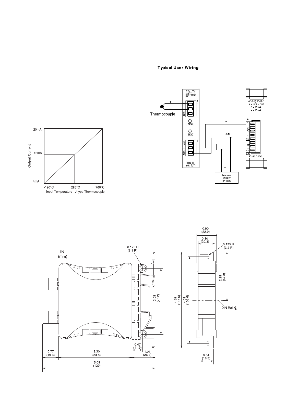
Application
The FC-T1, field configurable thermocouple/mV signal
conditioner, is useful in eliminating ground loops and
for interfacing to PLC analog input modules. If your
requirements are only for one channel of temperature,
you can add the signal conditioner to your 4-20 mA input
module. Or, if your requirements are for a single millivolt
signal source, you have the option of adding this input to
your analog module.
Signal Conditioner Dimensions
These dimensions are typical for all of the signal conditioners.
All dimensions are in inches (millimeters).
tPSC-5
Signal Conditioners
1-800-633-0405
Page 6
For the latest prices, please check AutomationDirect.com.
FC-R1 RTD Input Loop Powered Signal
Conditioner
$130.00
UL file E200031
Overview
The FC-R1 is a DIN-rail or side-mount
Resistive Temperature Detector signal
conditioner. It is a non-isolated signal conditioner which converts a 3-wire RTD to a
linearized 4-20 mA current loop signal.
The FC-R1 has a user selectable CU10 (10
Ohm copper), PT100 (100 Ohm platinum)
or PT1000 (1000 Ohm platinum) RTD input,
and also offers OFFSET (zero) and SPAN (full
scale) adjustments of the output signal. The
OFFSET has an adjustment range of 0 to
25% of full scale output and the SPAN has an
adjustment of 80% to 102%.
Input Ranges
RTD Excitation Current
Common Mode Range
Output Range
Maximum Inaccuracy
Maximum Loop Supply
Load Impedance
Maximum Load/Power Supply
Linearity Error
Output Slew Rate
Filter Characteristics
Stability
Operating Temperature
Storage Temperature
Relative Humidity
Environmental Air
Vibration
Shock
Noise Immunity
Specifications
CU10 -200°C to 260°C -328°F to 500°F
PT100 -200°C to 850°C -328°F to 1562°F
PT1000 -200°C to 595°C -328°F to 1103°F
CU10, PT100 500 µA ±50 µA
PT1000 80 µA ±20 µA
0 - 3.5 VDC
4-20 mA (linearized)
0.35% FSO / CU10
0.2% FSO @ 25°C / PT100 & PT1000
0.26% FS0 @ 60°C / PT100 & PT1000
30 VDC
0 q minimum
203 q / 12 V, 745 q / 24 V
0.35% FSO / CU10
0.2% FSO / PT10 & PT1000
1% @ 20 mS
105 dB @ DC, 60 dB @ 10 Hz, 40 dB @ 60Hz
0.05% FSO maximum
0 to 60°C (32 to 140°F)
-20 to 70°C (-4 to 158°F)
5 to 90% (non-condensing)
No corrosive gases permitted
ML STD 810C 514.2
ML STD 810C 516.2
NEMA ICS3-304
Click on the thumbnail or go to
https://www.automationdirect.com/
VID-TE-0006 for a short video on
Remote Temperature Sensing
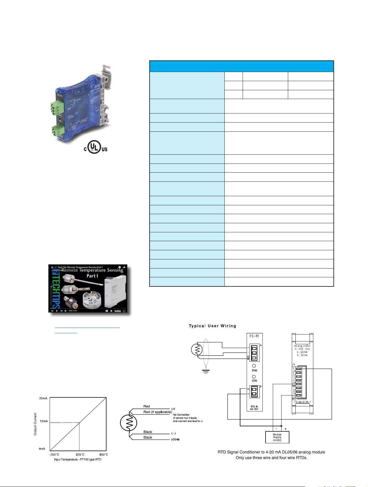
Application
The FC-R1 field configurable input signal conditioner is
useful for interfacing RTD sensors to PLC analog current input
modules. It is recommended that shielded RTDs be used
whenever possible to minimize noise on the input signal.
tPSC-6
Signal Conditioners
1-800-633-0405
Page 7
For the latest prices, please check AutomationDirect.com.
FC-P3 Potentiometer Input, Analog Output
Signal Conditioner
$129.00
UL file E157382
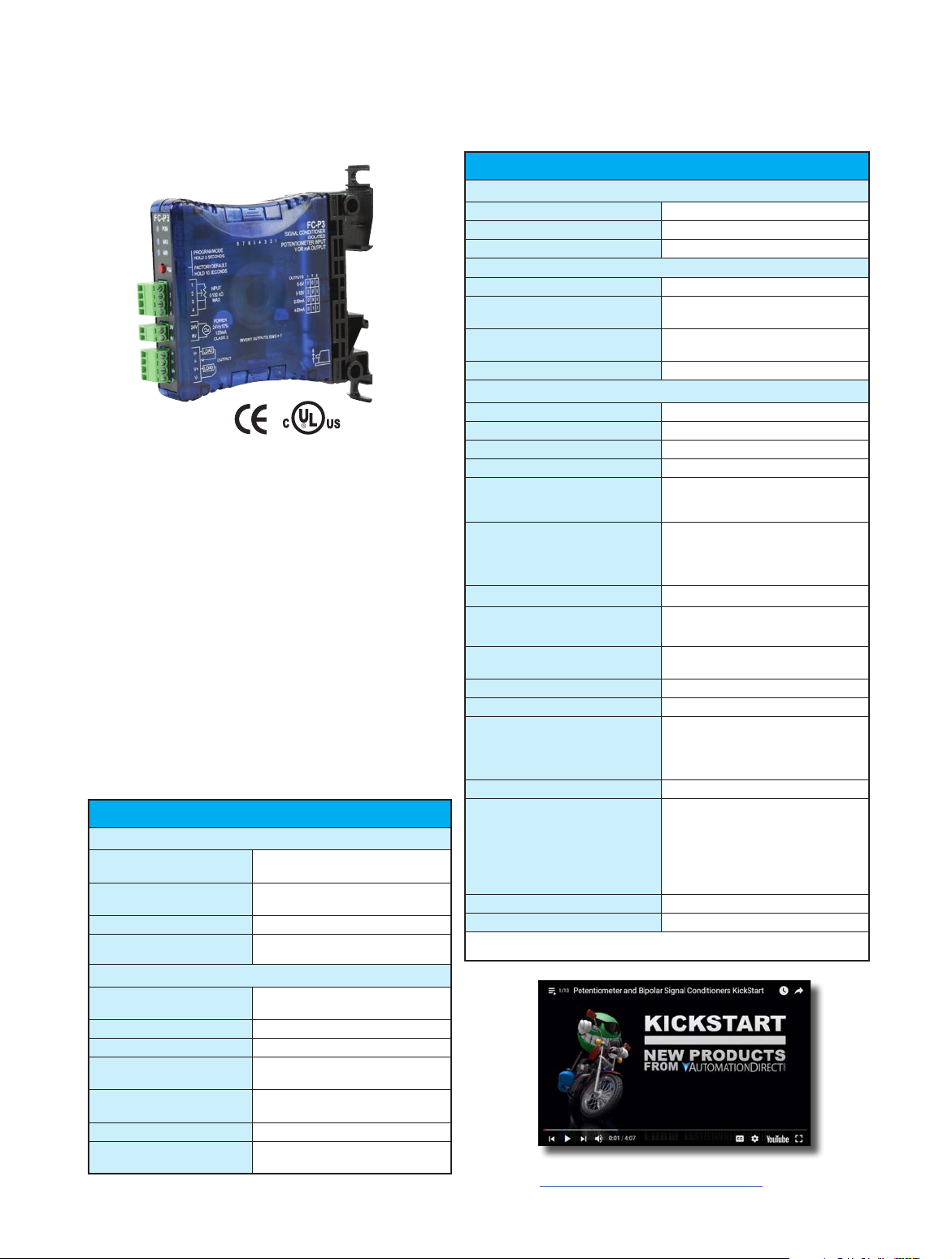
Overview
The FC-P3 is a resistive input to isolated analog output
signal conditioner. The input resistive range (high end resistivity, low end resistivity) is set through the use of a pushbutton programming routine.
The FC-P3 is field configurable for 3-wire potentiometer/slide-wire inputs with end-to-end resistance ranges
from 0-100 ohms to 0-100 kilohms. The input adjustment range can be scaled down to a minimum of
10% of the potentiometer being used. Switch selectable, analog output options include 0-20 mA, 4-20 mA,
0-5V, and 0-10 V. The PGM LED provides an indication of
operating status and is used during the field programming
process.
The MAX and MIN LED’s indicate OVER and
UNDER range status. The module can be 35 mm
DIN rail or side mounted and is UL listed. Power
for the unit is provided by a customer supplied
24 VAC or 24 VDC Class 2 power supply.
Specifications
Input Specifications
Input Ranges
Programmable Range
Minimum
Excitation
External Power Required
Output Ranges
Maximum Output Current
Response Time
Load Impedance
Output Drive
Maximum Inaccuracy
Output Stability and
Repeatability
tPSC-7
Output Specifications
Signal Conditioners
0 - 100 ohms up to 0-100 kilohms,
3-wire potentiometer/slide-wire
Pushbutton Adjustable to 10% of full range of
applied potentiometer
>100 uA @ 2.5VDC
24 VDC ±10% @ 120 mA or 24 VAC ±10% @
120 mA, Class 2
0-5 V, 0-10 V, 0-20 mA, 4-20 mA
(DIP Switch Selectable/Invertable)
21 mA (for mA OUT ONLY)
35 ms for mA Out, 100 ms for V Out
2 kilohm minimum, voltage output
550 ohms maximum current output
Voltage: 10 mA maximum
Current: 21 mA maximum
±0.75% @ 0-60°C, FSO maximum
0.05% FSO maximum
Output Ripple
Output Protection
Inverted Outputs
Field Wiring
Number of Positions
Wire Range
Screw Torque
Accuracy vs. Temperature
Response Time
Power Dissipation within Module
Thermal Dissipation
Surrounding Air Temperature
Storage Temperature
Enclosure Rating
Humidity
Environmental Air
Vibration
Shock
Isolation
Insulation Resistance
Noise Immunity
Weight
Agency Approvals
* In order to comply with UL508, the supplied power must be less than 26 VDC and fused at a
maximum of 3 amps.
Specifications (continued)
Output Specifications (continued)
0.05% of full scale
Outputs short circuit protected
Invert Outputs using DIP Switch 6
Terminal Block Specifications
Removable Screw Terminal Blocks (included)
2 (Dinkle EC350V-02P), 4 (Dinkle EC350V-04P),
4 (Dinkle EC350V-04P)
28-14 AWG solid or stranded conductor;
wire strip length 1/4” (6-7mm)
1.7 inch-pounds (0.19 NM)
General Specifications
±50 PPM of full scale/°C Maximum
35 ms, 100 ms for 0-10V range
3W Maximum
9.42 BTU/hr
0 to 60°C (32 to 140°F)
IEC 60068-2-14 (Test Nb, Thermal Shock)
-20 to 70°C (-4 to 158°F)
IEC 60068-2-1 (Test Ab, Cold)
IEC 60068-2-2 (Test Bb, Dry Heat)
IEC 60068-2-14 (Test Na, Thermal Shock)
IP20
5 to 95% (non-condensing)
IEC 60068-2-30 (Test Db, Damp Heat)
No corrosive gases permitted
(EN61131-2 pollution degree 1)
MIL STD 810C 514.2
MIL STD 810C 516.2
1500 VDC Input to Output
1000 VDC Power to Input
1000 VDC Power to Output
applied for 1 second (100% tested)
>10 M ohm @ 500 VDC
NEMA ICS3-304
IEC 61000-4-2 (ESD)
Impulse 1000 V @ 1µS pulse
IEC 6100-4-4 (FTB)
RFI, (145 MHz, 440 MHz 5W @ 15 cm)
IEC 61000-4-3 (RFI)
0.25 lbs
UL508*, File Number: E157382, CE
Click on the above thumbnail or go to
https://www.automationdirect.com/VID-PS-0003 for a short
introductory video for the FC Series Signal Conditioners.
1-800-633-0405
Page 8
For the latest prices, please check AutomationDirect.com.
FC-P3 Application and Dimensions
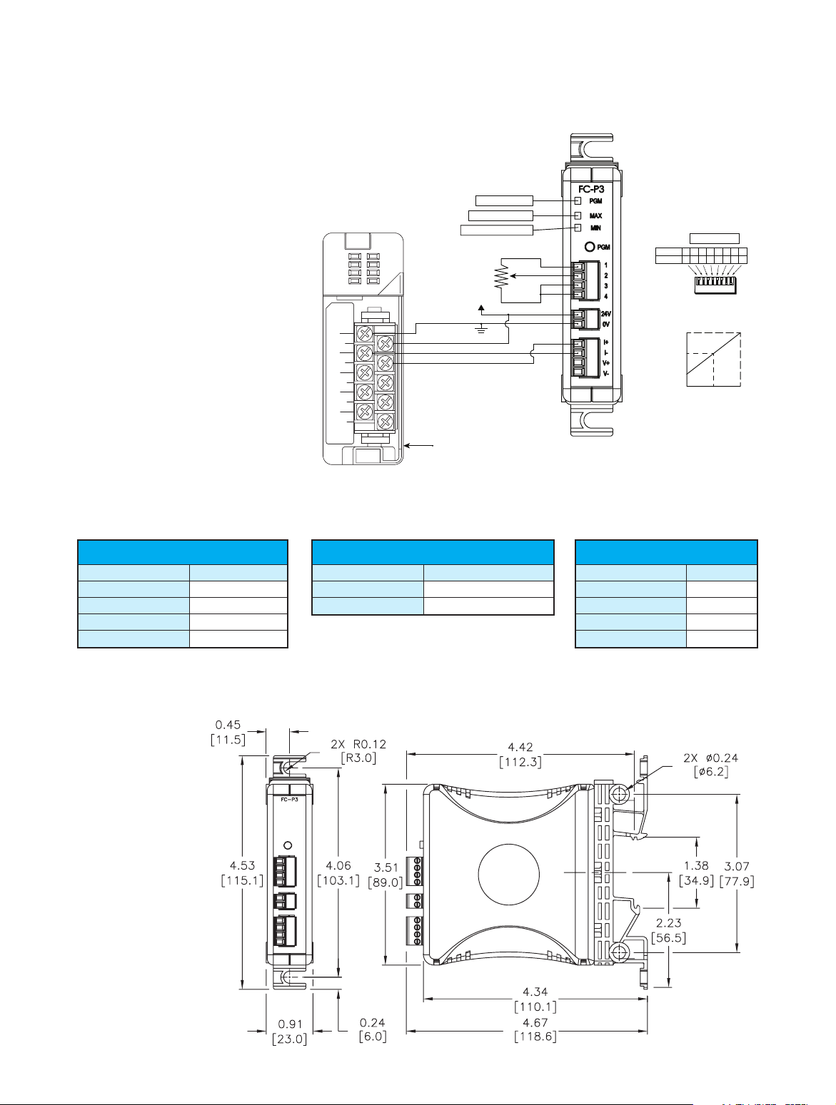
Application
Use the FC-P3 to eliminate the
challenge of getting a variable set by a
machine operator into the PLC. Using
the FC-P3 to convert the resistive signal
from a 10 kilohm potentiometer to a
4-20 mA signal that can be used by a
PLC is simple.
IN ANALOG
F2-- 04AD--1
18-- 26.4VDC
80mA
ANALOG IN
4--20mA
0V
+24V
CH1--
CH1+
CH2--
CH2+
CH1-
CH1+
CH2-
CH2+
F2-- 04AD1
4CH
RUN/CAL LED
OVER Range LED
UNDER Range LED
10 kilohm Pot
24V
4-20 mA
PLC Analog Input Module
NOTE: Pot must be wired so that the minimum Pot
resistance is between Input Terminals 1 & 2.
4-20 mA / 2-10 V Output Ranges
Input DIP 1 2 3 4 5 6 7 8
Setup 0 0 0 0 0 0 1 1
OUT
(mA)
Set For
DIP Switch
12345678
DIP Switches
20
12
4
05
INPUT
(kΩ )
10
Wiring Connections
Input Terminal Block
Faceplate Label Description
1
2
3
4
NOTE: Pot must be wired so that the minimum Pot
resistance is between Input Terminals 1 & 2.
Pot End Terminal
Pot Wiper
Pot End Terminal
Shield Connection
Dimensions
inches [mm]
External Power Terminal Block
Faceplate Label Description
24 V
0V
24 VDC or 24 VAC ±10%, Class 2
0V
Output Terminal Block
Faceplate Label Description
I+
I-
V+
V-
Current
Current
Voltage
Voltage
tPSC-8
Signal Conditioners
1-800-633-0405
Page 9
For the latest prices, please check AutomationDirect.com.
FC Series Accessories
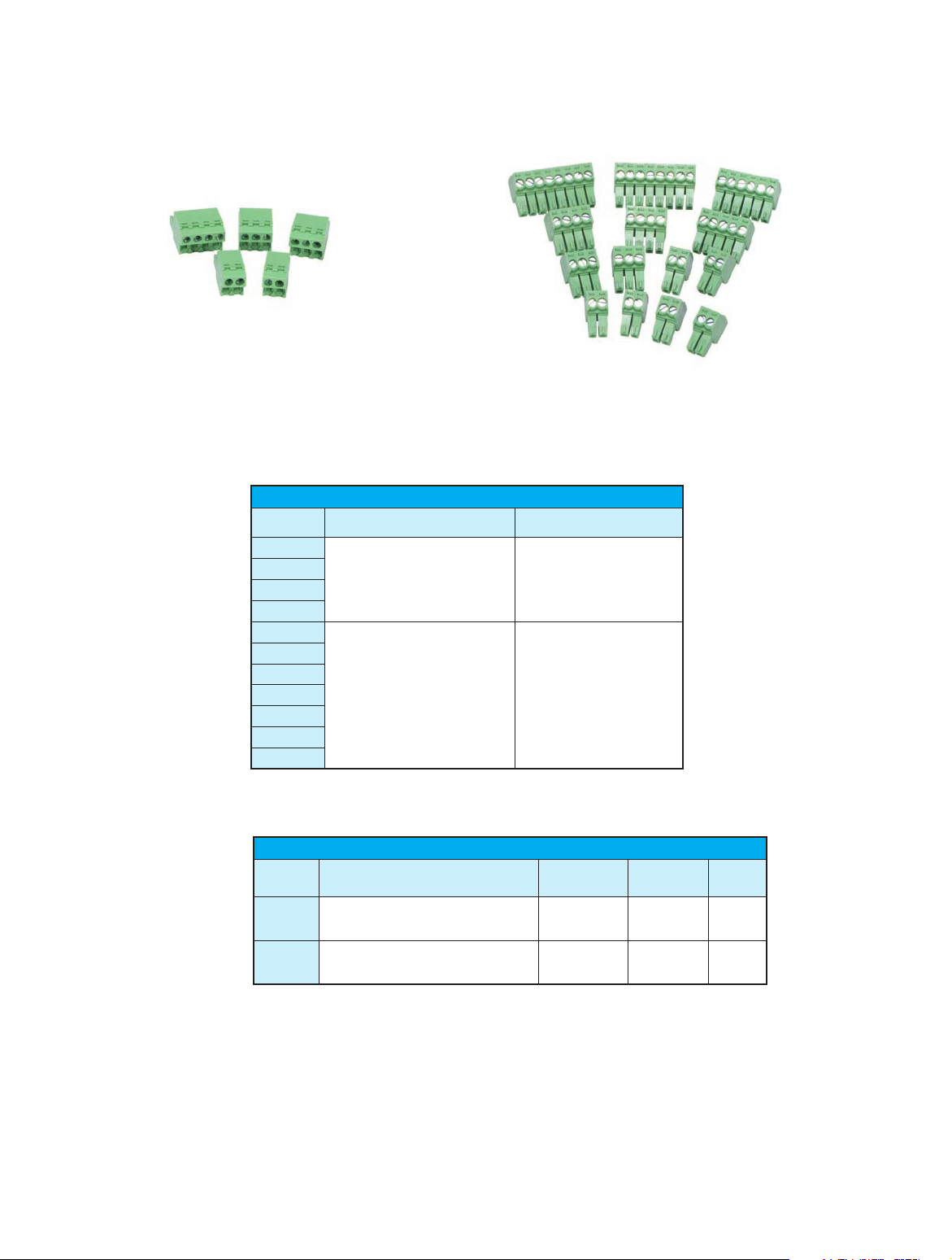
FC-5MM
FC-35MM
Description
Universal terminal block replacements for the FC Series signal conditioners. Each packcage includes enough terminal blocks to
replace all the terminal blocks on any FC Series signal conditioner according to the following table:
FC Series Terminal Blocks
FC Series
Model
FC-11
FC-33
FC-R1
FC-T1
FC-ISO-C
FC-ISO-D
FC-B34
FC-35B
FC-P3
FC-3RLY2
FC-3RLY4
Terminal Block Replacement
Part Number
FC-5MM
FC-35MM
Package Includes
(2) 2-pole blocks
(2) 3-pole blocks
(1) 4-pole blocks
(6) 2-pole blocks
(2) 3-pole blocks
(2) 4-pole blocks
(1) 5-pole blocks
(1) 6-pole blocks
(2) 8-pole blocks
tPSC-27
Note: Depending on the model, some terminal blocks in the package may be unused.
Signal Conditioners
Part No. Description
FC-5MM
FC-35MM
Terminal block, replacement, 5mm. Package of 5. For
use with FC Series signal conditioners.
Terminal block, replacement, 3.5mm. Package of 14.
For use with FC Series signal conditioners.
Universal Signal Conditioners
Rated Torque
(N·m)
0.5 0.1 $12.00
0.2 0.1 $22.50
Weight (Lbs) Price
1-800-633-0405
 Loading...