

Page 1

Congratulations !
Model WP-80
You have purchased the latest in Handheld pH-mV-Temperature
instrumentation. We trust that your new WP-80 will give you many years
of reliable service.
The WP-80 is a breeze to operate. This manual has been designed to
help you get started, and also contains some handy application tips. If at
any stage you require assistance, please contact either your local TPS
representative or the TPS factory in Brisbane.
The manual is divided into the following sections:
1. Table of Contents
Each major section of the handbook is clearly listed. Sub-sections
have also been included to enable you to find the information you
need at a glance.
2. Introduction
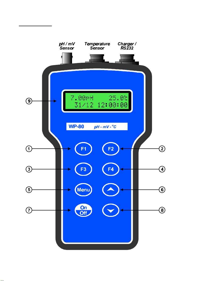
The introduction has a diagram and explanation of the display and
controls of the WP-80. It also contains a full listing of all of the items
that you should have received with your WP-80. Please take the time
to read this section, as it explains some of items that are mentioned
in subsequent sections.
3. Main Section
The main section of the handbook provides complete details of the
WP-80, including operating modes, calibration, troubleshooting,
specifications, and warranty terms.
4. Appendices
Appendices containing background information and application notes
are provided at the back of this manual.
pH-mV-Temp. Meter
Version : 3.51
Date : 02/07/2003
Author : MS
Page 2

Page 1
TPS Pty Ltd
ABN 30 009 773 371
4 Jamberoo Street
Springwood, Brisbane,
Australia, 4127
Phone : (07) 32 900 400
International : 61 7 32 900 400
Fax : (07) 3808 4871
International : 61 7 3808 4871
Email : [email protected]
Web : www.tps.com.au
Page 3

Page 2
Contents
1. Introduction .....................................................................................4
1.1 WP-80 Display and Controls............................................................... 4
1.2 Unpacking Information ........................................................................ 6
1.3 Specifications..................................................................................... 7
2. WP-80 Menu Structure....................................................................9
3. Operating Modes...........................................................................10
3.1 Selecting pH, mV or Relative mV Mode ............................................ 10
4. pH Calibration................................................................................12
4.1 Calibration Procedure....................................................................... 12
4.2 Calibration Notes.............................................................................. 14
4.3 Calibration Messages....................................................................... 14
5. mV Calibration...............................................................................15
6. Relative mV Calibration ................................................................15
6.1 Notes ............................................................................................... 16
7. Temperature Calibration...............................................................17
7.1 Calibration Procedure....................................................................... 17
7.2 Calibration Notes.............................................................................. 17
7.3 Calibration Messages....................................................................... 18
7.4 Manual Temperature Setting............................................................. 19
8. Good Laboratory Practices (GLP)................................................20
8.1 To recall GLP information on the display........................................... 20
8.2 Failed Calibration.............................................................................. 21
8.3 Printing GLP Information to the RS232 Port...................................... 21
8.4 Instrument Serial Number................................................................. 22
8.5 Additional GLP Features................................................................... 22
9. Notepad Function..........................................................................23
9.1 Recording Readings into the Notepad............................................... 23
9.2 Recalling Records from the Notepad................................................. 23
9.3 Erasing Records from the Notepad................................................... 24
9.4 Printing Records from the Notepad to the RS232 Port....................... 24
10. Automatic Datalogging..............................................................25
Page 4

Page 3
11. RS232 Port.................................................................................27
11.1 Setting the Baud Rate ................................................................... 27
11.2 Sending Readings to the RS232 Port............................................ 27
11.3 RS232 Configuration..................................................................... 27
11.4 Communication and Statistical Software ....................................... 27
11.5 Commands................................................................................... 28
11.6 Data Format ................................................................................. 29
12. Battery Saver Function.............................................................31
13. Clock Function ..........................................................................34
13.1 Setting the Clock........................................................................... 34
13.2 Displaying or Hiding the Clock ...................................................... 34
14. Selecting Buffers for Auto Buffer Recognition .......................35
15. Initialising the WP-80 ................................................................36
16. Troubleshooting........................................................................37
16.1 General Errors.............................................................................. 37
16.2 pH and mV Troubleshooting.......................................................... 38
16.3 Temperature Troubleshooting....................................................... 39
17. Warranty ....................................................................................40
18. Appendices................................................................................42
18.1 pH Electrode Fundamentals .......................................................... 42
18.2 Checking the reference junction of a pH electrode......................... 44
18.3 Determining if an instrument or electrode is faulty ......................... 45
18.4 Instrument firmware version number. ............................................ 45
Page 5
Page 4
1. Introduction
1.1 WP-80 Display and Controls
Page 6

Page 5
Press to record readings into memory. See section 9.1.
Also used to select primary and secondary buffers for automatic
buffer recognition. See section 14.
Press to show or hide the date and time. See section 13.2.
Press to start or stop automatic logging. See section 10.
Alternatively, press to transmit current reading plus date and time to
the RS232 port (optional) See section 11.2.
Press to zero relative mV, when relative mV mode is selected. See
section 6.
Press to access the user-friendly menu system which makes the
WP-80 a breeze to operate.
and
The and keys are used when calibrating temperature readout
(section 7), setting manual temperature compensation (section 7.4),
setting the clock (section 13.1), setting the automatic logging period
(section 10), and displaying GLP information (section 8.1).
The key is also used to initialise the WP-80 at turn-on. See
section 15.
Switches the WP-80 on and off.
Display
32 character alpha-numeric display with user-friendly menu and
prompting system. Shows pH/mV and temperature simultaneously.
Date and time can also be displayed.
Page 7

Page 6
1.2 Unpacking Information
Before using your new WP-80, please check that the following
accessories have been included:
Part No
1. WP-80 pH-mV-Temperature Instrument.................................121109
2. Combination pH Sensor.........................................................121207
3. Temperature/ATC Sensor......................................................121247
4. pH6.88 Buffer, 200mL............................................................121306
5. pH4.00 Buffer, 200mL............................................................121381
6. Battery charger ......................................................................130037
7. WP-80 Handbook...................................................................130050
Options that may have been ordered with your WP-80:
1. RS232 Serial Interface Option (includes cable).....................130039
2. Communication software for Microsoft Windows 95..............130086
and all later versions
3. Hard Carry Case...................................................................130059
4. Battery charger lead for 12V cigarette lighter socket.............130046
5. Battery charger lead for 12V DC, with battery clips...............130052
6. Solar Panel...........................................................................130012
Other spares:
1. 6V NiMH Battery....................................................................130038
2. RS232 Interface Cable...........................................................130041
Page 8

Page 7
1.3 Specifications
pH
Range.......................................0 to 14.00 pH
Resolution...............................0.01 pH
Accuracy..................................±0.01 pH
mV
Range.......................................0 to ±500.0 and 0 to ±1500 mV (auto-
ranging)
Resolution...............................0.15 and 1 mV
Accuracy..................................±0.3 and ±1 mV
Temperature
Range.......................................-10.0 to +120.0 oC
Resolution...............................0.1 oC
Accuracy..................................±0.2 oC
General Specifications
Temperature Compensation .....0 to 100.0 oC, automatic or manual
pH Asymmetry Range...............-1.00 to 1.00 pH
pH Slope Range........................85.0 to 105.0%
Memory.....................................150 readings including date and time
Automatic Logging....................User-set for one reading every 1 to 90
seconds, minutes or hours.
RS232 Output (optional) ...........300, 1200 & 9600 baud. 8 bits, no parity,
1 stop bit, XON/XOFF Protocol.
Clock.........................................Calendar clock displays date, month,
hours, minutes & seconds.
Year is recorded in memory and
transmitted to optional RS232 port, but is
not displayed.
Battery Saver............................On : Auto switch-off after 5 minutes
Off : Continuous use
Bar Graph display of battery charge level.
Readout of battery voltage available for
troubleshooting.
Page 9

Page 8
Good Laboratory Practices.......Date, Time and Value of last asymmetry
and last slope calibration are stored, and
can be recalled or sent to the optional
RS232 port at any time.
Input Impedance....................... >3 x 10¹² Ω
Power.......................................6V NiMH Rechargeable Battery for
approx 50 hours operation.
Dimensions...............................187 x 110 x 51 mm
Mass.........................................Instrument only : Approx 440g
Full Kit : Approx 1.7kg
Environment.............................Temperature : 0 to 45 oC
Humidity : 0 to 90 % R.H.
Page 10

Page 9
2. WP-80 Menu Structure
A detailed breakdown of the menu system of the WP-80 is shown below.
This diagram provides a quick reference for the menu functions available
for the WP-80.
F1:Cal.
→
F2:Temp
F2:Erase
F2:Notepad
→
F1:pH (available when in pH mode)
→
F1:Recall
→
F3:Print *
F4:Prog.
F2:Sec
→
F1:Min
F3:Hr
F2:mV
F3:Mode
→
F1:pH.
→
↑↓:Set Period
F3:Rel mV
→
F4:Setup
→
F1:Batt
F1:OFF
→
(Disable Battery
Saver)
F2:ON
(Enable Battery
Saver)
F2:Clock
F3:GLP
F3:Print *
→
F1:Recall
F4:Baud *
→
F1:300
F2:1200
F3:9600
* These items available when the optional RS232 port is fitted.
Page 11
Page 10
3. Operating Modes
3.1 Selecting pH, mV or Relative mV Mode
To select pH, mV or Relative mV mode…
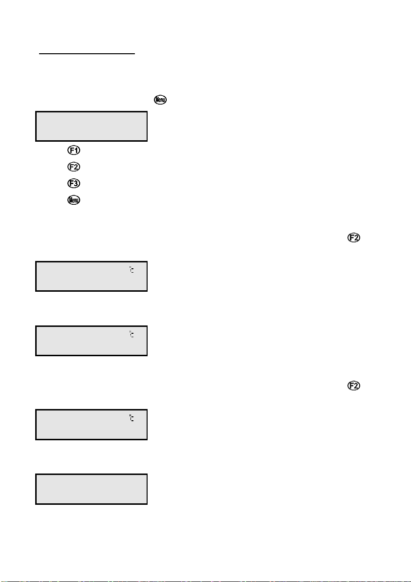
1. Select the Mode menu ( , then →→ F3:Mode)…
F1:pH F2:mV
F3:Rel mV
2. Press to select pH mode.
Press to select mV mode.
Press to select Relative mV mode.
Press to quit and retain the current selection.
3.1.1 pH Mode
Displays pH and Temperature readings simultaneously. Press to
show or hide the date and time. For example…
7.00pH 25.0
31/12 12:00:00
If the temperature probe is unplugged, the manual temperature setting
is displayed with 1oC resolution. For example…
7.00pH Man 25
31/12 12:00:00
3.1.2 mV Mode
Displays mV and Temperature readings simultaneously. Press to
show or hide the date and time. For example…
1000mV 25.0
31/12 12:00:00
If the temperature probe is unplugged, no temperature value is
displayed…
1000mV
31/12 12:00:00
Page 12
Page 11
3.1.3 Relative mV Mode
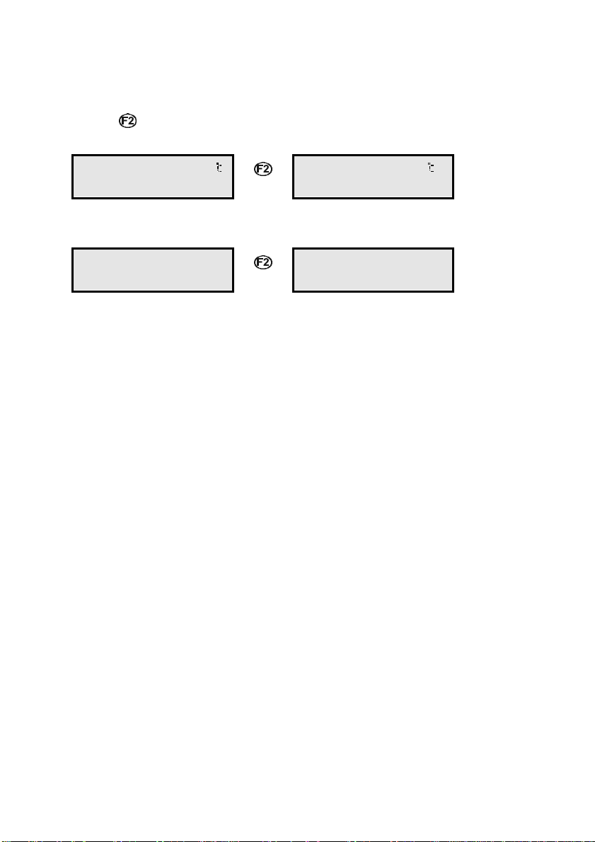
Displays Relative mV and Temperature readings simultaneously.
Press to alternatively show absolute mV or the date and time. For
example…
1000mVR 25.0
660mV F4:Zeros
If the temperature probe is unplugged, no temperature value is
ÖÖ
1000mVR 25.0
31/12 12:00:00
displayed…
1000mVR
660mV F4:Zeros
Notes
ÖÖ
1000mVR
31/12 12:00:00
1. Temperature compensation does not apply in mV mode.
2. The decimal point is replaced by a ∗∗ if a pH or Temperature
calibration has failed (sections 4.1, and 7.1) if the unit is initialised
(section 15), or if the unit has lost its factory calibration (section 16.1).
Page 13

Page 12
4. pH Calibration
A “ ∗ ” in place of the decimal point indicates that the pH readout is not
calibrated, or a past calibration has failed. The “ ∗ ” will be removed once
a full two-point pH calibration has been successfully performed.
4.1 Calibration Procedure
1. Plug the pH sensor into the pH/mV socket and the temperature
sensor into the Temperature socket.
2. Switch the meter on.
3. Ensure that you are using buffers which have been selected for
automatic buffer recognition. See section 14 for a detailed
explanation.
4. Select pH Mode ( →→ F3:Mode →→ F1:pH).
5. Ensure that temperature has already been calibrated, or manually set
(see sections 7.1 and 7.4). NOTE: If the decimal point in the
temperature reading is shown by a " ∗∗ ", then the temperature readout
is not calibrated.
6. Remove the wetting cap from the pH sensor.
7. Rinse the pH and Temperature sensors in distilled water and blot
them dry.
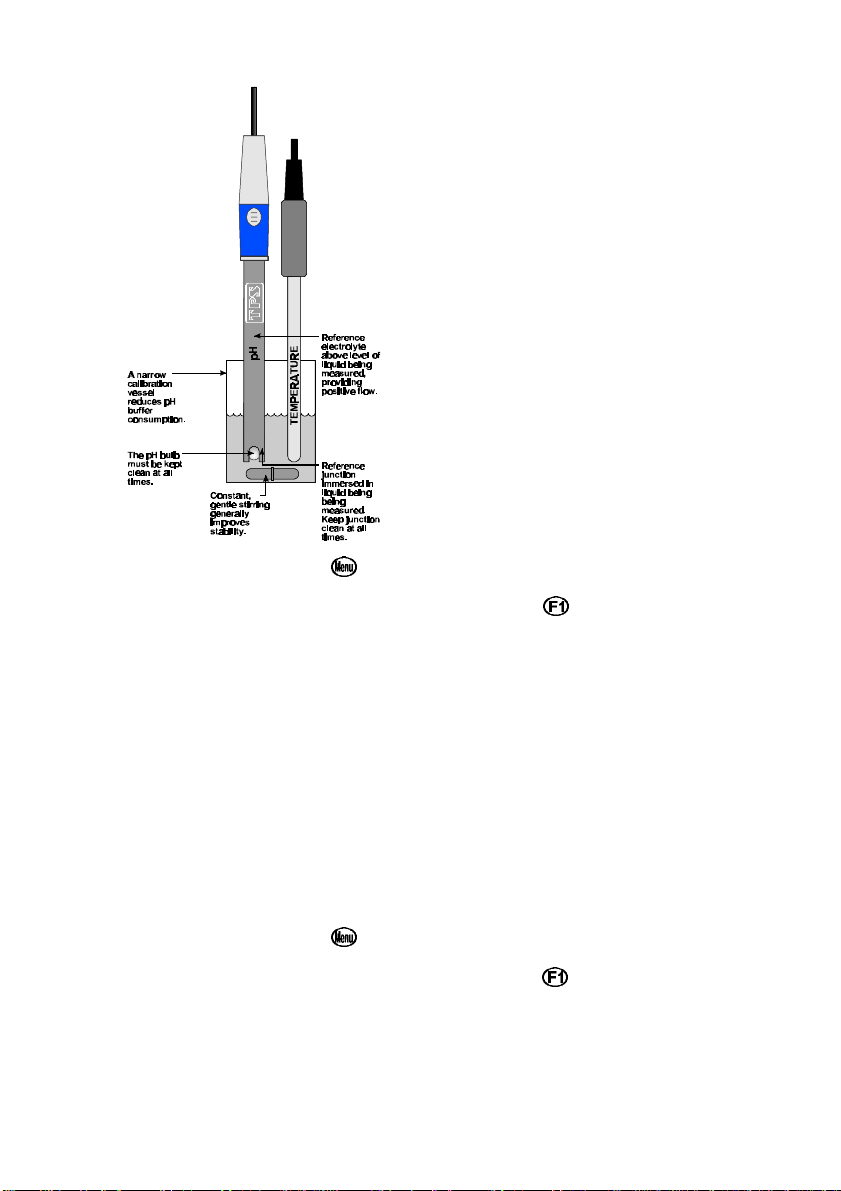
8. Place both electrodes into a small sample of pH6.88 (or pH7.00)
buffer, so that the bulb and reference junction are both covered, as
per the diagram over the page.
DO NOT place the electrodes directly into the buffer bottle.
Page 14
Page 13
9. Select pH Calibration ( →→ F1:Cal. →→ F1:pH).
10. When the reading has stabilised, press the key to calibrate. If a 1
point calibration has been performed, the " ∗∗ " will not be removed
until a full 2 point calibration has been performed.
11. Rinse the pH and Temperature electrodes in distilled water and blot
them dry.
12. Place both sensors into a small sample of pH4.00, pH9.23 or pH10.00
Buffer, so that the bulb and reference junction are both covered, as
per the diagram in step 8, above. DO NOT place the electrodes
directly into the buffer bottle.
NOTE: pH9.23 buffer is highly unstable. Avoid using this buffer if
possible. Discard immediately after use.
13. Select pH Calibration ( →→ F1:Cal. →→ F1:pH).
14. When the reading has stabilised, press the key to calibrate. The "
∗ " will now be replaced by a decimal point, if calibration was
successful.
15. The WP-80 is calibrated and ready for use in this mode. Discard the
used samples of buffer.
Page 15

Page 14
4.2 Calibration Notes
1. A 1-point calibration should be performed at least weekly. In
applications where the electrode junction can become blocked, such
as dairy products, mining slurries etc, a 1-point calibration may have to
be done daily.
2. A full 2-point calibration should be performed at least monthly. Of
course, more frequent calibration will result in greater confidence in
results.
3. All calibration information is retained in memory when the WP-80 is
switched off, even when the battery is removed. This information can
be recalled or printed later using the GLP function (see section 8).
4. The WP-80 displays the value of the pH buffer to which it will attempt
to calibrate. Ensure that the buffer value displayed corresponds to the
buffer that you are using.
4.3 Calibration Messages
1. If a 1-point calibration has been successfully performed, the WP-80 will
display the following message, and the asymmetry of the electrode.
For example…
1 Point Cal.OK
Asy= 0.10pH
2. If a 1-point calibration has failed, the WP-80 will display the following
message, and the failed asymmetry value of the electrode. For
example:
1 Point Cal.Fail
Asy= 1.50pH Hi
or :
1 Point Cal.Fail
Asy=-1.50pH Lo
3. If a 2-point calibration has been successfully performed, the WP-80 will
display the following message, and the asymmetry and slope of the
electrode. For example…
2 Point Cal.OK
Asy= 0.10pH
then :
2 Point Cal.OK
Slope=100.0%
4. If a 2-point calibration has failed, the WP-80 will display the following
message, and the failed slope value of the electrode. For example…
2 Point Cal.Fail
Slope=130.0% Hi
or :
2 Point Cal.Fail
Slope= 70.0% Lo
Page 16
Page 15
5. mV Calibration
The mV section is factory calibrated. There is no user-calibration facility
for this mode.
6. Relative mV Calibration
Select Relative mV mode when measurements relative to a known
standard are required. Calibration of the Relative mV mode is simply a
matter of zeroing the reading when the sensor is in the known standard.
1. Plug the Redox sensor into the pH/mV socket. Temperature
compensation is not applied in Relative mV mode, so the temperature
sensor does not need to be connected.
2. Switch the meter on.
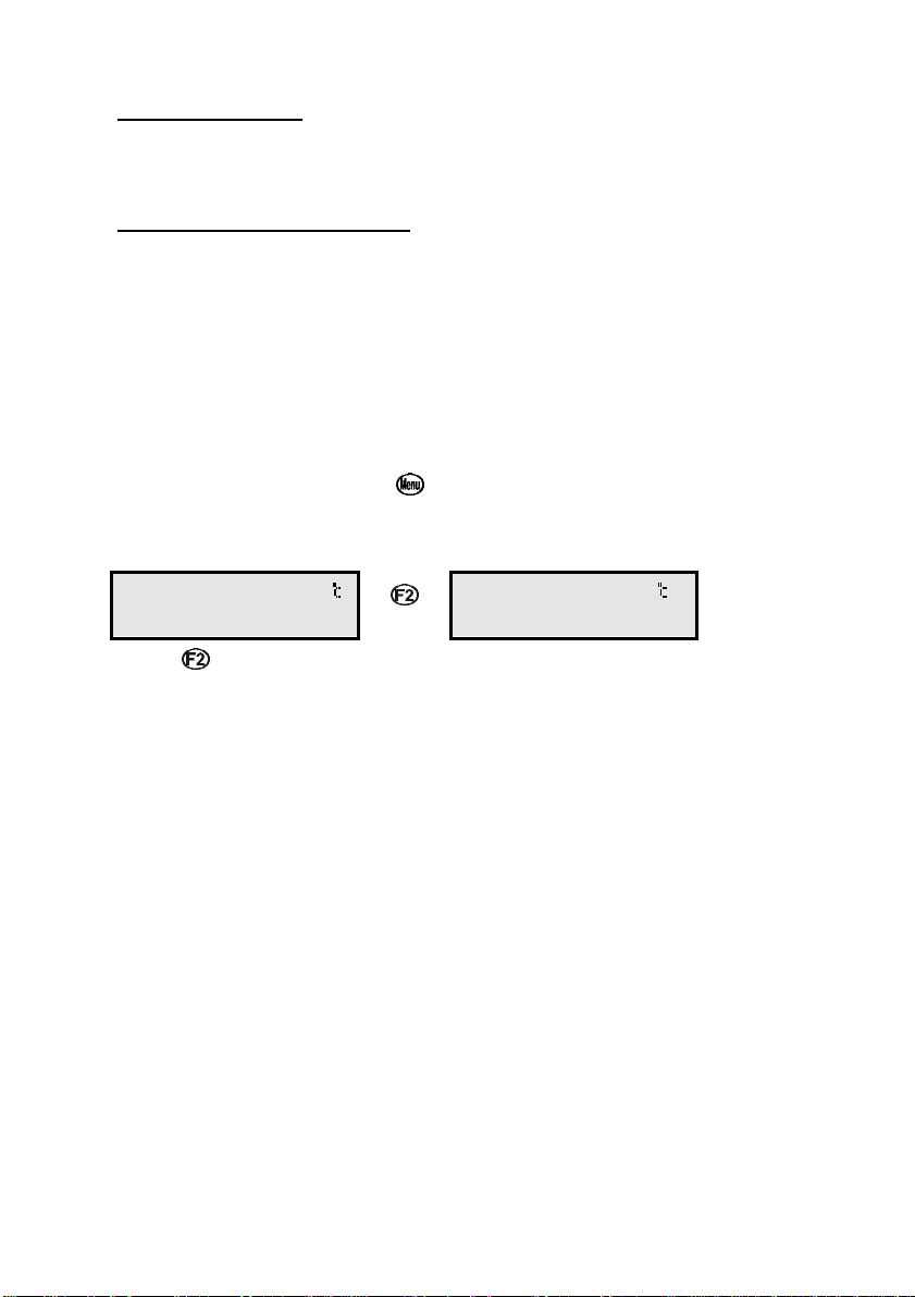
3. Select Relative mV Mode ( →→ F3:Mode →→ F3:Rel mV).
The display should now be showing Relative mV on the top line with
absolute mV or date and time on the bottom line. For example…
1000mVR 25.0
660mV F4:Zeros
Press to alternate between absolute mV or the clock on the bottom
Ö
1000mVR 25.0
31/12 12:00:00
line.
4. Remove the wetting cap from the Redox sensor.
5. Rinse the sensor in distilled water and blot dry.
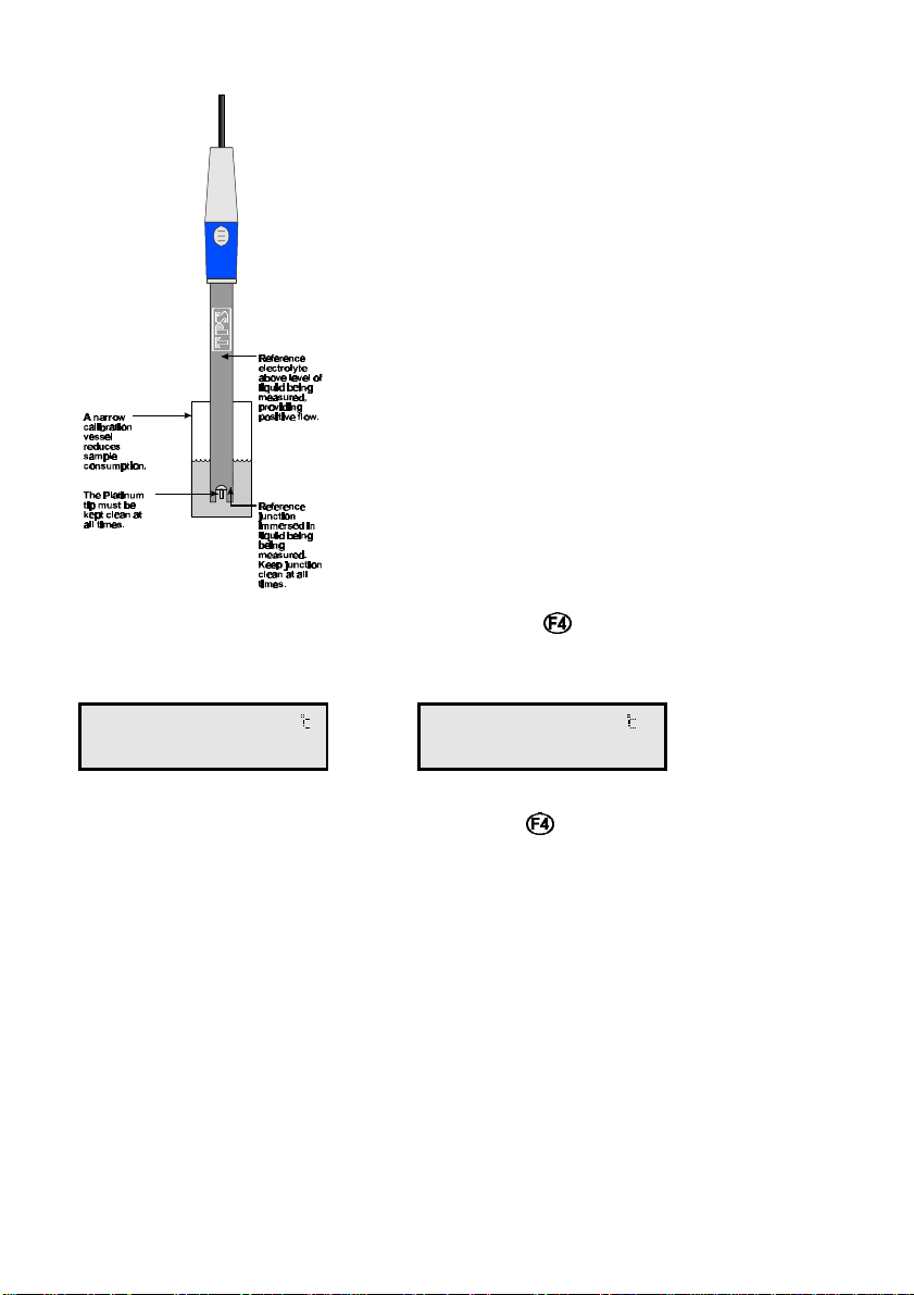
6. Place the Redox sensor into a sample of the known standard. Ensure
that the platinum tip and reference junction are both covered, as per
the diagram over the page.
Page 17
Page 16
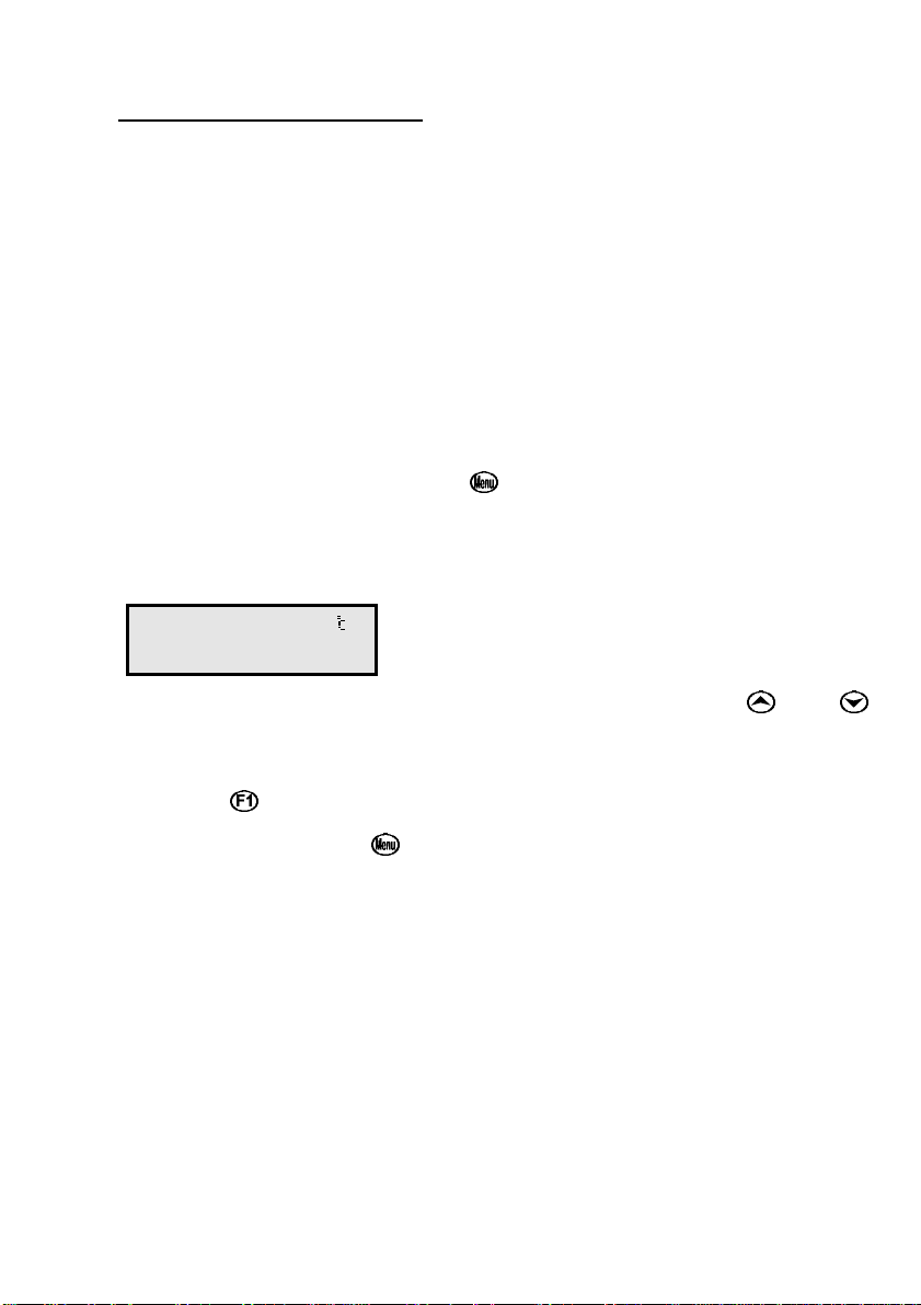
7. When the reading has stabilised, press the key to zero the Relative
mV reading. The Relative mV reading will now be zero, and the
absolute mV reading will remain unchanged. For example…
0mVR 25.0
660mV F4:Zeros
8. The WP-80 Relative mV mode is now zeroed and is ready for use. The
or:
0mVR 25.0
31/12 12:00:00
readout can be re-zeroed by pressing the key whenever required.
6.1 Notes
1. The Relative mV offset is retained in memory when the WP-80 is
switched off, even when the battery is removed.
2. The Relative mV zero is reset when leaving Relative mV mode (see
section 3)
Page 18
Page 17
7. Temperature Calibration
A “ ∗ ” in place of the decimal point indicates that the Temperature
readout is not calibrated, or a past calibration has failed. The “ ∗ ” will be
removed once Temperature has been successfully calibrated.
7.1 Calibration Procedure
1. Plug the temperature sensor into the Temperature socket.
2. Switch the meter on.
3. Place the sensor into a beaker of room temperature water, alongside
a good quality mercury thermometer. Stir the probe and the
thermometer gently to ensure an even temperature throughout the
beaker.
4. Select Temperature Calibration ( →→ F1:Cal. →→ F2:Temp).
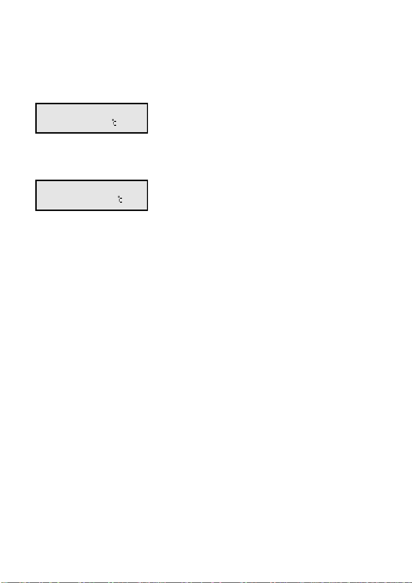
5. The reading from the probe is now displayed on the right of the
display, and the value you are going to set is shown on the left. For
example…
> 25.0< 20*0
↑↑↓↓:Set F1:Cal.
6. When the reading on the right has stabilised, press the and
keys until the reading on the left shows the same temperature as the
mercury thermometer.
7. Press the key to calibrate the temperature readout.
Alternatively, press the key to abort temperature calibration.
7.2 Calibration Notes
1. Temperature calibration information is retained in memory when the
WP-80 is switched off, even when the battery is removed. This
information can be recalled later using the GLP function (see section
8).
2. Temperature does not need to be recalibrated unless the
Temperature probe is replaced or the meter is initialised.
Page 19
Page 18
7.3 Calibration Messages
1. If a temperature calibration has been successfully performed, the
WP-80 will display the following message and the offset value of the
probe. For example:
Calibrate OK
Offset= 1.0
2. If a temperature calibration has failed, the WP-80 will display the
following message, and the failed offset value of the probe. For
example…
Calibrate Failed
Offset= 10.5
Page 20
Page 19
7.4 Manual Temperature Setting
If the temperature sensor is not connected, the temperature of the sample
solution must be set manually for accurate pH measurements. A separate
thermometer will be required for this.
1. Switch the meter on.
2. Measure the temperature of the sample.
3. Select Temperature Calibration ( →→ F1:Cal. →→ F2:Temp).
4. The current temperature setting is now displayed. For example…
> 25.0< Man Temp
↑↑↓↓:Set F1:Save
5. Press the and keys until the display shows the temperature of
the sample.
6. Press the key to save the temperature value.
Alternatively, press the key to quit and retain the current setting.
Page 21
Page 20
8. Good Laboratory Practices (GLP)
The WP-80 keeps a record of the date and time of the last pH asymmetry,
pH slope and Temperature offset calibrations as part of GLP guidelines.
8.1 To recall GLP information on the display
1. Switch the meter on.
2. Select the GLP menu ( →→ F4:Setup →→ F3:GLP).
3. Select F1:Recall from the menu.
4. The instrument model, firmware version number, and instrument serial
number are displayed, along with a prompt describing how to scroll
through the GLP information. For example…
WP80 V3.5 S1234
↓↓:More ↑↑:Back
5. Press the key to sequentially scroll through the GLP information
for all parameters. Press the key to scroll back to previous data.
The sequence of information displayed is shown below. Press to
abort at any time.
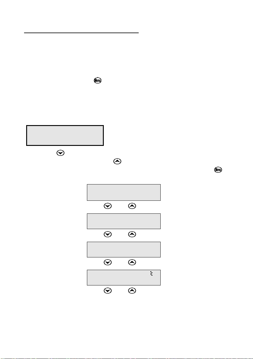
WP80 V3.5 S1234
↓↓:More ↑↑:Back
:↓↓ :↑↑
pH Asy 0.10pH
@ 31/12/02 11:40
:↓↓ :↑↑
pH Slope 100.0%
@ 31/12/02 11:50
:↓↓ :↑↑
Temp Offset 0.1
@ 31/12/02 12:00
:↓↓ :↑↑
Exit
Page 22

Page 21
8.2 Failed Calibration
If calibration has failed, the GLP function will reset the date and time to
zero. The WP-80 still shows the results of the last successful calibration.
For example:
Asy 0.10pH
@ 00/00/00 00:00
Slope 100.0%
@ 00/00/00 00:00
Temp Offset 1.0
@ 00/00/00 00:00
Note that these calibration values are still used if further measurements
are taken without recalibrating.
8.3 Printing GLP Information to the RS232 Port
The GLP information stored in the instrument’s memory can be sent to a
printer or PC via the RS232 port. This function is available only when the
optional RS232 port is fitted.
1. Switch the meter on.
2. Ensure that the WP-80 RS232 cable is connected to the instrument
and to the printer or PC.
3. Send the GLP information to the RS232 port
( →→ F4:Setup →→ F3:GLP →→ F3:Print)
4. The GLP information is sent to the RS232 port in formatted ASCII
text. For example…
WP80 V3.5 S1234 @ 31/12/02 12:00
pH Asy= 0.00pH @ 31/12/02 11:40
pH Slope= 100.0% @ 31/12/02 11:50
Temperature Offset= 1.0oC @ 31/12/02 12:00
ENDS
Page 23

Page 22
8.4 Instrument Serial Number
In case the serial number that is fitted to the rear of the WP-80 is
removed or becomes illegible, it is also available on the WP-80 display.
• The serial number is displayed at turn-on, for example…
WP80 V3.5 S1234
pH mV Temp.
where S1234 is the serial number.
• The serial number is displayed when recalling the GLP information
(section 8.1).
• The serial number is included on the printout of GLP information
(section 8.3).
8.5 Additional GLP Features
Another GLP requirement is to record the date and time of every reading.
The WP-80 does this for you when readings are recorded either with the
Notepad function (section 9) or the Automatic Logging function (section
10).
Page 24
Page 23
9. Notepad Function
9.1 Recording Readings into the Notepad
To record readings into the Notepad memory:
1. Press in normal display mode. The display should now look like
this:
7.00pH 25.0
F1: 1 12:00:00
2. If you now press , the pH, Temperature, Date and Time will be
recorded into the Notepad, and labelled as reading number 1.
3. Repeat steps 1 & 2 as often as required. The maximum number of
readings that can be stored in the Notepad is 150.
9.2 Recalling Records from the Notepad
To recall records from the Notepad onto the WP-80 display:
1. Select the Notepad menu ( →→ F2:Notepad).
2. Select F1:Recall from the menu.
3. Record number 1 is now displayed, for example…
7.00pH 25.0
# 1 F2:Clock
4. Press to alternatively display the date and time or the data for this
record.
Press to move forward through the records.
Press to move backward through the records.
Press and hold the or keys to roll rapidly through the readings.
Page 25
Page 24
9.3 Erasing Records from the Notepad
To erase all records from the Notepad:
1. Select the Notepad menu ( →→ F2:Notepad).
2. Select F2:Erase from the menu.
3. The WP-80 now asks if you are sure that you wish to erase all
records…
Erase, You Sure?
F1:Yes F2:No
4. Press to erase all records from the Notepad.
Press to quit without erasing the records from the Notepad.
9.4 Printing Records from the Notepad to the RS232 Port
This function is only available when the optional RS232 port is fitted.
1. Connect one end of the RS232 cable to the Charger/RS232 socket of
the WP-80. The charger, optional solar panel, or optional car battery
lead can be connected into the spare socket on the cable for long
term use, if required.
2. Connect the other end of the RS232 cable to an RS232 Printer, or to
COM1 or COM2 of a PC.
3. Ensure that the baud rate for the printer or PC and the WP-80 are the
same.
If necessary, alter the baud rate of the WP-80 (see section 11.1).
The WP-80 uses XON/XOFF protocol. Ensure that the printer is set
accordingly.
4. Select the Notepad menu ( →→ F2:Notepad).
5. Select F3:Print from the menu.
Printing starts as soon as is pressed. The display shows the word
“Printing” until printing is completed.
Page 26
Page 25
10. Automatic Datalogging
The WP-80 can automatically log records into the Notepad. First the
logging period must be programmed, then automatic logging can be
started and stopped as required.
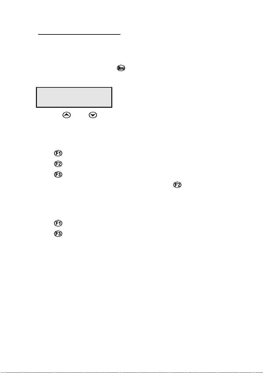
1. Select the Program menu ( →→ F2:Notepad →→ F4:Prog.).
2. The display should now look like this…
>00< F1:Min F2:Sec
↑↑↓↓:Period F3:Hr
3. Use the and keys to set the period at which the WP-80 will
automatically log records.
4. When the logging period has been correctly set, select whether this
period is in minutes, seconds or hours.
Press to save the period as minutes.
Press to save the period as seconds.
Press to save the period as hours.
eg: If the period was set to 05, followed by , then the WP-80 will
automatically log a record every 5 seconds.
5. If the optional RS232 port is fitted, the WP-80 will ask if the records
are to be logged into the Notepad, or sent directly to the RS232 port.
Press to log records into the Notepad (maximum of 150 readings).
Press to send records directly to the RS232 port.
6. The automatic logging function is now programmed, and can be
started and stopped as required.
Continued over the page…
Page 27
Page 26
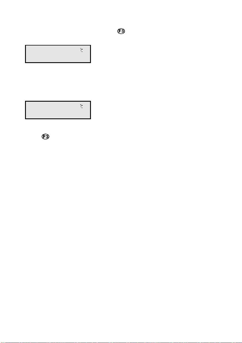
7. To start automatic logging, press in normal display mode.
If the WP-80 is logging into the Notepad, the display will look like this:
7.00pH 25.0
Log# 1 12:00:00
The log number will increment and the WP-80 will beep each time a
reading is recorded.
If the WP-80 is sending records directly to the RS232 port, the display
will look like this…
7.00pH 25.0
Sending 12:00:00
The WP-80 will beep each time a record is sent to the RS232 port.
8. Press to stop automatic logging.
9. Note: The clock must be set before the WP-80 will allow automatic
logging to start. The message “Clock Not Set” is displayed if the
clock is not set.
Page 28
Page 27
11. RS232 Port
This section is applicable if the optional RS232 port is fitted.
11.1 Setting the Baud Rate
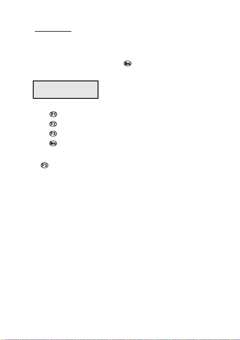
1. Select the RS232 Set-up menu ( →→ F4:Setup →→ F3:Baud).
2. The available baud rates are listed on the display.
F1:300 F2:1200
>F3:9600
The arrow shows the current selection.
3. Press to select 300 baud
Press to select 1200 baud
Press to select 9600 baud.
Press to quit and retain the current setting.
11.2 Sending Readings to the RS232 Port
Press to instantly send readings to the RS232 port whenever the
WP-80 is in normal run mode. This function is disabled if the automatic
logging period is set to greater than zero (see section 10).
Records can be sent directly to the RS232 port rather than stored in
memory during automatic datalogging. See section 10 for details.
11.3 RS232 Configuration
The WP-80 RS232 configuration is 8 bits, No Parity, 1 Stop Bit,
XON/XOFF Protocol.
11.4 Communication and Statistical Software
Communication between the WP-80 and a PC can be handled with any
RS232 communication software. A TPS communication software package
for Windows is optionally available (part number 130086).
Once the data is saved to disk, the next problem is how to use it. The
data sent by the WP-80 is formatted in columns that can be imported by
programs such as Microsoft® Excel® and Lotus 123®.
Help on importing the data into Microsoft® Excel® is provided in section
11.8 and also the “excel.txt” file in the folder where you installed the
WinTPS program.
Page 29

Page 28
11.5 Commands
The following commands can be sent from a PC to the WP-80. Note that
<cr> denotes carriage return and <lf> denotes a line feed.
Action Command Notes
Request current
?D<cr>
data
Request logged data ?R<cr>
Erase logged data ?E<cr>
Request status
?S<cr>
information
Request GLP
?G<cr>
information
Returns the current pH,
Temperature, date and time from
the WP-80. The log number
returned is set to Zero.
Returns all logged records from the
WP-80 memory. The data ends with
the message ENDS<cr>
Erases all logged records from the
WP-80 memory. Returns the
message ERASED<cr> to confirm
that the records have been erased.
Returns the model name, firmware
version number, instrument serial
number and number of logged
readings in memory,
eg: WP80ssssV3.5ssS1234ss150<cr>,
where s are spaces. Note that the
number of logged readings is rightjustified.
Returns all calibration GLP
information, plus the instrument
model and current date (see section
11.6 for data format and
handshaking).
Page 30

Page 29
11.6 Data Format
Data is returned to the RS232 Port by the WP-80 in the following format.
A “•” shown anywhere in this section denotes one space.
LLLLssPPPPPPuuussTTTTTTuuussdd/mm/yysshh:mm:ss
LLLL is the Log Number. Maximum 4 characters, right
justified. The WP-80 sends a Zero for instant readings
(section 11.2)
PPPPPP is pH/mV data. 6 characters, right justified.
uuu is the pH/mV unit description, which can be any of the
following…
pH•
mV•
mVR
TTTTTT is Temperature data, 6 characters, right justified.
uuu is the Temperature unit description, which can be either
of the following…
oC•
oCm
dd/mm/yy is the date, month and year data.
hh:mm:ss is the hours, minutes and seconds data.
When requested by a PC with the ?D or ?R commands (section 11.5), the
data is terminated with a carriage return.
When the data is sent by the WP-80 using the Print function (section 9.4)
or the Send function (section 11.2) the data ends with a carriage return
and a line feed.
for pH readout.
for Millivolts readout.
for Relative Millivolts readout.
for real Temperature data.
for manual Temperature
compensation values.
Page 31

Page 30
11.7 GLP Data Format
GLP information is returned as 4 lines terminated by a carriage return.
When using the “?G” command (section 11.5), the computer must
respond with a character after receiving each line. For example…
WP80 V3.5 S1234 @ 31/12/02 12:00
pH Asy= 0.00pH @ 31/12/02 11:25
pH Slope= 100.0% @ 31/12/02 11:30
Temperature Offset= 1.0oC @ 21/12/02 11:35
ENDS
Page 32
Page 31
11.8 Importing Data into Microsoft Excel
The following procedure details the method for importing a WP-80 text
data file into Microsoft Excel.
1. Start Microsoft Excel and select File → Open
2. In the “Files of type:” pull-down box, choose “Text Files (*prn; *.txt;
*.csv)”.
3. Navigate to the folder where your data file is stored and double-click
it to start the Text Import Wizard.
Note: The default data folder for the WinTPS software is “C:\My
Documents\WinTPS”.
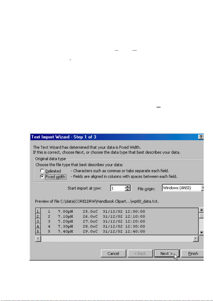
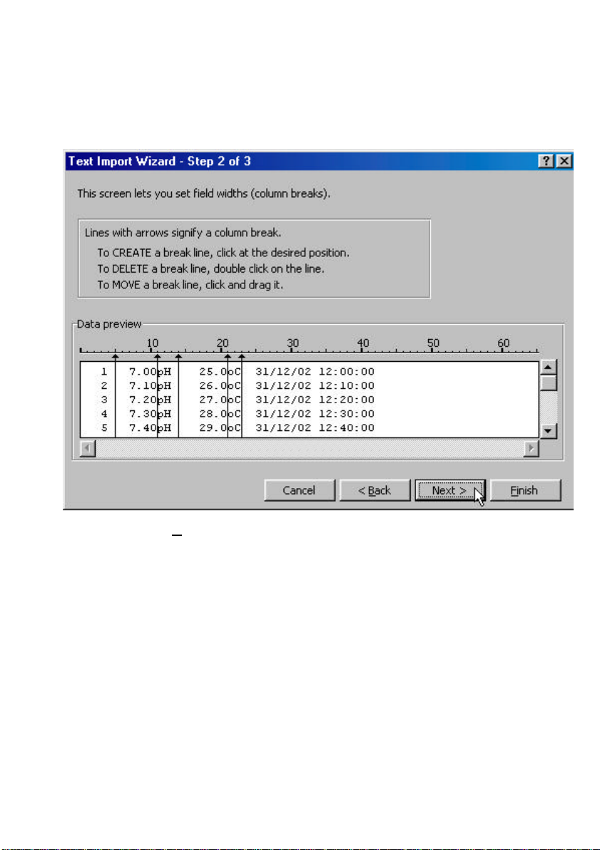
4. In step 1 of the Text Import Wizard select “Fixed width”, as per the
sample screen below, then press “Next >”.
Note that the data column headers in the first row appear only when
the data is downloaded using the WinTPS software.
Continued over the page…
Page 33
Page 32
5. Step 2 of the Text Import Wizard allows you to select the points at
which each data field will break into a new column. The sample
screens below show where TPS recommends the breaks be inserted.
Press “Next >” after the column breaks have been inserted.
6. Simply press “Finish” at step 3 of the Text Import Wizard. TPS
recommends that the data format for each column be set once the
data is in spreadsheet format.
For help on formatting the data columns, charting, graphing or other
operations please consult the Microsoft Excel help file. Alternatively
please contact TPS and we will try to provide further assistance.
Page 34
Page 33
12. Battery Saver Function
The WP-80 is equipped with a battery saver function. If no button has
been pressed for five minutes, the unit beeps and flashes the display for
20 seconds, and then shuts off. This function can be switched off for
continuous use.
To enable or disable the battery saver function:
1. Switch the meter on.
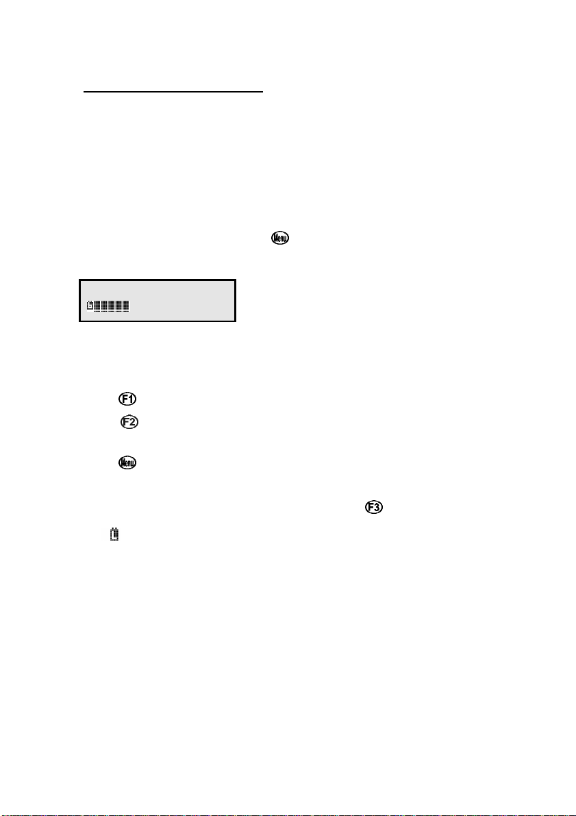
2. Select Battery Saver Set-up ( →→ F4:Setup →→ F1:Batt).
3. The battery saver menu is now displayed.
Batt Saver F1:OFF
100% >F2:ON
The arrow indicates the current selection.
The bar graph and percentage indicate the approximate level of
charge in the battery.
4. Press to disable the battery saver function for continuous use.
Press to enable the battery saver function. The meter will switch
itself off if no key has been pressed for five minutes.
Press to quit the battery saver menu and retain the current setting.
5. NOTE: For troubleshooting purposes, the battery volts can also be
displayed in the battery saver menu. Press to display battery volts.
The symbol flashes when the battery volts drops below 5.60 volts.
At 5.00 volts the meter turns itself off.
Page 35
Page 34
13. Clock Function
13.1 Setting the Clock
1. Select the Clock Set-up menu ( →→ F4:Setup →→ F2:Clock).
2. The display now shows the current date and time. The cursor starts at
the day. For example…
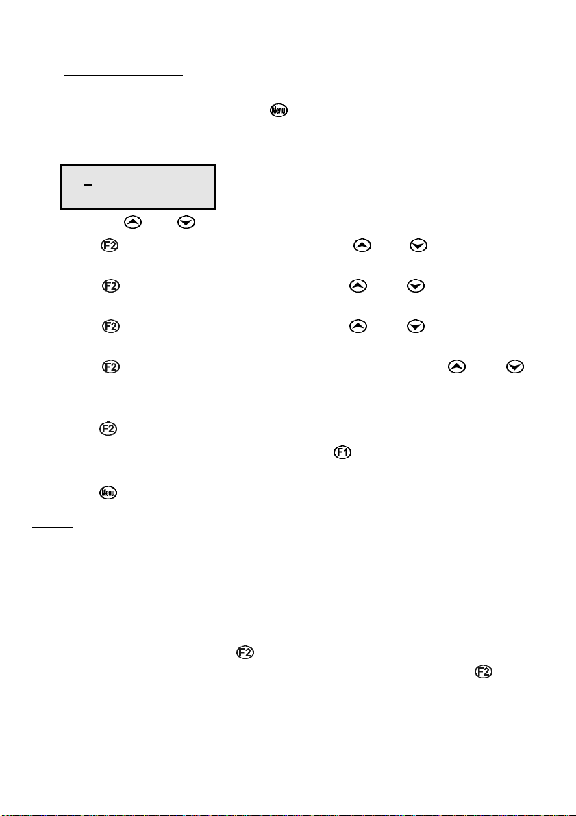
31/12/02 12:00
F1:< F2:> ↑↑↓↓:Set
Press the and keys until the day is correct.
3. Press to move to the month. Press the and keys until the
month is correct.
4. Press to move to the year. Press the and keys until the
year is correct.
5. Press to move to the hour. Press the and keys until the
hour is correct.
6. Press to move the cursor to the minutes. Press the and
keys until the minutes are correct.
7. Check that the date and time are correct.
Press to save the settings.
If any changes are needed, press the key to move left to the
desired position.
Press to quit without resetting the clock.
Notes
1. The WP-80 does not test for a valid day of the month when setting the
clock (eg: attempting to enter 31/02/96 is not corrected).
2. The WP-80 does test for leap years.
13.2 Displaying or Hiding the Clock
The date and time are normally displayed along with the pH or mV and
Temperature readings. Press in normal display mode to alternatively
display or hide the clock. When Relative mV is selected, the key
alternatively displays the clock or absolute mV.
Page 36
Page 35
14. Selecting Buffers for Auto Buffer Recognition
The WP-80 is factory set to automatically recognise pH4.00, pH6.88 and
pH9.23 buffers. However, some users may prefer to use pH7.00 instead
of pH6.88 and pH10.00 instead of pH9.23. The following procedure
describes how to set which of these buffers are automatically recognised
at calibration.
1. Switch the meter OFF with the key.
2. Press and HOLD the key while switching the meter back on.
3. The buffer selection menu is now displayed.
Select >F1:6.88pH
Buffer F2:7.00pH
The arrow indicates the current selection.
4. Press to select pH6.88 as the primary buffer.
Press to select pH7.00 as the primary buffer.
Press to quit buffer selection and retain the current setting.
5. The display will now show the currently selected high pH buffer.
Select >F1:9.23pH
Buffer F2:10.0pH
The arrow indicates the current selection.
6. Press to select pH9.23 as the high pH buffer.
Press to select pH10.00 as the high pH buffer (the display shows
10.0 for the latter, but this buffer is stored as pH10.00).
Press to quit buffer selection and retain the current setting.
7. The setting is kept in memory when the meter is switched off, even if
the battery is removed. The buffers are re-set to pH6.88 and pH9.23
during initialisation.
Note: pH6.88 buffer is a DIN 19266 and NBS Primary-standard pH
solution. Its use is highly recommended for the most accurate
possible results. If pH7.00 buffer is used, ensure that it is
manufactured to 0.01pH accuracy. pH7.00 buffer has a buffer
capacity less than half that of pH6.88 buffer and is therefore much
less stable.
Page 37

Page 36
15. Initialising the WP-80
If the calibration settings of the WP-80 exceed the allowable limits, the
unit may need to be initialised to factory default values. This action may
be required if the electrode is replaced.
To initialise the WP-80:
1. Switch the WP-80 off.
2. Press and hold the key while switching the WP-80 back on.
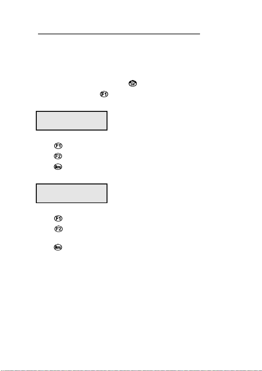
3. The following messages should be displayed:
Initialized
MUST ReCalibrate
then :
WP80s V3.5 S1234
pH mV Temp.
(The “s” after WP-80 is shown when the RS232 serial port option is
fitted)
4. The meter then displays pH and Temperature. Note that the decimal
points have been replaced with a ∗, to indicate that the unit requires
recalibration.
Note: When the WP-80 is initialised, the automatically recognised
buffers are re-set to pH4.00, pH6.88 and pH9.23. See section 14 if
you prefer to use pH7.00 instead of pH6.88 and pH10.00 instead
of pH9.23.
Page 38
Page 37
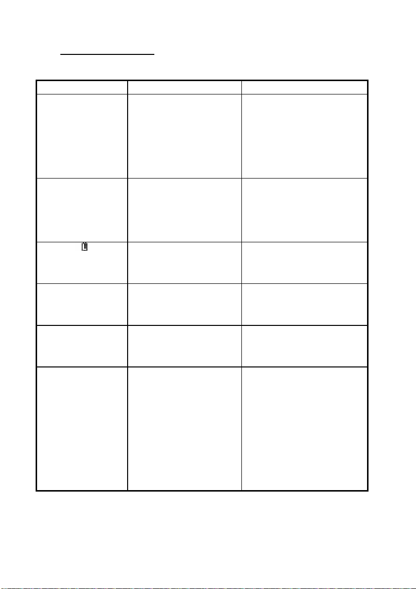
16. Troubleshooting
16.1 General Errors
Error Message Possible Causes Remedy
Factory Cal.
Failed
then:
See
Handbook
Memory Failed
Calibration Lost
then:
Initialized
MUST ReCalibrate
Flashing symbol.
Meter displays the
word OFF, and
switches off.
Meter will not turn
on.
Battery does not
charge up when
charger is connected.
The EEPROM chip which
contains the factory
calibration information has
failed.
User calibration settings
have been lost or corrupted.
Battery is below 5.60 volts. Recharge the battery. Note that
Battery is below 5.00 volts. Recharge the battery.
Battery is exhausted. Recharge the battery.
1. Faulty battery charger.
2. Faulty battery.
The unit must be returned to
TPS for service.
• mV & Temperature readings
may be up to 10% incorrect.
• pH readings will be accurate
after a 2-point calibration (use
manual temperature
compensation).
Re-calibrate the instrument. A
full 2-point calibration will be
required for pH (see section
4.1) and a 1 point calibration for
temperature (see section 7.1).
the unit will switch itself off
when the battery falls below
5.00 volts.
If this fails, check the charger.
If charger OK, replace the
battery.
If this fails, check the charger.
If charger OK, replace the
battery.
1. Connect the charger and
switch the power on.
2. Display the battery volts in
the battery saver menu (see
section 12).
3. If the battery volts are
increasing then the charger
is OK. If the battery volts
do not increase, then the
charger is faulty.
4. Replace the charger or the
battery, as required.
Page 39

Page 38
16.2 pH and mV Troubleshooting
Symptom Possible Causes Remedy
Unit fails to
calibrate, even with
new probe.
1 Point calibration
fails (Asymmetry is
greater than +/-1.00
pH).
2 Point calibration
fails (Slope is less
than 85.0%).
Unstable readings. 1. Electrolyte chamber needs
Calibration settings outside of
allowable limits due to previous
failed calibration.
1. Reference junction blocked.
2. Reference electrolyte
contaminated.
1. Incorrect primary buffer.
2. Glass bulb not clean.
3. Electrode is aged.
4. Connector is damp.
5. Buffers are inaccurate.
to be refilled.
2. Reference junction blocked.
3. Glass bulb not clean.
4. Bubble in glass bulb.
5. Faulty connection to meter.
6. Reference junction not
immersed.
7. KCl crystals around
reference junction, inside
the electrolyte chamber.
Initialize the unit. See section
15, Initialising the WP-80.
Clean reference junction, as per
instructions supplied with the
electrode.
Flush with distilled water and
replace electrolyte.
Ensure that you are using the
buffers which the WP-80 has
been set to automatically
recognise (see section 14).
Clean glass bulb as per
instructions supplied with the
electrode.
Attempt rejuvenation, as per
instructions supplied with the
electrode. If not successful,
replace electrode.
Dry in a warm place.
Replace buffers.
Refill with saturated KCl filling
solution.
Clean reference junction, as per
instructions supplied with the
electrode.
Clean glass bulb as per
instructions supplied with the
electrode.
Flick the electrode to remove
bubble.
Check connectors. Replace if
necessary.
Ensure that the bulb AND the
reference junction are fully
immersed.
Rinse electrolyte chamber with
warm distilled water until
dissolved. Replace electrolyte.
Continued next page...
Page 40

Page 39
pH and mV Troubleshooting, continued...
Inaccurate readings,
even when
calibration is
successful.
Displays 7.00 for all
solutions.
Displays 4-5 pH for
all solutions.
Reference junction blocked. Clean reference junction, as per
instructions supplied with the
electrode.
Electrical short in connector. 1. Check connector. Replace if
necessary.
2. Replace electrode.
Glass bulb or internal stem
cracked.
Replace electrode.
16.3 Temperature Troubleshooting
Symptom Possible Causes Remedy
Displays “Man”
when temperature
probe is plugged in.
Temperature
inaccurate and
cannot be
calibrated.
1. Faulty temperature probe. Fit new temperature probe, part
number 121247.
1. Faulty connector.
2. Faulty temperature probe.
Check the connector and
replace if necessary.
Fit new temperature probe, part
number 121247.
Page 41

Page 40
17. Warranty
TPS Pty. Ltd. guarantees all instruments and electrodes to be free from
defects in material and workmanship when subjected to normal use and
service. This guarantee is expressly limited to the servicing and/or
adjustment of an instrument returned to the Factory, or Authorised
Service Station, freight prepaid, within twelve (12) months from the date
of delivery, and to the repairing, replacing, or adjusting of parts which
upon inspection are found to be defective. Warranty period on
rechargeable batteries and electrodes is three (3) months.
There are no express or implied warranties which extend beyond the face
hereof, and TPS Pty. Ltd. is not liable for any incidental or consequential
damages arising from the use or misuse of this equipment, or from
interpretation of information derived from the equipment.
Shipping damage is not covered by this warranty.
PLEASE NOTE:
A guarantee card is packed with the instrument or electrode. This card
must be completed at the time of purchase and the registration section
returned to TPS Pty. Ltd. within 7 days. No claims will be recognised
without the original guarantee card or other proof of purchase. This
warranty becomes invalid if modifications or repairs are attempted by
unauthorised persons, or the serial number is missing.
PROCEDURE FOR SERVICE
If you feel that this equipment is in need of repair, please re-read the
manual. Sometimes, instruments are received for "repair" in perfect
working order. This can occur where batteries simply require replacement
or re-charging, or where the electrode simply requires cleaning or
replacement.
TPS Pty. Ltd. has a fine reputation for prompt and efficient service. In just
a few days, our factory service engineers and technicians will examine
and repair your equipment to your full satisfaction.
To obtain this service, please follow this procedure:
Return the instrument AND ALL SENSORS to TPS freight pre-paid and
insured in its original packing or suitable equivalent. INSIST on a proof of
delivery receipt from the carrier for your protection in the case of shipping
claims for transit loss or damage. It is your responsibility as the sender to
ensure that TPS receives the unit.
Page 42

Page 41
Please check that the following is enclosed with your equipment:
• Your Name and daytime phone number.
• Your company name, ORDER number, and return street address.
• A description of the fault. (Please be SPECIFIC.)
(Note: "Please Repair" does NOT describe a fault.)
Your equipment will be repaired and returned to you by air express where
possible.
For out-of-warranty units, a repair cost will be calculated from parts and
labour costs. If payment is not received for the additional charges within
30 days, or if you decline to have the equipment repaired, the complete
unit will be returned to you freight paid, not repaired. For full-account
customers, the repair charges will be debited to your account.
• Always describe the fault in writing.
• Always return the sensors with the meter.
Page 43
Page 42
mV
18. Appendices
18.1 pH Electrode Fundamentals
A combination pH Electrode is two electrodes in one. The sensing
membrane is the round or spear shaped bulb at the tip of the electrode.
This produces a voltage that changes with the pH of the Solution. This
voltage is measured with respect to the second part of the electrode, the
reference section. The reference section makes contact with the sample
solution using a salt bridge, which is referred to as the reference junction.
A saturated solution of KCl is used to make contact with the sample. It is
vital that the KCl solution has an adequate flow rate in order to obtain
stable, accurate pH measurements.
18.1.1 Asymmetry of a pH Electrode
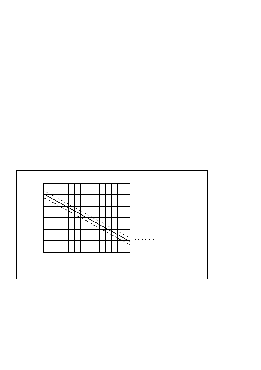
An “ideal” pH electrode produces 0 mV output at 7.00 pH. In practice, pH
electrodes, generally produce 0 mV output at slightly above or below 7.00
pH. The amount of variance from 7.00 pH is called the asymmetry. Figure
18-1 illustrates how asymmetry is expressed.
Response of pH Electrode, as a Function of Asymmetry
600
400
200
0
-200
-400
-600
0 7 14
pH
+1.00 pH Asymmetry
0.00 pH Asymmetry
-1.00 pH Asymmetry
Figure 18-1
Page 44
Page 43
mV
18.1.2 The Slope of a pH Electrode
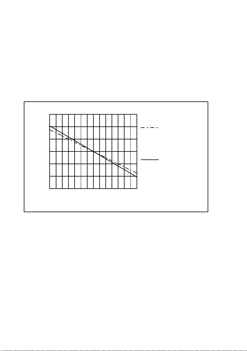
As mentioned above, a pH electrode produces 0 mV output at around
7.00 pH. As the pH goes up, an “ideal” pH electrode produces -59mV/pH
unit at 25 oC As the pH goes down, an ideal pH electrode produces
+59mV/pH unit. In practice, pH electrodes usually produce slightly less
than this. The output of a pH electrode is expressed as a percentage of
an ideal electrode. For example, an ideal electrode that produces
59mV/pH unit has “100% Slope”. An electrode that produces 50.15mV/pH
unit has “85% Slope” (see Figure 18-2).
Response of pH Electrode, as a Function of Slope
600
400
200
0
-200
-400
-600
0 7 14
pH
85% Slope at 25 oC
(50.15mV/pH)
100% Slope at 25 oC
(59mV/pH)
Figure 18-2
Page 45
Page 44
mV
18.1.3 Temperature Compensation
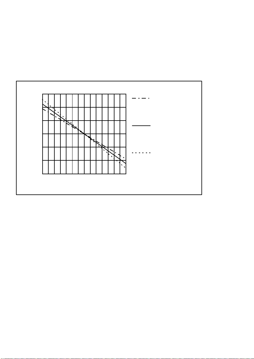
The slope of a pH electrode (section 18.1.2) is affected by temperature.
This effect is compensated for either by using an Automatic Temperature
Compensation (ATC) probe or by entering the sample temperature
manually. Figure 18-3 shows the slope of a pH electrode at various
temperatures.
pH Electrode Response, as a Function of Temperature
600
400
Electrode
Potential (mV) at
0 oC (54mV/pH)
200
0
-200
-400
-600
0 7 14
pH
Electrode
Potential (mV) at
50 oC (64mV/pH)
Electrode
Potential (mV) at
100 oC
(74mV/pH)
Figure 18-3
18.2 Checking the reference junction of a pH electrode.
If pH readings are inaccurate or unstable, the reference junction of the
electrode may be blocked. The following test can be performed to
determine if the reference junction of a pH electrode is making adequate
contact with the sample solution.
1. Calibrate the WP-80, as per section 4.1.
2. Dilute 1 part of pH6.88 buffer with 9 parts of distilled water.
3. Measure the pH of the diluted buffer. The result should be 7.06 +/-0.02
pH.
4. If the value obtained is outside of these limits, then clean the reference
junction, as per the instructions supplied with the pH electrode.
5. Re-calibrate the WP-80 and repeat the test.
6. If the value obtained is still outside 7.06 +/-0.02 pH, then the electrode
should be replaced.
Page 46

Page 45
18.3 Determining if an instrument or electrode is faulty
The following test can be performed to help determine if the WP-80 or the
pH electrode is faulty.
1. Initialize the WP-80 (see section 15).
2. Disconnect the pH electrode.
3. Connect the centre pin of the pH/mV connector with the outside frame
of the connector, using a short piece of wire or a paper clip etc.
4. The meter should read approximately 7.00. If you press the key,
the
WP-80 will calibrate to around 6.88 pH, depending upon the
temperature readout.
5. If the WP-80 is operating correctly, the reading should be totally stable
with the wire firmly in place. If not, the meter requires servicing.
6. Now carefully disconnect the wire from the centre pin only (make sure
the other end of the wire remains connected to the outside frame of the
connector).
7. The reading should steadily drift away from 7.00 (either up or down) at
a rate of approximately 1 pH or less every 3 seconds. If the drift rate is
faster than this, then input circuitry of the WP-80 is faulty and requires
servicing.
18.4 Instrument firmware version number.
If you need to phone or fax TPS for any further technical assistance, the
version number of your WP-80 firmware may of benefit to us. The version
number is displayed by the WP-80 at turn-on.
 Loading...