

TPM SmartPAC SPC-3201D, SmartPAC SPC-3204D, SmartPAC SPC-3221, SmartPAC SPC-3212 User Manual

TPM SPC-3000 User Manual
1
SmartPAC
SPC-3000 User Manual
Version: V2.1 2017Dec01
To properly use the product, read this manual thoroughly is necessary.
Part No.: 81-00SPC300-021

TPM SPC-3000 User Manual
2
Revision History
Date Revision Description Author
2016/3/30
1.0
Document creation.
Kelvin
2016/8/12 1.1 Revise GPIO signal circuit. Kelvin
2016/11/17 2.0 Document revision. Lyra
2017/12/01 2.1 Add SPE-L121D-2PA and SPE-C116D description Kelvin

TPM SPC-3000 User Manual
3
© Copyright 2012 TPM
The product, including the product itself, the accessories, the software, the manual and the software
description in it, without the permission of TPM Inc. (“TPM”), is not allowed to be reproduced, transmitted,
transcribed, stored in a retrieval system, or translated into any language in any form or by any means, except
the documentation kept by the purchaser for backup purposes.
The names of products and corporations appearing in this manual may or may not be registered trademarks,
and may or may not have copyrights of their respective companies. These names should be used only for
identification or explanation, and to the owners’ benefit, should not be infringed without any intention.
The product’s name and version number are both printed on the product itself. Released manual visions for
each product design are represented by the digit before and after the period of the manual vision number.
Manual updates are represented by the third digit in the manual vision number.
Trademark
MS-DOS and Windows 95/98/NT/2000/XP, Visual Studio, Visual C++, Visual BASIC are registered
trademarks of Microsoft.
BCB (Borland C++ Builder) is registered trademark of Borland.
Other product names mentioned herein are used for identification purposes only and may be trademarks
and/or registered trademarks of their respective companies.

TPM SPC-3000 User Manual
4
Electrical safely
To prevent electrical shock hazard, disconnect the power cable from the electrical outlet before
relocating the system.
When adding or removing devices to or from the system, ensure that the power cables for the devices
are unplugged before the signal cables are connected. Disconnect all power cables from the existing
system before you add a device.
Before connecting or removing signal cables from motherboard, ensure that all power cables are
unplugged.
Seek professional assistance before using an adapter or extension card. These devices could interrupt
the grounding circuit.
Make sure that your power supply is set to the voltage available in your area.
If the power supply is broken, contact a qualified service technician or your retailer.
Operational saf e l y
Please carefully read all the manuals that came with the package, before installing the new device.
Before use ensure all cables are correctly connected and the power cables are not damaged. If you
detect and damage, contact the dealer immediately.
To avoid short circuits, keep paper clips, screws, and staples away from connectors, slots, sockets and
circuitry.
Avoid dust, humidity, and temperature extremes. Do not place the product in any area where it may
become wet.
If you encounter technical problems with the product, contact a qualified service technician or the
dealer.

TPM SPC-3000 User Manual
5
Contents
CONTENTS .................................................................................................................................................................................. 5
1. SPC-3000 INTRODUCTION ....................................................................................................................................................... 8
1.1. INTRODUCTION ............................................................................................................................................................................ 8
1.1.1. Architecture ............................................................................................................................................................ 8
1.1.1. Mechanical Dimension .......................................................................................................................................... 9
1.2. FEATURES.................................................................................................................................................................................. 11
1.2.1. Fan-less Design .................................................................................................................................................... 11
1.2.2. Flexible Extension ............................................................................................................................................... 12
1.2.3. High Security ....................................................................................................................................................... 13
2. CPU BOARD .......................................................................................................................................................................... 14
2.1. BLOCK DIAGRAM ........................................................................................................................................................................ 14
2.2. BOARD LAYOU T .......................................................................................................................................................................... 15
2.3. EXTERNAL I/O CONNECTORS ........................................................................................................................................................ 16
2.4. COM 1/2 SERIAL PORT .............................................................................................................................................................. 17
2.5. USB3 PORT .............................................................................................................................................................................. 18
2.6. LAN PORT ................................................................................................................................................................................ 19
2.7. DVI-I PORT ............................................................................................................................................................................... 20
2.8. MEMORY .................................................................................................................................................................................. 22
2.9. SUMIT-ITA .............................................................................................................................................................................. 22
3. SPC-3201D WITH SPC-C114D ................................................................................................................................................ 23
3.1. SPECIFICATIONS .......................................................................................................................................................................... 23
3.2. INTRODUCTION .......................................................................................................................................................................... 24
3.3. SPE-C114D BOARD LAY OUT ........................................................................................................................................................ 25
3.4. POWER CONNECTOR ................................................................................................................................................................... 25
3.4.1. DC24V Input ........................................................................................................................................................ 26
3.4.2. ON/OFF Switch ................................................................................................................................................... 26
3.5. ISOLAT ED 8DI/8DO ................................................................................................................................................................... 27
3.6. EXTERNAL I/O CONNECTORS ........................................................................................................................................................ 29
3.6.1. LED Indicator ...................................................................................................................................................... 29
3.6.2. COM 3/4 and 5/6 Serial Port................................................................................................................................ 30
3.6.3. USB3 Port ............................................................................................................................................................ 31
3.6.4. miniPCIe .............................................................................................................................................................. 32
4. SPC-3204D WITH SPC-C116D ................................................................................................................................................ 33
4.1. SPECIFICATIONS .......................................................................................................................................................................... 33
4.2. INTRODUCTION .......................................................................................................................................................................... 34
4.3. SPE-C116D BOARD LAY OUT ........................................................................................................................................................ 35

TPM SPC-3000 User Manual
6
4.4. POWER CONNECTOR ................................................................................................................................................................... 35
4.4.1. DC24V Input ........................................................................................................................................................ 36
4.4.2. ON/OFF Switch ................................................................................................................................................... 36
4.5. ISOLAT ED 8DI/8DO ................................................................................................................................................................... 37
4.6. EXTERNAL I/O CONNECTORS ........................................................................................................................................................ 39
4.6.1. LED Indicator ...................................................................................................................................................... 40
4.6.2. COM 3/4 and 5/6 Serial Port................................................................................................................................ 41
4.6.1. COM 7/8 .............................................................................................................................................................. 42
4.6.2. USB2 Port ............................................................................................................................................................ 43
4.6.3. USB3 Port ............................................................................................................................................................ 44
5. SPC-3221 WITH SPC-L122D-CSM ........................................................................................................................................... 45
5.1. SPECIFICATIONS .......................................................................................................................................................................... 45
5.2. INTRODUCTION .......................................................................................................................................................................... 46
5.3. SPE-L122D-CSM BOARD LAYO UT................................................................................................................................................ 47
5.4. POWER CONNECTOR ................................................................................................................................................................... 47
5.4.1. DC24V Input ........................................................................................................................................................ 48
5.4.2. ON/OFF Switch ................................................................................................................................................... 48
5.5. CN1 ISOL AT ED 8DI/8DO ............................................................................................................................................................ 49
5.6. EXTERNAL I/O CONNECTORS ........................................................................................................................................................ 51
5.6.1. LED Indicator ...................................................................................................................................................... 52
5.6.2. USB3 Port ............................................................................................................................................................ 53
5.6.3. COM 3/4 and 5/6 Serial Port................................................................................................................................ 54
5.6.4. Mnet Motionnet Rings ......................................................................................................................................... 55
5.7. MOTIONNET .............................................................................................................................................................................. 56
6. SPC-3212 WITH SPC-L121D-2 PA ............................................................................................................................................ 57
6.1. SPECIFICATIONS .......................................................................................................................................................................... 57
6.2. INTRODUCTION .......................................................................................................................................................................... 58
6.3. SPE-L121D-2PA BOARD LAY OUT ................................................................................................................................................. 59
6.4. POWER CONNECTOR ................................................................................................................................................................... 59
6.4.1. DC24V Input ........................................................................................................................................................ 60
6.4.2. ON/OFF Switch ................................................................................................................................................... 60
6.5. ADVANCED DIGITAL I/O ............................................................................................................................................................... 61
6.6. EXTERNAL I/O CONNECTORS ........................................................................................................................................................ 64
6.6.1. LED Indicator ...................................................................................................................................................... 65
6.6.2. USB3 Port ............................................................................................................................................................ 66
6.6.3. USB2 Port ............................................................................................................................................................ 67
6.6.4. Mnet Motionnet Ring ........................................................................................................................................... 68
6.6.5. PoE Power Ethernet ............................................................................................................................................. 69
6.6.6. CN2 Analog Output ............................................................................................................................................. 70

TPM SPC-3000 User Manual
7
6.7. MOTIONNET .............................................................................................................................................................................. 71
7. APPENDIX A: TPM899 BIOS SETUP ........................................................................................................................................ 72
7.1. MAIN MENU ............................................................................................................................................................................. 72
7.2. SELECT SERIAL PORT 2 TRANSMISSION PROTOCOL ............................................................................................................................ 73
7.3. SIO POWER FAILURE ................................................................................................................................................................... 74
8. APPENDIX B: EEPROM .......................................................................................................................................................... 75
9. APPENDIX C: PIN DEFINITION OF SUMIT-ITA ......................................................................................................................... 76
10. APPENDIX D: INTERNAL USB DONGLE INSTALLATION .......................................................................................................... 77
11. APPENDIX E: CABLE FOR COM PORT ................................................................................................................................... 79
11.1. Y CABLE FOR COM 1/2 ............................................................................................................................................................ 79
11.2. Y-CABLE FOR COM 3/4 AND 5/6 (OPTION) ................................................................................................................................. 81
12. APPENDIX F: MOTIONNET UTILITY - MYLINK ....................................................................................................................... 83
12.1. LOGIN OF MYLINK .................................................................................................................................................................... 84
TPM SPC-3000 User Manual
8
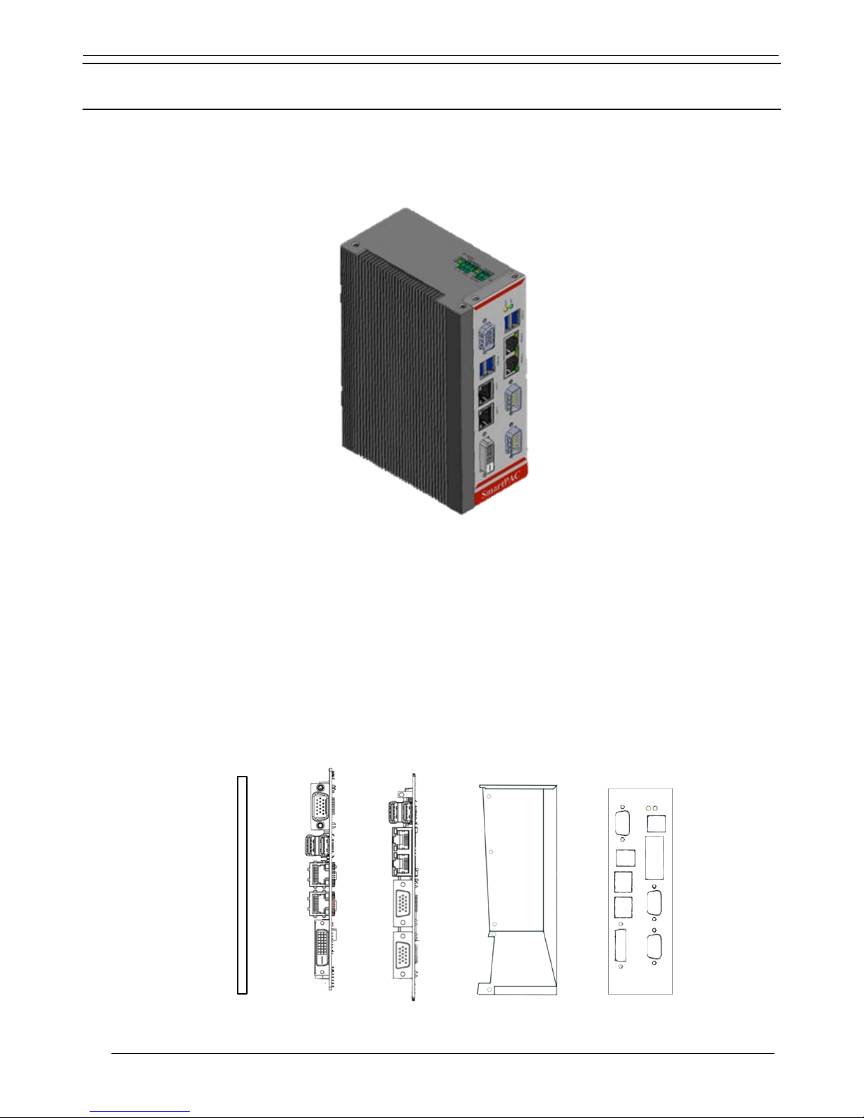
1. SPC-3000 Introduction
1.1. Introduction
Figure 1-1: SmartPAC SPC-3000
1.1.1. Architecture
The architecture of SPC-3000
= Heat sink + TPM899’s MB + SPE SUMIT add-on card + SSD-OS + Chassis + Front panel
TPM SPC-3000 User Manual
9
Figure 1-2: Heat Sink, MB, SPE, Chassis, Front Panel
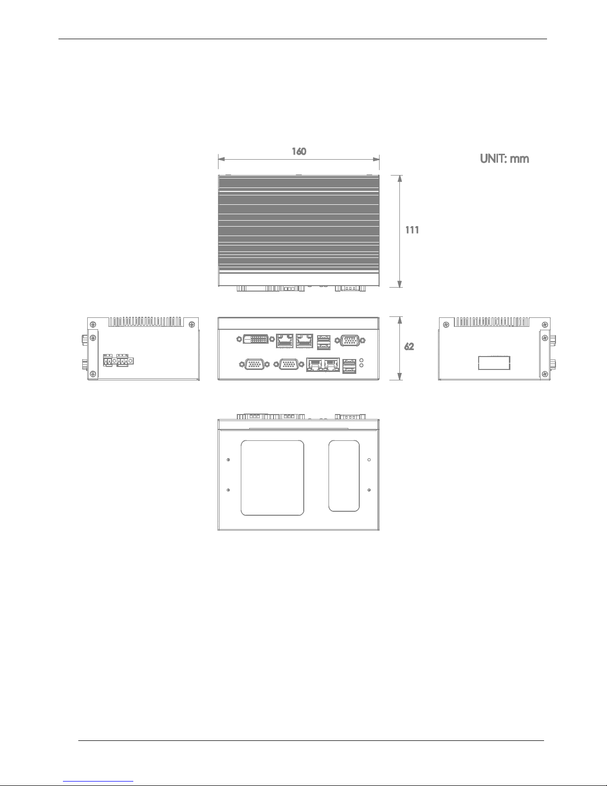
1.1.1. Mechanical Dimension
Figure 1-3: The dimensions of SmartPAC SPC-3000
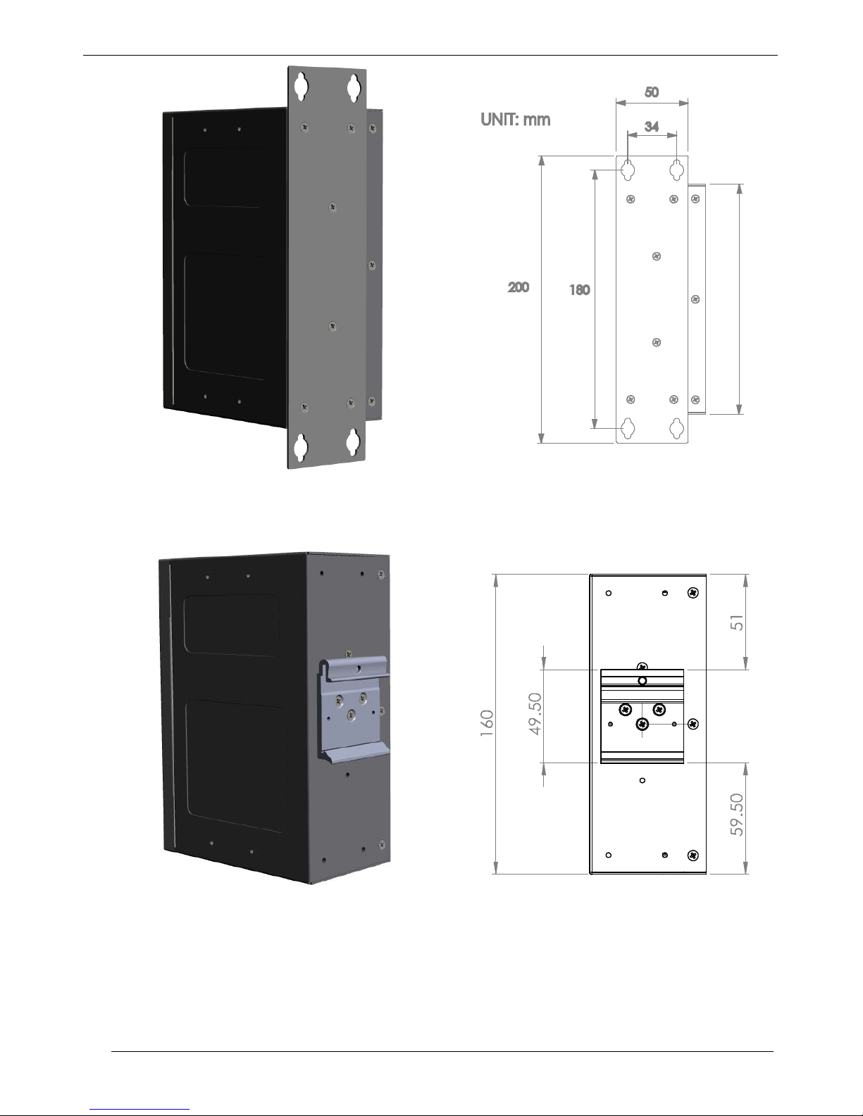
TPM SPC-3000 User Manual
10
Figure 1-4: The wal l mount drawing of SmartPAC SPC-3000
Figure 1-5: Th e DIN rail drawing of SmartPAC SPC-3000
TPM SPC-3000 User Manual
11
1.2. Features
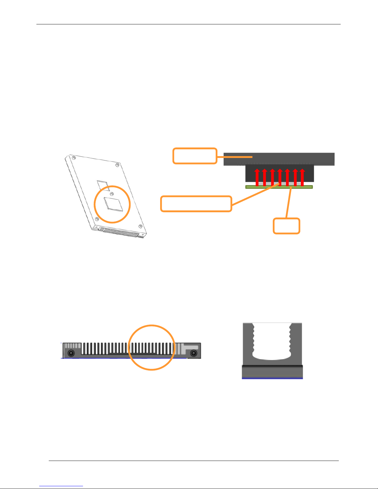
1.2.1. Fan-less Design
SPC-3000 Series are all fan-less design. Hence, the size of SPC-3000 is form factor. The dimension is
smaller than any other embedded system. It is suitable for different environment.
With fan-less design, the design of Heat Sink is important. The CPU and Heat Sink can directly contact
together with thermal grease to increase the efficiency of thermal conductivity.
Figure 1-6: Thermal conductivity
The surface area with curved shape increased about 50% will lead to high efficiency of dissipating.
Figure 1-7: Heat dissipation
Thermal grease
CPU
Heat sink
TPM SPC-3000 User Manual
12
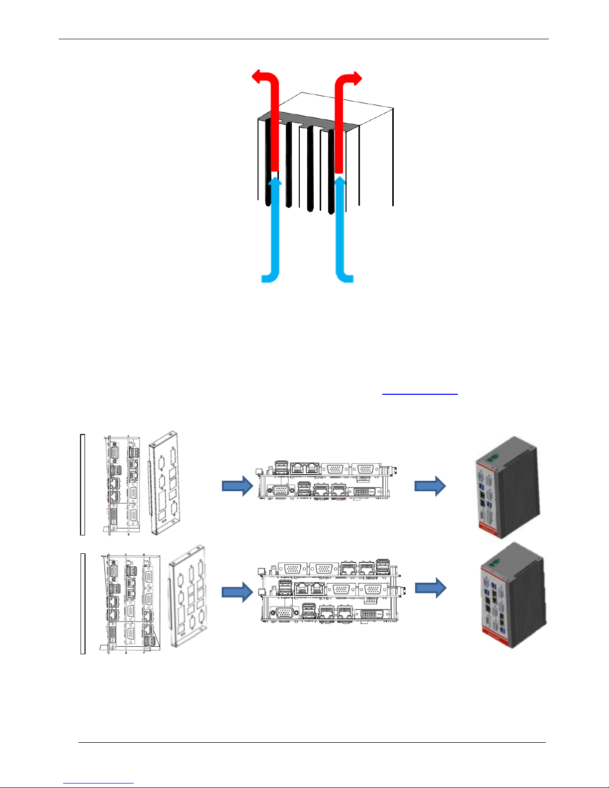
Vertical wall-mounted designed will result in better convection because heat can come out easily.
Figure 1-8: Convection
1.2.2. Flexible Extension
SPE add-on board is an extensible card. It can be customized for different function. SPE and MB can
connect together through the connector SUMIT-ITA. Please refer to “2.5 SUMIT-ITA” for detailed
information.
Figure 1-9: Flexible Extension
TPM SPC-3000 User Manual
13
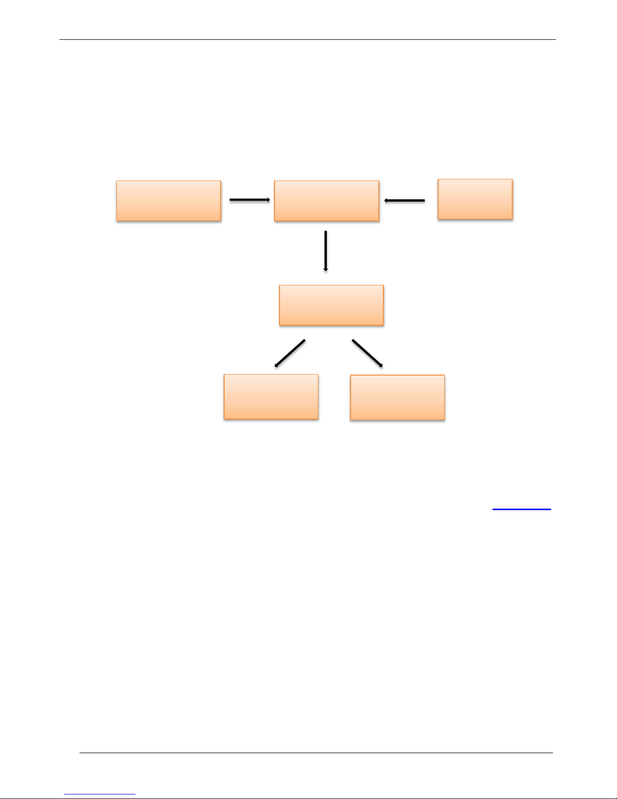
1.2.3. High Security
SPC-3000 has EEPROM on the CPU board and Secure IC on SUMIT Add-on card. Users can choose to
execute AES encryption on EEPROM or Secure IC. SI Key is provided by users. A registration key,
which can be stored into storage device and EEPROM, can be generated through AES encryption system.
When users load the program into SPC-3000 series, AES can prevent other people and TPM from
duplicating the program.
Figure 1-10: AES Encryption Syste m
SPC-3000 provides one inner USB socket for user to protect USB Dongle. Please refer to “Appendix D”
for the internal USB Dongle installation.
SI Key
AES Secure IC
Registration
Storage
Device
EEPROM
Users
TPM

TPM SPC-3000 User Manual
14
2. CPU Board
2.1. Block Diagram
Figure 2-1: Diagram of TPM899
System Hardware
CPU
Intel ® Pentium ® Processor N3710
1.6 GHz / 2.56 GHz (Boost), 4 Cores / 4 Threads 2MB L2 Cache
Memory Dual channel supports 2 DDR3L SO-DIMM, up to 8GB
Storage
SATA III for HDD/SSD
Graphics
Intel® HD Graphics 405
DVI-D : DVI-I + VGA
Audio
Internal stereo headphone, internal microphone
I/O Interface
Serial Ports
1 DB15 serial port:
1 RS-232, 1 RS-232/422/485 with automatic data flow control
LAN 2 Intel® GbE I211-AT
USB 3.0
Front : 2 USB3.0
SUMIT ITA : 2 USB3.0
Table 2-1: Specification of CPU Board
TPM SPC-3000 User Manual
15
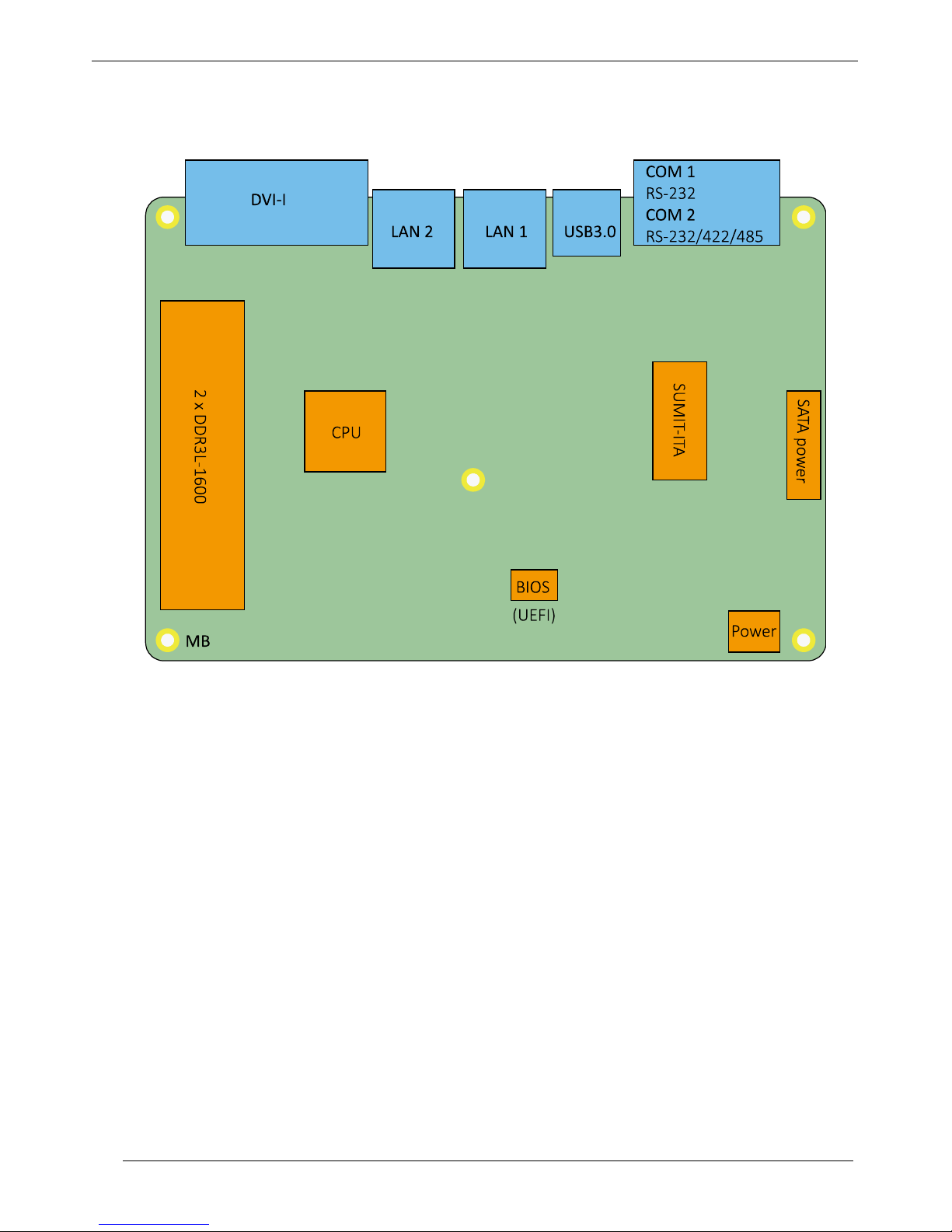
2.2. Board Layout
Figure 2-2: Layout of TPM899

TPM SPC-3000 User Manual
16
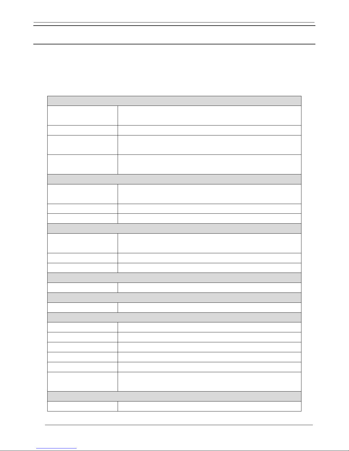
2.3. External I/O Connectors
Figure 2-3: Front I/O Interface of TPM899
Label Function Description
COM1/2
DB15 port supports 1 RS232 and 1 RS232/422/485 compatible serial devices.
USB Provides extensions for USB 2.0/1.1 devices.
LAN Used to connect the system to a local area network.
DVI-I Used to connect an analog VGA monitor and a digital DVI-D monitor.
Figure 2-4: Front side conne ctor of TPM899
COM1/2
USB3.0
LAN 1
LAN 2
DVI-I
TPM SPC-3000 User Manual
17
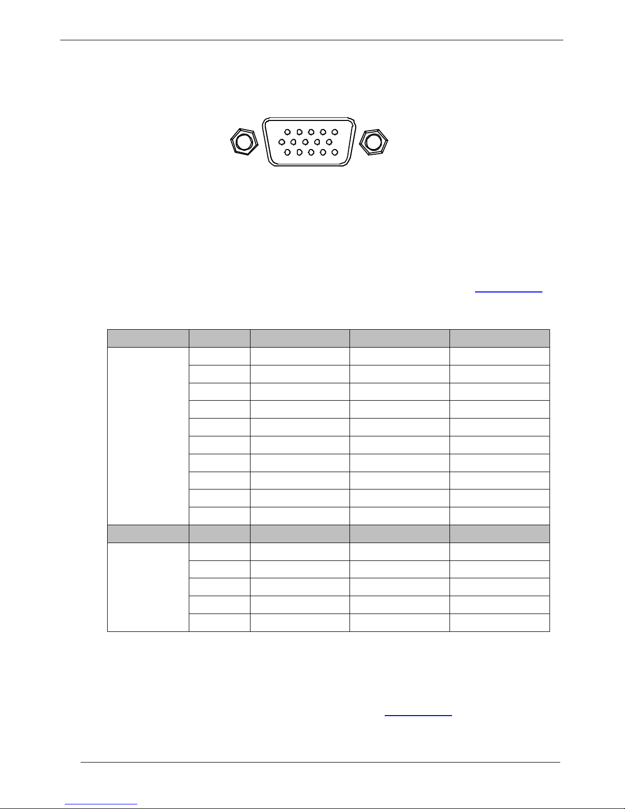
2.4. COM 1/2 Serial Port
Figure 2-5: Serial Port
Serial ports 1 and 2 have combined in a male DB15 connector and port 2 can be configured for R S-232,
RS-422, or RS-485 with auto flow control communication. Serial port 2 default setting is RS-232. It could
be adjusted as RS-422 or RS-485 by changing the settings in the BIOS. Please refer to “Appendix A.2” for
BIOS setting. The pin assignments of COM 1/2 are shown in the following table:
COM Port Pin NO. RS-232 RS-422 (4-Wire) RS-485 (2-Wire)
1
1
DCD
---
---
2 RXD --- --3 TXD --- --4 DTR --- --5 GND --- --6 DSR --- ---
7
RTS
---
---
8 CTS --- --9 RI --- ---
10 --- --- ---
COM Port
Pin NO.
RS-232
RS-422 (4-Wire)
RS-485 (2-Wire)
2
11 RXD RXD+ ---
12
TXD
RXD-
---
13 RTS TXD+ DATA+
14 CTS TXD- DATA15 GND GND GND
Figure 2-6: Pin Definition of COM 1/2 Serial Port
Users can use the Y-type cabl e to convert the 15-pin D-Sub connector into two 9-pin D-Sub connectors to
connect both COM1 and COM2 at the same time. Please refer to “Appendix E.1” for the Y -type cable of
COM 1/2.
1
5
11 15
TPM SPC-3000 User Manual
18
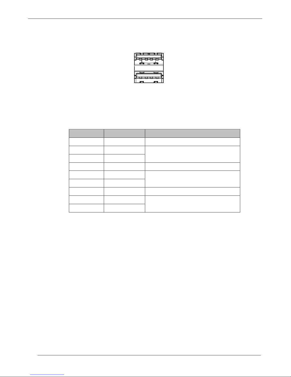
2.5. USB3 Port
Figure 2-7: USB3 Port
The USB port is 3.0. It is compatible with USB 2.0. The pin assignments are shown in the following
table:
Pin NO. Label Description
1
VBUS
Power
2 D-
USB 2.0 differential pair
3 D+
4 GND Ground
5 SSRX-
SuperSpeed transmitter differential pair
6 SSRX+
7
GND
Ground
8 SSTX-
SuperSpeed receiver differential pair
9 SSTX+
Figure 2-8: Pin Definition of USB 3 Port
TPM SPC-3000 User Manual
19
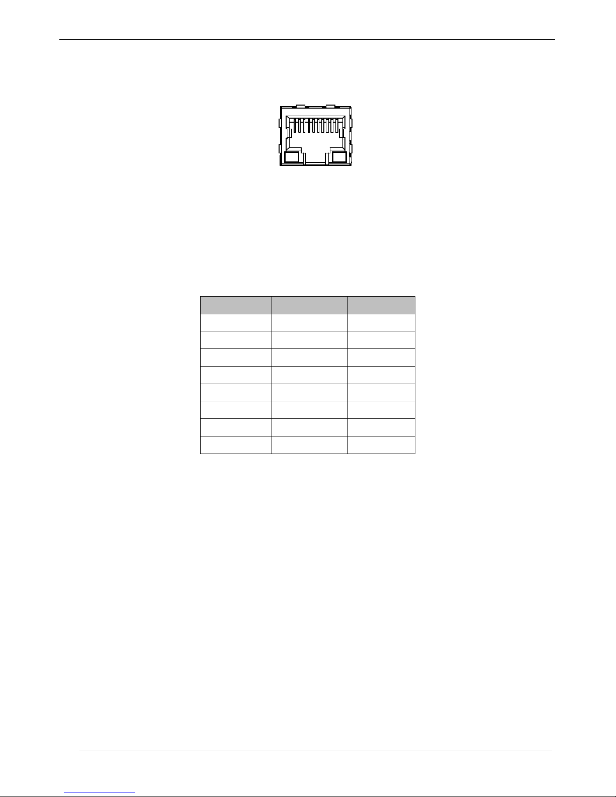
2.6. LAN Port
Figure 2-9: LAN Port
The LAN ports use standard RJ-45 jack connectors with LED indicators on the front side to show active/link
status and speed status. The LED indicators on the bottom corners show the cable is properly connected to
a 100 Mbps or 1000 Mbps Ethernet network. The pin assignments are shown in the following table:
Pin No. 10/100 Mbps 1000 Mbps
1
E_TX+
MDI0_P
2 E_TX- MDI0_N
3 E_RX+ MDI1_P
4 --- MDI2_P
5 --- MDI2_N
6 E_RX- MDI1_N
7
---
MDI3_P
8 --- MDI3_N
Figure 2-10: Pin Definition of LAN Port
8 1
TPM SPC-3000 User Manual
20
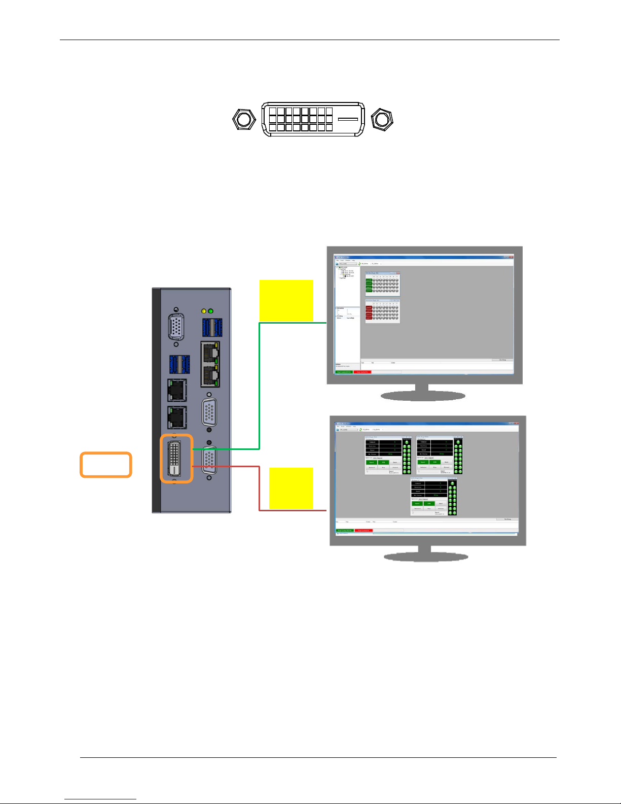
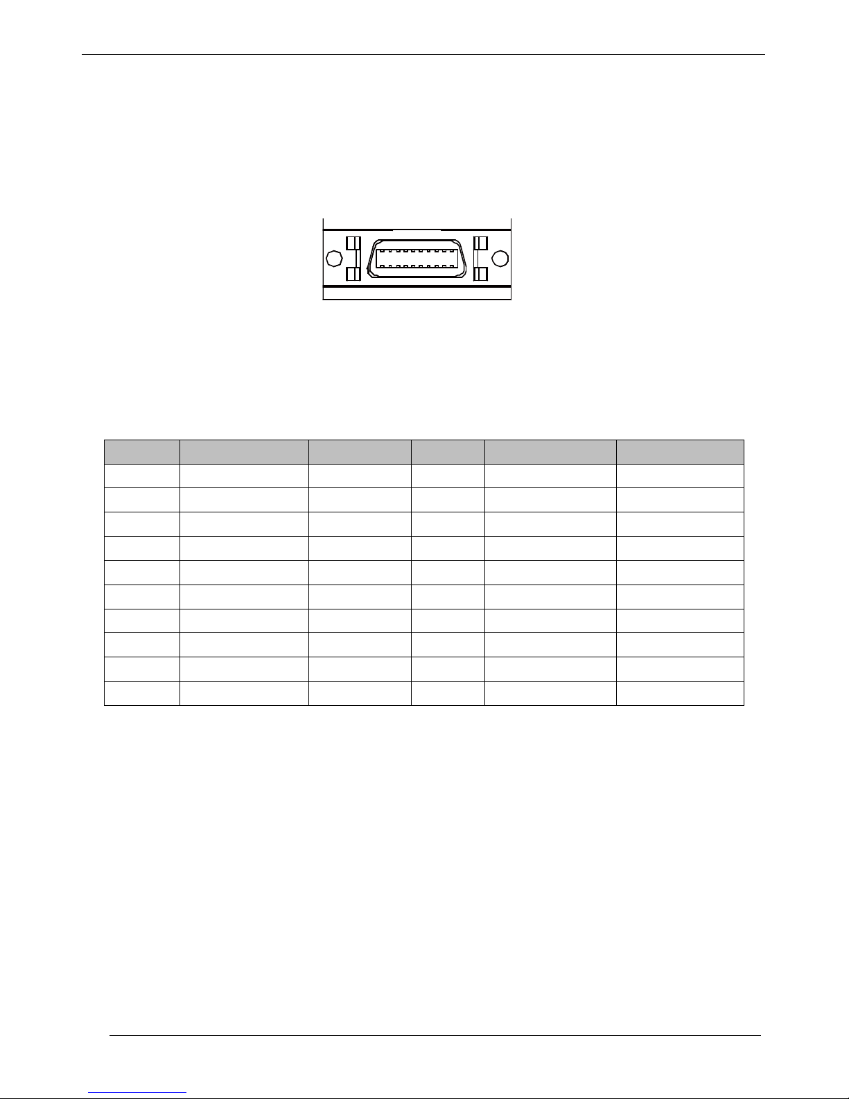
2.7. DVI-I Port
Figure 2-11: DVI-I Por t
The DVI-I port can both send out a digital signal and an analog signal. Users are allowed to use two
monitors simultaneously. Dual display is supported. The pin assignments are shown in the Figure 2-12.
Figure 2-12: Dual Display
DVI-I
DVI-D
VGA

TPM SPC-3000 User Manual
21
Pin NO. Label Pin NO. Label
1
TMDS Data 2-
15
GND
2 TMDS Data 2+ 16 Hot plug detect
3 TMDS Data 2/4 shield 17 TMDS Data 04 --- 18 TMDS Data 0+
5 --- 19 TMDS Data 0/5 shield
6 DDC clock 20 ---
7
DDC data
21
---
8 Analog vertical sync 22 TMDS clock shield
9 TMDS Data 1- 23 TMDS clock+
10 TMDS Data 1+ 24 TMDS clock11 TMDS Data 1/3 shield C1 Analog Red
12 --- C2 Analog Green
13
---
C3
Analog Blue
14 +5V C4 Analog Horizontal sync
Figure 2-13: Pin D e f inition of DVI-I Port
TPM SPC-3000 User Manual
22
2.8. Memory
Figure 2-14: DDR3L-1600 SO-DIMM
The system memory is Dual Channel DDR3L 1600 MHz SO-DIMM and it is up to 8GB.
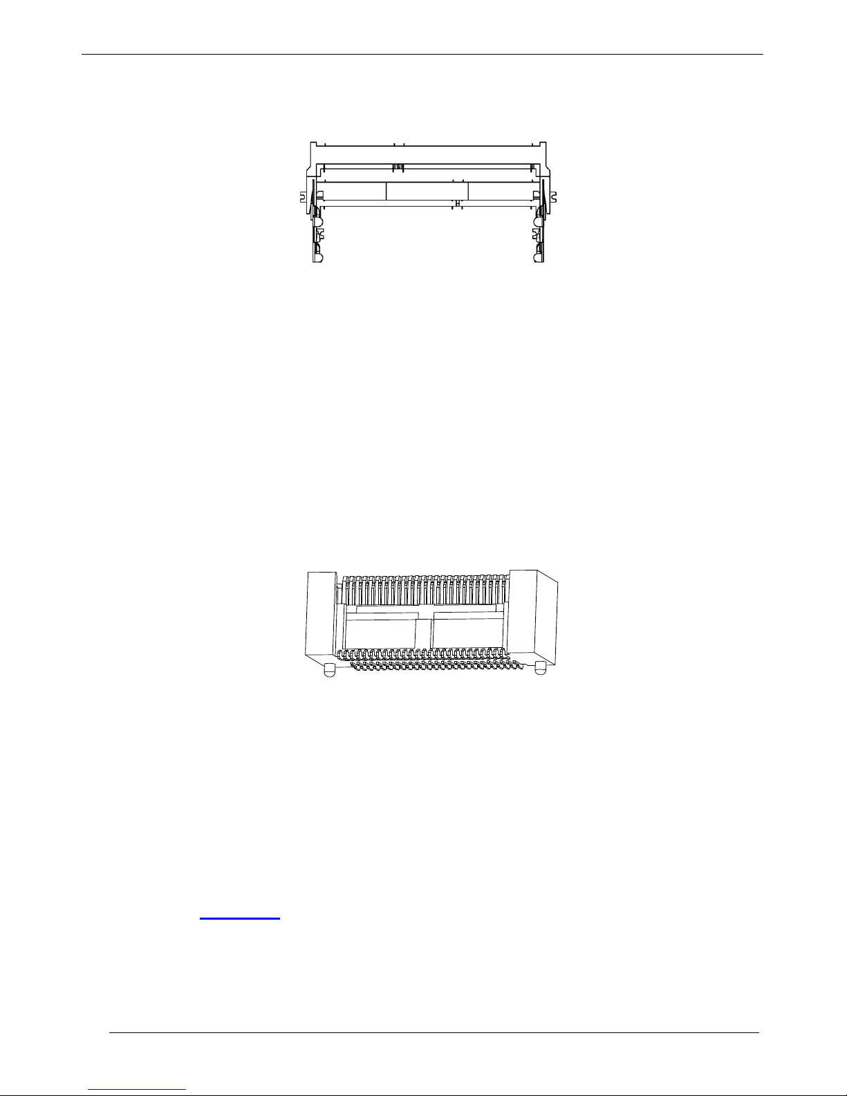
2.9. SUMIT-ITA
Figure 2-15: SUMIT-ITA
SUMIT-ITA is based on SUMIT A and it is a connector that connects with SPE and MB. It ’s designed by
iBASE and TPM with new specification. The capital “I”means “iBASE”, the capital “T”means “TPM”,
and the capital “A”means “SUMIT A”.
Please refer to “Appendix C” for the pin definition of SUMIT-ITA.
TPM SPC-3000 User Manual
23
3. SPC-3201D with SPC-C114D
3.1. Specifications
System Hardware
CPU
Intel ® Pentium ® Processor N3710
1.6 GHz / 2.56 GHz (Boost), 4 Cores / 4 Threads 2MB L2 Cache
Memory Dual channel supports 2 DDR3L SO-DIMM, up to 8GB
Storage
SATA III for HDD/SSD
mSATA for SSD
Graphics
Intel® HD Graphics 405
DVI-D : DVI-I + VGA
I/O Interface
Serial Ports
3 DB15 serial port:
5 RS-232, 1 RS-232/422/485 with automatic data flow control
LAN
2 Intel® GbE I211-AT
USB 4x USB 3.0 ports
Security
USB
1x internal USB port
supporting installation of a USB dongle for
security function.
SID
Hardware IC with unique id
EEPROM 256 bytes
PCI Express
Mini PCIe 1 Mini PCIe for expansion
Expansion I/O
Isolated DI/O 8 Digital input and 8 Digital output
General
Operating System Windows Embedded 7
Dimensions
160 mm x 62 mm x 115 mm
Weight 1.38 kg
Construction
Aluminum chassis with fan-less design
Mounting Wall-mounting for DIN-rail
Power Requirements
ATX Power mode: 2-pin remote power on/off switch
24V DC input, 60 W (typical)
Environment
Operating temperature
0°C~60°C ( 32°F~140°F) ambient temperature with air flow
TPM SPC-3000 User Manual
24
Storage temperature -20°C~80°C (-4°F~176°F)
Humidity
90% (non-condensing @60°C)
Shock Protection
IEC 68 2-27
SSD: 50G @ Wall-mount, half sine, 11ms
HDD: 20G @ Wall-mount, half sine, 11ms
Vibration Protection
IEC 68 2-64 (Random 1 Oct./min, 1hr/axis.)
SSD: 5 Grms @ 5~500Hz,
HDD: 1 Grms @ 5~500Hz
Figure 3-1: Specification of SPC-3201D
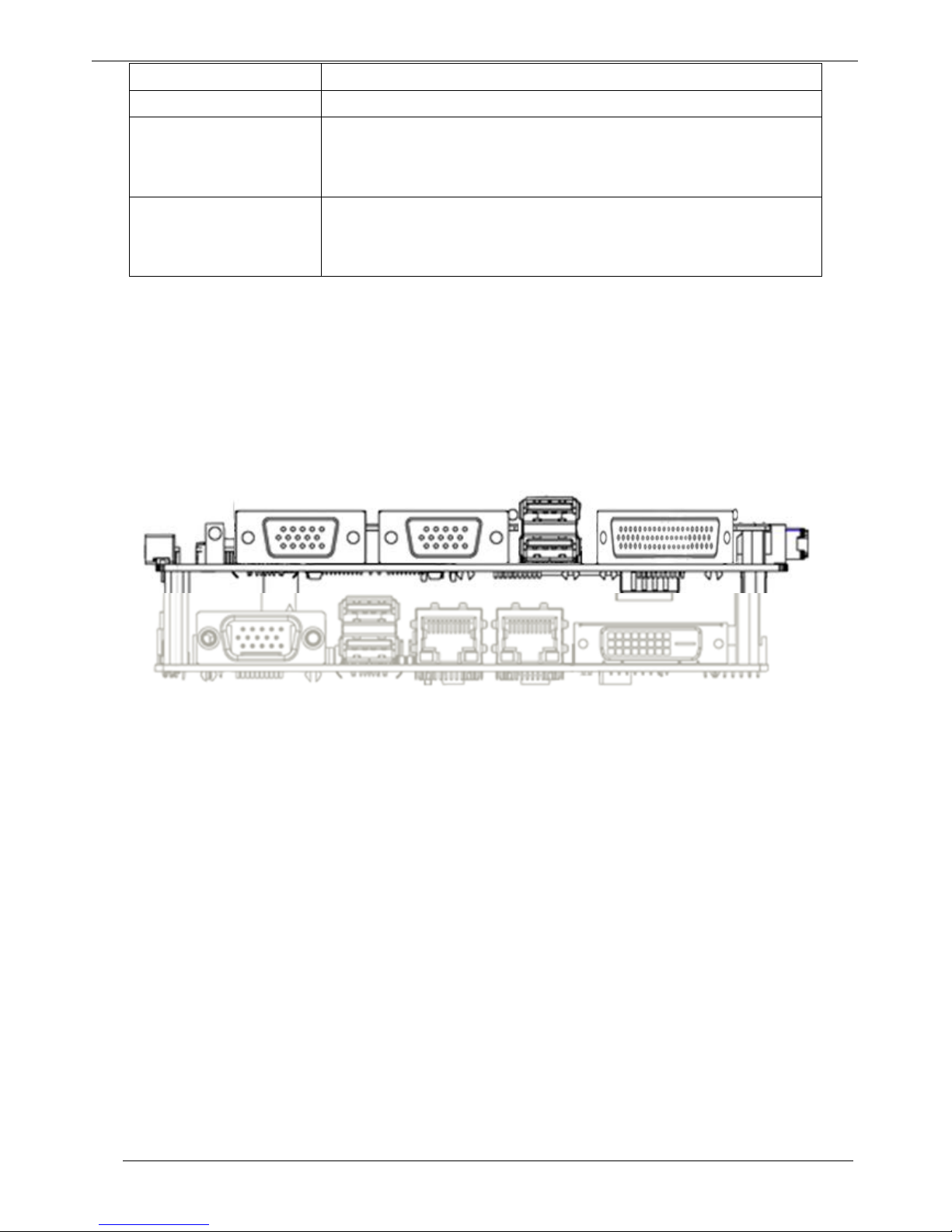
3.2. Introduction
The architecture of SPC-3201D = TPM899 CPU Board + SPE-C114D
Figure 3-2: Architecture of SPC-3201D
TPM SPC-3000 User Manual
25
3.3. SPE-C114D Board Layout
Figure 3-3: Layout of SPE-C114D
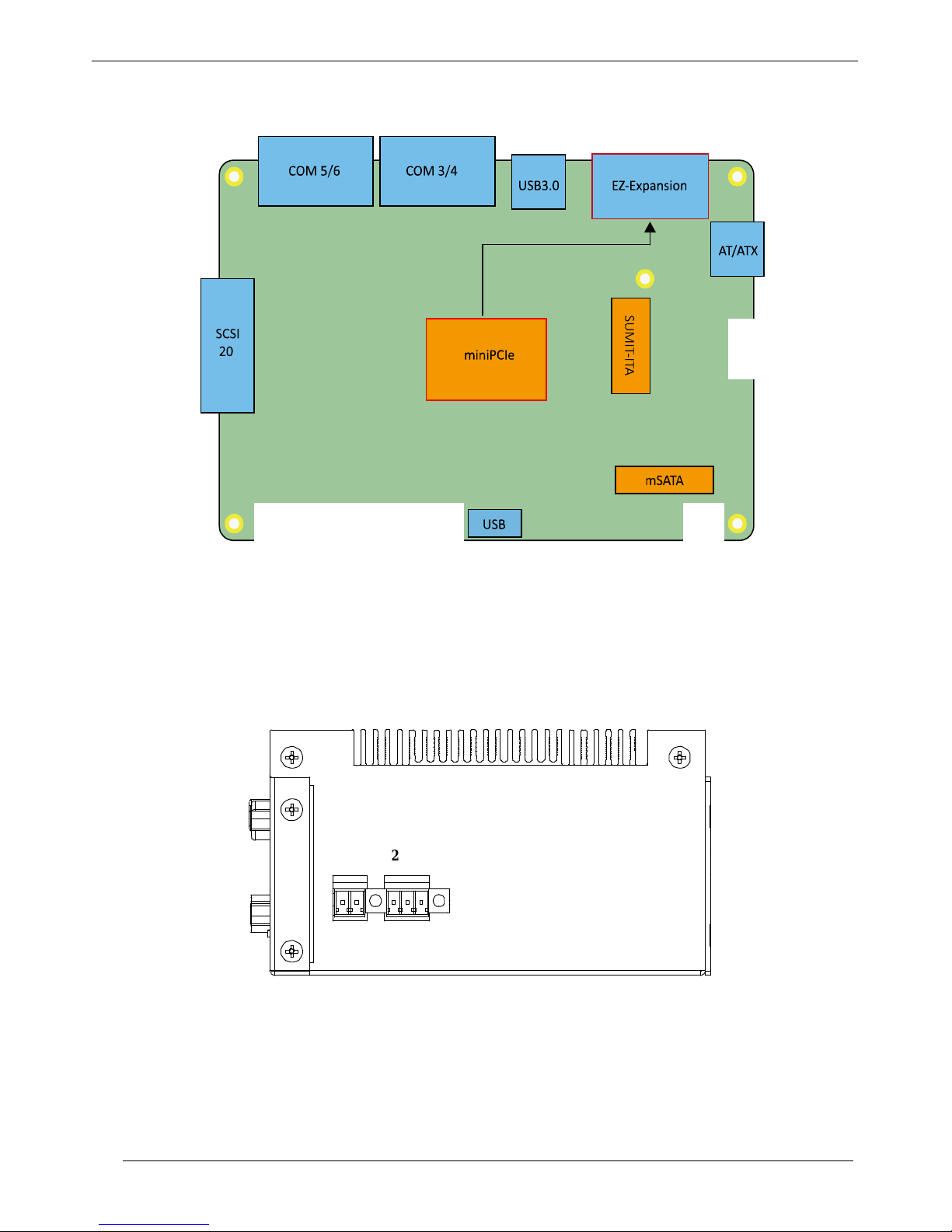
3.4. Power Connector
Figure 3-4: Top Side Connector
24VDC PWR-ON
GND V- V+
TPM SPC-3000 User Manual
26
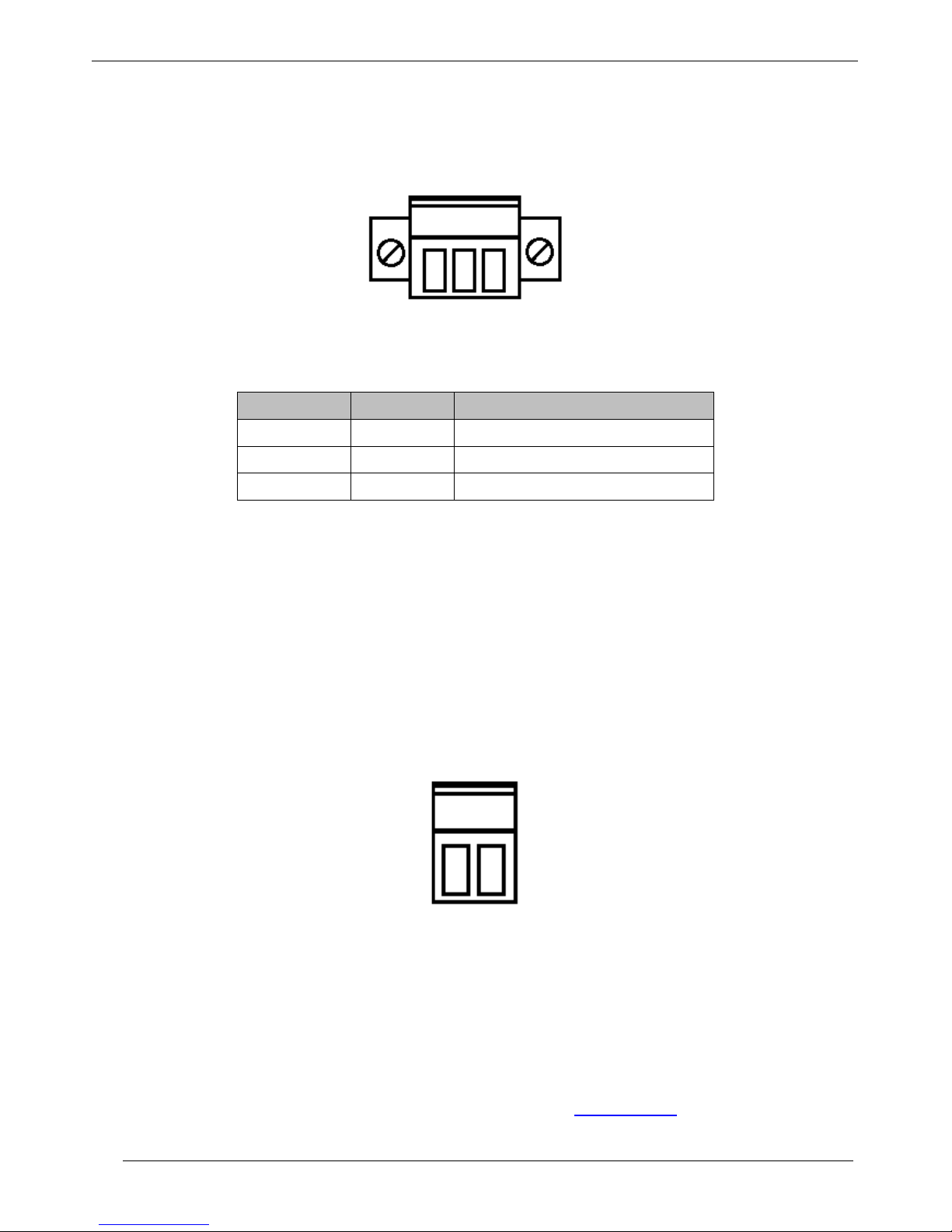
3.4.1. DC24V Input
Figure 3-5: 24V DC Input
Pin No. Label Description
1
24V
24V DC power input
2 GND Ground
3 FG Frame ground
Figure 3-6: Pin Definition of Power Connect or
3.4.2. ON/OFF Switch
Figure 3-7: Remote Power
It is a 2-pin power-on or power-off switch through Phoenix Contact terminal block. You could turn on or
off the system power by using this contact. This terminal block support dual function of soft power-on /
power-off (instant off or delay 4 second), and suspend mode.
There are two power mo des to choo se: AT/ATX. Pl ease refer to “Appendix A.3” for detailed information
1
TPM SPC-3000 User Manual
27
of power management in BIOS setting.
3.5. Isolated 8DI/8DO
Figure 3-8: Isolated DI/O
The SPC-3201D offers a 16-bit DIO (8-DI / 8-DO) SCSI-20 pin connector on the bottom side of I/O
interface. Each bit of DI and DO equipped with a photo-coupler for isolated protection. The pin assignments
are shown in the following table:
Pin No. Definition Description Pin No. Definition Description
1
EXT_IN0
GPIO Input 0
11
EXT_OUT0
GPIO Output 0
2 EXT_IN1 GPIO Input 1 12 EXT_OUT1 GPIO Output 1
3 EXT_IN2 GPIO Input 2 13 EXT_OUT2 GPIO Output 2
4 EXT_IN3 GPIO Input 3 14 EXT_OUT3 GPIO Output 3
5 EXT_IN4 GPIO Input 4 15 EXT_OUT4 GPIO Output 4
6 EXT_IN5 GPIO Input 5 16 EXT_OUT5 GPIO Output 5
7
EXT_IN6
GPIO Input 6
17
EXT_OUT6
GPIO Output 6
8 EXT_IN7 GPIO Input 7 18 EXT_OUT7 GPIO Output 7
9 DI_COM GPIO COM 19 Reserved NC
10 EGND GPIO GND 20 E24V External 24V DC
Figure 3-9: Pin Definition of the 8DI/DO
Digital GPIO output signal circuit in SINK mode (NPN) is illustrated as follows.
 Loading...