

Page 1
Rev: 1.0.0
1910011
TL-WR810N
300Mbps Wireless N Mini Router
531
Page 2

COPYRIGHT & TRADEMARKS
Specifications are subject to change without notice. is a registered trademark
of TP-LINK TECHNOLOGIES CO., LTD. Other brands and product names are trademarks or
registered trademar ks o f their r espective holders.
No part of the specifi cations may be repro duced i n any form or by any means or used to make any
derivative such as translation, transformation, or adaptation without permission from TP-LINK
TECHNOLOGIES CO., LTD. Copyright © 2016 TP-LINK TECHNOLOGIES CO., LTD. All rights
reserved.
http://www.tp-link.com
Page 3

FCC STATEMENT
This equipment has been tested and found to comply with the limits for a Class B digital device,
pursuant to part 15 of the FCC Rules. These limits are designed to provide reasonable protection
against harmful interference in a residential installation. This equipment generates, uses and can
radiate radio frequency energy and, if not installed and used in accordance with the instructions,
may cause harmful interference to radio communications. However, there is no guarantee that
interference will not occur in a particular installation. If this equipment does cause harmful
interference to radio or television r eception, w hich can be determin ed by turning t he equipment of f
and on, the user is encouraged to try to correct the interference by one or more of the following
measures:
• Reorient or relocate the receiving antenna.
• Increase the separat io n between the equipment and receiver.
• Connect the equipment into an outlet on a circuit different from that to which the receiver is
connected.
• Consult the dealer or an experienced radio/ TV technician for help.
This device complies with part 15 of the FCC Rules. Operation is subject to the following two
conditions:
1) This device may not cause harmful interference.
2) This device must accept any interference received, including interference that may cause
undesired operation.
Any changes or modifications not expressly approved by the party responsible for compliance
could void the user’s authority t o oper ate the equipment.
Note: The manufacturer is not responsible for any radio or TV interference caused by
unauthorized modifications to this equipment. Such modifications could void the user’s authority
to operate the equipment.
FCC RF Radiation Exposure Statement:
This equipment complies with FCC RF radiation exposure limits set forth for an uncontrolled
environment. This device and its antenna must not be co-located or operating in conjunction with
any other antenna or transmit t er.
“To comply with FCC RF exposure compliance requirements, this grant is applicable to only
Mobile Configurations. The antennas used for this transmitter must be installed to provide a
Page 4

only for purposes of gathering telemetry information for
d monitoring and resources accounting systems.
Permitted to use SRD for other purposes for outdoor
DSSS and other than FHSS wideband
separation distance of at least 20 cm from all persons and must not be co-located or operating in
conjunction with any other ant enna or t r ansmitter.”
CE Mark Warning
This is a Class B product. In a domestic environment, this product may cause radio interference,
in which case the user may be r equired t o take adequate measures.
RF Exposure Infor m ation
This device meets the EU requirements (1999/519/EC) on the limitation of exposure of the
general public to electro magnetic fields by way of health protection.
The device complies with RF s pecifications when the device used at 20 cm from your body.
National Restrictions
This device is intended for home and office use in all EU countries (and other countries following
the EU directive 1999/5/EC) without any limitation except f or the countries mentioned below:
Country Restriction Reason/remark
Belarus Not implemented
Norway Implemented This subsection does not a ppl y for the ge ographic al ar ea withi n
a radius of 20 km from the centre of Ny-Ålesund on Svalbard.
Italy Implemented The public use is subject to general authorisation by the
respective service provider.
Russian
Federation
Limited
implementation
1. SRD with FHSS modulation
1.1. Maximum 2.5 mW e.i.r.p.
1.2. Maximum 100 mW e.i.r.p. Permitted for use SRD for
outdoor applications without restriction on installation height
automate
applications only when the installation height is not exceeding
10 m above the ground surface.
1.3.Maximum 100 mW e.i.r.p. Indoor applications.
2. SRD with
modulation
2.1. Maximum mean e.i.r.p. density is 2 mW/MHz. Maximum
100 mW e.i.r.p.
2.2. Maximum m ean e.i.r.p. density is 20 mW /MHz. Maximum
Page 5

100 mW e.i.r.p. It is permitted to use SRD for outdoor
poses of gathering telemetry
applications only for pur
information for automated monitoring and resources accounting
systems or security systems.
2.3. Maximum m ean e.i.r.p. density is 10 mW /MHz. Maximum
100 mW e.i.r.p. Indoor applications.
Ukraine Limited
implementation
ATTENTION: Due to EU law, the country settings must be identical to the country where the
device is operating (impor tant due to non-harmonised frequencies in the EU).
e.i.r.p. ≤100 mW with built-in antenna with amplification fac tor
up to 6 dBi.
Canadian Compliance Statement
This device complies with Industry Canada license-exempt RSSs. Operation is subject to the
following two conditions:
1) This device may not c ause interference, and
2) This device must accept any interference, including interference that may cause undesired
operation of the device.
Le présent appareil est conforme aux CNR d’Industrie Canada applicables aux appareils radio
exempts de licence. L’exploitation est autorisée aux deux cond it io ns s uivantes :
1) l’appareil ne d oit pas produire de brouillage;
2) l’utilisateur de l’appareil doit accepter tout brouillage radioélectrique subi, meme si le
brouillage est susceptible d’en compromettre le fonctionne ment.
Radiation Exposur e Statement:
This equipment complies with IC radiation exposure limits set forth for an uncontrolled environment. This
equipment should be installed and operated with minimum distance 20cm between the radiator & your body.
Déclaration d'exposition aux radiations:
Cet équipement est conforme aux limites d'exposition aux rayonnements IC établies pour un environnement non
contrôlé. Cet équipement doit être installé et utilisé avec un minimum de 20 cm de distance entre la source de
rayonnement et votre corps.
Industry Canada Statement
CAN ICES-3 (B)/NMB-3(B)
Page 6

с правилами системи УкрСЕПРО на відповідність вимогам
Korea Warning Statements
당해 무선설비는 운용중 전파혼신 가능성이 있음.
NCC Notice
注意!
依據 低功率電波輻射性電機管理辦法
第十二條 經型式認證合格之低功率射頻電機,非經許可,公司、商號或使用者均不得擅自變更頻
加大功率或變更原設計之特性或功能。
率、
第十四條 低功率射頻電機之使用不得影響飛航安全及干擾合法通行;經發現有干擾現象
時,應立即停用,並改善至無干擾時方得繼續使用。前項合法通信,指依電信規定作業之無線電信。
低功率射頻電機需忍受合法通信或工業、科學以及醫療用電波輻射性電機設備之干擾。
減少電磁波影響,請妥適使用。
BSMI Notice
安全諮詢及注意事項
請使用原裝電源供應器或只能按照本產品注明的電源類型使用本產品。
清潔本產品之前請先拔掉電源線。請勿使用液體、噴霧清潔劑或濕布進行清潔。
注意防潮,請勿將水或其他液體潑灑到本產品上。
插槽與開口供通風使用,以確保本產品的操作可靠並防止過熱,請勿堵塞或覆蓋開口。
請勿將本產品置放於靠近熱源的地方。除非有正常的通風,否則不可放在密閉位置中。
請不要私自打開機殼,不要嘗試自行維修本產品,請由授權的專業人士進行此項工作。
Продукт сертифіковано згідно
нормативних документів та вимогам, що передбачені чинними законодавчими актами
України.
Page 7

equipment (WEEE). This means that this product must be handled pursuant to
European directive 2012/19/EU in order to be recycled or dismantled to minimize
Safety Information
When product has power button, the power button is one of the way to shut off the product;
when there is no power button, the only way to completely shut of f power is to discon nect t he
product or the power adapt er from the power source.
Don’t disassemble the product, or make repairs yourself. You run the risk of electric shock
and voiding the limited war r anty. I f you need service, please contact us.
Avoid water and wet locations.
Explanation of the symbols on the product label
Symbol Explanation
DC voltage
RECYCLING
This product bears the selective sorting symbol for Waste electrical and electronic
its impact on the environment.
User has the choice to give his product to a competent recycling organization or to
the retailer when he buys a new electrical or electronic equipment.
Page 8

TP-LINK TECHNOLOGIES CO., LTD
DECLARATION OF CONFORMITY
For the following equipme nt:
Product Description: 300Mbps Wireless N Mini Router
Model No.: TL-WR810N
Trademark: TP-LINK
We declare under our own responsibility that the above products satisfy all the technical
regulations applicable to the product within the scope of Counci l Dir ectives:
Directives 1999/5/EC, Directives 2011/65/EU
The above product is in conformity with the following standards or other normative documents
EN300328 V1.8.1
EN301489-1 V1.9.2 & EN 301489-17 V2.2.1
EN55022:2010+AC:2011
EN55024:2010
EN61000-3-2:2014
EN61000-3-3:2013
EN60950-1:2006+A11:2009+A1:2010+A12:2011+A2:2013
EN50385:2002
The product carries the CE Mark:
Person responsible for making this declaration:
Y a ng Hongliang
Product Manager of International Business
Date of issue: 2016.01.01
TP-LINK TECHNOLOGIES CO., LTD.
Building 24 (floors 1, 3, 4, 5), and 28 (floors 1-4) Central Science and Technology Park,
Shennan Rd, Nanshan, Shenzhen, China
Page 9

CONTENTS
Package Contents.................................................................................................................................. 1
Chapter 1. Introduction ....................................................................................................................... 2
1.1 Overview of the Router ....................................................................................................... 2
1.2 Conventions ........................................................................................................................ 3
1.3 Main Features ..................................................................................................................... 3
1.4 Pan el Layout ....................................................................................................................... 3
Chapter 2. Connecting the Router ..................................................................................................... 5
2.1 System Requirements ......................................................................................................... 5
2.2 Installation Environment Requirements .............................................................................. 5
2.3 Connecting the Router ........................................................................................................ 5
2.3.1 Standard Wireless Router Mode ............................................................................. 5
2.3.2 Access Point Mode ................................................................................................. 6
2.3.3 Repeater Mode ....................................................................................................... 7
2.3.4 Client Mode............................................................................................................. 7
2.3.5 Hotspot Router Mode ............................................................................................. 8
Chapter 3. Quick Installation Guide ................................................................................................... 9
3.1 TCP/IP Configuration .......................................................................................................... 9
3.2 Quick Installation Guide ....................................................................................................12
3.2.1 Standard Wireless Router Mode ...........................................................................13
3.2.2 Access Point Mode ...............................................................................................18
3.2.3 Repeater Mode .....................................................................................................19
3.2.4 Client Mode...........................................................................................................22
3.2.5 Hotspot Router Mode ...........................................................................................24
Chapter 4. Configuration for Standard Wireless Router Mode .....................................................29
4.1 Login .................................................................................................................................29
4.2 Status ................................................................................................................................29
4.3 Quick Setup .......................................................................................................................31
4.4 WPS ..................................................................................................................................31
4.5 Working Mode ...................................................................................................................35
4.6 Network .............................................................................................................................36
4.6.1 WAN ......................................................................................................................36
4.6.2 MAC Clone ...........................................................................................................45
- I -
Page 10

4.6.3 LAN .......................................................................................................................46
4.7 Wireless ............................................................................................................................47
4.7.1 Wireless Settings ..................................................................................................47
4.7.2 Wireless Security ..................................................................................................48
4.7.3 Wireless MAC Filtering .........................................................................................51
4.7.4 Wireless Advanced ...............................................................................................53
4.7.5 Wireless Statistics .................................................................................................54
4.8 DHCP ................................................................................................................................55
4.8.1 DHCP Settings ......................................................................................................55
4.8.2 DHCP Client List ...................................................................................................56
4.8.3 Address Reservation ............................................................................................57
4.9 USB Settings .....................................................................................................................58
4.9.1 Storage Sharing ....................................................................................................58
4.9.2 FTP Server ...........................................................................................................60
4.9.3 Media Server ........................................................................................................61
4.9.4 User Accounts .......................................................................................................63
4.10 Forwarding ........................................................................................................................64
4.10.1 Virtual Servers ......................................................................................................64
4.10.2 Port Triggering ......................................................................................................66
4.10.3 DMZ ......................................................................................................................68
4.10.4 UPnP ....................................................................................................................68
4.11 Security .............................................................................................................................69
4.11.1 Basic Security .......................................................................................................69
4.11.2 Advanced Security ................................................................................................71
4.11.3 Local Management ...............................................................................................72
4.11.4 Remote Management ...........................................................................................73
4.12 Parental Control ................................................................................................................74
4.13 Access Control ..................................................................................................................76
4.13.1 Rule ......................................................................................................................77
4.13.2 Host ......................................................................................................................79
4.13.3 Target ....................................................................................................................81
- II -
Page 11

4.13.4 Schedule ...............................................................................................................82
4.14 Advanced Routing .............................................................................................................84
4.14.1 Static Routing List .................................................................................................84
4.14.2 System Routing Table ...........................................................................................85
4.15 Bandwidth Control .............................................................................................................86
4.15.1 Control Settings ....................................................................................................86
4.15.2 Rule List ................................................................................................................87
4.16 IP & MAC Binding .............................................................................................................88
4.16.1 Binding Setting .....................................................................................................88
4.16.2 ARP List ................................................................................................................90
4.17 Dynamic DNS ....................................................................................................................90
4.17.1 No-IP DDNS .........................................................................................................91
4.17.2 Comexe DDNS .....................................................................................................91
4.17.3 Dyndns DDNS ......................................................................................................92
4.18 System T ools .....................................................................................................................93
4.18.1 Time Settings ........................................................................................................93
4.18.2 Diagnostic .............................................................................................................94
4.18.3 Firmware Upgrade ................................................................................................96
4.18.4 Factory Defaults....................................................................................................97
4.18.5 Backup & Restore .................................................................................................97
4.18.6 Reboot ..................................................................................................................98
4.18.7 Password ..............................................................................................................98
4.18.8 System Log ...........................................................................................................99
4.18.9 Statistics ..............................................................................................................100
Chapter 5. Configuration for Access Point Mode ........................................................................101
5.1 Login ...............................................................................................................................101
5.2 Status ..............................................................................................................................101
5.3 Quick Setup .....................................................................................................................103
5.4 WPS ................................................................................................................................103
5.5 Working Mode .................................................................................................................107
5.6 Network ...........................................................................................................................108
5.6.1 LAN .....................................................................................................................108
- III -
Page 12

5.7 Wireless ..........................................................................................................................109
5.7.1 Wireless Settings ................................................................................................109
5.7.2 Wireless Security ................................................................................................ 111
5.7.3 Wireless MAC Filtering ....................................................................................... 113
5.7.4 Wireless Advanced ............................................................................................. 115
5.7.5 Wireless Statistics ............................................................................................... 116
5.7.6 Throughput Monitor ............................................................................................ 117
5.8 DHCP .............................................................................................................................. 118
5.8.1 DHCP Settings .................................................................................................... 118
5.8.2 DHCP Client List ................................................................................................. 119
5.8.3 Address Reservation ..........................................................................................120
5.9 USB Settings ...................................................................................................................121
5.9.1 Storage Sharing ..................................................................................................121
5.9.2 FTP Server .........................................................................................................123
5.9.3 Media Server ......................................................................................................125
5.9.4 User Accounts .....................................................................................................126
5.10 System T ools ...................................................................................................................128
5.10.1 Diagnostic ...........................................................................................................128
5.10.2 Ping Watch Dog ..................................................................................................130
5.10.3 Firmware Upgrade ..............................................................................................130
5.10.4 Factory Defaults..................................................................................................131
5.10.5 Backup & Restore ...............................................................................................132
5.10.6 Reboot ................................................................................................................132
5.10.7 Password ............................................................................................................133
5.10.8 System Log .........................................................................................................134
Chapter 6. Configuration for Repeater Mode ...............................................................................135
6.1 Login ...............................................................................................................................135
6.2 Status ..............................................................................................................................135
6.3 Quick Setup .....................................................................................................................137
6.4 Working Mode .................................................................................................................137
6.5 Network ...........................................................................................................................138
6.5.1 LAN .....................................................................................................................138
- IV -
Page 13

6.6 Wireless ..........................................................................................................................139
6.6.1 Wireless Settings ................................................................................................139
6.6.2 Wireless Security ................................................................................................141
6.6.3 Wireless MAC Filtering .......................................................................................143
6.6.4 Wireless Advanced .............................................................................................145
6.6.5 Wireless Statistics ...............................................................................................146
6.6.6 Throughput Monitor ............................................................................................147
6.7 DHCP ..............................................................................................................................147
6.7.1 DHCP Settings ....................................................................................................148
6.7.2 DHCP Client List .................................................................................................149
6.7.3 Address Reservation ..........................................................................................149
6.8 USB Settings ...................................................................................................................151
6.8.1 Storage Sharing ..................................................................................................151
6.8.2 FTP Server .........................................................................................................152
6.8.3 Media Server ......................................................................................................154
6.8.4 User Accounts .....................................................................................................156
6.9 System Tools ...................................................................................................................157
6.9.1 Diagnostic ...........................................................................................................157
6.9.2 Ping Watch Dog ..................................................................................................159
6.9.3 Firmware Upgrade ..............................................................................................160
6.9.4 Factory Defaults..................................................................................................161
6.9.5 Backup & Restore ...............................................................................................161
6.9.6 Reboot ................................................................................................................162
6.9.7 Password ............................................................................................................162
6.9.8 System Log .........................................................................................................163
Chapter 7. Configuration for Client Mode .....................................................................................164
7.1 Login ...............................................................................................................................164
7.2 Status ..............................................................................................................................164
7.3 Quick Setup .....................................................................................................................166
7.4 Working Mode .................................................................................................................166
7.5 Network ...........................................................................................................................167
7.5.1 LAN .....................................................................................................................167
- V -
Page 14

7.6 Wireless ..........................................................................................................................168
7.6.1 Wireless Settings ................................................................................................168
7.6.2 Wireless Security ................................................................................................169
7.6.3 Wireless MAC Filtering .......................................................................................172
7.6.4 Wireless Advanced .............................................................................................174
7.6.5 Wireless Statistics ...............................................................................................175
7.6.6 Throughput Monitor ............................................................................................176
7.7 DHCP ..............................................................................................................................176
7.7.1 DHCP Settings ....................................................................................................176
7.7.2 DHCP Client List .................................................................................................178
7.7.3 Address Reservation ..........................................................................................178
7.8 USB Settings ...................................................................................................................180
7.8.1 Storage Sharing ..................................................................................................180
7.8.2 FTP Server .........................................................................................................181
7.8.3 Media Server ......................................................................................................183
7.8.4 User Accounts .....................................................................................................185
7.9 System Tools ...................................................................................................................186
7.9.1 Diagnostic ...........................................................................................................186
7.9.2 Ping Watch Dog ..................................................................................................188
7.9.3 Firmware Upgrade ..............................................................................................189
7.9.4 Factory Defaults..................................................................................................189
7.9.5 Backup & Restore ...............................................................................................190
7.9.6 Reboot ................................................................................................................191
7.9.7 Password ............................................................................................................191
7.9.8 System Log .........................................................................................................192
Chapter 8. Configuration for Hotspot Router Mode .....................................................................193
8.1 Login ...............................................................................................................................193
8.2 Status ..............................................................................................................................193
8.3 Quick Setup .....................................................................................................................195
8.4 WPS ................................................................................................................................195
8.5 Working Mode .................................................................................................................200
8.6 Network ...........................................................................................................................200
- VI -
Page 15

8.6.1 WAN ....................................................................................................................201
8.6.2 MAC Clone .........................................................................................................210
8.6.3 LAN ..................................................................................................................... 211
8.7 Wireless ..........................................................................................................................212
8.7.1 Wireless Settings ................................................................................................212
8.7.2 Wireless Security ................................................................................................214
8.7.3 Wireless MAC Filtering .......................................................................................216
8.7.4 Wireless Advanced .............................................................................................218
8.7.5 Wireless Statistics ...............................................................................................219
8.8 DHCP ..............................................................................................................................220
8.8.1 DHCP Settings ....................................................................................................220
8.8.2 DHCP Client List .................................................................................................221
8.8.3 Address Reservation ..........................................................................................222
8.9 USB Settings ...................................................................................................................223
8.9.1 Storage Sharing ..................................................................................................223
8.9.2 FTP Server .........................................................................................................225
8.9.3 Media Server ......................................................................................................226
8.9.4 User Accounts .....................................................................................................228
8.10 Forwarding ......................................................................................................................229
8.10.1 Virtual Servers ....................................................................................................229
8.10.2 Port Triggering ....................................................................................................231
8.10.3 DMZ ....................................................................................................................233
8.10.4 UPnP ..................................................................................................................233
8.11 Security ...........................................................................................................................234
8.11.1 Basic Security .....................................................................................................234
8.11.2 Advanced Security ..............................................................................................236
8.11.3 Local Management .............................................................................................237
8.11.4 Remote Management .........................................................................................238
8.12 Parental Control ..............................................................................................................239
8.13 Access Control ................................................................................................................241
8.13.1 Rule ....................................................................................................................242
- VII -
Page 16

8.13.2 Host ....................................................................................................................244
8.13.3 Target ..................................................................................................................245
8.13.4 Schedule .............................................................................................................247
8.14 Advanced Routing ...........................................................................................................249
8.14.1 Static Routing List ...............................................................................................249
8.14.2 System Routing Table .........................................................................................250
8.15 Bandwidth Control ...........................................................................................................251
8.15.1 Control Settings ..................................................................................................251
8.15.2 Rule List ..............................................................................................................252
8.16 IP & MAC Binding ...........................................................................................................253
8.16.1 Binding Setting ...................................................................................................253
8.16.2 ARP List ..............................................................................................................255
8.17 Dynamic DNS ..................................................................................................................256
8.17.1 No-IP DDNS .......................................................................................................256
8.17.2 Comexe DDNS ...................................................................................................257
8.17.3 Dyndns DDNS ....................................................................................................258
8.18 System T ools ...................................................................................................................258
8.18.1 Time Settings ......................................................................................................259
8.18.2 Diagnostic ...........................................................................................................260
8.18.3 Firmware Upgrade ..............................................................................................261
8.18.4 Factory Defaults..................................................................................................262
8.18.5 Backup & Restore ...............................................................................................262
8.18.6 Reboot ................................................................................................................263
8.18.7 Password ............................................................................................................263
8.18.8 System Log .........................................................................................................264
8.18.9 Statistics ..............................................................................................................265
Appendix A: FAQ ...............................................................................................................................266
Appendix B: Configuring the PC .....................................................................................................271
Appendix C: Specifications ..............................................................................................................274
Appendix D: Glossary .......................................................................................................................275
- VIII -
Page 17

TL-WR810N
300Mbps Wirel ess N Mini Router
Package Contents
The following items should be found in your package:
One TL-WR810N 300Mbps Wireless N Mini Router
Quick Instal lat i on G uide
One RJ-45 Ethernet Cable
Note:
Make sure that the package contains the above items. If any of the listed items is damaged or
missing, please contact with your distributor .
to different regional power specifications. Here we take the EU version as an example.
The provided power plug may differ from the picture due
- 1 -
Page 18

TL-WR810N
300Mbps Wirel ess N Mini Router
Flexible A ccess Control
Reliable Security Protections
Incredible Speed
Multiple Operatio n Mo des
Chapter 1. Introduction
1.1 O verview of the R o u ter
Small enough to fit in the average pocket, the TL-WR810N 300Mbps Wireless N Mini Router is
uniquely suited to provide robust wireless networking to travelers, students, or anyone else for
work or play.
TL-WR810N supports the newest 802.11n standards, and provides backward compatibility with
older 802.11b/g standards as well. The up-to-150Mbps wireless speed makes it ideal fo r handling
multiple data streams at the same time, which ensures your network stable and smooth.
The TL-WR810N 300Mbps Wireless N Mini Router supports five operation modes. Standard
Wireless Router mode creates an instant private wireless network and share Internet to multiple Wi-Fi
devices, which is suitable for most hotel and hom e network. Access Point mode creates a wireless
network for Wi-Fi devices. The wireless de vices are exposed to the wired network . R epeater mode
extends your home wireless range b y copying the sa me wireless name and password. Client mode
works as a wireless adapter for any Ethernet-enabled devices, such as Smart TV , Game Console and
PC. Hotspot Router mode accesses the Internet wirelessly in areas with no wired ISP infrastructure.
With multiple protection measures, including SSID broadcast control and wireless LAN
64/128/152-bit WEP encryption, WiFi protected Access (WPA2-PSK, WPA-PSK), as well as
advanced Firewall protections, the TL-WR810N 300Mbps Wireless N Mini Router provides
complete data privacy.
The TL-WR810N 300Mbps Wireless N Mini Router supports Virtual Server and DMZ host for Port
Triggering, and then the network administrators can manage and monitor the network in real time with
the remote management function.
Since the Router is compatible with virtually all the major operating systems, it is very easy to
manage. Quick Setup Wizard is supported and detailed instructions are provided step by step in
- 2 -
Page 19
TL-WR810N
300Mbps Wirel ess N Mini Router
this user guide. Before installing the Router, please look through this guide to know all the
Router’s functions.
1.2 Conventions
The Router or TL-WR810N mentioned in this guide stands for TL-WR810N 300Mbps Wirele ss N Mi ni
Router without any exp lan at ion.
Parameters provided in the pictures are just references for setting up the product, which may
differ from the actua l situation.
You can set the parameters according to your demand.
1.3 Main Features
Portable design, ideal for travel and ho m e use
Built-in power supply design without ex t ernal power adapter
Support Standard Wireless Router, Access Point, Repeater, Client and Hotspot Router
modes
USB port supports charging for smart phone and tablet
USB port supports storage sharing, m edia server function
Pre-encryption prevents unauthorized access from users outside of the network
1.4 Pa ne l Layout
Figure 1-1 TL-WR810N sketch
- 3 -
Page 20

TL-WR810N
300Mbps Wirel ess N Mini Router
LED
Status Indication
Solid The device is working properly.
Condition 1: System is bo ot ing.
Blinking
Condition 2: The Et her net Cable or USB Device is
connecting to the product .
Table 1-1 The LED Description
USB: Connects a USB storage device for sharing or connects a mobile device to charge.
Reset: Press and hold for 5 seconds to restore the router t o i ts factory default settings. Refer
to the F AQ sec t i on for instruction.
LAN/WAN: Functions as the LAN port in Access Point, Repeater, Client and Hotspot Router
mode. Functions as the WAN port in S t andard Wireless Router mode.
LAN: Connects an Ethernet-enabled device to the local network.
- 4 -
Page 21

TL-WR810N
300Mbps Wirel ess N Mini Router
Chapter 2. Connecting the Router
2.1 System Requirements
Each PC in the LAN needs a working Ethernet Adapter
TCP/IP protocol must be installed on each PC
Web browser, such as Microsoft Internet Explorer 5.0 or later, Mozilla Firefox, Apple Safari
If the device is configured to Standard Wireless Router/Access Point mode, you also need
Broadband Internet Access Service (DSL/Cable/Ethernet)
One DSL/Cable Modem that has an RJ45 connector (which is not necessary if the Router is
connected directly to the Et her net.)
2.2 I ns tallation Envi ronment Requirements
Place the Router in a well-ventilated place far from any heater or heat ing vent
Place the Router in a location where it can be connected to the various devices as well as to
a power source
Avoid direct irr adiation of any strong light (such as sunlight)
Keep at least 2 inches (5 cm) of clear sp ace around the Router
Operating Temperature: 0 ℃ ~ 40 ℃ (32 ℉ ~ 104 ℉ )
Operating Humidity: 10%~90%RH, Non-condensing
2.3 Connec t ing the Router
Before installing the Router, please make sure your broadband service provided by your ISP is
available. If there is any problem, please contact with your ISP. To connect the router, locate an
optimum location for the Router. The best place is usually at the center of your wireless network.
The place must accord wit h the Installation Environment Re quirements
After finishing the steps above, please choose the operation mode you need and carry out the
corresponding steps. There are five operation modes supported by this router: Standard
.
Wireless Router, Access Point, Repeater, Client and Hotspot Router.
2.3.1 Standard Wireless Router Mode
Create an instant privat e wireless networ k and shar e Internet t o multiple Wi-Fi devices. This mode
is suitable for hotel rooms and home networks. (Note: if the hotel’s Internet has an authentication
process, you will need to authenticate only once and only on one device. )
- 5 -
Page 22
TL-WR810N
300Mbps Wirel ess N Mini Router
Figure 2-1 Hardware I nstallation of the TL-WR810N in Standard Wireless Router Mode
1. Pow er off your Cable/DSL Modem.
2. Con nec t t he LAN/WAN port of TL-WR810N to the LAN Por t on t he DSL/Cable Modem.
3. Con nec t t he WAN port on the DSL/Cable Modem to the w ir ed I nt er net .
4. Plug the power plug of TL-WR810N in electrical wall socket. The Router will start to work
automatically.
5. Pow er on t he DSL/Cable Modem.
6. Connect your device to the router wirelessly or via an Ethernet cable. The Wi-Fi network
name and password are o n t he r out er’s label.
2.3.2 Access Point Mode
Create a wireless network from an Ethernet connection. This mode is suitable for dorm rooms or
homes where there's already a wired router but you need a wireless hotspot. (Note: if the hotel’s
Internet has an authentication process, you will need to authentic at e it on EACH device.)
Figure 2-2 Hardware I nstallation of the TL-WR810N in Access Point Mode
- 6 -
Page 23
TL-WR810N
300Mbps Wirel ess N Mini Router
1. Con nec t t he LAN port of TL-WR810N to the LAN Port on the DSL/Cable Modem.
2. Plug the power plug of TL-WR810N in electrical wall socket. The Router will start to work
automatically.
3. Connect your device to the router wirelessly. The Wi-Fi network name and password are on
the router’s label.
2.3.3 Repeater Mode
Repeat signal from an existing wireless network. This mode is suitable to extend wireless
coverage, reaching devices that were previously too far from your primary router to maintain a
stable wireless connection. The repeated signal will display the same network name and
password as your exis t ing wireless network.
Figure 2-3 Hardware I nstallation of the TL-WR810N in Repe at er Mode
1. Pl ug t he r out er into an electrical outlet within the s ignal range of your main AP.
2. Connect your device to the router wirelessly. The Wi-Fi network name and password are on
the router’s label.
Note:
It is recommended that you connect a PC/notebo ok to the LAN port of the Router wit h an Ethernet
cable, and then login the Router from the PC/notebook to set the Rout er in Repeater mode.
2.3.4 Client Mode
In this mode, this device can be connected to another device via Ethernet cable and act as an
adapter to grant your wired devices access to a wireless network, especially for a Smart TV,
Media Player, or Game console only with an Et her net port.
- 7 -
Page 24
TL-WR810N
300Mbps Wirel ess N Mini Router
Figure 2-4 Hardware I nstallation of the TL-WR810N in Client Mode
1. Pl ug t he r out er into an electrical outlet within the signal range of your main AP.
2. Connect your device to the router wirelessly or via an Ethernet cable. The Wi-Fi network
name and password are on the router’s label.
2.3.5 Hotspot Router Mode
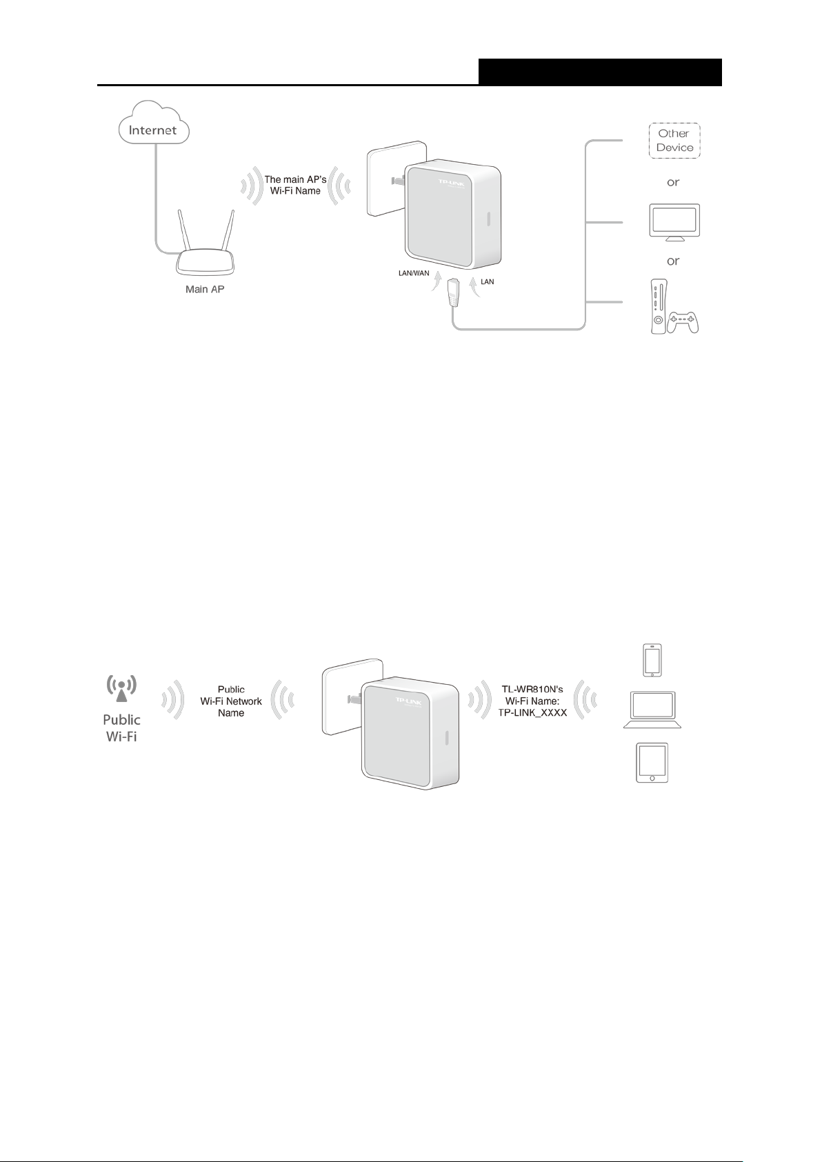
In Hotspot Router mode, TL-WR810N enables multiple users to share Internet connection from
WISP.
In this mode, the LAN port devices share the same IP from WISP through Wireless port. While
connecting to WISP, the Wireless port works as a WAN port at Hotspot Router mode. The
Ethernet port acts as a LA N port .
Figure 2-5 Hardware Installation of the TL-WR810N in Hotspot Router Mode
1. Pl ug t he r out er into an electrical outlet within the ran ge of the Public Wi-Fi.
2. Connect your device to the router wirelessly or via an Ethernet cable. The Wi-Fi network
name and password are on the router’s label.
- 8 -
Page 25
TL-WR810N
300Mbps Wirel ess N Mini Router
Chapter 3. Quick Installation Guide
This chapter will show you how to configure the basic functions of your TL-WR810N 300Mbps
Wireless N Mini Router using Quick Setup Wizard within minutes.
3.1 TCP/IP Configuration
The default domain name of the TL-WR810N 300Mbps Wireless N Mini Router is
http://tplinkwifi.net, the default IP address is 192.168.0.254, and the default Subnet Mask is
255.255.255.0. These values can be changed as you desire. In this guide, we use all the default
values for description.
Connect the local PC to th e LAN port o f the R outer. And then you can configur e the I P addres s for
your PC as the following st eps:
1) Set up the TCP/IP Protocol in "Obtain an IP address automatically" mode on your PC. If
you need instructions as t o how to do this, please refer to Appendix B: Conf igu r ing the PC
2) Then the built-in DHCP se r ver will assign IP address for the PC.
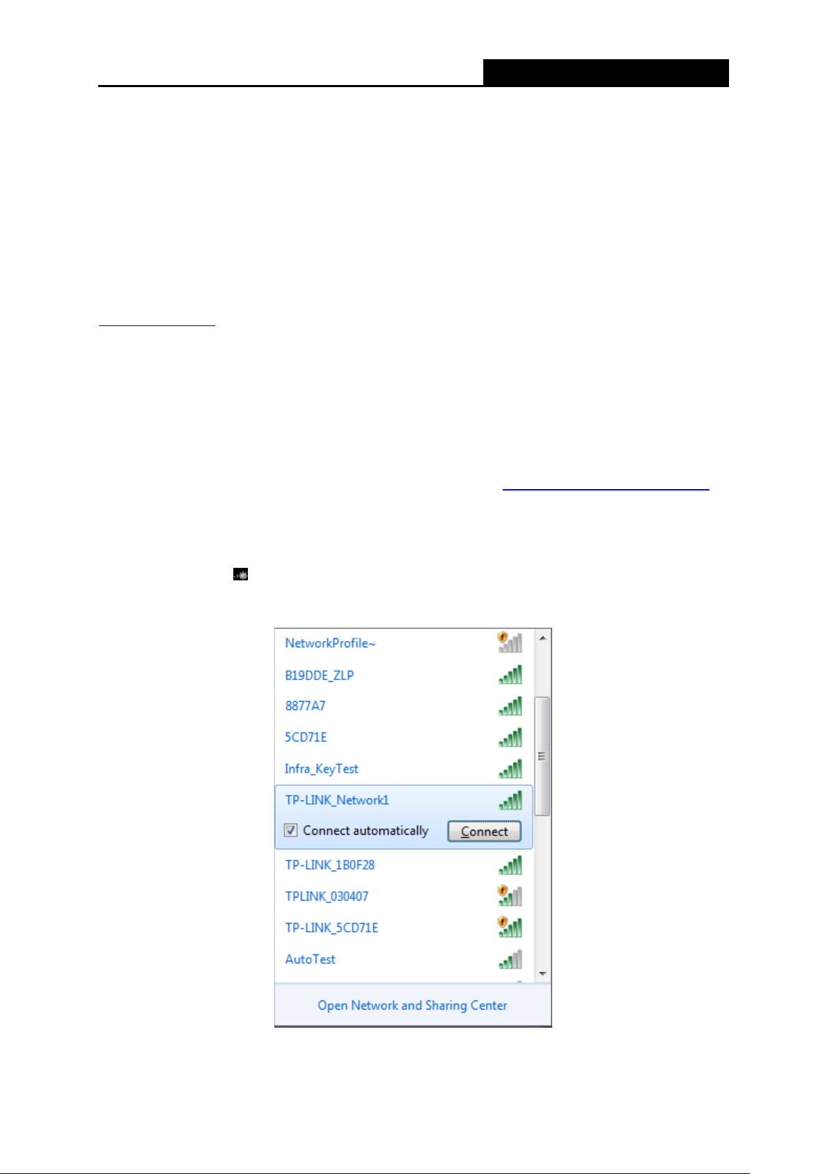
Then connect to the Router t hr ough w ir eless connection following the ste ps below:
1) Cli ck the icon
default SSID of the Router. Click Connect.
at the bottom of your desktop. Click refresh button, and then select the
.
- 9 -
Page 26
TL-WR810N
300Mbps Wirel ess N Mini Router
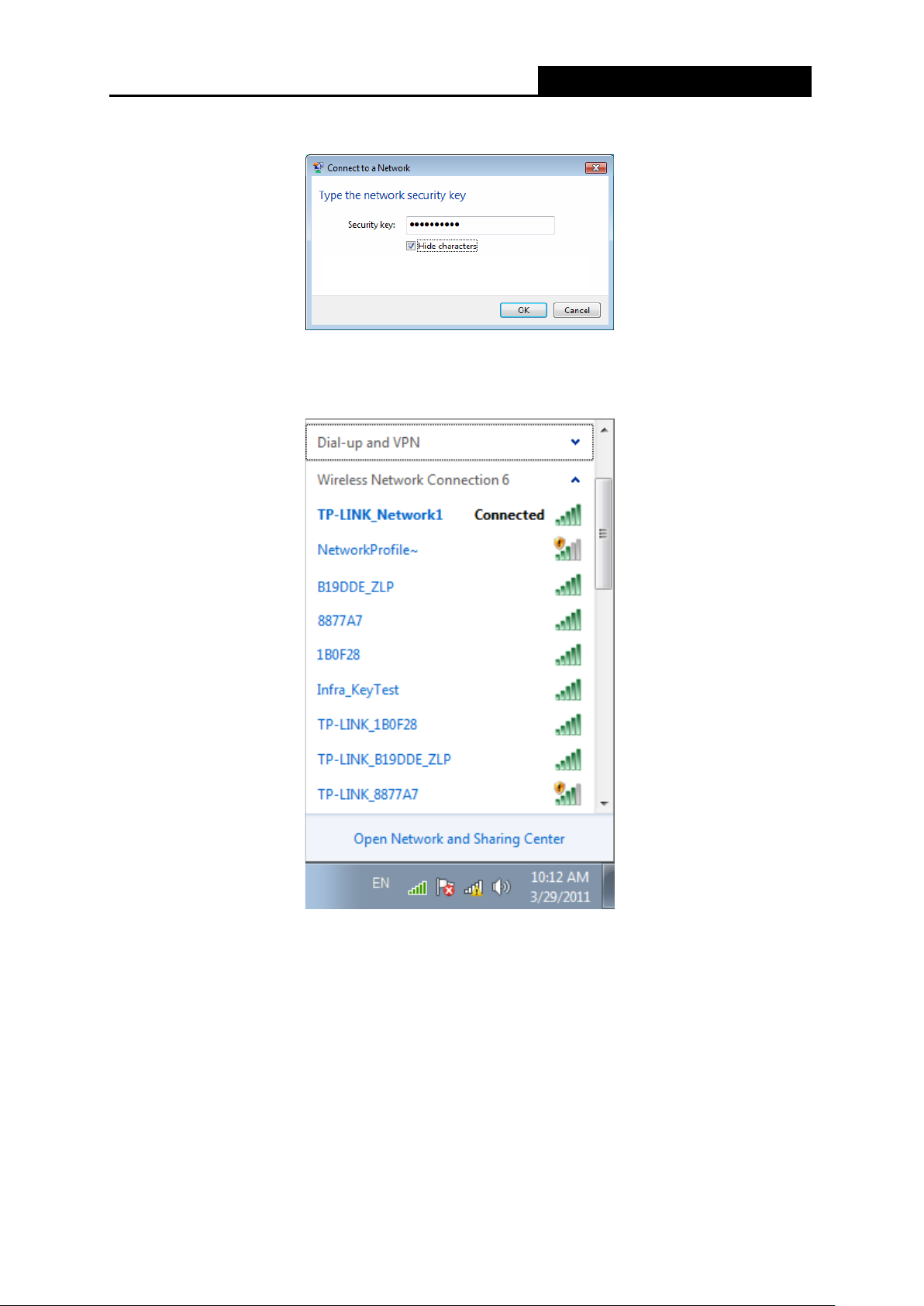
2) Enter the Security key. Click OK.
3) If you can see Connected after the default SSID, you’ve successfully connected to the
wireless network.
Note:
1. The default SSID and Password of your Router are on the label. Both are case-sensitive.
2. The pre-encryption function is enabled by default and the default Network key/Security key
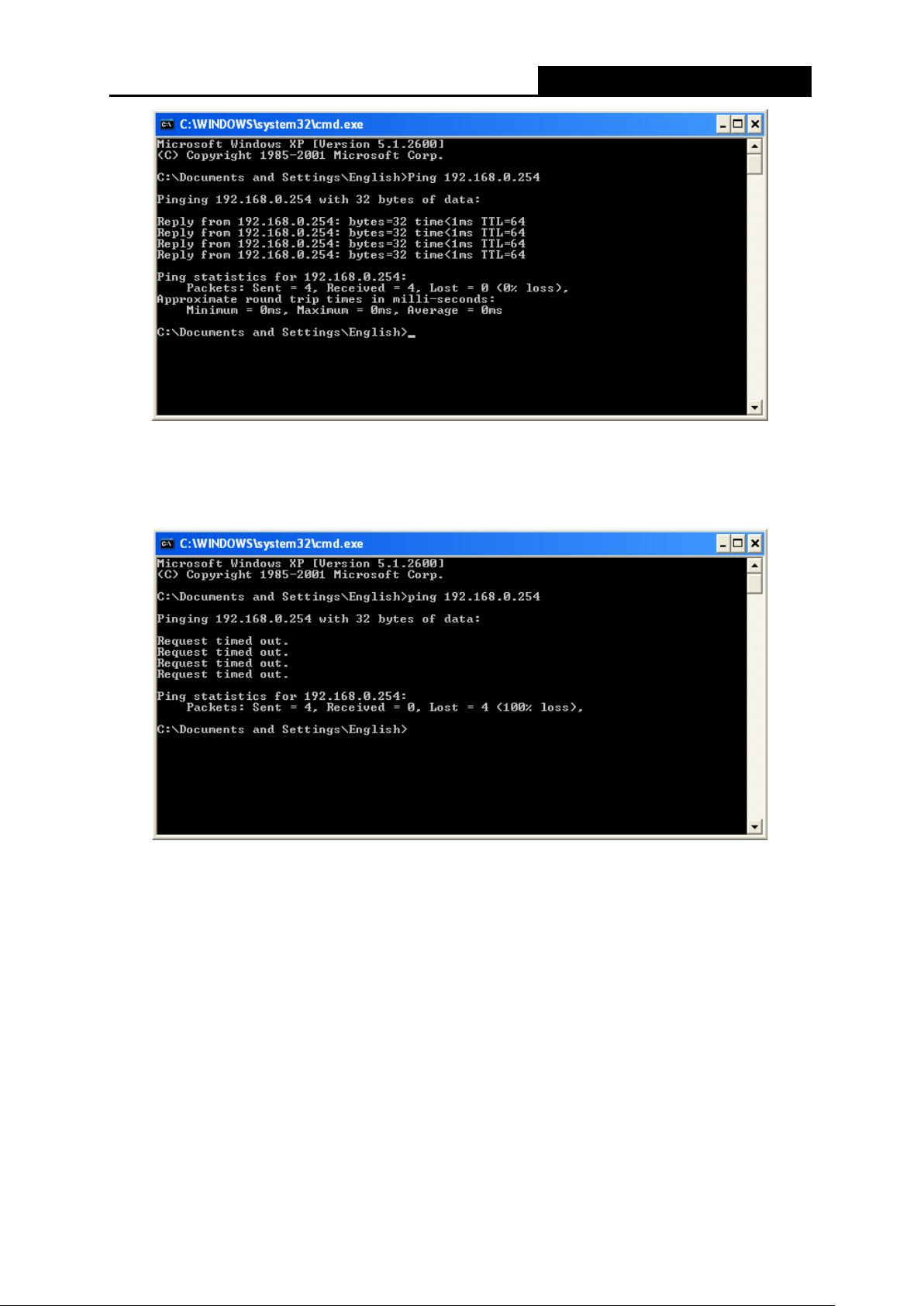
Now, you can run the Ping command in the command prompt to verify the network connection
between your PC and the Router. The following example is in Windows XP.
Open a command prompt, and t ype ping 192.168.0.254, and then press Enter.
If the result displayed is similar to the Figure 3-1, i t means the connection between your PC
is the Password on the label.
and the Router has been est ablished well.
- 10 -
Page 27
TL-WR810N
300Mbps Wirel ess N Mini Router
Figure 3-1 Success result of Ping command
If the result displayed is similar to the Figure 3-2, it means the connection between your PC
and the Router has failed.
Figure 3-2 Failure result of Ping command
Please check the connection following these steps:
1. I s the connection between your PC and the Router correct?
2. I s the TCP/IP configuration for your PC correct?
Note:
If the Router's IP address is 192.168.0.254, your PC's IP address must be within the range of
192.168.0.1 ~ 192.168. 0.253.
- 11 -
Page 28

TL-WR810N
300Mbps Wirel ess N Mini Router
3.2 Quick Installation Guide
With a Web-based utility, it is easy to configure and manage the TL-WR810N 300Mbps Wireless
N Mini Router. The Web-based ut ility can be us ed o n any Windows, Macintosh or UNIX OS wit h a
Web browser, such as Microsoft I nternet Explorer, M ozilla Firefox or Ap ple Safari.
1. To access the configuration utility, open a web-browser and type in the default address
http://tplinkwifi.net in the address field of the browser.
After a moment, a login window will appear, si milar to the Figure 3-3. Enter admin for the
User Name and Password, both in lower case letters. Then click the Login button or press
the Enter key.
Figure 3-3 Login Windows
Note:
If the above screen does not pop-up, it means that your Web-browser has been set to a proxy. Go
to Tools menu > Internet Options > Connections > LAN Settings, in the screen that appears,
cancel the Using Proxy checkbox, and click OK to finish it.
2. A ft er a suc cess ful log in, y ou can clic k the Quick Setup menu t o qu ickly confi gur e your Router.
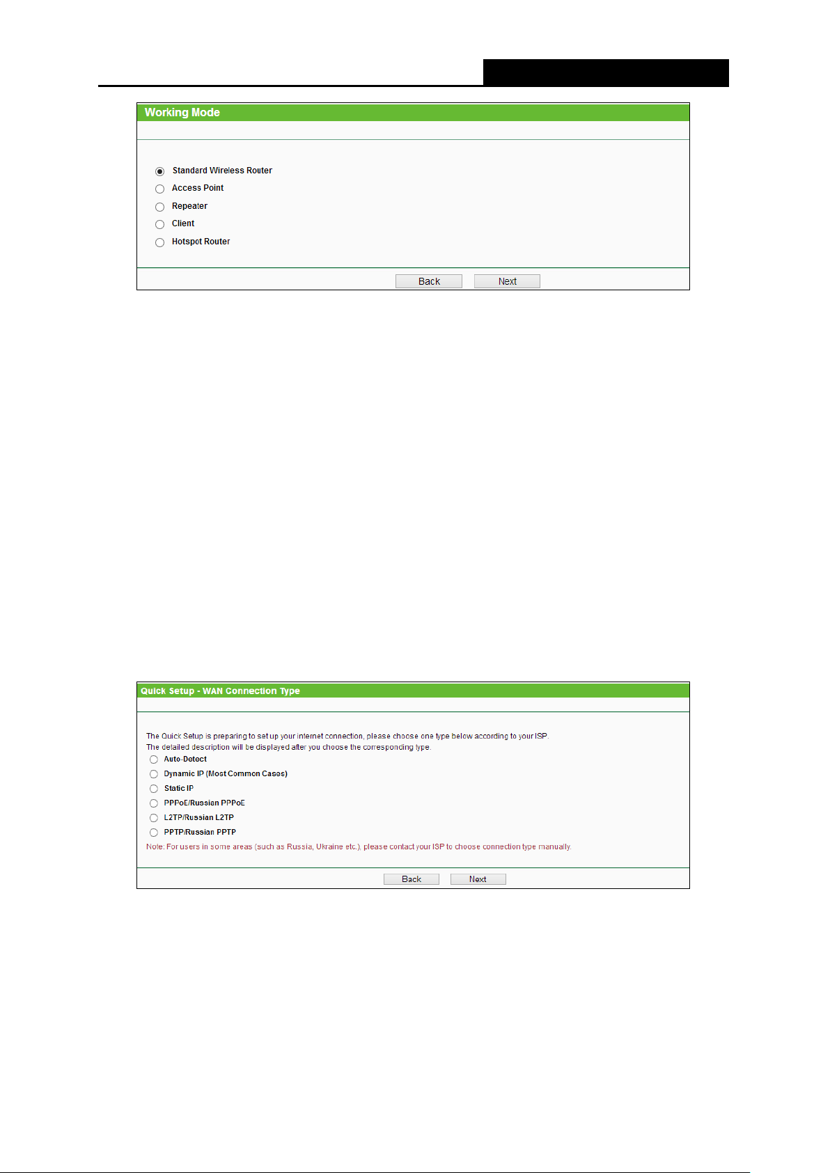
Click Next in Figure 3-4, and you can choose the Working Mode in Figure 3-5.
Figure 3-4 Quick Setup
- 12 -
Page 29
TL-WR810N
300Mbps Wirel ess N Mini Router
Figure 3-5 Quick Setup - Working Mode
Note:
The Router supports five working modes for multi-user to access the Internet: Standard Wireles s
Router, Access Point, Repeater, Client and Hotspot R outer. In Standard Wireless Router
mode, the device enables mu ltiple u sers t o share the I nternet connecti on via A DSL/C able M odem .
In Access Point mode, this device can be connected to a wired network and transform the wired
access into wireless that multiple devices can share together. In Repeater mode, the device will
relay data to an associated main AP. In Client mode, the device will act as a wireless station to
enable wired host(s) to access AP. In Hotspot Router mode, the device enables multiple us ers to
share Internet connection from WISP. You can configure your device quickly by the following
steps in different modes.
3.2.1 Standard Wireless Router Mode
1. When you select Standard Wireless Router mode in Figure 3-5 and click Next. Then the
WAN Connection Ty pe page will appe ar as shown in
Figure 3-6 Quick Setup - WAN Connection Type
Figure 3-6.
The Router provides Auto-Detect function and supports five popular ways Dynamic IP, Static IP,
PPPoE/Russia PPPoE, L2TP/Russia L2TP and PPTP/Russia PPTP to connect to the Internet.
If you are sure of what kind of c onnectio n type y our ISP prov ides, you can select the v ery type and
click Next to go on configuring. If you are not sure of what kind of connection type your ISP
provides, you can select Auto-Detect and click Next to go on configuring.
- 13 -
Page 30
TL-WR810N
300Mbps Wirel ess N Mini Router
Note:
Auto-Detect function is not suitable for L2TP/Russia L2TP and PPTP/Russ ia PPT P, y ou need t o
specify the connection type manually.
If you select Auto-Detect, the Router will automatically detect the connection type your ISP
provides. Make sure the cable is securely plugged into the WAN port before detection. The
appropriate configuration page will be displayed when an active Internet service is successfully
detected by the Router. Then fol low the instructions to complete the con fi gur ation.
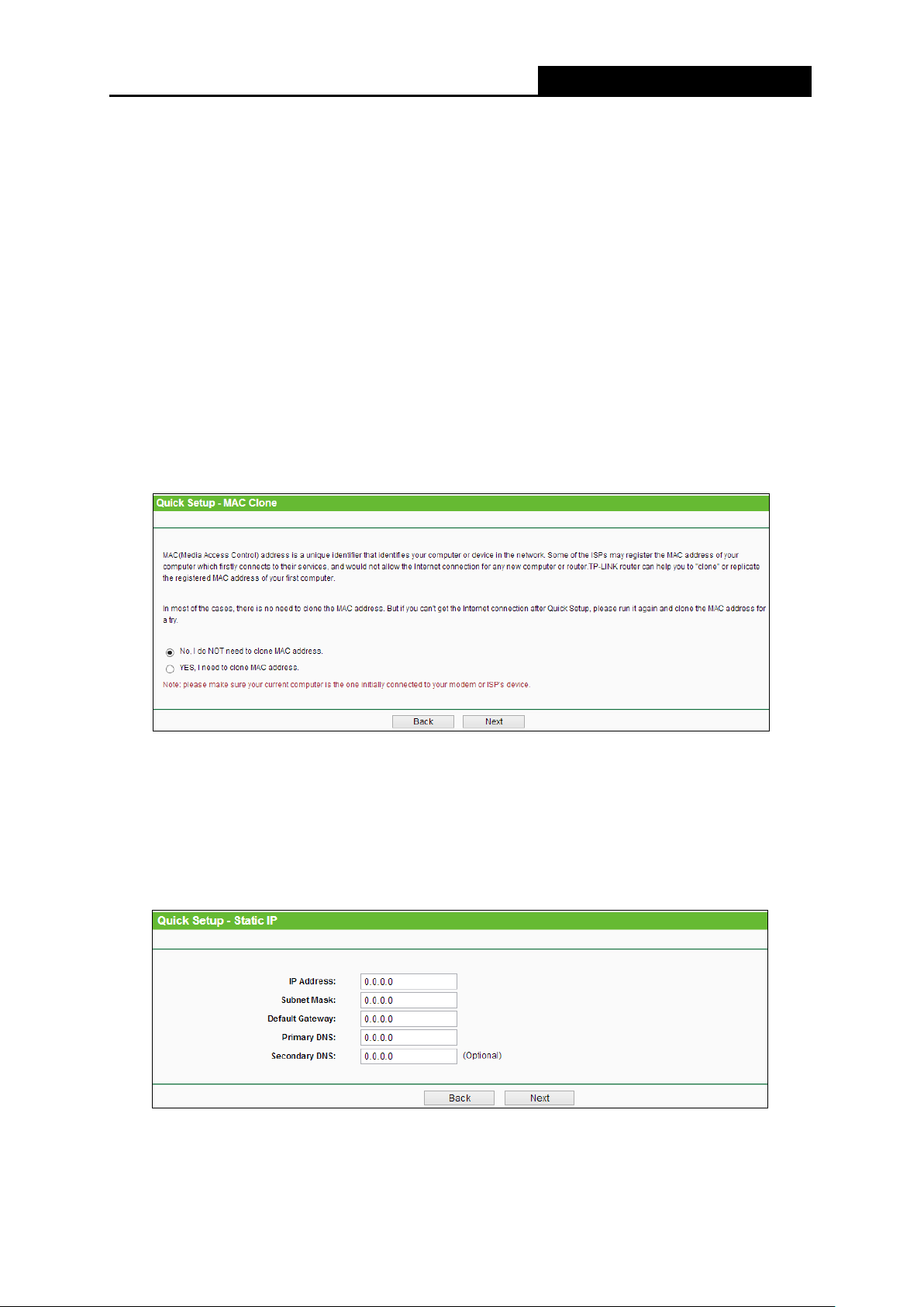
1) If you select Dynamic IP manually, t he next sc reen will appear as shown in Figure 3-7.
In most cases you don’t need to clone the MAC address if you have rebooted the
modem with the new router, please select No, I do NOT need to clone MAC
address.
If you can’t get the Internet connection after Quick Setup, please run it again and
select YES, I need to clo ne MAC address.
Then click Next and Figure 3-12 will appear.
Figure 3-7 Quick Setup - MAC Clone
2) If you select Static IP manually, the next screen will appear as shown in Figure 3-8. This
type of connection uses a permanent, fixed (static) IP address that your ISP assigned. In
this type, you should fill in the IP Address, Subnet Mask, Default Gateway, and DNS IP
address manually, which are specified by your ISP. Then click Next and proceed to Figure
3-12.
Figure 3-8 Quick Setup - Static IP
3) If you select PPPoE/Russia PPPoE manually, the next screen will appear as shown in
- 14 -
Page 31

TL-WR810N
300Mbps Wirel ess N Mini Router
Figure 3-9.
Figure 3-9 Quick Setup - PPPoE
User Name/Password - Enter the User Name and Password provided by your
ISP. These fields are case sensitive. If you have difficulty with this process, please
contact your ISP.
Confirm Password - Re-enter the password provided by your ISP to ensure the
Password you entered is correct. If the Password is different from the Confirm
Password, the screen will appear as shown below. Click OK, and re-enter the
Password and Confirm Password.
4) If you select L2TP/Russian L2TP or PPTP/Russian PPTP manually, the next screen will
appear as shown in Figure 3-10 and Figure 3-11.
Figure 3-10 Quick Setup - L2TP/Russian L2TP
- 15 -
Page 32

TL-WR810N
300Mbps Wirel ess N Mini Router
Figure 3-11 Quick Setup - PPTP/Russian PPTP
User Name/Password - Enter the User Name and Password provided by your ISP.
These fields are case sensitive. If you have difficulty with this process, please contact
your ISP.
Dynamic IP/Static IP - Select Static IP if IP addr ess, subnet mask, gateway and DNS
server address have been pr ovided by your ISP. Otherwise, please select Dynamic IP.
Server IP Address/Name - Enter server IP address or domain name provided by your
ISP.
2. Then, the Wireless page will appear as shown in
Figure 3-12. Set the wireless parameters. It
is recommended that you rename an SSID, choose a Security Type and enter a Password.
Then click Next.
Wireless Radio - Enable or disable the wireless radio choosing from the pull-down list.
Wireless Network Name - Enter a string of up to 32 characters. The same name of
SSID (Service Set Identification) must be assigned to all wireless devices in your
Figure 3-12 Quick Setup - Wireless
- 16 -
Page 33

TL-WR810N
300Mbps Wirel ess N Mini Router
network. The default SSID is set to be TP-LINK_XXXX (XXXX indicates the last unique
four numbers of each Router’s MAC address). But it is recommended strongly that you
change your networks name (SSID) to a different value. This value is ca se-sensitive.
For example, TEST is NOT the same as test.
Disable Security - The wireless security function can be enabled or disabled. If
disabled, the wireless stat ions w ill be ab le to c onn ect the Router without encryption. It is
recommended strongly that you choose one of following opt ion s to enable security.
WPA-PSK/WPA2-PSK - Select WPA based on pre-shared passphrase.
PSK Password - You can ent er ASCII or Hexadecimal characters.
For ASCII, the key can be made up of any numbers 0 to 9 and any letters A to Z, the
length should be between 8 and 63 characters.
For Hexadecimal, t he key can be ma de u p of any numbers 0 to 9 and let ters A to F,
the length should be betw een 8 and 64 characters.
Please also note the key is case sensitive, this means that upper and lower case
keys will affect the outcome. It would also be a good idea to write down the key and
all related wireless security settings.
No Change - If you chose this option, w ireless security configuration will not change!
More Advanced Wireless Settings - If you check this option, you can set the
configuration of Mode, Channel and Channel Width.
Mode - This field determines the wireless mode which the Router works on.
Channel Width - The bandwidth of the wireless channe l.
Channel - This field determines which operating frequency will be used. It is not
necessary to change the w irele ss c hannel unless you notice interference problems with
another nearby access point. If you select auto, then t he AP will select the best channel
automatically.
These settings are only for basic wireless parameters. For advanced sett ings, please refer to
4.7 Wireless
.
3. The Finish page is shown as Figure 3-13. Click the Finish button to make your wireless
configuration take e ffect and finish the Quick Setup.
Figure 3-13 Quick Setup - Finish
- 17 -
Page 34

TL-WR810N
300Mbps Wirel ess N Mini Router
3.2.2 Access Point Mode
1. When you select Access Point mode in Figure 3-5 and click Next. Then the Wireless Setting
page will appear as shown in Figure 3-14.
Figure 3-14 Quick Setup - Wireless Setting
Wireless Network Name - Enter a string of up to 32 characters. The same name of
SSID (Service Set Identification) must be assigned to all wireless devices in your
network. The default SSID is set to be TP-LINK_XXXX (XXXX indicates the last unique
four numbers of each Router’s MAC address). But it is recommended strongly that you
change your networks name (SSID) to a different value. This value is ca se-sensitive.
For example, TEST is NOT the same as test.
Channel - This field determines which operating frequency will be used. The default
channel is set to Auto. It is not necessary to change the wireless channel unless you
notice interference probl ems with another nearby access point.
Wireless Security Mode - This option should be chosen according to the security
configuration of the AP you want to access. It is recommended that the security type is
the same as your AP’s securit y type.
Wireless Password - Input the password of your broadcast SSID.
- 18 -
Page 35

TL-WR810N
300Mbps Wirel ess N Mini Router
2. Click the Next button. You will see the Network Setting page as shown in Figure 3-15. You
can configure the IP parameters of LAN on this page.
Figure 3-15 Quick Setup - Network Setting
Type - Select the LAN IP type of the router or you can set Smart IP as the default
setting for most cases.
IP Address - Enter the IP address of your system in dotted-decimal notation (factory
default: 192.168.0.254).
Subnet Mask - An address code that determines the size of the network. Normally
255.255.255.0 is used as t he subnet mask.
DHCP Server - Enable or Disable the server. If you disable the Server, you must have
another DHCP server within your network or else you must configure the IP address of
the computer manually.
Note:
If you change the IP address, you must use the new IP address to login the system.
3. Click the Next button. You will see the Finish page as shown in Figure 3-16. Click the
Reboot button to fin ish t he Quick Setup.
3.2.3 Repeater Mode
1. When you select Repeater mode in Figure 3-5 and click Next. Then the Wireless Repeater
page will appear as shown in Figure 3-17.
Figure 3-16 Quick Setup - Finish
- 19 -
Page 36

TL-WR810N
300Mbps Wirel ess N Mini Router
Figure 3-17 Quick Setup - Wireless Setting
Wireless Name of Ro ot AP - The SSI D of AP that you want to access.
MAC Address of Root AP - The MAC address of AP that you want to access.
Survey - Click this button, you can search the AP which runs in the env ironment.
WDS Mode - This field determines which WDS Mode will be used. It is not necessar y to
change the WDS Mode unless you notice network communication problems with root
AP. If you select Auto, then Router will choose the appropriate WDS Mode
automatically.
Wireless Security Mode - This option should be chosen according to the security
configuration of the AP you want to access. It is recommended that the security type is
the same as your AP’s securit y type.
Wireless Password - If the AP your router is going to connect need password, you
need to fill the password in t his bl ank.
2. Click Survey button on the Wireless p age as sh own in Figure 3-17, and then AP L ist p age w il l
appear as shown in Figure 3-18. Find the SSID of the Access Point you want to access, and
click Connect in the corresponding row. For example, the third item is selected. The target
network’s SSID will be automatically filled into the corresponding box which is shown as the
Figure 3-17.
- 20 -
Page 37

TL-WR810N
300Mbps Wirel ess N Mini Router
Figure 3-18 AP List
Note:
If you know the SSID of the desired AP, you can also input it into the field "SSID" manually.
3. Click the Next button. You will see the Network Setting page as shown in Figure 3-19. You
can configure the IP parameters of LAN on this page.
Figure 3-19 Quick Setup - Network Setting
Type - Select the LAN IP type of the router or you can set Smart IP as the default
setting for most cases.
IP Address - Enter the IP address of your system in dotted-decimal notation (factory
default: 192.168.0.254).
Subnet Mask - An address code that determines the size of the network. Normally
255.255.255.0 is used as t he subnet mask.
DHCP Server - Enable or Disable the server. If you disable the Server, you must have
another DHCP server within your network or else you must configure the IP addr e ss of
the computer manually.
Note:
If you change the IP address, you must use the new IP address to login the system.
- 21 -
Page 38

TL-WR810N
300Mbps Wirel ess N Mini Router
4. Cl ick the Next button. You will see the Finish page as shown in Figure 3-20. Click the Reboot
button to make your wireles s configuration take effe ct and finish the Quick Setup.
Figure 3-20 Quick Setup - Finish
3.2.4 Client Mode
1. When you select Client mode in Figure 3-5 and click Next. Then the Wireless Setting page
will appear as shown in Figure 3-21.
Figure 3-21 Quick Setup - Wireless Setting
Wi r el ess Name of Root AP - Enter the SSID that you want to access.
MAC Address of Root AP - Enter the MAC address of AP that you want to access.
Survey - Click this button, you can survey the AP which runs in the environment.
Wireless Security Mode - This option should be chosen according to the security
configuration of the AP you want to access. It is recommended that the security type is
the same as your AP’s security type.
Wireless Password - If the AP y our router is going to connect need p asswor d, y ou need
to fill the password in this bla nk.
2. Click Survey button on the Wireless p age as sh own in Figure 3-21, and then AP L ist p a ge wi ll
appear as shown in Figure 3-22. Find the SSID of the Access Point you want to access, and
click Connect in the corresponding row. For example, the third item is selected. The target
- 22 -
Page 39

TL-WR810N
300Mbps Wirel ess N Mini Router
network’s SSID will be automatically filled into the corresponding box which is shown as the
Figure 3-21.
Figure 3-22 AP List
3. Click the Next button. You will see the Network Setting page as shown in Figure 3-23. You
can configure the IP parameters of LAN on this page.
Figure 3-23 Quick Setup - Network Setting
Type - Select the LAN IP type of the router or you can set Smart IP as the default
setting for most cases.
IP Address - Enter the IP address of your system in dotted-decimal notation (factory
default: 192.168.0.254).
Subnet Mask - An address code that determines the size of the network. Normally
255.255.255.0 is used as t he subnet mask.
DHCP Server - Enable or Disable the server. If you disable the Server, you must have
another DHCP server within your network or else you must configure the IP address of
the computer manually.
Note:
If you change the IP address, you must use the new IP address to login the system.
- 23 -
Page 40

TL-WR810N
300Mbps Wirel ess N Mini Router
4. Click the Next button. You will then see the Finish page. Click the Reboot button to make
your wireless configurati on take effect and finish the Quick Setup.
Figure 3-24 Quick Setup - Finish
Note:
The operating distance or range of your wireless connection varies significantly based on the
physical placement of the Router. For best results, place your Router.
Near the center of the area in which your wireless stations will operate.
In an elevated location such as a high sh el f.
Away from the potential sources of interference, such as PCs, microw aves, and cordle ss
phones.
Away from large metal surfaces.
Failure to follow these guidelines can result in significant performance degradation or inability to
wirelessly connect to the Router.
3.2.5 Hotspot Router Mode
1. When you select Hotspot Router mode in Figure 3-5 and click Next. Then the WAN
Connection Type page will appear as shown in Figure 3-25.
Figure 3-25 Quick Setup - WAN Connection Type
The Router supports five popular ways Dynamic IP, Static IP, PPPoE/Russian PPPoE,
L2TP/Russian L2TP and PPTP/Russian PPTP to connect to the Internet. To make sure the
connection type your ISP provides, please refer to the ISP. Make sure the cable is securely
plugged into the W A N port before detection.
- 24 -
Page 41

TL-WR810N
300Mbps Wirel ess N Mini Router
Dynamic IP - Your ISP uses a DHCP service to assign your Router an IP address for
connecting to the Internet. When the Router connects to a DHCP server, or the ISP
supplies you with DHCP connection, please choose this type. If you choose this type of
connection, no configuration should be set and you can go on with the wireless
configuration in
Figure 3-30.
Static IP - In this type, you should fill in the IP address, Subnet Mask, Default Gateway,
and DNS IP address manually, which are specified by your ISP. Then click Next and
proceed to Figure 3-30.
Figure 3-26 Quick Setup - Static IP
PPPoE/Russian PPPoE - If you have applied ADSL to realize Dial-up service, you
should choose this type. Under this condition, you should fill in both the User Name and
Password that the ISP supplied. Then click Next and proceed to Figure 3-30.
L2TP/Russian L2TP - In this type, you should fill in the username, password and IP
address/Domain name of VP N S er ver. Then click Next and procee d t o Fi gur e 3-30.
Figure 3-27 Quick Setup - PPPoE
- 25 -
Page 42

TL-WR810N
300Mbps Wirel ess N Mini Router
Figure 3-28 Quick Setup - L2TP
PPTP/Russian PPTP - In this type, you should fill in the username, password and IP
address/Domain name of VP N S er ver. Then click Next and procee d t o Fi gur e 3-30.
Figure 3-29 Quick Setup - PPPTP
2. You can configure the basic settings for t he wireless network on this page.
Figure 3-30 Quick Setup - Wireless
- 26 -
Page 43

TL-WR810N
300Mbps Wirel ess N Mini Router
SSID - The SSID of the AP your router is goi ng to conne ct to as a c lient. Y ou can also us e
the search function to select the SSID to join.
BSSID - The BSSID of the AP your router is goin g t o connect to as a client. You can also
use the search function to select the BSSID to join.
Survey - Click this button, you can survey the AP which runs in the current channel.
Key t yp e - This option should be chosen according to the AP's security configuration. It
is recommended that the security type is the same as your AP's security type.
WEP Index - This option should be chosen if the key ty pe is WEP ( ASCII) or WEP (HEX) .
It indicates the index of the WEP key.
Auth type - This option sh ould be chos en if the key type is WEP ( ASCII ) or WEP (HEX ).It
indicates the authorizat ion type of the Root AP.
Password - If the AP y our rout er is going t o conne ct needs password, you need to fill the
password in this blan k.
Local SSID - Enter a value of up to 32 characters. The same Name (SSID) must be
assigned to all wireless devices in your network.
Wireless Security Mode - You can configure the security settings of your wireless
network.
Wireless Password - Input the password of y our Local SSID.
3. Click Survey button on the Wireless page as sh ow n in Figure 3-30 and then AP List pa ge w ill
appear as shown in Figure 3-31. Find the SSID of the Access Point you want to access, and
click Connect in the corresponding row. For example, the third item is selected. The target
network’s SSID will be automatically filled i nto the corresponding box which is shown as the
Figure 3-30. Then click Next.
Figure 3-31 AP List
- 27 -
Page 44

TL-WR810N
300Mbps Wirel ess N Mini Router
4. The Finish page is shown as Figure 3-32. Click the Reboot button to make your wireless
configuration take e ffect and finish the Quick Setup.
Figure 3-32 Quick Setup - Finish
Note:
The operating distance or range of your wireless connection varies significantly based on the
physical placement of the Router. For best results, place your Router.
Failure to follow these guidelines can result in significant performance degradation or inability to
wirelessly connect to the Router.
Near the center of the area in which your wireless stations will operate.
In an elevated location such as a high sh el f.
Away from the potent ial sources of inter ference, such as PCs, micr owaves, and cord less
phones.
Away from large metal surfaces.
- 28 -
Page 45

TL-WR810N
300Mbps Wirel ess N Mini Router
Chapter 4. Configuration for Standard Wireless Router Mode
This chapter will show each Web page's key functions and the configuration way for Standard
Wireless Router Mode of TL-WR810N.
4.1 Login
After your successful login, you can configure and manage the device. There are main menus on
the left of the web-based utilit y. Submenus will be available after you clic k one of the main menus.
On the right, there are the cor r esponding explanations and instructi ons.
Figure 4-1
The detailed explanations for each Web page ’s key function are listed below.
4.2 Status
The Status page provides the current status information about the Router on Standard W irel ess
Router Mode. All information is read-only.
- 29 -
Page 46

TL-WR810N
300Mbps Wirel ess N Mini Router
Figure 4-2 Status
Firmware Version - The version information of the Router’s firmware.
Hardware Version - The version infor m at ion of the Router’s hardware.
LAN - This field displays the current settings or information for the LAN, you can configure
them in the Network > LAN page.
• MAC Address - The physical address of the Router, as seen from the LAN.
• IP Address - The LAN IP addr ess of the Router.
• Subnet Mask - The subnet mask associated wit h LAN IP address.
Wireless - This field displays basic information or status for wireless function, you can
configure them in the Wireless > Wireless Settings page.
• Wireless Radio - Indicates whether the wireless radio feature of the AP is enabled or
disabled.
• Name (SSID) - The SSID of the AP.
• Mode - The current w ireless mode which the Router works on.
• Channel Width - The current wireless channel width in use.
- 30 -
Page 47

TL-WR810N
300Mbps Wirel ess N Mini Router
• Channel - The current wireless channel in use.
• MAC Address - The physical address of the Router, as seen from the WLAN.
• WDS Status - The status of WDS connection.
WAN - This field displays the current settings or information for the WAN, you can configure
them in the Network > WAN page.
• MA C Address - The physical address of the WAN port, as seen from the Internet.
• IP Address - The current WA N (Internet) IP Address. This fiel d will be bl ank or 0.0. 0.0 if the
IP Address is assigned dynamically and there is no connection to t he I nt ernet.
• Subnet Mask - The subnet mask associated with the WAN IP Address.
• D efault Gateway - The Gateway currently used by the Router is shown here. When you
use Dynamic IP as the connection Internet type, the Renew button will be displayed here.
Click the Renew Button to obtain new IP parameters dynamically from the ISP. And if you
have got an IP address, Release button will be displayed here. Click the Release button to
release the IP address t he Router has obtained from the I SP.
• DNS Server - The DNS (Domain Name System) serv er I P addr esse s current ly used by the
Router.
Traffic Statist i cs - The Router’s traffic statistics.
• Recei ved (Bytes) - T raf fic that count ed in byt es has been rece ived out fro m the WA N port .
• R eceived (Packets) - Traffic that counted in packets has been received out from the WAN
port.
• Sent (Bytes) - Traffic that counted in by tes has been sent out from the WAN port.
• Sent (Packets) - Traffic that counted in packet s has been sent out from the WAN port.
System Up Time - The length of the time since the Router was last powered on or reset.
Click the Refresh but t on t o get the latest status and settings o f the R outer.
4.3 Quick Setup
Please refer to Section 3.2: Q uic k Installation Guide.
4.4 WPS
WPS (Wi-Fi Protected Setup) can help you to quickly and securely connect to a network. This
section will guide you to a dd a new w ireless d ev ice to an exi stin g netw ork qu ickly by function. The
WPS function is o nly available when the Operation Mode is set to Access Point. Select menu
“WPS”, you will see the next screen s how n in Figure 4-3.
- 31 -
Page 48

TL-WR810N
300Mbps Wirel ess N Mini Router
Figure 4-3 WPS
WPS Status - To enable or disable the WPS function her e.
Current PIN - The current value of the device's PIN is displayed here. The def ault PIN of the
device can be found in the labe l or User Guide.
Restore PIN - Restore the PIN of the device to its default.
Gen New PIN - Click this button, and then you can get a new random value for the device's
PIN. You can ensure the network security by generating a new PIN.
Disable PIN of this Device - WPS external registrar of entering the device’s PIN ca n be
disabled or enabled manually. If the device receives multiple failed attempts to authenticate
an external Registrar, this function will be disabled automatically.
Add Device - You can add a new device to the existing network manually by clicking this
button.
To add a new device:
If the wireless adapter supports Wi-Fi Protected Setup (WPS), you can establish a wireless
connection between wireless adapter and device using either Push Button Configuration (PBC)
method or PIN method.
Note:
To build a successful connection by WPS, you should also do the corresponding configuration of
the new device for WPS function meanw hile.
For the configuration of the new device, here takes the Wireless Adapter of our company for
example.
I. By PBC
If the wireless adapter supports Wi-Fi Protected Setup and the Push Button Configuration (PBC)
method, you can add it to the net work by PBC with the following two methods.
Method One:
Step 1: Keep the WPS Status as Enabled and click the Add Device button in Figure 4-3, then
the following screen will a ppear.
- 32 -
Page 49

TL-WR810N
300Mbps Wirel ess N Mini Router
Figure 4-4 Add A New Device
Step 2: Choose “Press the button of the new device in two minutes” and click Connect.
Step 3: For the configuration of the wireless adapter, please choose “Push the button on my
access point or wireless router” in the configuration utility of the WPS as below, and
click Connect.
The WPS Configuration Screen o f Wireless Adapter
Step 4: Wait for a while until the next screen appears. Click OK to complete the WPS
configuration.
The WPS Configuration Screen o f Wireless Adapter
- 33 -
Page 50

TL-WR810N
300Mbps Wirel ess N Mini Router
Method Two: Enter the PIN into my AP
Step 1: For the configuration of the wireless adapter, please choose “Enter the PIN of this
device into my access poi nt or wireless router” in the configuration utility of the WPS
as below, and click Connect.
The WPS Configuration Screen o f Wireless Adapter
Note:
In this example, the default PI N c ode of this adapter is 16952898 as the above figure shown.
Step 1: Keep the WPS Stat us as Enabled and click the Add Device button in Figure 4-3.
Step 2: Choose “Enter the new device's PIN” and enter the PIN code (take 16952898 for
Method Three: Ent er the PIN from my AP
example) of the wireless adapter in the field after PIN as sh own in the figure below. Then
click Connect.
Figure 4-5 Add A New Device
Step 3: Get the Current PIN code of the AP in Figure 4-3 (each AP ha s it s un ique PI N c ode. H ere
takes the PIN code 12345670 of this AP for example).
Step 4: For the configuration of the wireless adapter, please choose “Enter the PIN of my
access point or wireless router” in the configuration utility of the WPS as below, and
enter the PIN code of the AP into the field after “A ccess P oint PI N”. Then click Connect.
- 34 -
Page 51

TL-WR810N
300Mbps Wirel ess N Mini Router
The WPS Configuration Screen o f Wireless Adapter
Note:
The default PIN code of the AP can be found in its label or the WPS configuration screen as
Figure 4-3.
You will see the Connect successfully screen when the new device has successfully connected
to the network.
Note:
1) The WPS LED on the AP will light green for five minutes if the device h as been successfully
added to the network.
2) The WPS function cannot be configured if the Wireles s fu nction of the AP is disabled. Please
make sure the Wireless funct ion is enabled before configuring the WPS.
4.5 Working Mode
Please select one mode you want. Click Save to save your choice, which is shown as Figure 4-6.
Standard Wireless Router - In this mode, the device enables multiple users to share the
Internet connection via ADSL/Cable Modem. The LAN devices share the same IP from ISP
through Wireless port. While connecting to Internet, the LAN/WAN Ethernet port works as a
WAN port at Standard Wireless Router mode.
Figure 4-6 Wireless Working Mode Settings
- 35 -
Page 52

TL-WR810N
300Mbps Wirel ess N Mini Router
Access Point - In this mode, this device can be connected to a wired network and transform
the wired access into wireless t hat mu ltiple dev ices c an share t ogeth er, especially for a home,
office or hotel where only wired network is available.
Repeater - In this mode, this device can copy and reinforce the existing wireless signal to
extend the coverage of the signal, especially for a large space to eliminate signal-blind
corners.
Client - In this mode, this dev ice can be co nnected t o another dev ice via Ether net port and act
as an adaptor to grant y our wired dev ic es acc ess t o a wirel ess n etwor k, especially for a Smart
TV, Media Player, or game console only w ith an Et hernet port.
Hotspot Rout er - In this mode, the device enab les multi ple users to shar e Inter net connect ion
from WISP. The LAN port devices share the same IP from WISP through Wireless port. While
connecting to WISP, the Wireless port works as a WAN port at Hotspot Router mo de. The
Ethernet port acts as a LA N port .
4.6 Network
Figure 4-7 The Network menu
There are three submenus under the Network menu (shown in Figure 4-7): WAN, MAC Clone
and LAN. Click any of them, and you will be able to configure the corresponding function.
4.6.1 WAN
Choose menu “Network → WAN”, and then you can configure t he IP parameters of the WAN on
the screen below.
1. If your ISP provides the DHCP service, please choose Dynamic IP type, and the Router will
automatically get IP parameter s fro m your ISP. You can see the page as follow (Figure 4-8):
- 36 -
Page 53

TL-WR810N
300Mbps Wirel ess N Mini Router
Figure 4-8 WAN - Dynamic IP
This page displays the WAN IP parameters assigned dynamically by your ISP, including IP
address, Subnet Mask, Default Gateway, etc. Click the Renew button to renew the IP
parameters from your ISP. Click the Release button to release the IP parameters.
MTU Size - The normal MTU (Maximum Transmission Unit) value for most Ethernet
networks is 1500 Bytes. It is not recommended that you change the default MTU Size
unless required by your I SP.
Use These DNS Servers - If your ISP gives you one or two DNS addresses, select Use
These DNS Servers and enter the primary and secondary addresses into the correct
fields. Otherwise, the DN S servers will be assigned dynamically fro m y our I SP.
Note:
If you find error when you go to a website after entering the DNS addresses, it is likely that
your DNS servers are set up improperly. You should contact your ISP to get DNS server
addresses.
Host Name - This option specifies the Host Na m e of the Router.
Get IP with Unicas t DHCP - A few ISPs' DHCP servers do not support the broadcast
applications. If you cannot get the IP Address normally, you can choose this option. (It is
rarely required.)
Click the Save button to save your settings.
2. If your ISP provides a static or fixed IP A ddress, Subnet Mask, Default Gateway and DNS
setting, select Static IP. The Static IP settings page will appear as show n in Figure 4-9.
- 37 -
Page 54

TL-WR810N
300Mbps Wirel ess N Mini Router
Figure 4-9 WAN - Static IP
IP Address - Enter the IP address in dotted-decimal notation provided by your ISP.
Subnet Mask - Enter the subnet Mask in dotted-decimal notation provided by your ISP,
usually is 255.255.255.0.
Default Gateway - Enter the gateway IP address in dot ted-decimal notation provided by
your ISP.
MTU Size - The normal MTU (Maximum Transmission Unit) value for most Ethernet
networks is 1500 Bytes. It is not recommended that you change the default MTU Size
unless required by your I SP.
Primary/Secondary DNS - (Optional) Enter one or two DNS addresses in
dotted-decimal not at ion provided by your ISP.
Click the Save button to save your settings.
3. If your ISP provides a PPPoE connection, select PPPoE/Russia PPPoE option. Then you
should enter the following parameters (Figure 4-10):
- 38 -
Page 55

TL-WR810N
300Mbps Wirel ess N Mini Router
Figure 4-10 WAN - PPPoE/Russia PPPoE
User Name/Password - Enter the User Name and Password provided by your ISP.
These fields are case-sensitive.
Confirm Password - Enter again the Password provided by your ISP to ensure the
password you entered i s correct.
Secondary Connection - It’s available only for PPPoE Connection. If your I SP pr ovides
an extra Connection type such as Dynamic/Static IP to connect to a local area network,
then you can check the radio button of Dynamic/Static IP to activate this secondary
connection.
• Disabled - The Secondary Connection is disabled by default, so there is PPPoE
connection only. This is recommended.
• Dynamic IP - You can check this radio button to use Dynamic IP as the secondary
connection to connect to the local area network provided by ISP.
• Static IP - You can check this radio button to use Static IP as the secondary
connection to connect to t he local area network provided by ISP.
Connect on Demand - In this mode, the Internet connection can be terminated
automatically after a specified inactivity period (Max Idle Time) and be re-established
when you attempt to access the Internet again. If you want your Internet connection
keeps active all the time, please enter “0” in the Max Idle Time field.
the number of minutes you want to have elapsed before your Internet access
disconnects.
Connect Automatically - The connection can be re-established automatically when it
was down.
Otherwise, enter
- 39 -
Page 56

TL-WR810N
300Mbps Wirel ess N Mini Router
Time-based Connecting - The connection w ill only be est abl ished in the per iod fro m the
start time to the end time (both are in HH:MM format).
Note:
Only when you have configured the system time on “System Tools → Time” page, will the
Time-based Connecti ng function can take effect.
Connect Manually - You can click the Connect/Disconnect button to
connect/disconnect im mediately. This mode also supports the Max Idle Time function as
Connect on Demand mode. The Internet connection can be disconnected automatic ally
after a specified inactivity period and re-established when you attempt to access the
Internet again.
Click t he Connect button to connect immediately. Click the Disconnect button to disconnect
immediately.
Caution: Sometimes the connection cannot be terminated although you specify a time to
Max Idle Time because some applications are visiting the Internet continually in the
background.
If you want to do some advanced configurations, please click the Advanced button, and the
page shown in Figure 4-11 will then appear:
Figure 4-11 WAN - PPPoE Advanced Settings
MTU Size - The default MTU size is “1480” bytes, which is usually fine. It is not
recommended that you change the default MTU Size unless required by your ISP.
Service Name/AC Name - The service name and AC (Access Concentrator) name
should not be configured unless you are sure it is necessary for your ISP.
leaving these fields blank will work.
In most cases,
- 40 -
Page 57

TL-WR810N
300Mbps Wirel ess N Mini Router
ISP Specified IP Address - If your ISP does not automatically assign IP addresses to
the Router during login, please click “Use IP address specified by ISP” check box and
enter the IP address pr ovided by your ISP in dotted-decimal notation.
Detect Online Interval - The Router will detect Access Concentrator online at every
interval. The default value is “0”. You can input the value between “0” and “120”. The
value “0” means no detect .
Primary DNS/Secondary DNS - If your ISP does not automatically assign DNS
addresses to the Router during login, please click “Use the following DNS servers”
check box and enter the IP address in dotted-decimal notation of your ISP’s primary
DNS server. If a secondary DNS server addr ess is available, enter it as well.
Click the Save button to save your settings.
4. If your ISP provides BigPond Cable connection, please select BigPond Cable option. Then
you should enter the follow ing parameters (Figure 4-12):
User Name/Password - Enter the User Name and Password provided by your ISP.
These fields are case-sensitive.
Auth Server - Enter the authenticating serv er I P address or host name.
Auth Domain - Type in the domain suffix server name based on your locatio n,
MTU Size - The default MTU size is “1480” bytes, which is usually fine. It is not
recommended that you c hange t he default MTU Size unless required by your ISP.
Connect on Demand - In this mode, the Internet connection can be terminated
automatically after a specified inactivity period (Max Idle Time) and be re-established
Figure 4-12 WAN - BigPond Cable
- 41 -
Page 58

TL-WR810N
300Mbps Wirel ess N Mini Router
when you attempt to access the Internet again. If you want your Internet connection
keeps active all the time, please enter “0” in the Max Idle Time field.
Otherwise, enter
the number of minutes you want to have elapsed before your Internet access
disconnects.
Connect Automatically - The connection can be re-established automatically when it
was down.
Connect Manually - You can click the Connect/Disconnect button to
connect/disconnect im mediately. This mode also supports the Max Idle Time function as
Connect on Demand mode. The Internet connection can be disconnected automatically
after a specified inactivity period and re-established when you attempt to access the
Internet again.
Click t he Connect button to connect immediately. Click the Disconnect button to disconnect
immediately.
Caution: Sometimes the connection cannot be terminated although you specify a time to
Max Idle Time because some applications are visiting the Internet continually in the
background.
Click the Save button to save your settings.
5. If your ISP provides L2TP connection, please select L2TP/Russia L2TP option. Then you
should enter the following par ameters (Figure 4-13):
Figure 4-13 WAN - L2TP/Russia L2TP
- 42 -
Page 59

TL-WR810N
300Mbps Wirel ess N Mini Router
User Name/Password - Enter the User Name and Password provided by your ISP.
These fields are case-sensitive.
Confirm Password - Enter again the Password provided by your ISP to ensure the
password you entered i s correct.
Dynamic IP/ Static IP - Choose either as you are given by your ISP. Click t he Connect
button to connect immediately. Click the Disconnect button to disconnect immediately.
Server IP Address/Name - Enter server IP address or domain name provided by your
ISP.
IP Address - Enter the IP addres s us ed for dial-up. (Only can be configured when Static
IP is selected)
Subnet Mask - Enter the subnet mask provided by your ISP. (Only can be configured
when Static IP is selected)
Gateway - Enter gateway provided by your ISP. (Only can be configured when Static IP
is selected)
DNS - Enter DNS serv er provided by your ISP. (Only can be configur ed when Stat i c IP is
selected)
Internet IP Address - The Internet IP address assigned by L2TP server.
Internet DNS - The Internet DNS server address assigned by L2TP server.
Connect on Demand - You can configure the Router to disconnect from your Internet
connection after a specified period of inactivity (Max Idle Time). If your Internet
connection has been terminated due to inactivity, Connect on Demand enables the
Router to automatically re-establish your connection as soon as you attempt to access
the Internet again. If you wish to activate Connect on Demand, check the radio button.
If you want your Internet connection to remain active at all times, enter 0 in the Max Idle
Time f ield. Otherwise, enter the number of minutes you want to have elapsed before
your Internet connection terminates.
Connect Automatically - Connect automatically after the Router is dis connected. To
use this option, check the r adio button.
Connect Manually - You can configure the Router to make it connect or disconnect
manually. After a specified period of inactivity (Max Idle Time), the Router will
disconnect from your Internet connection, and you will not be able to re-establish your
connection automatically as soon as you attempt to access the Internet again. To use
this option, check the radio button. If you want your Internet connection to remain active
at all times, enter "0" in the Max Idle Time field. Otherwise, ent er t he number of minutes
that you wish to have the Internet connecting last unless a new link is request ed.
Caution: Sometimes the connection cannot be disconnected although you specify a time to
Max Idle Time, because some applications are visiting the Internet continually in the
background.
- 43 -
Page 60

TL-WR810N
300Mbps Wirel ess N Mini Router
Click the Connect button to connect immediately.
Click the Disconnect butt on t o disconnect immediately.
Click the Save button to save your settings.
6. If your ISP provides PPTP connection, please select PPTP/Russia PPTP option. And you
should enter the following parameters (Figure 4-14):
Figure 4-14 WAN - PPTP/Russia PPTP
User Name/Password - Enter the User Name and Password provided by your ISP.
These fields are case-sensitive.
Confirm Password - Enter again the Password provided by your ISP to ensure the
password you entered is correct.
Dynamic IP/ Static IP - Choose either as you are given by your ISP and enter the ISP’s
IP address or the do ma in name.
Server IP Address/Name - Enter server IP address or domain name provided by your
ISP.
IP Address - Enter the IP addres s used for dial-up. (Only can be configured when Static
IP is selected)
Subnet Mask - Enter the subnet mask provided by your ISP. (Only can be configured
when Static IP is selected)
- 44 -
Page 61

TL-WR810N
300Mbps Wirel ess N Mini Router
Gateway - Enter gateway provided by your ISP. (Only can be configured when Static IP
is selected)
DNS - Enter DNS serv er provided by your ISP. (Only can be configur ed when Stat i c IP is
selected)
Internet IP Address - The Internet IP address assigned by PPTP server.
Internet DNS - The Internet DNS server address assigned by PPTP server.
Connect on Demand - You can configure the Router to disconnect from your Internet
connection after a specified period of inactivity (Max Idle Time). If your Internet
connection has been terminated due to inactivity, Connect on Demand enables the
Router to automatically re-establish your connection as soon as you attempt to access
the Internet again. If you wish to activate Connect on Demand, check the radio button.
If you want your Internet connection to remain active at all times, enter “0” in the Max
Idle Time field. Otherwise , enter t he number of min utes y ou want to hav e elaps ed before
your Internet connection terminates.
Connect Automatically - Connect automatically after the Router is dis connected. To
use this option, check the r adio button.
Connect Manually - You can configure the Router to make it connect or disconnect
manually. After a specified period of inactivity (Max Idle Time), the Router will
disconnect from your Internet connection, and you will not be able to re-establish your
connection automatically as soon as you attempt to access the Internet again. To use
this option, click the radio but ton. If you want y our I nternet conn ect ion to r emain ac tive a t
all times, enter "0" in the Max Idle Time field. Otherwise, enter the number in minutes
that you wish to have the Internet connecting last unless a new link is request ed.
Caution: Sometimes the connection cannot be disconnected although you specify a time to
Max Idle Time because some applications are visiting the Internet continually in the
background.
Click the Connect button to connect immediately.
Click the Disconnect butt on t o disconnect immediately.
Click the Save button to save your settings.
4.6.2 MAC Clone
Choose menu “Network → MAC Clone”, and then you can configure the WAN MAC address
on the screen below, as shown in Figur e 4-15:
- 45 -
Page 62

TL-WR810N
300Mbps Wirel ess N Mini Router
Figure 4-15 MAC Address Clone
Some ISPs require that you register the MAC Address of your adapter. Changes are rarely
needed here.
WAN MAC Address - This field displays the current MAC address of the WAN port. If your
ISP requires you to register the MAC address, please enter the correct MAC address into
this field in XX-XX-XX-XX-XX-XX format (X is any he xadecimal digit).
Your PC's MAC Address - This field displays the MAC address of the PC that is managing
the Router. If the MAC address is required, you can click the Clone MAC Address To
button and this MAC addr ess w il l fil l i n t he WAN MAC Address field.
Click Restore Factory MAC to restore the MAC address of WAN port to the factory default
value.
Click the Save button to save your settings.
Note:
1. Only the PC on your LAN can use the MA C Address Clone function.
2. If you change WAN MAC Address when the WAN connection is PPPoE, it will not take effect
until the connection is re-established.
4.6.3 LAN
Choose menu “Network → LAN”, and then you can configure the IP parameters of the LAN on
the screen as below.
Figure 4-16 LAN
MAC Ad dr es s - The physical address of the LAN ports, as seen from the LAN. The value
can't be changed.
IP A ddress - Enter the IP address of your Router in dotted-deci mal not ati on (f actory defau lt:
192.168.0.254).
- 46 -
Page 63

TL-WR810N
300Mbps Wirel ess N Mini Router
Subnet Mask - An address code that determines the size of the network. Normally use
255.255.255.0 as the subnet mask.
IGMP P rox y - The Internet Group Management Protocol (IGMP) feature allows your devices
in LAN can watch TV.
Note:
1. If you change the IP Address of LAN, y ou must us e the new IP Address to login to t he Router.
2. If the new LAN IP Address you set is not in the same subnet with the previous one, the IP
Address pool in the DHCP server will be configured automatica lly,while the Virt ual Server and
DMZ Host w ill not take effect until they are re-configured.
4.7 Wireless
Figure 4-17 Wireless menu
There are five submenus under the Wireless menu (shown in Figure 4-17): Wireless Settings,
Wireless Security, Wireless MAC Filtering, Wireless Advanced and Wi reless S t atistics. Click
any of them, and you will be able to configure the corresponding function.
4.7.1 Wireless Settings
Choose menu “Wireless → Wireless Settings”, and then you can configure the basic settings
for the wireless network o n t his page.
Wireless Network Name - Enter a string of up to 32 characters. The same name of SSID
(Service Set Identification) must be assigned to all wireless devices in your network. The
default SSID is set to be TP-LINK_XXXX (XXXX indicates the last unique four numbers of
each Router’s MAC address). But it is recommended strongly that you change your
Figure 4-18 Wireless Settings - Router
- 47 -
Page 64

TL-WR810N
300Mbps Wirel ess N Mini Router
networks name (SSID) to a different value. This value is case-sensitive. For example, TEST
is NOT the same as test.
Mode - Select the desired mode. The d ef ault setting is 11bgn mixed.
• 11b g mixed - Select if you are using both 802.11b and 802.11g wireless client s.
• 11b gn mi xed - Select if y ou ar e using a mix of 802.11b, 11g, and 11n wireless clients.
When 11bg mixed mode is selected, only 11bg mixed wireless stations can connect to the
Router. It is strongly recommended that you set the Mode to 11bgn mixed, and all of
802.11b/g/n wireless stations c an connect to the Router.
Note:
If 1 1bg mixed mode is selected in the Mode field, the Channel Width selecting field will turn
grey and the value will become 20M, which is unable to be changed.
Channel Width - Select any channel width from the pull-down list. The default setting is
automatic, which can auto matically adjust the channel width for your clients.
Channel - This field determ ines which oper ating fre quency will be used. The default channel
is set to Auto. It is not necessary to change the wireless channel unless you notice
interference problems w ith another nearby access point.
Enable Wireles s Router Ra dio - The wireless radio of the Ro uter can be en abled or disable d
to all ow wireless stations access. If enabled, the wireless stations will be able to access the
Router. Otherwise, wireless st at ions will not be able to access the Router.
Enable SSID Broadcast - If you select the Enable SSID B roadc ast checkbox, the wireless
router will broadcast its name (SSID) on the air.
Be sure to click the Save button to save your s et t ings on t his p age.
Note:
1. The operating distance or range of your wireless connection varies significantly based on the
physical placement of the Router. For best results, place your Router.
2. Failure to follow these guidelines can result in significant performance degradation or inability
to wirelessly connect to t he Router.
Near the center of the area in which your wireless stations will operate.
In an elevated location such as a high sh el f.
Away from the potential sources of interference, such as PCs, microw aves, and cordle ss
phones.
Away from large metal surfaces.
4.7.2 Wireless Security
Choose menu “Wireless → Wireless Security”, and then you can configure the security
settings of your wireless n etwork.
- 48 -
Page 65

TL-WR810N
300Mbps Wirel ess N Mini Router
There are three wireless security modes supported by the Router: WPA/WPA2-Personal,
WPA/WPA2-Enterprise and WEP (Wired Equivalent Privacy).
Figure 4-19 Wireless Security
Disable Security - The wireless security function can be enable d or disable d. I f disabled, the
wireless stations will be able to connect the Router without encryption. But it’s strongly
recommended to choose one of the following modes to enable security.
WPA-PSK/WPA2-Personal - It’s the WPA/WPA2 authentication type based on pre-shared
passphrase.
• Version - you can choose t he version of the WPA-PSK security on t he dr op-down list. The
default setting is Automatic, which can select
WPA-PSK (Pre-shared key of W PA) or
WPA2-PSK (Pre-shared key of WPA) automatically based on the wireless station's
capability and request.
• Encryption - When WPA-PSK or WPA is set as the Authentication Type, you can select
either Automatic, or TKIP or AES as Encry pt ion.
• Wireless Password - You can enter ASCII or Hexadecimal characters. For Hexadecimal,
the length should be betw een 8 and 64 char acters; for ASCI I, the length s hould be bet ween
8 and 63 characters.
• Group Key Update Period - Specify the group key update interval in seconds. The value
can be either 0 or at least 30. Enter 0 t o dis able the update.
- 49 -
Page 66

TL-WR810N
300Mbps Wirel ess N Mini Router
Note:
If you check the WPA-PSK/WPA2-PSK radio button and choose TKIP encryption, you will
find a notice in red as shown.
WPA /WPA2-Enterprise - It’s based on Radius Server.
• Version - you can choose the version of the WPA security from the pull-down list. The
default setting is Automatic, which can select
(WPA version 2) automatically based on the wireless station's capability and request.
• Encryption - You can select Automatic, TKIP or AES.
• Radi us Server IP - Enter the I P addr ess of the Radius server.
• Radius Port - Enter the port that Radius server used.
• Radius Password - Enter the password for the Radius server.
• Group Key Update Period - Specify the group key update interval in seconds. The value
should be 30 or above. En t er 0 t o disable the update.
WEP - I t is based on t he IEEE 802.11 standard.
• Type - you can choose the type for the WEP security on the pull-down list. The default
setting is Automatic, which can select
automatically based on the wireless station's capability and request.
• WEP Ke y Format
format stands for any combination of hexadecimal digits (0-9, a-f, A-F) in the specified
- Hexadecimal and ASCII formats are provided here. Hexadecimal
Shared Key or Open System authentication type
WPA (Wi-Fi Protected Access) or WPA2
length. ASCII format stands for any combination of keyboard characters in the specified
length.
• WEP Key (Password) - Select which of the four keys will be used and enter the matching
WEP key that you create. Make sure these v alues are identical on all wireless stations in
your network.
• Key Type - You can select the WEP key length (64-bit, or 128-bit, or 152-bit.) for
encryption. "Disabled" means this WEP key entry is invalid.
64-bit -
is not permitted) or 5 ASCI I c harac t er s.
128-bit - You can enter 26 hexadec i ma l di gits ( any combination of 0-9, a-f, A-F, and null
key is not permitted) or 13 ASCII characters.
You can enter 10 hexa dec ima l digits (any c ombi nati on of 0-9, a-f, A-F, and null key
- 50 -
Page 67

TL-WR810N
300Mbps Wirel ess N Mini Router
152-bit - You can enter 32 hexadec i ma l di gits ( any combination of 0-9, a-f, A-F, and null
key is not permitted) or 16 ASCII characters.
Note:
If you do not set the key, the wireless security function is still disabled even if you have selected
Shared Key as Authentication Type.
Be sure to click the Save button to save your s et t ings on t his page.
4.7.3 Wireless MAC Filtering
Choose menu “Wireless → Wireless MAC Filtering”, and then you can control the wireless
access by configuring the Wireless MAC Filtering function as shown.
Figure 4-20 Wireless MAC Filtering
To filter wireless users by MAC Address, cl ic k Enable. The default sett ing is Disable.
MAC Address - The wireless station's MAC address that you want to access.
Status - The status of this entry, either Enabled or Disable.
Description - A simple description of the wireless station.
To Add a Wireless MAC Address filtering entry, clic k the Add New… button. The "Add or Modify
Wireless MAC Address Filtering entry" page will appear, shown in Figure 4-21:
Figure 4-21 Add or Modify Wireless MAC Address Filtering entry
To add or modify a MAC Address Filter i ng entry, follow these instructions:
1. Enter the appropriate MAC Address into the MAC Addres s field. The format of the MAC
Address is XX-XX-XX-XX-XX-XX (X is any hexadecimal digit). For example:
00-0A-EB-B0-00-0B.
- 51 -
Page 68

TL-WR810N
300Mbps Wirel ess N Mini Router
2. Give a simple description for the wireless station in the Description field. For example:
Wireless station A.
3. Select Enabled or Disabled for this entry on the Status pull-down list.
4. Click the Save button to save this entry.
To modify an existi ng entry:
1. Click the Modify in the entry you want t o modify.
2. Modify the information.
3. Click the Save button.
Click the Delete in the entr y you want to delete to delete an existing entry.
Click the Enable All button to make al l entr i es enabled
Click the Disable All button to ma ke all e nt r ies disabled.
Click the Delete All button to delete all entries.
Click the Next button to go to the next page.
Click the Previous button to return to the previous page.
For example: If you desire that the wireless station A with MAC address 00-0A-EB-B0-00-0B and
the wireless station B with MAC address 00-0A-EB-00-07-5F are able to access the Router, but all
the other wireless stations cannot access the Router, you can configure the Wireless MAC
Address Filtering list by following these steps:
1. Click the Enabled button to enable this function.
2. Select the radio button “Allow the stations specified by any enabled entries in the list to
access” for Filtering Rules.
3. Delete all or disable all entries if there are any entries already.
4. Click the
1) Enter the MAC address
Add New... button.
00-0A-EB-B0-00-0B/00-0A-EB-00-07-5F
in the MAC Addre ss field.
2) Enter wireless station A/B in the Description field.
3) Select Enabled i n the Status pull-down list.
4) Click the Save button.
5) Click the Back button.
The filtering rules that con figur ed should be similar to the following list :
- 52 -
Page 69

TL-WR810N
300Mbps Wirel ess N Mini Router
4.7.4 Wireless Advanced
Choose menu “Wireless → Wireless Advanced”, and then you can configure the advanced
settings of your wireless n etwork.
Figure 4-22 Wireless Advanced
Transmit Power - Here you can specify the transmit power of Router. You can select High,
Middle or Low which you w ould li ke. Hi gh i s t he default setting and is recommende d.
Beacon Interval - Enter a value between 20-1000 milliseconds for Beacon Interval here.
The beacons are the packets sent by the Router to synchronize a wireless net w or k. Be acon
Interval value determines the time interval of the beacons. The default value is 100.
RTS Threshold - Here you can specify the RTS (Request to Send) Threshold. If the packet
is larger than the specified RTS Threshold size, the Router will send RTS frames to a
particular receiving station and negotiate the sending of a data frame. The default value is
2346.
Fragmentation Threshold - T his value is the maximum size determining whether packets
will be fragmented. Setting the Fragmentation Threshold too low may result in poor network
performance because of excessive packets. 2346 is the default setting and is
recommended.
DTIM Interval - This v alue determ ines t he inter v al of t he Deliv ery Traffic I ndica tion M essag e
(DTIM). A DTIM field is a countdown field infor ming c lients of the ne xt wind ow for listeni ng to
broadcast and multicast messages. When the Router has buffered broadcast or multicast
messages for associate d clients, it se nds th e ne xt D TIM w ith a DTIM Int erv al valu e. You can
- 53 -
Page 70

TL-WR810N
300Mbps Wirel ess N Mini Router
specify the value between 1-255 Beacon Intervals. The default value is 1, which indicates
the DTIM Interval is the same a s Be ac on Interval.
Enable WMM - WMM function can guarantee the p ackets with high-priority messages being
transmitted preferenti al ly. It is strongly recommended enabled.
Enable Short GI - This function is recommended for it will increase the data capacity by
reducing the guard interv al time
Enable AP Isolation - This function isolate all connected wireless stations so that wireless
stations cannot access each other through WLAN. This function will be disabled if
WDS/Bridge is enabled.
Note:
If you are not familiar with the setting items in this page, it's strongly recommended to keep the
provided default values; ot her w ise it may result in lower wireless network performance.
.
4.7.5 Wireless Statistics
Choose menu “Wireless → Wireless Statistics”, and then you can see the MAC Address,
Current S tatus, Received Packets and Sent Packets for each connect ed w ireless station.
Figure 4-23 Wireless Statistics
MAC Address - Th e connected wireless station's M AC a ddr ess
Current Status - The connected wireless station's running status, one of STA-AUTH /
STA-ASSOC / STA-JOINED / WPA / WPA-PSK / WPA2 / WPA2-PSK / AP-UP / AP-DOWN /
Disconnected
Received Packets - Packets received by t he station
Sent Packets - Packets sent by the stat ion.
Configure - The button is used for loading the item to the Wireless MAC Filtering list.
• Allow - If the Wireless MAC Filtering function enable, allow the station to access.
• Deny - If the Wireless MAC Filtering function e nable, deny the station to access.
You cannot change any of the values on this page. To update this page and to show the current
connected wireless stations, click on the Refresh button.
- 54 -
Page 71

TL-WR810N
300Mbps Wirel ess N Mini Router
If the numbers of connected wireless station s go be y ond one page, cl ick the Next button to go to
the next page and click the Previous button to return the pr evious page.
Note:
This page will be refreshe d aut omatically every 5 seconds.
4.8 DHCP
Figure 4-24 The DHCP menu
There are three submenus under the DHCP menu (shown in Figure 4-24), DHCP Settings,
DHCP Clients List and Address Reservation. Click any of them, and you will be able to
configure the corresponding function.
4.8.1 DHCP Settings
Choose menu “DHCP → DHCP Settings”, and then you can configure the DHCP Server on the
page as shown in Figure 4-25. The Router is set up by default as a DHCP (Dynamic Host
Configuration Protocol) server, which provides the TCP/IP configuration for all the PC(s) that are
connected to the Router on the LAN.
Figure 4-25 DHCP Settings
DHCP Server - Enable or Disable the DHCP server. If you disable the Server, you must
have another DHCP server within your network or else you must configure the computer
manually.
Start IP Address - Specify an IP address for the DHCP Server to start with when assigning
IP addresses. 192.168.0.100 is the default start ad dr ess .
End IP A ddress - Specify an IP addr es s for t he DHC P Serv er t o end w ith w hen as sign ing I P
addresses. 192.168.0.199 is the default end address.
- 55 -
Page 72

TL-WR810N
300Mbps Wirel ess N Mini Router
Address Lease Time - The Address Lease Time is the amount of time a network user will
be allowed connection to the Router with their current dynamic IP Address. Enter the
amount of time in minutes and the user will be "leased" this dynamic IP Address. After the
time is up, the user will be automatically assigned a new dynamic IP address. The range of
the time is 1 ~ 2880 minutes. The d efault value is 120 minutes.
Default Gateway (Optional) - It is suggested to input the IP address of the LAN port of the
Router. The default value is 192.168.0.254.
Default Domain (Optional) - Input t he doma in name of your network.
Primary DNS - (Optional) Input the DNS IP address provided by your ISP or consult your
ISP. Or consult your ISP.
Secondary DNS (Optional) - Input the IP address of another DNS server if your ISP
provides two DNS servers.
Note:
To use the DHCP server function of the Router, you must configure all computers on the LAN as
"Obtain an IP Address autom at ically".
4.8.2 DHCP Client List
Choose menu “DHCP → DHCP Client List”, and then you can view the information about the
clients attached t o t he Router in the scr een as shown in Figure 4-26.
Figure 4-26 DHCP Client List
Client Name - The name of the DHCP client
MAC Address - The MAC address of the DHCP client
Assigned IP - The I P address that the Router has allocated to t he DHCP client
Lease Time - The time of the DHCP client leas ed. After the dy na mic IP a ddre ss has expir ed,
a new dynamic IP address will be aut omatically assigned to the user.
You cannot change any of the values on this page. To update this page and to show the current
attached devices, click the Refresh button.
- 56 -
Page 73

TL-WR810N
300Mbps Wirel ess N Mini Router
4.8.3 Address Reservation
Choose menu “DHCP → Address Reservation”, and then you can view and add a reserved
address for clients via the next screen (shown in Figure 4-27).When you specify a reserved IP
address for a PC on the LAN, that PC will always receive the same IP address each time when it
accesses the DHCP server. Reserved IP addresses should be assigned to the servers that
require permanent IP settings.
Figure 4-27 Address Reservation
MAC Address - The MAC address of the PC for which you want t o r es erve an IP address.
Reserved IP Address - The IP address reserv ed fo r the PC by the Router.
Status - The status of this entr y, either Enabled or Disabled.
Modify - To modify or delete an existing entry.
To Reserve an IP address:
1. Click the Add New… button. Then will pop-up.
2. Enter the MAC address (in XX-XX-XX-XX-XX-XX format.) and IP address (i n dotted-decimal
notation) of the co mputer for which you want to reserve an IP address.
3. Click the Save button.
To modify an ex i s t ing entry:
1. Click the Modify in the entry you want t o modify.
2. Modify the information.
3. Click the Save button.
Figure 4-28 Add or Modify an Address Reser vat ion En try
- 57 -
Page 74

TL-WR810N
300Mbps Wirel ess N Mini Router
Click the Delete in the entr y you want to delete to delete an existing entry.
Click the Enable/Disable All button to make all entries enable d/disabled.
Click the Delete All button to delete all entries.
Click the Next button to go to the next page and Click the Previous button to r et ur n t he pr evious
page.
4.9 USB Settings
Figure 4-29 The USB Settin g s menu
There are four subm enus under the USB Settings menu ( shown in Figure 4-29), Storage Sharing,
FTP Server, Media Server and User Accounts. Click any of them, and you will be able to
configure the corresponding functions.
4.9.1 Storage Sharing
Choose menu “USB Settings → Storage Sharing”, you can configure a USB disk drive
attached to the router and view volume and share such properties as share name, capacity, used
space, and free sp ace on this page as shown below.
Figure 4-30 Storage Sharing
Service Status - Indicates the Network Sharing service's current status. You can click the
Start button to start the Storage Sharing service and click the Stop button to stop it.
Volume - The volume name of the USB drive the users have access to. Volume 1-8 is
mapping to USB port1, and Volume 9-16 is mapping to USB port2.
Capacity - The stor age capacity of the USB driver.
Used - The used space of the USB driver.
Free - The availab le space of the USB driver.
- 58 -
Page 75

TL-WR810N
300Mbps Wirel ess N Mini Router
Use% - The percentage of the used space.
Shared - Indicates the shared or non-shared status of the volume. When the volume is
shared, you can click the Disable to stop sharing the volume; when volume is non-shared,
you can click the Enable button to share the volume.
Click the Start but t on to start the Network Sharing service.
Click the Stop b ut ton to stop the Network Sharing service.
Click the Eject Disk button to safely remove the USB storage device that is connected to USB
port. This takes the drive offline. A message (as shown in Figure 4-31) will appear on your web
browser when it is safe to det ach the USB disk.
Figure 4-31 Safe Unplug Message
Click the Rescan button to start a new scan.
Follow the instructions below to set up your router as a file server:
1. Plug an external USB hard dis k dr ive or USB flash drive into this router.
2. Click the Rescan button to find the USB drive that has bee n at t ac hed to the router.
3. Click the Start button to start t he Stor age Sharing service.
4. Click the Enable button under Shared to enable the disk to share.
5. Click the Open the dis k to visit the sharing disk.
Note:
1. The router can automatically locate new USB drive. But to display the information about your
USB device, you need to cli ck the Rescan button manually.
2. The new settings will not take e ffect until you restart the service.
3. To unplug the USB drive, click Eject D isk button first. Simply pulling USB drive out of the
USB port can cause dama ge t o the device and loss of data.
4. Mounted volumes of each USB port are subject to the 8-volume limit. So you cannot access
more than 8 volumes on the U SB storage device.
5. If you change the storage settings during the storage connection is established, then the
changes will not take effect unt il the router or the client is rebooted.
- 59 -
Page 76

TL-WR810N
300Mbps Wirel ess N Mini Router
4.9.2 FTP Server
Choose menu “USB Settings → FTP Server”, you can create an FTP server that can be
accessed from the Interne t or your local network.
Figure 4-32 FTP Server C onf iguration
Service Status - Indicates the FTP Server's current status.
Service Port - Enter t he FTP Port number to use. The default is 21.
Internet Access - Select enable to allow access of the FTP server from the Internet.
Otherwise, select disable to only allow local network access.
Name - This folder's display name.
Partition - The volume that the folder resides. Volume 1-8 is mapping to USB port1, and
Volume 9-16 is ma pping to USB port2.
Folder - The real full path of the specified folder.
To set up your FTP Server, please follow the instructions below:
1. Plug an external USB hard dis k dr ive or USB flash drive into this Router.
2. Click the Enable/Disable radio box to enable/disable Internet access to FTP from Internet
port.
3. Specify a port for the FTP server to use (The default port number is 21).
4. The Internet Address displays the WAN IP address of this router, so that other users can
access FTP via this address.
5. If WAN type is PPPoE/PPTP/L2TP, two connections will be available. Therefore, users can
access FTP server via two connections. Users in a private LAN can access ftp server via
Public Address while Internet users can access ftp server via Internet Address.
6. Click the Start button t o start the ftp server.
To add a new folder, follow the instructions below.
1. Click Add New Folder in Figure 4-32.
- 60 -
Page 77

TL-WR810N
300Mbps Wirel ess N Mini Router
Figure 4-33 Add or Modify Share Folder
2. Select the Share entire partition or a specific folder option.
3. Enter display name of the share fol der in Display Name filed.
4. Click the Save button to save t he settings.
You can click the upper button to go to the upper folder.
You can click the Back button to return to t he ftp s erver configuration page.
Note:
1) The max share folders number is 10. If you want to share a new folder w hen the number has
reached 10, you can delete an existing share folder and then add a new o ne.
2) If you want to change the FTP settings, you need to restart FTP Server to make the changes
take effect.
4.9.3 Media Server
Choose menu “USB Settings → Media Server”, you can create media server that allows you to
share stored content with ot her comput ers and devices o n your ho me networ k and on t he Inter net.
Server Name - The name of this Media Server.
Server Status - Indicates the Media Server’s current status, started or st opped. You can
click the Start button to start the Media Server and click the Stop button to stop it.
Name - The display name of this folder.
Figure 4-34 Media Server Sett in g
- 61 -
Page 78

TL-WR810N
300Mbps Wirel ess N Mini Router
File System - The file system type on the partition can be FAT32 or NTFS.
Folder - The real full path of the specified folder.
Delete - You can delet e the share folder by click Delete.
To set up your media serv er , please follow the instructions below:
1. Plug an external USB hard disk drive or USB flash drive into this router.
2. Click the Start button to start the media server.
3. Click the Add New Folder button to specify a folder as the search path of media server. The
screen will then appear as show n in Figure 4-35.
Figure 4-35 Add New Folder
Display Name - You can enter a display name for the share folder.
Share entire partition - Choose this option and then the folders contained in this
partition will all be shared.
Folder Location- Displays the location o f this folder.
Select - Check the radio button to select the folder to share.
Folder - Displays folders that are in current path.
Upper - Click this button t o get into the upper folder.
Save - Click this button to save your settings and the page will be redirected to the
media server configurati on page.
Back - Click this button to discard the settings and just go to the media server
configuration page.
4. Click the Sc an Al l button to scan all the share folders immediately. You can also select the
Auto-scan, at same time, select an aut o scan interv al ti me by drop-down list. In this case, the
media server will auto scan t he shar e folders.
- 62 -
Page 79

TL-WR810N
300Mbps Wirel ess N Mini Router
Note:
The max share folders number is 6. If you want share a new folder when the number has been
reached to be 6, you can delete a share folder and then add a new one.
4.9.4 User Accounts
You can specify the user name and password for Storage Sharing users on this page. Storage
Sharing users can use Internet Explorer to access files on the USB drive.
There are two default user account s t hat can access the Stor age Sharing. They are Administrator
and Guest (as shown in Figure 4-36). Administr ator has read/w rite acce ss to Storage Sharing and
can access FTP Server while Guest has read-only access to Storage Sharing and cannot access
FTP Server.
Figure 4-36 User Account Management
Only Administrator can use a Web browser to transfer the files from a PC to the Writable shared
volume on the USB drive.
To add a new user account, please follow the st eps below:
1. Click Add New User button, and the screen will appear as s hown in Figure 4-37.
2. Self-define a User Name.
3. Enter the password in the Password field.
4. Choose the S t or age Autho rit y from the drop-down list, Read and Write or Read Only.
User Name - Type the user name that you want to give access to the USB drive. The
user name must be composed of alphanumeric symbols not exceeding 15 characters in
length.
Figure 4-37 Add or Modify User Accou nt
- 63 -
Page 80

TL-WR810N
300Mbps Wirel ess N Mini Router
Password - Enter the password in the Passw ord fie ld. The pas sword must be compose d
of alphanumeric symbols not exceeding 15 characters in length. For security purposes,
the password for each user account is not displayed.
Storage Authority - Choose Read and Write or Read Only from the drop-down l ist to
assign access authority of Storage Sharing to the user.
Save - You can click the Save button to save your settings.
Back - You can click the Back button to discard the settings and just go to the media
server configuration page.
Note:
Please restart the service for the new settings to tak e effect.
If you cannot use the new user nam e and password to access t he shar es, pr es s Windows logo +
R to open the Run dialog box and type net use \\192.168.0.254 /delete /yes and press Enter.
(192.168.0.254 is your router's LAN IP address. If the LAN IP of the modem connected with your
router is 192.168.1.x, the default LAN IP of th e rout er will auto mat ical ly sw itch from 192.1 68.0.254
to 192.168.1.254 to avoid IP conflict; in this case, please try net use \\192.168.1.254 /delete /
yes.)
4.10 Forwarding
Figure 4-38 The Forwarding menu
There are four submenus under the Forwarding menu (shown in Figure 4-38): Virtual Servers,
Port Triggering, DMZ and UPnP. Click any of them, and you will be able to configure the
corresponding function.
4.10.1 Virtual Servers
Choose menu “Forwarding → Virtual Servers”, and then you can view and add virtual servers
in the screen as shown in Figure 4-39. Virtual servers can be used for setting up public services
on your LAN, such as DNS, Email and FTP. A virtual server is defined as a service port, and all
requests from the Internet to this service port will be redirected to the computer specified by the
server IP. Any PC that was used for a virtual server must have a static or reserved IP Address
because its IP Address may be changed when u si ng the DHCP function.
- 64 -
Page 81

TL-WR810N
300Mbps Wirel ess N Mini Router
Figure 4-39 Virtual Servers
Service Port - The numbers of External Ports. You can type a service port or a range of
service ports (in XXX - YYY format, XXX is the start port number, YYY is the end port
number).
Internal Port - The Internal Service Port number of the PC running the service application.
You can leave it blank if the Internal Port is the same as the Service Port, or enter a
specific port number when Service Port is a single one.
IP A ddress - The IP Address of the PC providing the service applicati on.
Protocol - The protocol used for this application, either TCP, UDP, or All (all protocols
supported by the Router).
Status - The status of this ent r y, either Enabled or Disabled.
Modify - To modify or delete an existing entry.
To setup a virtual server entr y:
1. Click the Add New… button, t he next sc reen will pop-up as shown in Figure 4-40.
2. Select the service port you want to use from the Common Service Port list. If the Common
Service Port list does not have the service that you want to use, type the service port
number or service port range i n the Service Port box.
3. Type t he IP Address of the computer in the IP A ddress box.
4. Select the protocol used for t his application, either TCP, UDP, or All.
5. Select the Enabled to enable the virtual server.
6. Click the Save button.
Figure 4-40 Add or Modif y a Virtual Server Entry
- 65 -
Page 82

TL-WR810N
300Mbps Wirel ess N Mini Router
→
Note:
If your computer or server has more than one type of available service, please select another
service, and enter the same IP Address for that computer or server.
To modify an ex i s t ing entry:
1. Click the Modify in the entry you want t o modify.
2. Modify the information.
3. Click the Save button.
Click the Delete in the entr y you want to delete to delete an existing entry.
Click the Enable/Disable All button to make all entries enable d/disabled.
Click the Delete All button to delete all entries.
Click t he Next button to go to the next page and click the Previous button to return the previous
page.
Note:
If you set the service port of the virtual server as 80, you must set the Web management port on
“Security
Otherwise there will be a conflict to disable the virtual server.
Remote Management” page to be any other value except 80 such as 8080.
4.10.2 Port Triggering
Choose menu “Forwarding → Port Triggering”, and then you can view and add port triggering
in the screen as shown in Figure 4-41. Some applications require multiple connections, like
Internet games, video conferencing, Internet calling and so on. These applications cannot work
with a pure NAT Router. Port Triggering is used for some of these applications that can work with
an NAT Router.
Figure 4-41 Port Triggering
Once the Router is configured, the operation is as follows:
1. A local host makes an outgoing connection using a destination port number defined in the
Trigger Port fi eld.
2. The Router records this connection, opens the incoming port or ports associated with this
entry in the Port Triggering table, and associates them with the local host.
3. When necessary, the external host will be ab le to c onnect t o the local h ost using one of t he
ports defined in the Incoming Ports field.
- 66 -
Page 83

TL-WR810N
300Mbps Wirel ess N Mini Router
T rigger Port - The port for out going tr affic. An outgo i ng connection using this port will trigger
this rule.
Trigger Protocol - The protocol used for Trigger Ports, either TCP, UDP, or All (all
protocols supported by the Router).
Incoming Por t s - The port or port range used by t he remote sy ste m when it respon ds to t he
outgoing request. A response using one of these ports will be forwarded to the PC that
triggered this rule. You can input at most 5 groups of ports (or port sections). Every group of
ports must be set ap ar t w ith ",". For example, 2000-2038, 20 50-2051, 2085, 3010-3030.
Incoming Protocol - The protocol used for Incoming Ports Range, either TCP or UDP, or
ALL (all protocols supported by the Router).
Status - The status of this ent r y, either Enabled or Disabled.
Modify - To modify or delete an existing entry.
To add a new rule, f ol l ow the steps below:
1. Click the Add New… button, t he next screen will pop-up as shown in Figure 4-42.
2. Select a common application from the Common Applications drop-down list, then the
Trigger Port field and the Incoming Ports field will be automatically filled. If the Common
Applications do not have the application you need, enter the Trigger Port and the
Incoming Ports manually.
3. Select the protocol used for Trigger Port from the Trigger Protocol drop-down list, either
TCP, UDP, or All.
4. Select the protocol used for Incoming Ports from the Incoming Protocol drop-down list,
either TCP or UDP, or All.
5. Select Enabled in Status field.
6. Click the Save button to save the new rule.
To modify an existing entry:
1. Click the Modify in the entry you want t o modify.
Figure 4-42 Add or Modify a Port Triggering Entry
- 67 -
Page 84

TL-WR810N
300Mbps Wirel ess N Mini Router
2. Modify the information.
3. Click the Save button.
Click the Delete in the entr y you want to delete to delete an existing entry.
Click the Enable All button to make al l entr i es enabled.
Click the Disable All button to make all entr ies d isabled.
Click the Delete All button to delete all entries.
Note:
1. When the trigger connecti on is released, the corresponding ope nin g por ts will be closed.
2. Each rule is allowed to be used only by one host on LAN synchronously. The trigger
3. Incoming Port Range can not overlap each other.
connection of other hosts on LAN will be refused.
4.10.3 DMZ
Choose menu “Forwarding → DMZ”, and then you can view and configure DMZ host in the
screen as shown in Figure 4-43. The DMZ host feature allows one local host to be exposed t o t he
Internet for a special-purpose service such as Internet gaming or videoconferencing. DMZ host
forwards all the ports at the same time. Any PC whose port is being forwarded must have its
DHCP client funct ion d isabled and should have a new static I P Address assigned to it bec ause its
IP Address may be changed when using the DHCP function.
Figure 4-43 DMZ
To assign a computer or server t o be a D MZ ser ver:
1. Check the Enable radio button.
2. Enter the IP Address of a local host in the DMZ Host IP A ddr ess field.
3. Click the Save button.
Note:
After you set the DMZ host, the firewall related to the host will not work.
4.10.4 UPnP
Choose menu “Forwarding → UPnP”, and then you can view the information about UPnP
(Universal Plug and Play) in the screen as shown in Figure 4-44. The UPnP f eature allows the
devices, such as Internet computers, to access the local host resources or devices as needed.
UPnP devices can be automatically discovered by the UPnP service application on the LA N.
- 68 -
Page 85

TL-WR810N
300Mbps Wirel ess N Mini Router
Figure 4-44 UPnP
Current UPnP Status - UPnP can be enabled or dis abled by cl ickin g the Enable or Disable
button.
Current UPnP Settings List - This table displays the curr ent U PnP information.
• App Description - The description prov ided by t he application in the UPnP request.
• External Port - The external port the Router opens for the application.
• Protocol - The type of protocol the Router opens for t he application.
• Internal Port - The Int er nal port the Router opens for local host.
• IP Address - The IP address of the UPn P device that is currently accessing t he Ro ut er.
• Status - The status of the port is displayed here. “Enabled” means that the port is still
active. Otherwise, the port is inactive.
Click Refresh to update the Current UPnP Settings List.
4.11 Security
Figure 4-45 The Security menu
There are four submenus under the Security menu as shown in Figure 4-45: Basic Security,
Advanced Security , Local Management and Remote Ma nageme nt. Click any of them, and you
will be able to configure the corr esponding function.
4.11.1 Basic Security
Choose menu “Security → Basic Security”, you can configure the basic security in the screen
as shown in Figure 4-46.
- 69 -
Page 86

TL-WR810N
300Mbps Wirel ess N Mini Router
Figure 4-46 Basic Secur it y
Firewall - A firewall protects your network from the outside world. Here you can enable or
disable the Router’s firewall.
SP I Firewall - SPI (Stateful Packet Inspection, also known as dynamic packet filtering)
helps to prevent cyber attacks by tracking more state per session. It validates that the
traffic passing through the session conforms to the protocol. SPI Firewall is enabled by
factory default. If you want all the computers on the LAN exposed to the outside world,
you can disable it.
VPN - VPN Passthrough must be enabled if you want to allow VPN tunnels using IPSec,
PPTP, or L2TP protocols to pass through the Router’s firewall.
PPTP Passthrough - Point-to-Point Tunneling Protocol (PPTP) allows the Point -to-Point
Protocol (PPP) to be tunneled through an IP network. To allow PPTP tunnels to pass
through the Router, keep the default, Enable.
L2TP Passthrough - Layer 2 Tunneling Protocol (L2TP) is the method used to enable
Point-to-Point sessions via the Internet on the Layer 2 level. To allow L2TP tunnels to
pass through the Router, keep the default, Enable.
IPSec Passthrough - Internet Protocol Security (IPSec) is a suite of protocols for
ensuring private, secure communications over Internet Protocol (IP) networks, through
the use of cryptographic security services. To allow IPSec tunnels to pass through the
Router, keep the default, Enable.
ALG - It is recommended to enable Application Layer Gateway (ALG) because ALG allows
customized Network Address Translation (NAT) traversal filters to be plugged into the
- 70 -
Page 87

TL-WR810N
300Mbps Wirel ess N Mini Router
gateway to support address and port translation for certain application layer "control/data"
protocols such as FTP, TFTP, H323 etc.
FTP ALG - To allow FTP clients and servers to transfer data across NAT, keep the
default Enable.
TFTP ALG - To allow TFTP clients and servers to transfer data across NAT, keep the
default Enable.
H323 ALG - To allow Microsoft NetMeeting clients to communicate across NAT, keep
the default Enable.
R TS P AL G - T o allow some media player clients to communicate with some streaming
media servers across NAT, clic k Enable.
SIP ALG - To allow some multimedia clients t o communicate across NAT, click Enable.
Click the Save button to s ave your settings.
4.11.2 Advanced Security
Choose menu “Security → Advanced Security”, you can protect the Router from being
attacked by TCP-SYN Flo od, UDP Flood and ICMP-Flood in the screen as show n in Figure 4-47.
Packets Statistics Interval (5~60) - The default value is 10. Select a value between 5 and
60 seconds from the drop-down list. The Packets Statistics Interval value indicates the time
section of the packets st ati stics. The resu lt of the stat istics is used for analysis by SYN Flood,
UDP Flood and ICMP-Flood.
DoS Protection - Denial of Service protection. Check the Enable or Disable button to
enable or disable the Do S protectio n function. Only when it is ena bled, will t he flood fi lters be
enabled.
Figure 4-47 Advanced Security
- 71 -
Page 88

TL-WR810N
300Mbps Wirel ess N Mini Router
Note:
Dos Protection will t ake effect only when the Traffic Statistics in “System Tools → Traffic
Statistics” is enab led.
Enable ICMP-FLOOD Attack Filtering - Enable or Disable the ICMP-FLOOD Attack
Filtering.
ICMP-FLOOD Packets Threshold (5~3600) - The default value is 50. Enter a value
between 5 ~ 3600. When t he curr ent I CMP-FLOOD Packets number is bey on d the set value,
the Router will start up t he blocking function immediately.
Enable UDP-FLOOD Filtering - Enable or Disable the UDP-FLOOD Filter i ng.
UDP-FLOOD Packets Threshold (5~3600) - The default value is 500. Enter a value
between 5 ~ 3600. When the current UPD-FLOOD Packets number is beyond the set value,
the Router will startup the blocking function immediately.
Enable TCP-SYN-FLOOD Attack Filtering - Enable or Disable the TCP-SYN-FLOOD
Attack Filtering.
TCP-SYN-FLOOD Packets Threshold (5~3600) - The default value is 50. Enter a value
between 5 ~ 3600. When the current TCP-SYN-FLOOD Packets numbers is beyond the set
value, the Router will startup the blocking function immediately.
Ignore Ping Packet From WAN Port - Enable or Disable Ignore Ping Packet From WAN
Port. The default setting is disabled. If enabled, the ping packet from the Internet cannot
access the Router.
Forbid Ping Packet From LAN Port - Enable or Disable Forb id Ping Packet From LAN Port.
The default setting is disabled. If enabled, the ping packet from LAN cannot access the
Router. This function can be used to defend against some viruses.
Click the Save button to save the settings.
Click the Blocked DoS Host List button to display the DoS host table by blocking.
4.11.3 Local Management
Choose menu “Security → Local Management”, y ou c an configure the management rul e in the
screen as shown in Figure 4-48. The management feature allows you to deny computers in LAN
from accessing the Router.
- 72 -
Page 89

TL-WR810N
300Mbps Wirel ess N Mini Router
Figure 4-48 Local Management
By default, the radio button “All the PCs on the LAN are allowed to access the Router's
Web-Based Utility” is checked. If you want to allow PCs with specific MAC Addresses to access
the Setup page of the Router's Web-Based Utility locally from inside the network, check the radio
button “Only the PCs listed can browse the built-in web pages to perform Administrator
tasks”, and then enter each MAC Address in a separat e field. The f ormat for the MAC Address is
XX-XX-XX-XX-XX-XX (X is any hexadecimal digit). Only the PCs with MAC address listed can
use the password to browse the built-in web pages to perform Administrator tasks while all the
others will be blocked.
After click the Add button, your PC's MAC Address will be place d in the list above.
Click the Save button to save your settings.
Note:
If your PC is blocked but you want to access the Router again, press and hold the WPS button
for more than 5 seconds to reset the Router to factor y defaults.
4.11.4 Remote Management
You can configure the Remote Management function on this page. This feature allows you to
manage your Router from a r em ot e location, via the Internet.
Web Management Port - Web browser access normally uses the standard HTTP service
port 80. This router’s default remote management Web port number is 80. For greater
security, you can change the remote management Web interface to a custom port by
Figure 4-49 Remote Management
- 73 -
Page 90

TL-WR810N
300Mbps Wirel ess N Mini Router
→
entering that number in this box provided. Choose a number between 1024 and 65535, but
do not use the number of any com m on ser vice port.
Remote Management IP Address - This is the current address you will use when
accessing your router from the Internet. The default IP Address is 0.0.0.0. It means this
function is disabled. To enable this function, change the default IP Address to another IP
Address as desired.
To access the rout er, you will type y our rout er' s W A N IP Address into y our bro wser 's Address (in
IE) or Location (in Nav igator) box, followe d by a co lon and th e custo m port nu mber. For example,
if your Router's WAN address is 202.96.12.8 and you use port number 8080, enter in your
browser: http://202.96.12.8:8080. You will be asked for the router's password. A fter successfully
entering the password, you will be able to access the router's Web-based utility.
Note:
Be sure to change the router 's def ault password to a very secure passwor d.
4.12 Parental Control
Choose menu “Parental Control”, and you can configure the parental control in the screen as
shown in Figure 4-50. The Parental Control function can be used to control the internet activities
of the child, limit the child to access certain websites and restrict the time of surfing.
Figure 4-50 Parental Control Settings
Parental Control - Check Enable if you want this function to take effect, otherwise check
Disable.
MAC Address of Parental PC - In this field, enter the MAC address of the controlling PC, or
you can make use of the Copy To Above button below.
MAC Address of Your PC - This field displays the MAC address of the PC that is managing
this Router. If the MAC Address of your adapter is registered, you can click the Copy To
Above button to fill this addr ess t o the MAC Address of Parental PC field above.
Website Description - Description of the allowed website for t he PC controlled.
Schedule - The time period allowed for the PC controlled to access the Int ernet. For detailed
information, please go to “Access Control
Schedule”.
- 74 -
Page 91

TL-WR810N
300Mbps Wirel ess N Mini Router
Modify - Here you can edit or delete an existing entry.
To add a new entry, please f ol l ow the steps below.
1. Click the Add New… button and the next scr een will pop-up as shown in Figure 4-51.
2. Enter the MAC address of the PC (e.g. 00-11-22-33-44-AA) you’d like to control in the MAC
Address of Child PC field. Or you can choose the MAC address from the All Address in
Current LAN drop-down list.
3. Give a description (e.g. Allow TP-LINK) for the website allowed to be accessed in the
Website Description fie ld.
4. Enter the allowed domain name of the website, either the full name or the keywords (e.g.
TP-LINK) in the Allowed Domain Name field. Any domain name with keywords in it (e.g.
www.tp-link.com
5. Select from the Effective Time drop-down list the schedule (e.g. Schedule_1) you want the
entry to take effect. If there are not suitable schedules for you, click the Schedule in red
below to go to the Advance Sch edule Settings page and create the schedule you need.
6. In the Status field, you can select Enabled or Disabled to enable or disable your entry.
) will be allowed.
7. Click the Save button.
Click the Enable All button to enable all the rules in t he list.
Click the Disable All button to disable all the rules i n t he list.
Click the Delete All button to delete all the entries in the table.
Click the Next button to go to the next page, or click the Previous button return to the previous
page.
Figure 4-51 Add or Modify Parental Control Entry
- 75 -
Page 92

TL-WR810N
300Mbps Wirel ess N Mini Router
For example: If you desire that the child PC with MAC address 00-11-22-33-44-AA can access
www.tp-link.com
on Saturday only while the parent PC with MAC address 00-11-22-33-44-BB is
without any restriction, you should follow the settings below.
1. Click “Parental Control” menu on the left to enter the Pare nt al C ont r ol Settings page. Check
Enable and enter the MAC address 00-11-22-33-44-BB in the MAC Address of Parental PC
field.
2. Click “Access Restriction → Schedule” on the left to enter the Schedule Settings page.
Click Add New... button to create a new schedule with Schedule Description is Schedule_1,
Day is Sat and Time is all day-24 hour s .
3. Click “Parental Control” menu on the left to go back to the Add or Modify Parental Control
Entry page:
Click Add New... button.
Enter 00-11-22-33-44-AA in the MAC Address of Child PC field.
Enter “Allow TP-LINK” in the Website Description field.
Enter “www.tp-link.com” in the Allowed Domain Name field.
Select “Schedule_1” you create just now from the Effective Time drop-down list.
In Status field, select Enable.
4. Click Save to complete the settings.
Then you will go bac k to t he Parent a l Contro l Settin gs pa ge and see t he follo win g list , as show n in
Figure 4-52.
Figure 4-52
4.13 Access Control
Figure 4-53 The Access Control menu
- 76 -
Page 93

TL-WR810N
300Mbps Wirel ess N Mini Router
There are four submenus under the Access Restriction menu as shown in Figure 4-53: Rule,
Host, Target and Schedule. Click any of them, and you will be able to configure the
corresponding function.
4.13.1 Rule
Choose menu “Access Control→ Rule”, you can view and set Access Restriction rules in the
screen as shown in Figure 4-54.
Figure 4-54 Access Control Rule Management
Enable Internet Access Control - Select the check box to enable the Internet Access
Restriction function, so the Default Filter Policy can take effect.
Rule Name - Here displays the name of the rule and this name is unique.
Host - Here d isp lays the host selected in the corresponding rule.
Target - Here disp lays the target selected in the correspo nding rule.
Schedule - Here displays the schedule selected in the corresponding rul e.
Status - This field displays the status of the rule. Enabled means the rule will take effect,
Disabled means the rule will not take effect.
Modify - Here you can edit or delete an existing rule.
To add a new rule, pl e ase follow the step s below.
1. Click the Add New… button and the n ext sc r een will pop-up as shown in Figure 4-55.
2. Give a name (e.g. Rule_1) for the rule in the R ul e N am e field.
3. Select a host from the Host drop-down list or choose “Cli ck Here To Add New Host List”.
4. Select a target from the Target drop-sown list or choose “Click Here To Add New Target
List”.
5. Select a schedule from the Schedule drop-down list or choose “Click Here To Add New
Schedule”.
- 77 -
Page 94

TL-WR810N
300Mbps Wirel ess N Mini Router
→
→
→
6. In the Action field, select Deny or Allow.
7. In the Status field, select Enabled or Disabled to enable or disable your ent ry.
8. Click the Save button.
Click the Enable All button to enable all the rules in t he list.
Click the Disable All button to disable all the rules i n t he list.
Click the Delete All button to delete all the entries in the table.
You can change the entry’s order as desired. Fore entries are before hind entries. Enter the ID
number in the first box you want to move and anot her ID number in seco nd box y ou want to move
to, and then click the Move button to change the entry’s order.
Click the Next button to go to the next page, or click the Previous button return to the previous
page.
Figure 4-55 Add or Modify Internet Access Restriction Entry
For example: If you desire to allow the host with MAC address 00-11-22-33-44-AA to acce ss
www.tp-link.com only fr om 18:00 to 20:00 on Saturday and Sunday, and forbid other hosts in
the LAN to access the Internet, you should follow the settings below:
1. Click “Access Control
Host” in the left to enter the Host Settings page. Add a new entry
with the Host Description is Host _1 and MAC Address is 00-11-22-33-44-AA.
2. Click “Access Control → Target” in the left to enter the Target Settings page. Add a new
entry with the Target Desc r ipt io n is T ar get_1 and Domain Name is www.tp-link.com.
3. Click “Access Control
Schedule” in the left to enter the Schedule Settings page. Add a
new entry with the Schedule Description is Schedule_1, Day is Sat and Sun, Start Time is
1800 and Stop Time is 2000.
4. Click “Access Control
Rule” in the left to return to the Access Restriction Rule
Management page. Select “Enable Internet Access Restriction” and choose "Deny the
packets not specified by any access Restriction policy to pass through the Rout er " .
5. Click Add New... button to add a new rule as follows:
In Rule Name fie ld, create a name for the rule. Note that t his name should be unique, for
example Rule_1.
- 78 -
Page 95

TL-WR810N
300Mbps Wirel ess N Mini Router
In Host field, select Host_1.
In Target field, select Target_1.
In Schedule field, select Schedule_1.
In Action field, select Allow.
In Status field, select Enabled.
Click Save to complete the sett ings.
Then you will go back to the Access Restriction Rule Management page and see the follow ing list.
Figure 4-56 Rule Settings
4.13.2 Host
Choose menu “Access Control → Host”, you can view and set a Host list in the screen as
shown in Figure 4-57. The host list i s necessary for the Access Restriction Rule.
Figure 4-57 Host Settings
Host Description - Here displays the descript ion o f the host and this description is unique.
Information - Here displays the information about the host. I t can be IP or MAC.
Modify - To modify or del et e an existing entry.
To add a new entry, please f ol l ow the steps below.
1. Click the Add New… button.
2. In the Mode field, select IP Address or MAC Address.
If you select IP Address, the screen shown is Figure 4-58.
1) In Host Description field, create a unique description for the host (e.g. Host _1).
2) In LAN IP Address field, enter the IP address.
If you select MAC Address, the screen shown is Figure 4-59.
1) In Host Description field, create a unique description for the host (e.g. Host _1).
2) In MAC Address field, enter the MAC address.
- 79 -
Page 96

TL-WR810N
300Mbps Wirel ess N Mini Router
3. Click the Save button to complete the settin gs.
Click the Delete All button to delete all the entries in the table.
Click the Next button to go to the next page, or click the Previous button return to the
previous page.
Figure 4-58 Add or Modify a Host Entry
Figure 4-59 Add or Modify a Host Entry
For example: If you desire to restrict the internet activities of host with MAC address
00-11-22-33-44-AA, you should first follow the settings bel ow:
1. Click Add New... button in Figure 4-57 to enter the Add or M odify a Host Entry page.
2. In Mode field, se lect MAC Address from the drop-down list.
3. In Host Description field, cr eat e a unique description for the host (e.g. Host_1).
4. In MAC Address field, enter 00-11-22-33-44-AA.
5. Click Save to complete the settings.
Then you will go back to the Host Settings page and see the following list.
Figure 4-60 Host Settings
- 80 -
Page 97

TL-WR810N
300Mbps Wirel ess N Mini Router
4.13.3 Target
Choose menu “Access Control → Target”, you can view and set a Target list in the screen as
shown in Figure 4-61. The target list is necessary for the Access Restriction Rule.
Figure 4-61 Target Settings
Target Description - Here displays the description about the target and this description is
unique.
Information - The target can be IP address, port, or domain name.
Modify - To modify or del et e an existing entry.
To add a new entry, please f ol l ow the steps below.
1. Click the Add New… button.
2. In Mode field, select IP Address or Domain Name.
If you select IP Address, the screen shown is Figure 4-62.
1) In Target Description field, create a unique description for the target (e.g.
Target_1).
2) In IP Address field, enter the IP address of the tar get.
3) Sel ect a common s ervice from Common Service Port drop-down list, so that the
Target Port will be automatically filled. If the Common Service Port drop-down list
doesn’t have the service y ou w ant, specify the Target Port manually.
4) In Protocol field, select TCP, UDP, ICMP or ALL.
If you select Domain Name, the screen shown is Figure 4-63.
1) In Target Description field, create a unique description for the target (e.g.
Target_1).
2) In Domain Name field, enter the domain name, either the full name or the keywords
(for example TP-LINK) in the blank. Any domain name with keywords in it
(e.g.www.tp-link.com
) will be blocked or allowed. You can enter 4 domain names.
3. Click the Save button.
Click the Delete All button to delete all the entries in the table.
Click the Next button to go to the next page, or click the Previous button return to the
previous page.
- 81 -
Page 98

TL-WR810N
300Mbps Wirel ess N Mini Router
Figure 4-62 Add or Modify an Access Target Entry
Figure 4-63 Add or Modify an Access Target Entry
For example: If you desire to restrict the internet activities of host with MAC address
00-11-22-33-44-AA in the LAN to access www.tp-link.com only, you should first follow the
settings below:
1. Click Add New… button in Figure 4-61 to enter the Add or Modify an Access Target Entry
page.
2. In Mode field, select Domain Name from the drop-down list.
3. In Target Description field, create a unique description f or t he t ar get ( e. g. Target_1).
4. In Domain Name field, enter www.tp-link.com.
5. Click Save to complete the settings.
Then you will go back to the Target Settings page and see the following list,
Figure 4-64 Target Settings
4.13.4 Schedule
Choose menu “Access Control → Schedule”, you can view and set a Schedule list in the next
screen as shown in Figure 4-65. The Schedule list is necessary for the Access Restriction Rule.
- 82 -
Page 99

TL-WR810N
300Mbps Wirel ess N Mini Router
Figure 4-65 Schedule Settings
Schedule Description - Here displays the description of the schedule and this description is
unique.
Day - Here displays the d ay(s) in a week.
Time - Here displays the time period in a day.
Modify - Here you can edit or delete an existing schedule.
To add a new schedule, foll ow the steps below.
1. Click Add New... button shown in Figure 4-65 and the next screen will pop-up as shown in
Figure 4-66.
2. In Schedule Description field, create a unique description for the schedule (e.g.
Schedule_1).
3. In Day field, select the day or day s y ou need.
4. In Time field, you can select all day-24 hours or you may enter the Start Time and Stop Time
in the corresponding field.
5. Click Save to complete the settings.
Click the Delete All but ton to delete all the entries in the table.
Click the Next button to go to the next page, or click the Previous button return to the previous
page.
For example: If you desire to restrict the internet activities of host with MAC address
00-11-22-33-44-AA to access www.tp-link.com only from 18:00 to 20:00 on Saturday and
Sunday, you should first follow the settings below:
Figure 4-66 Advanced Schedule Settings
- 83 -
Page 100

TL-WR810N
300Mbps Wirel ess N Mini Router
1. Click Add New... button shown in Figure 4-65 to enter the Advanced Schedule Settings
page.
2. In Schedule Description field, create a unique description for the schedule (e.g.
Schedule_1).
3. In Day field, check the Select Days radio button and then select Sat and Sun.
4. In Time field, enter 1800 in Start Time field and 2000 in Stop Time field.
5. Click Save to complete the settings.
Then you will go back to the Sc hedule Settings page and see the following list.
Figure 4-67 Schedule Settings
4.14 Advanced Routing
Figure 4-68 The Advanced Routing Menu
There are two submenus under the Network menu (shown in Figure 4-68): Static Routing List
and System Routing Table. Click any of them, and you will be able to configure the
corresponding function.
4.14.1 Static Routing List
Choose menu “Static Routing”, and you can configure the stat ic route in the next screen, shown
in Figure 4-69. A static route is a pre-determined path that network information must travel to
reach a specific host or network.
To add static routin g entries, follow the steps below.
1. Click Add New… show n i n Figure 4-69, you will see the following screen Figure 4-70.
Figure 4-69 Static Routing
- 84 -
 Loading...