

Page 1

TL-WR802N
300M
bps Wireless N Nano Router
R
ev: 1.0.0
1910011144
Page 2

COPYRIGHT & TRADEMARKS
S
pecifications are subject to change without notice.
of TP-LINK TECHNOLOGIES CO., LTD. Other brands and product names are trademarks or
registered trademar ks o f their r espective holders.
No part of the speci ficatio ns may be repro duced i n any form or by any means or used to make any
derivative such as translation, transformation, or adaptation without permission from TP-LINK
TECHNOLOGIES CO., LTD. Copyright © 2014 TP-LINK TECHNOLOGIES CO., LTD. All rights
reserved.
http://www.tp-link.com
i
s a registered trademark
Page 3

FCC STATEMENT
T
his equipment has been tested and found to comply with the limits for a Class B digital device,
pursuant to part 15 of the FCC Rules. These limits are designed to provide reasonable protection
against harmful interference in a residential installation. This equipment generates, uses and can
radiate radio frequency energy and, if not installed and used in accordance with the instructions,
may cause harmful interference to radio communications. However, there is no guarantee that
interference will not occur in a particular installation. If this equipment does cause harmful
interference to radio or television r eception, w hich can be determin ed by tur ning the equipment of f
and on, the user is encouraged to try to correct the interference by one or more of the following
measures:
• Reorient or relocate the rec eiv ing antenna.
• Increase the separat io n between the equipment and receiver.
• Connect the equip ment into an outlet on a circuit different from that to wh ich the receiver
is connected.
• Consult the dealer or an exper i enced radio/ TV technician for help.
This device complies with part 15 of the FCC Rules. Operation is subject to the following two
conditions:
1) This device may not cause harmful interference.
2) This device must accept any interference received, including inter f er ence that may
cause undesired operation.
Any changes or modifications not expressly approved by the party responsible for compliance
could void the user’s authority t o oper at e t he equipment.
Note: The manufacturer is not responsible for any radio or TV interference caused by
unauthorized modifications to this equipment. Such modifications could void the user’s authority
to operate the equipment.
FCC RF Radiation Exposure Statement:
This equipment complies with FCC RF radiation exposure limits set forth for an uncontrolled
environment. This device and its antenna must not be co-located or operating in conjunction with
any other antenna or transmitter.
“To comply with FCC RF exposure compliance requirements, this grant is applicable to only
Mobile Configurations. The antennas used for this transmitter must be installed to provide a
separation distance of at least 20 cm from all persons and must not be co-located or operating in
conjunction with any other antenna or transmitter.”
Page 4

E Mark Warning
C
0700
T
his is a class B product. In a do mestic env ironment, this produ ct may cause radio int erferenc e, in
which case the user may be required to take adequate measures.
anadian Compliance Statement
C
his device complies with Industry Canada license-ex empt RSS standard(s). Oper at ion is subject
T
to the following two condit i ons:
(1)This device may not cause inter ference, and
(2)This device must accept any interference, including interference that may cause undesired
operation of the device.
Le présent appareil est conforme aux CNR d’Industrie Canada applicables aux appareils radio
exempts de licence. L’exploitation est autorisée aux deux conditions suivantes :
(1) l’appareil ne doit pas produire de brouillage;
(2) l’utilisateur de l’appareil doit accepter tout brouillage radioélectrique subi, même
si le brouillage est susceptible d’en compromettre le fonctionnement.
I
ndustry Canada Statement
C
omplies with the Canad ian ICES-003 Class B specifications.
Cet appareil numér ique de la classe B est conforme à la norme NM B-003 du Canada.
This device complies with RSS 210 of Industry Canada. This Class B device meets all the
requirements of the Can adian interference-causing equip ment regulat ions.
Cet appareil numérique de la Classe B respecte toutes les exigences du Règlement sur le
matériel brouilleur du Canada.
Radiation Exposure Statement:
This equipment complies with IC radiation exposure limits set forth for an
uncontrolled environment. This equipment should be installed and operated with
minimum distance 20cm between the radiator & your body.
Déclaration d'exposition aux radiations:
Cet équipement est conforme aux limites d'exposition aux rayonnements IC établies
pour un environnement non contrôlé. Cet équipement doit être installé et utilisé avec
un minimum de 20 cm de distance entre la source de rayonnement et votre corps.
K
orea Warning Statements
당해 무
선설비는 운용중 전파혼신 가능성이 있음.
Page 5

NCC No
tice & BSMI Notice
注意!
依據 低功
第十二條 經型式認證合格之低功率射頻電機,非經許可,公司、商號或使用者均不得擅自變更頻
率、加大功率或變更原設計之特性或功能。
第十四
即停用,並改善至無干擾時方得繼續使用。前項合法通信,指依電信規定作業之無線電信。低功率
射頻電機需忍受合法通信或工業、科學以及醫療用電波輻射性電機設備之干擾。
減少電磁波影響,請妥適使用。
率電波輻射性電機管理辦法
條 低功率射頻電機之使用不得影響飛航安全及干擾合法通行;經發現有干擾現象時,應立
安全諮詢及注意事項
●請使
●清潔本產品之前請先拔掉電源線。請勿使用液體、噴霧清潔劑或濕布進行清潔。
●注意
用原裝電源供應器或只能按照本產品注明的電源類型使用本產品。
防潮,請勿將水或其他液體潑灑到本產品上。
●插槽與開口供通風使用,以確保本產品的操作可靠並防止過熱,請勿堵塞或覆蓋開口。
●請勿將本產品置放於靠近熱源的地方。除非有正常的通風,否則不可放在密閉位置中。
●請不要私自打開機殼,不要嘗試自行維修本產品,請由授權的專業人士進行此項工作。
電磁波曝露量 MPE 標準值 1mW/cm ,送測產品實測值為 mW/cm 。
Пр
одукт сертифіковано згідно с правилами системи УкрСЕПРО на відповідність вимогам
нормативних документів та вимогам, що передбачені чинними законодавчими актами
України.
2
0.095
2
fety Information
Sa
W
Don’t disassemble the product, or make repairs yourself. You run the risk of electric shock
Avoid water and wet loc at ions.
Adapter shall be installed near the equipment and shall be easily accessible.
hen product has power button, the power button is one of the way to shut off the product;
when there is no power button, the only way to completely shut off power is to disconnect the
product or the power adapter from the power source.
and voiding the limited war r ant y. If you need service, please contact us.
Page 6

T
his product can be used in the f ol low i ng c ountries:
AT BG BY CA CZ DE DK EE
S FI FR GB GR HU IE IT
E
LT LV MT NL NO P
RU S
E SK TR UA US
L PT RO
Page 7

TP-LINK TECHNOLOGIES CO., LTD
ECLARATION OF CONFORMITY
D
or the following equip me nt :
F
Product Description: 300 Mbps Wireless N Nano Router
Model No.: TL-WR802N
Trademark: TP-LINK
We declare under our own responsibility that the above products satisfy all the technical
regulations applicable t o the product within the scope of Council Direc tives:
Directives 1999/5/EC, Directives 2004/108/EC, Directives 2006/95/EC, Directives 1999/519/EC,
Directives 2011/65/EU
The above product is in conformity with the following standards or other normative documents
EN 300 328 V1.8.1
EN 301 489-1 V1.9.2 & EN 301 489-17 V2.2.1
EN 55022: 2010 + AC: 2011
EN 55024: 2010
EN 61000-3-2: 2006 + A1: 2009 + A2: 2009
EN 61000-3-3: 2013
EN 60950-1: 2006 + A11: 2009 + A1: 2010 + A12: 2011 + A2: 2013
EN 50385: 2002
The product carries the CE Mark:
0700
erson is responsible for marking this declaration:
P
Y
ang Hongliang
Product Manage r of International Business
Date of issue: 2014
TP-L
INK TECHNOLOGIES CO., LTD.
Building 24 (floors 1, 3, 4, 5), and 28 (floors 1-4) Central Science and Technology Park,
Shennan Rd, Nanshan, Shenzhen, China
Page 8

NTENTS
CO
ackage Contents.................................................................................................................................. 1
P
C
hapter 1.
C
hapter 2.
I
ntroduction ....................................................................................................................... 2
1.
O
1
verview of the Router ....................................................................................................... 2
2
1.
1.
1.
2.
2.
2.
onventions ........................................................................................................................ 3
C
Mai
3
4
1
2
3
n Features ..................................................................................................................... 3
P
anel Layout ....................................................................................................................... 3
C
onnecting the Router ..................................................................................................... 5
S
ystem Requirements ......................................................................................................... 5
I
nstallation Environment Requirements .............................................................................. 5
C
onnecting the Router ........................................................................................................ 5
2.
2.
2.
2.
2.
3.1
3.2
3.3
3.4
3.5
tandard Wireless Router Mode ............................................................................. 6
S
ccess Point Mode ................................................................................................. 6
A
R
epeater Mode ....................................................................................................... 7
C
lient Mode............................................................................................................. 8
ISP Client Router Mode ...................................................................................... 8
W
hapter 3.
C
C
hapter 4.
3.
3.
4.
4.
4.
4.
4.
4.
uick Installation Guide .................................................................................................10
Q
T
1
CP/IP Configuration ........................................................................................................10
Q
2
uick Installation Guide ....................................................................................................13
2.1
3.
2.2
3.
3.
2.3
3.
2.4
3.
2.5
C
onfiguration for Wireless Ro u ter Mode .....................................................................29
Log
1
S
2
tatus ................................................................................................................................29
Q
3
uick Setup .......................................................................................................................32
W
4
PS ..................................................................................................................................32
W
5
orking Mode ...................................................................................................................36
N
6
etwork .............................................................................................................................37
tandard Wireless Router Mode ...........................................................................14
S
ccess Point Mode ...............................................................................................18
A
R
epeater Mode .....................................................................................................20
C
lient Mode...........................................................................................................22
W
ISP Client Router Mode ....................................................................................23
in .................................................................................................................................29
4.
4.
6.1
6.2
AN ......................................................................................................................37
W
C Clone ...........................................................................................................46
MA
- I -
Page 9

6.3
4.
7
4.
4.
4.
ireless ............................................................................................................................48
W
4.
7.1
4.
7.2
7.3
4.
7.4
4.
7.5
4.
8
DHCP ................................................................................................................................57
4.
8.1
4.8.2 DHCP Client List ...................................................................................................59
8.3
4.
9
orwarding ........................................................................................................................60
F
9.1
4.
4.
9.2
AN .......................................................................................................................47
L
W
ireless Settings ..................................................................................................48
W
ireless Security ..................................................................................................50
ireless MAC Filtering .........................................................................................53
W
ireless Advanced ...............................................................................................55
W
ireless Statistics .................................................................................................56
W
DHC
P Settings ......................................................................................................57
ddress Reservation ............................................................................................59
A
irtual Servers ......................................................................................................61
V
P
ort Triggering ......................................................................................................62
4.
4.
10
4.
S
4.
4.
4.
4.
4
P
.11
12
4.
A
4.
4.
4.
4.
4.13 Advanced Routing .............................................................................................................82
D
9.3
9.4
ecurity .............................................................................................................................66
10.1
10.2
10.3
10.4
arental Control ................................................................................................................71
ccess Control ..................................................................................................................73
12.1
12.2
12.3
12.4
MZ ......................................................................................................................64
PnP ....................................................................................................................65
U
asic Security .......................................................................................................66
B
A
dvanced Security ................................................................................................67
Loc
al Management ...............................................................................................69
R
emote Management ...........................................................................................70
ule ......................................................................................................................73
R
H
ost ......................................................................................................................76
T
arget ....................................................................................................................78
Sc
hedule ...............................................................................................................80
4.
13.1
4.
4.
13.2
B
14
andwidth Control .............................................................................................................84
tatic Routing List .................................................................................................82
S
S
ystem Routing Table ...........................................................................................83
- II -
Page 10

14.1
4.
4.
14.2
15
P & MAC Binding .............................................................................................................86
4.
I
4.
15.1
15.2
4.
4.
D
16
ynamic DNS ....................................................................................................................88
16.1
4.
4.
16.2
4.
16.3
4.
S
17
ystem T ools .....................................................................................................................91
17.1
4.
17.2
4.
17.3
4.
4.
17.4
ontrol Settings ....................................................................................................84
C
R
ule List ................................................................................................................84
B
inding Setting .....................................................................................................86
RP List ................................................................................................................88
A
P DDNS .........................................................................................................89
No-I
C
omexe.cn DDNS ................................................................................................89
D
yndns DDNS ......................................................................................................90
ime Settings ........................................................................................................92
T
iagnostic .............................................................................................................93
D
irmware Upgrade ................................................................................................94
F
F
actory Defaults....................................................................................................95
C
hapter 5.
5.
5.
5.
5.
5.
5.
5.
4.
4.
4.
4.
4.
C
1
Log
2
S
Q
3
W
4
W
5
N
6
5.
7
W
B
17.5
17.6
17.7
17.8
17.9
onfiguration for Access Point Mode ........................................................................100
tatus ..............................................................................................................................100
uick Setup .....................................................................................................................102
PS ................................................................................................................................102
orking Mode .................................................................................................................107
etwork ...........................................................................................................................107
6.1
ireless ..........................................................................................................................109
ackup & Restore .................................................................................................96
eboot ..................................................................................................................96
R
assword ..............................................................................................................97
P
S
ystem Log ...........................................................................................................97
S
tatistics ................................................................................................................98
in ...............................................................................................................................100
AN .....................................................................................................................108
L
5.
5.
5.
5.
7.1
7.2
7.3
7.4
ireless Settings ................................................................................................109
W
ireless Security ................................................................................................ 111
W
W
ireless MAC Filtering ....................................................................................... 113
W
ireless Advanced ............................................................................................. 115
- III -
Page 11

7.5
5.
5.
7.6
8
5.
DHCP .............................................................................................................................. 11
5.
8.1
8.2
5.
8.3
5.
9
5.
ystem T ools ...................................................................................................................121
S
5.
9.1
5.
9.2
5.9.3 Ping Watch Dog ..................................................................................................124
9.4
5.
9.5
5.
5.
9.6
ireless Statistics ............................................................................................... 116
W
T
hroughput Monitor ............................................................................................ 117
D
HCP Settings .................................................................................................... 118
P Client List ................................................................................................. 119
DHC
ddress Reservation ..........................................................................................120
A
SN
MP .................................................................................................................122
D
iagnostic ...........................................................................................................123
irmware Upgrade ..............................................................................................125
F
actory Defaults..................................................................................................126
F
B
ackup & Restore ...............................................................................................126
8
hapter 6.
C
6.
6.
6.
6.
6.
6.
6.
5.
5.
5.
C
Log
1
S
2
3
Q
4
W
5
W
6
N
6.
W
7
6.
6.
R
9.7
9.8
9.9
onfiguration for Repeater Mode ...............................................................................130
tatus ..............................................................................................................................130
uick Setup .....................................................................................................................132
PS ................................................................................................................................132
orking Mode .................................................................................................................137
etwork ...........................................................................................................................137
6.1
ireless ..........................................................................................................................138
7.1
7.2
eboot ................................................................................................................127
assword ............................................................................................................127
P
ystem Log .........................................................................................................129
S
in ...............................................................................................................................130
L
AN .....................................................................................................................138
W
ireless Settings ................................................................................................139
ireless Security ................................................................................................140
W
7.3
6.
7.4
6.
6.
7.5
6.
7.6
6.
DHCP ..............................................................................................................................148
8
ireless MAC Filtering .......................................................................................143
W
ireless Advanced .............................................................................................145
W
W
ireless Statistics ...............................................................................................146
T
hroughput Monitor ............................................................................................147
- IV -
Page 12

6.
8.1
6.
6.
8.2
6.
8.3
S
9
ystem T ools ...................................................................................................................151
9.1
6.
9.2
6.
9.3
6.
6.9.
6.
9.5
9.6
6.
9.7
6.
6.
9.8
6.
9.9
HCP Settings ....................................................................................................148
D
DHC
P Client List .................................................................................................149
A
ddress Reservation ..........................................................................................150
MP .................................................................................................................152
SN
iagnostic ...........................................................................................................153
D
ing Watch Dog ..................................................................................................154
P
F
4
irmware Upgrade ..............................................................................................155
F
actory Defaults..................................................................................................156
ackup & Restore ...............................................................................................156
B
eboot ................................................................................................................157
R
P
assword ............................................................................................................157
S
ystem Log .........................................................................................................159
C
hapter 7.
7.
7.
7.
7.
7.
7.
7.
C
onfiguration for Client Mode .....................................................................................160
1
2
3
4
5
6
7
in ...............................................................................................................................160
Log
tatus ..............................................................................................................................160
S
uick Setup .....................................................................................................................162
Q
W
PS ................................................................................................................................162
W
orking Mode .................................................................................................................167
N
etwork ...........................................................................................................................167
6.1
7.
ireless ..........................................................................................................................169
W
7.1
7.
7.
7.2
7.
7.3
7.
7.4
7.5
7.
AN .....................................................................................................................168
L
ireless Settings ................................................................................................169
W
W
ireless Security ................................................................................................170
W
ireless MAC Filtering .......................................................................................173
W
ireless Advanced .............................................................................................175
ireless Statistics ...............................................................................................176
W
7.6
7.
8
7.
DHCP ..............................................................................................................................178
7.
8.1
7.
8.2
8.3
7.
hroughput Monitor ............................................................................................177
T
D
HCP Settings ....................................................................................................178
DHC
P Client List .................................................................................................179
ddress Reservation ..........................................................................................180
A
- V -
Page 13

7.
9
ystem T ools ...................................................................................................................181
S
hapter 8.
C
8.
8.
8.
8.
9.1
7.
7.
9.2
7.
9.3
9.4
7.
9.5
7.
9.6
7.
7.
9.7
7.
9.8
9.9
7.
onfiguration for WISP Client Router Mode ..............................................................190
C
Log
1
2
3
4
in ...............................................................................................................................190
S
tatus ..............................................................................................................................190
Q
uick Setup .....................................................................................................................193
PS ................................................................................................................................193
W
MP .................................................................................................................182
SN
D
iagnostic ...........................................................................................................183
P
ing Watch Dog ..................................................................................................184
irmware Upgrade ..............................................................................................185
F
actory Defaults..................................................................................................186
F
ackup & Restore ...............................................................................................186
B
R
eboot ................................................................................................................187
P
assword ............................................................................................................187
ystem Log .........................................................................................................189
S
8.5 Working Mode .................................................................................................................198
6
8.
8.
8.
etwork ...........................................................................................................................198
N
6.1
8.
8.
6.2
8.
6.3
W
7
ireless ..........................................................................................................................210
7.1
8.
7.2
8.
8.
7.3
8.
7.4
8.
7.5
DHCP ..............................................................................................................................219
8
8.1
8.
AN ....................................................................................................................199
W
MA
C Clone .........................................................................................................208
L
AN .....................................................................................................................209
ireless Settings ................................................................................................210
W
ireless Security ................................................................................................213
W
W
ireless MAC Filtering .......................................................................................215
W
ireless Advanced .............................................................................................217
W
ireless Statistics ...............................................................................................218
HCP Settings ....................................................................................................219
D
8.
8.2
8.
8.
8.3
F
9
orwarding ......................................................................................................................222
8.
V
9.1
P Client List .................................................................................................221
DHC
A
ddress Reservation ..........................................................................................221
irtual Servers ....................................................................................................223
- VI -
Page 14

8.
8
8.
9.2
8.
8.
9.3
8.
9.4
S
10
ecurity ...........................................................................................................................228
10.1
8.
10.2
8.
10.3
8.
8.
10.4
P
.11
arental Control ..............................................................................................................233
A
12
ccess Control ................................................................................................................235
12.1
8.
12.2
8.
12.3
8.
8.
12.4
ort Triggering ....................................................................................................224
P
D
MZ ....................................................................................................................226
U
PnP ..................................................................................................................227
asic Security .....................................................................................................228
B
dvanced Security ..............................................................................................229
A
al Management .............................................................................................231
Loc
R
emote Management .........................................................................................232
ule ....................................................................................................................235
R
ost ....................................................................................................................238
H
arget ..................................................................................................................240
T
S
chedule .............................................................................................................242
8.
A
13
dvanced Routing ...........................................................................................................244
13.1
8.
13.2
8.
14
8.
8.
8.
8.
andwidth Control ...........................................................................................................246
B
14.1
8.
8.
14.2
I
15
P & MAC Binding ...........................................................................................................248
8.
15.1
15.2
8.
16
ynamic DNS ..................................................................................................................250
D
8.
16.1
8.
16.2
8.
16.3
S
17
ystem T ools ...................................................................................................................253
tatic Routing List ...............................................................................................244
S
ystem Routing Table .........................................................................................245
S
ontrol Settings ..................................................................................................246
C
R
ule List ..............................................................................................................246
B
inding Setting ...................................................................................................248
RP List ..............................................................................................................250
A
No-I
P DDNS .......................................................................................................251
C
omexe.cn DDNS ..............................................................................................251
D
yndns DDNS ....................................................................................................252
8.
8.
8.
17.1
17.2
17.3
ime Settings ......................................................................................................254
T
iagnostic ...........................................................................................................255
D
F
irmware Upgrade ..............................................................................................256
- VII -
Page 15

17.4
8.
8.
17.5
8.
17.6
8.
17.7
17.8
8.
17.9
8.
ppendix A: FA Q ...............................................................................................................................262
A
A
ppendix B: Configuring the PC .....................................................................................................267
A
ppendix C: Specifications ..............................................................................................................270
ppendix D: Glossary .......................................................................................................................271
A
actory Defaults..................................................................................................257
F
B
ackup & Restore ...............................................................................................258
R
eboot ................................................................................................................258
P
assword ............................................................................................................259
ystem Log .........................................................................................................260
S
tatistics ..............................................................................................................260
S
- VIII -
Page 16

TL-WR80
2N
Mbps Wireless N Nano Router
300
ackage Contents
P
The following items should be found in your package:
One TL-WR802N 300Mbps Wireless N Nano Router
Quick Installation Guide
One RJ-45 Ethernet Cable
One USB Cable
One Resource CD for TL-WR802N 300Mbps Wireless N Nano Router, including:
ser Guide
U
•
her Helpful Information
• Ot
N
ote:
Make sure that the package contains the above items. If any of the listed items is damaged or
missing, please contact y our distr i butor.
- 1 -
Page 17

TL-WR80
2N
Mbps Wireless N Nano Router
300
Ch
apter 1. Introduction
.1 Overview of the Router
1
mall enough to fit in the average pocket, the TL-WR802N 300Mbps W ir el ess N Nano Router is
S
uniquely suited to provide robust wireless networking to travelers, students, or anyone else for
work or play.
TL-WR802N supports the newest 802.11n standards, and provides backward compatibility with
older 802.11b/g standards as well. The up-to-300Mbps wireless speed makes it ideal fo r handling
multiple data streams at the same time, which ensures your network stable and smooth.
The TL-WR802N 300Mbps Wireless N Nano Router supports five operation modes. Wireless
Router mode creates an instant private wireless network and share Internet to multiple Wi-Fi devices,
which is suitable for most hotel and home network. Access Point mode creates a wireless network for
Wi-Fi devices. The wireless devices are exposed to the wired network. Repeater mode extends your
home wireless range by copying the same wireless name and password. Cli ent mode works as a
wireless adapter for any Ethernet-enabled devices, such as Smart TV, Game Console and PC. WISP
Client Router mode accesses the Internet wirelessly in areas with no wired ISP infrastructure
R
ncredible Speed
I
Multiple Operatio n Mo de s
eliable Security Protections
With multiple protection measures, including SSID broadcast control and wireless LAN
64/128/152-bit WEP encryption, WiFi protected Access (WPA2-PSK, WPA-PSK), as well as
advanced Firewall protections, the TL-WR802N 300Mbps Wireless N Nano Router provides
complete data privacy .
Fle
xible Access Control
The TL-WR802N 300Mbps Wireles s N Nano Router supports Virtual Server and DMZ host for Port
Triggering, and then the network administrators can manage and monitor the network in real time with
the remote management function.
Since the router is compatible with virtually all the major operating systems, it is very easy to
manage. Quick Setup Wizard is supported and detailed instructions are provided step by step in
- 2 -
Page 18

TL-WR80
2N
Mbps Wireless N Nano Router
300
his user guide. Before installing the Router, please look through this guide to know all the
t
Router’s functions.
.2 Conventions
1
T
he Router or TL-WR802N mentioned in this guide stands for TL-WR802N 300Mbps Wireless N Nano
Router without any exp lan at ion.
Parameters provided in the pictures are just references for setting up the product, which may
differ from the actua l situation.
You can set the parameters according to your demand.
.3 Main Features
1
omplies with IEEE 802.11n/g/b
C
W
ireless speed up to 300Mbps
P
owered by external power adapter or USB connection to computer
ravel size design, idea l for home or travel use
T
C
ompact and portable, powerful wireless sign al a s w ell
erfectly compatible with almost all the 2.4GHz Wi-Fi devi ces
P
S
upports AP, Router, Repeater, Bridge, and Client modes
Supports WEP, WPA/WPA2, WPA-PSK/WPA2-PSK encryptions
.4 Panel Layout
1
igure 1-1 TL-WR802N sketch
F
- 3 -
Page 19

L
ED
TL-WR80
2N
Mbps Wireless N Nano Router
300
tatus
S
S
olid The device is working properly.
dication
In
Condition 1: System is booting.
Blinking
Condition 2: The Ethernet Cable is connecting to the
product.
able 1-1 The LED Description
T
LAN/WAN: This LAN/WAN port works as LAN in AP/Repeater/Client/WISP Client Router
mode and as WAN in Wireless Router mode. As LA N, it connect s the Ro uter to t he local PC;
as WAN, it enables you connect the DSL/cable Modem, or Ethernet.
Reset:It is used to reset the Router to its factory de fault s. With the Router powered on, use
a pin to press and hold the Reset button (about 5 seconds) until the SYS LED becomes
quick-flash from slow-flash. And then release the button and wait the Router to reboot to its
factory default settings.
- 4 -
Page 20

TL-WR80
Ch
apter 2. Connecting the Router
.1 System Requirements
2
Each PC in the LAN needs a w or king Ethernet Adapter
T
CP/IP protocol must be installed on each PC
eb browser, such as Microsoft Internet Explorer 5.0 or later, Mozilla Firefox, Apple Safari
W
f the device is configured to W ireless Router/Access Point mode, you also need Broadband
I
Internet Access Service (DSL/Cable/Ethernet)
ne DSL/Cable Modem that has an RJ45 connector (which is not necessary if the Router is
O
connected directly to the Ether net.)
.2 Installation Environment Requirements
2
2N
Mbps Wireless N Nano Router
300
P
lace the Router in a well-ventilated place far from any heater or heating vent
lace the Router in a location where it can be connected to the various devices as well as to
P
a power source
void direct irradiation o f any strong light (such as sunlight)
A
eep at least 2 inches (5 cm) of clear space around the Router
K
perating Temperature: 0℃~ 40℃ (32℉ ~ 104℉ )
O
perating Humidity: 10%~ 90% RH, Non-condensing
O
.3 Connecting the Router
2
Be
fore installing the Router, please make sure your broadband service provided by your ISP is
available. If there is any problem, please contact with your ISP. To connect the Router, please
follow the steps below:
1. Power off your PC, Cable/DSL Modem, and t he Router.
2. Locate an optimum location for the Router. The best place is usually at the center of your
wireless network. The place must accord with the Installation Environment Require m ents
.
lug the power plug in the electr ical wall socket. The Router wi ll start to work automatically.
3. P
After finishing the steps above, please choose the operation mode you need and carry out the
corresponding steps. There are five operation modes supported by this router: Standard
Wireless Router, Access Point, Repeater, Client and WISP Client Router.
- 5 -
Page 21

TL-WR80
2N
Mbps Wireless N Nano Router
300
2.3.1 Standard Wireless Router Mode
As
a wireless router, TL-WR802N enables multi-user to share Internet via DSL/Cab le Modem.
The default mode of TL-WR802N is Wireless Router. On this mode, the wired port LAN/WAN
works as WAN, it can be connected to DSL Modem or directly connected to a wired network with
an Ethernet cable. Computers could connect to the device by both wired way through the wired
port LAN and wireless way.
F
igure 2-1 Hardware I nstallation of the TL-WR802N in Router Mode
1. Connect the LAN/WAN port of TL-WR802N to the LAN Port on the DSL/Cable Modem.
2. Connect the WAN port on t he DSL/Cable Modem to the wired Internet.
3. Connect TL-WR802N to the power.
4. Power on the DSL/Cable Modem, PC(s) an d not ebook(s).
2.3.2 Access Point Mode
A
s the supplement of wired LAN, TL-WR802N enables the wired LAN to connect to the Internet
wirelessly.
Connect TL-WR802N to the power and connect the Ethernet cable correctly, you can surf the
Internet by connecting your PC(s) to the Router wirelessly.
On this mode, the wired port LAN/WAN works as LAN. Computer could connect to the device by
either wired or wireless way. The Pre-encryption function is opened by default and the default
password is the last unique eight numbers of each Router’s MAC address.
- 6 -
Page 22

TL-WR80
2N
Mbps Wireless N Nano Router
300
F
igure 2-2 Hardware I nstallation of the TL-WR802N in AP Mode
1. Connect the LAN or LAN/WAN port of TL-WR802N to t he wire d netw or k port w ith an Ethernet
cable.
2. Connect TL-WR802N to the power.
3. Power on the PC(s) and notebook(s).
2.3.3 Repeater Mode
TL-WR80
On this mode, the wired port LAN/WAN works as LAN. C omputer could connect to the device by
either wired or wireless way. The SSID of TL-WR802N should be the same as that of the device
you repeat.
2N is used to extend the range of wireless signal of the existing AP or wireless rout er.
F
igure 2-3 Hardware I nstallation of the TL-WR802N in Repeater Mode
1. Connect TL-WR802N to the power.
- 7 -
Page 23

TL-WR80
2N
Mbps Wireless N Nano Router
300
ower on the notebook(s).
2. P
ote:
N
It is recommended that you connect a PC/notebo ok to the LAN port of the Router wit h an Ethernet
cable, and then login the Router from the PC/notebook to set the Rout er in Repeater mode.
2.3.4 Client Mode
TL-WR80
router.
On this mode, the wired port LAN/WAN works as LAN. C omputer could connect to the device by
either wired or wireless w ay.
1. Connect the PC to the LAN or LAN/WAN port o f TL-WR802N router with an Ethernet cable.
2N is used as a w ireless n etw or k card to c onnect the w ire less net wo rk sig nal or wire less
igure 2-4 Hardware I nstallation of the TL-WR802N in Client Mode
F
2. Connect TL-WR802N to the power.
3. Power on the PC(s).
2.3.5 WISP Client Router Mode
n WISP mode, TL-WR802N enables multiple users t o shar e I nternet connection from WISP.
I
On this mode, the LAN port devices share the same IP from WISP through Wireless port. While
connecting to WISP, the Wireless port works as a WAN port at WISP Client Router mode. The
Ethernet port acts as a LA N port.
- 8 -
Page 24

TL-WR80
2N
Mbps Wireless N Nano Router
300
Figure 2-5 Hardware I nstallation of the TL-WR802N in WISP Client Router Mode
1. Connect TL-WR802N to the power.
2. Power on the notebook(s).
- 9 -
Page 25

TL-WR80
2N
Mbps Wireless N Nano Router
300
apter 3. Quick Installation Guide
Ch
This chapter will show you how to configure the basic functions of your TL-WR802N 300Mbps
Wireless N Nano Router using Quick Setup Wizard within minutes.
.1 TCP/IP Configuration
3
T
he default IP addresses of the TL-WR802N have two: 192.168.0.254 for AP mode, Repeater
mode and Client mode, and 192.168.0.1 for Standard wireless Router mode and WISP Client
Router mode. And the default Subnet Mask is 255.255.255.0. These values can be changed as
you desire. In this guide, we use all the default values for description. Here we take
“192.168.0.254” as an examp le.
Connect the local PC to th e LAN port o f the R outer. And then you can configur e the IP addr ess for
your PC as the following st eps:
1) Set up the TCP/IP Protocol in "Obtain an IP address automatically" mode on your PC. If
you need instructions as t o how to do this, please refer to Appendix B: "Configuring the PC”.
hen the built-in DHCP server will assign IP address for the PC.
2) T
Then connect to the Router t hr ough wireless connection following the steps below:
1) Click t he icon
default SSID of the Router. Click Connect.
at
the bottom of your desktop. Click refresh button, and then select the
- 10 -
Page 26

TL-WR80
2N
Mbps Wireless N Nano Router
300
2) E
3) If
nter the Security key. Click OK.
you can see Connected after the default SSID, you’ve successfully connected to the
wireless network.
N
ote:
1. The default SSID and Password of your Router are on the label. Both are case-sensitive.
2. The pre-encryption function is enabled by default and the default Network key/Security key
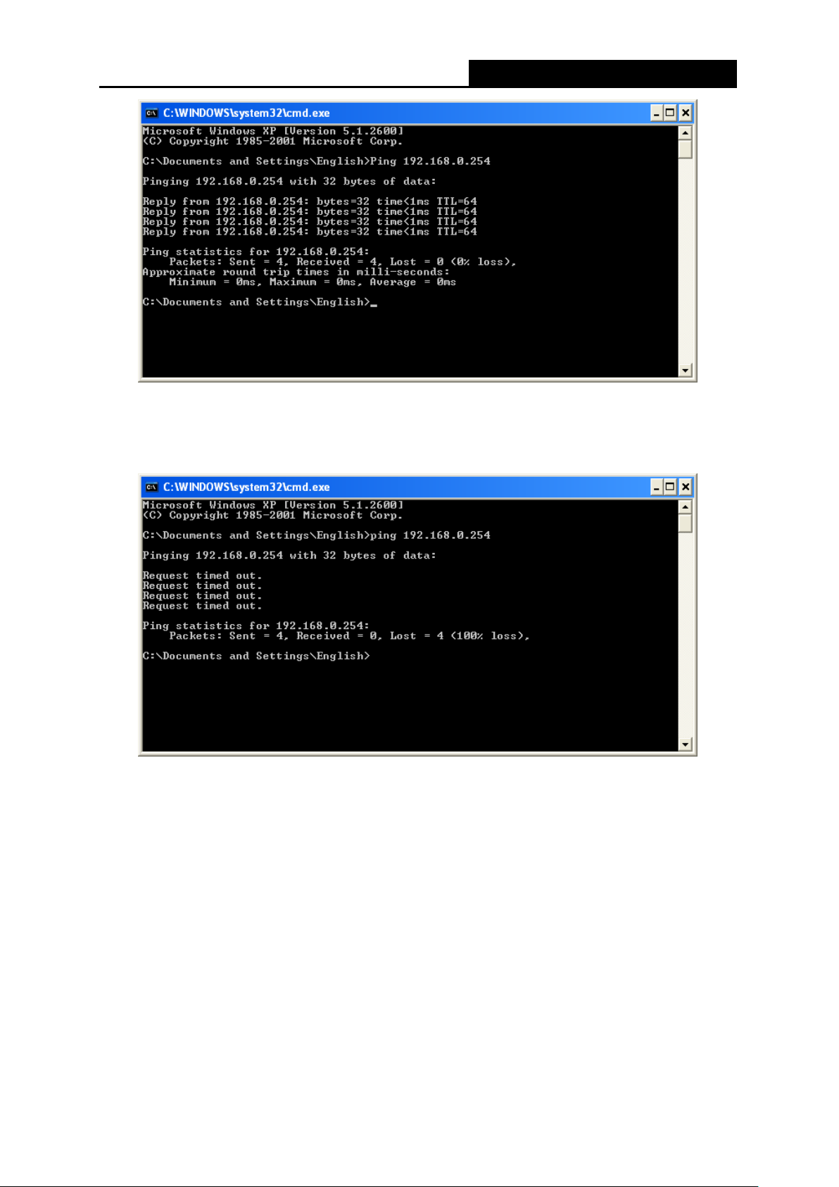
Now, you can run the Ping command in the command prompt to verify the network connection
between your PC and the Router. The following example is in Windows XP.
Open a command prompt, and type ping 192.168.0.254, and then press Enter.
If the result displayed is similar to the Figure 3-1, it means the connection between your PC
is the Password on the label.
and the Router has been established well.
- 11 -
Page 27
TL-WR80
2N
Mbps Wireless N Nano Router
300
igure 3-1 Success result of Ping command
F
I
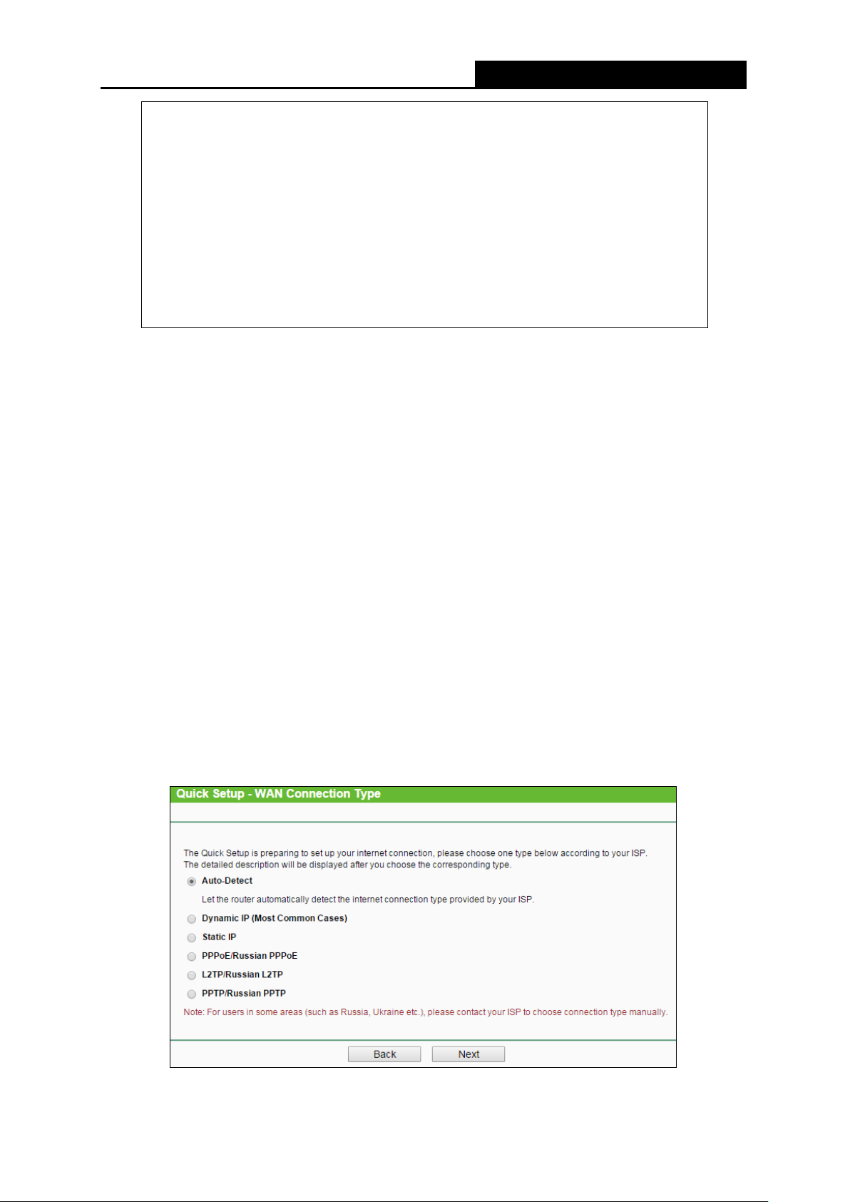
f the result displayed is similar to the Figure 3-2, it means the connection between your PC
and the Router has failed.
F
igure 3-2 Failure result of Ping command
lease check the connection following these steps:
P
1. Is the connection between your PC and the Router correct?
ote:
N
N
ote:
- 12 -
The LED of LAN/WAN ports which you link to on the Router shou ld be l it.
2. Is the TCP/IP configurat io n for your PC correct?
If the Router's IP address is 192.168.0.254, your PC's IP address must be within the range of
192.168.0.1 ~ 192.168. 0.253.
Page 28

TL-WR80
2N
Mbps Wireless N Nano Router
300
.2 Quick Installation Guide
3
ith a Web-based utility, it is easy to configure and manage the TL-WR802N 300M bps Wirel ess
W
N Nano Router. The Web-based utility can be used on any Windows, Macintosh or UNIX OS with
a Web browser, such as Microsoft Internet Explorer, Mozilla Firefox or Apple Safari.
1. To access the configuration utility, open a web-browser and type in the default address
http://tplinkwifi.net or http://tplinklogin.net in the addr ess field of the browser.
After a moment, a login window will appear, si milar to the Figure 3-3. Enter admin for the
User Name and Password, both in lower case letters. Then click the OK button or press the
Enter key.
F
igure 3-3 Login Windows
N
ote:
If the above screen does not pop-up, it means that your Web-br ow ser has b e en set t o a proxy. Go
to Tools menu>Internet Options>Connections>LAN Settings, in the screen that appears, cancel
the Using Proxy checkbox , and cli ck OK to finish it.
2. After a successful login, you can click the Quick Setup menu to quickly configure your
Router.
igure 3-4 Quick Setup
F
3. Cl
ick Next, and then Working Mode page will appear, shown in Figure 3-5.
- 13 -
Page 29
TL-WR80
2N
Mbps Wireless N Nano Router
300
igure 3-5 Quick Setup - Working Mode
F
N
ote:
The Router supports five working modes for multi-user to access the Internet: Standard Wireless
Router, Access Point, Repeater, Client and WISP Client Router. In Wireless Router mode,
the device enables multiple users to share the Internet connection via ADSL/Cable Modem. In
Access Point mode, this device can be connected to a wired network and transform the wired
access into wireless that multiple devices can share together. In Repeater mode, the device will
relay data to an associated root AP. In Client mode, the device will act as a wireless station to
enable wired host(s) to access AP. In WISP Client Router mode, the device enables multiple
users to share Internet connection from WISP. You can configure your device quickly by the
following steps in different modes.
3.2.1 Standard Wireless Router Mode
When you choose Standard Wireless Router on Working Mode page in Figure 3-5 , take the
following steps:
1. Click Next in
F
igure 3-6
.
F
igure 3-5
and then WAN Connection Type page will appear as shown in
,
F
igure 3-6 Quick Setup - WAN Connection Type
- 14 -
Page 30
TL-WR80
2N
Mbps Wireless N Nano Router
300
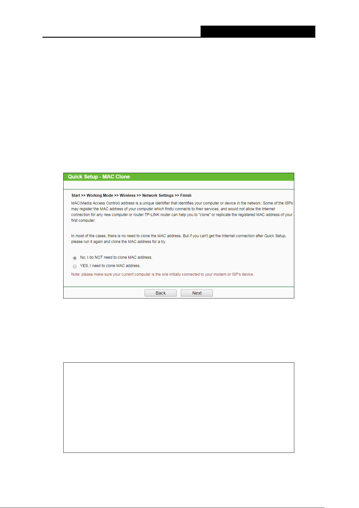
he Router supports five popular ways Dynamic IP, Static IP, PPPoE/Russian PPPoE,
T
L2TP/Russian L2TP and PPTP/Russian PPTP to connect to the Internet. To make sure the
connection type your ISP provides, please refer to the ISP. Make sure the cable is securely
plugged into the W A N port before detection.
Auto Detect - If you don't know the connection type your ISP provides, use this option to
allow the Quick Setup to search your Internet connection for servers and protocols and
determine your ISP config ur at ion.
Dynamic IP - Your ISP uses a DHCP service to assign your Router an IP address for
connecting to the Internet. When the Router connects to a DHCP server, or the ISP supplies
you with DHCP connection, please choose this type. If you choose this type of connection,
you can click Next and proceed to
F
igure 3-12
.
F
igure 3-7 Quick Setup - Static IP
Static IP - This type of connection uses a permanent, fixed (static) IP address that your ISP
assigned. In this type, you should fill in the IP address, Subnet Mask, Default Gateway, and
DNS IP address manually, which are specified by your ISP. Then click Next and proceed to
Figure 3-12.
igure 3-8 Quick Setup - Static IP
F
- 15 -
Page 31

TL-WR80
2N
Mbps Wireless N Nano Router
300
PPoE/Russian PPPoE - For this connection, you will need your account name and
P
password from your ISP.
If you have applied ADSL to realize Dial-up service, you should choose this type. Under this
condition, you should fill in both the User Name and Password that the ISP supplied. Please
note that these fields are case-sensitive.
F
igure 3-9 Quick Setup - PPPoE
L2
TP/Russian L2TP - For this connection, you will need your account name and password
from your ISP.
If you have applied ADSL to realize Dial-up service, you should choose this type. Under this
condition, you should fill in both the User Name and Password that the ISP supplied. Please
note that these fields are case-sensitive.
igure 3-10 Quick Setup – L2TP
F
P
PTP/Russian PPT P - For this connection, you will need your account name and password
from your ISP.
If you have applied ADSL to realize Dial-up service, you should choose this type. Under this
condition, you should fill in both the User Name and Password that the ISP supplied. Please
note that these fields are case-sensitive.
- 16 -
Page 32

TL-WR80
2N
Mbps Wireless N Nano Router
300
igure 3-11 Quick Setup - PPTP
F
2. Then, the Wireless page will appear as shown in
igure 3-12
F
. Set
the wireless parameters. It
is recommended that you rename an SSID, choose a Security Type and enter a Password.
Then click Next.
igure 3-12 Quick Setup - Wireless
F
Wireless Radio - Enable or disabl e t he wireless radio choosing from the pull-down list.
ireless Network Name - Enter a string of up to 32 characters. The same name of
W
SSID (Service Set Identification) must be assigned to all wireless devices in your
network. The default SSID is set to be TP-LINK_XXXX (XXXX indicates the last unique
four numbers of each Router’s MAC address). But it is recommended strongly that you
change your networks name (SSID) to a different value. T his value is case-sensitive.
For example, TEST is NOT the same as test.
- 17 -
Page 33

TL-WR80
2N
Mbps Wireless N Nano Router
300
ireless Security - You can configure the security settings o f y our wireless network.
W
•
D
isable Security - The wireless security function can be enabled or disabled. If
disabled, the wireless stations will be able to connect the Router w it hout encryption.
•
• N
A-PSK/WPA2-PSK - Input the password of your broadcast SSID.
WP
o Change - If you chose this option, wireless security configuration wi ll not change.
3. The Finish page is shown as Figure 3-13. Click the Reboot button to make your wireless
configuration ta ke effect and finish the Quick Setup.
F
igure 3-13 Quick Setup – Finish
2.2 Access Point Mode
3.
W
hen you choose Access Point on Working Mode page in Figure 3-5 , take the following steps:
1. Click Next in Figure 3-5, and then Wireless page will appear as shown in Figure 3-14.
Figure 3-14 Quick Setup - Wireless
- 18 -
Page 34

TL-WR80
2N
Mbps Wireless N Nano Router
300
ireless Network Name (SSID) - Enter a string of up to 32 characters. The same
W
name of SSID (Service Set Identification) must be assigned to all wireless devices in
your network. The default SSID is set to be TP-LINK_XXXX (XXXX indicates the last
unique four numbers of each Router’s MAC address). But it is recommended strongly
that you change your networks name (SSID) to a different value. This value is
case-sensitive. For example, TEST is NOT the same as test.
hannel - This field determines which operating frequency will be used. The default
C
channel is set to Auto. It is not necessary to change the wireless channel unless you
notice interference problems with another nearby access poi nt.
W
ireless Password - Input the password of your broadcast SSID.
2. Click the Next button. You can configure the IP parameters of LAN on this p age.
If you are not familiar with the setting items in this page, it's strongly recommended to keep
the provided default values, otherwise may result in low wireless n et work performance.
F
igure 3-15 Quick Setup – Network Settings
pe - Choosing SmartDHCP to get IP address from remoter DHCP server, or
Ty
choosing static IP to confi g I P addr ess manually.
IP
Address - Enter the IP address of your system in dotted-decimal notation (factory
default: 192.168.0.254).
S
ubnet Mask - An address code that determines the size of the network. Normally
255.255.255.0 is used as t he subnet mask.
- 19 -
Page 35

TL-WR80
2N
Mbps Wireless N Nano Router
300
3. C
lick the Next button. You will then see the Finish page.
F
igure 3-16 Quick Setup - Finish
3.2.3 Repeater Mode
hen you choose Repeater Mode on Working Mode page in Figure 3-5 , take the following
W
steps:
1. Click Next, and then Wireless Repeater page will appear as shown in Figure 3-17.
F
igure 3-17 Quick Setup - Wireless
W
ireless Name of Root AP - The SSID o f AP that you w ant to access.
AC Address of Root AP - The MAC address of AP that you want to access.
M
urvey - Click this button, you can search the AP which runs i n t he environment.
S
- 20 -
Page 36

TL-WR80
2N
Mbps Wireless N Nano Router
300
DS Mode - In WDS Repeater mode, the AP with WDS enabled will relay data to an
W
associated root AP. AP function is enabled meanwhile. The wireless repeater relays
signal between its stations and the root AP for greater wireless range. Please input the
MAC address of root AP i n t he fi el d "MAC Address of Root AP".
W
2. Click Survey button on the Wireless p age as sh own in Figure 3-17, and then AP List p age will
ireless Security Mode - This option should be chosen according to the security
configuration of the AP you want to access. It is recommended that the security type is
the same as your AP’s securit y type.
W
ireless Password - If the AP your router is going to connect need password, you
need to fill the password in t his bl ank.
appear as shown in Figure 3-18. Find the SSID of the Access Point you want to access, and
click Connect in the correspon ding r ow. For example, the second item is selected. The target
network’s SSID will be automatically filled into the corresponding box which is shown as the
Figure 3-17.
F
igure 3-18 AP List
N
ote:
If you know the SSID of the desir ed AP, you can also input it into the field "SSID" manually.
3. Click the Next button in Figure 3-17. Y ou will then s ee t he Finish page.
Because something has changed on the Wireless Repeater page, you will see the Finish
page as shown in Figure 3-19. Click the Reboot button to make your wireless configuration
take effect and finish the Quick Setup.
- 21 -
Page 37

TL-WR80
2N
Mbps Wireless N Nano Router
300
F
igure 3-19 Quick Setup - Finish
3.2.4 Client Mode
W
hen you choose Client on Working Mode page in Figure 3-5 , take the following steps:
1. Click Next in Figure 3-5, and then Wireless Client page will appear as shown in Figure 3-20.
F
igure 3-20 Quick Setup - Wireless
W
ireless Name of Root AP - Enter the SSID that you w ant to access.
AC Address of Root AP - Enter the MAC addre ss of AP that you want to access.
M
Su
rvey - Click this button, you can survey the AP which runs in the environment.
- 22 -
Page 38

TL-WR80
2N
Mbps Wireless N Nano Router
300
ireless Security Mode - This option should be chosen according to the security
W
configuration of the AP you want to access. It is recommended that the security type is
the same as your AP’s security type.
ireless Password - If the AP y our router is going to connect need pas sword, you need
W
to fill the password in this bla nk.
2. Click Survey button on the Wireless p age as sh own in Figure 3-20, and then AP L ist p a ge wi ll
appear as shown in Figure 3-21. Find the SSID of the Access Point you want to access, and
click Connect in the corresponding row. For example, t he second item is selected. The target
network’s SSID will be automatically filled into the corresponding box which is shown as the
Figure 3-20.
Figure 3-21 AP List
3. Click the Next button in Figure 3-22. You will then see the Finish page. Click the Reboot
button to make your wireless configuration take effe ct and f ini sh t he Quick Setup.
F
igure 3-22 Quick Setup - Finish
3.2.5 WISP Client Router Mode
hen you choose WISP Client Router Mode on Working Mode page in Figure 3-5 , take the
W
following steps:
1. Click Next, and then WAN Connection Type page will appear as shown in Figure 3-23.
- 23 -
Page 39

TL-WR80
2N
Mbps Wireless N Nano Router
300
F
igure 3-23 Quick Setup – WAN Connection Type
T
he Router supports five popular ways Dynamic IP, Static IP, PPPoE/Russian PPPoE,
L2TP/Russian L2TP and PPTP/Russian PPTP, to connect to the Internet. To make sure the
connection type your ISP provides, please refer to the ISP. Make sure the cable is securely
plugged into the W A N port before detection.
Dynamic IP - Your ISP uses a DHCP service to assign your Router an IP address for
connecting to the Internet. When the Router connects to a DHCP server, or the ISP
supplies you with DHCP connection, please choose this type. If you choose this type of
connection, no configuration should be set and you can go on with the wireless
igure 3-28
configuration in
S
tatic IP - This type of connection uses a permanent, fixed (static) IP address that your
F
.
ISP assigned. In this type, you should fill in the IP address, Subnet Mask, Default
Gateway, and DNS IP address manually, which are specified by your ISP. Then click
Next and proceed to Figure 3-28.
igure 3-24 Quick Setup - St atic IP
F
PPPoE/Russian PPP oE - For this connection, you will need your account name and
password from your ISP.
- 24 -
Page 40

TL-WR80
2N
Mbps Wireless N Nano Router
300
f you have applied ADSL to realize Dial-up service, you should choose this type. Under
I
this condition, you shoul d fill in both t h e User Na me and Password that the ISP supplied.
Please note that these fiel ds ar e case-sensitive.
F
igure 3-25 Quick Setup - PPPoE
L2TP/Russian L2TP - For this connection, you will need your account name and
password from your ISP.
If you have applied ADSL to realize Dial-up service, you should choose this type. Under
this condition, you shoul d fill in both t h e User Na me and Password that the ISP supplied.
Please note that these fiel ds ar e case-sensitive.
F
igure 3-26 Quick Setup – PPPoE
P
PTP/Russian PPTP - For this connection, you will need your account name and
password from your ISP.
If you have applied ADSL to realize Dial-up service, you should choose this type. Under
this condition, you shoul d fill in both t h e User Na me and Password that the ISP supplied.
Please note that these fiel ds ar e case-sensitive.
- 25 -
Page 41

TL-WR80
2N
Mbps Wireless N Nano Router
300
F
igure 3-27 Quick Setup - PPPoE
2. You can configure the basic settings for the w irel ess network on this page.
F
igure 3-28 Quick Setup - Static IP
S
SID - The SSID of the A P y our router is going to c onnect t o as a client. Y ou can also use
the search function to select the SSID to join.
BSSID - The BSSID of the AP your router is going to connect to as a cl ient . You can also
use the search function to select t he BSSID to join.
Su
K
rvey - Click this button, y ou can s urvey the AP which runs in the current channel.
ey ty pe - This option should be chosen according to the AP's security configuration. It
- 26 -
Page 42

TL-WR80
2N
Mbps Wireless N Nano Router
300
s recommended that the security type is the same as your AP's security type.
i
EP Index - This option should be chosen if the key type is WEP ( ASCII) or WEP (HEX) .
W
It indicates the index of th e WEP key.
A
uth type - This option should be chosen if the key type is WEP ( ASCII) or WEP (HEX) .It
indicates the authorizat ion type of the Root AP.
assword - If the AP y our rout er is go ing to co nnect needs pass w ord, y ou nee d to fi ll the
P
password in this blan k.
al SSID - Enter a value of up to 32 characters. The same N ame (SSID) mus t be
Loc
assigned to all wireless devices in your network.
Wireless Security Mode - You can configure the security settings of your wireless
network.
ireless Password - Input the password of your Local SSID.
W
3. Click Survey button on the Wireless p age as sh own in Figure 3-23, and then AP L ist p a ge wi ll
appear as shown in Figure 3-29. Find the SSID of the Access Point you want to access, and
click Connect in the corresponding row. For example, t he second item is selected. The target
network’s SSID will be automatically filled into the corresponding box which is shown as the
Figure 3-23. Then click Next.
F
igure 3-29 AP List
4. The Finish page is shown as Figure 3-30. Click the Reboot button to make your wire less
configuration ta ke effect and finish the Quick Setup.
igure 3-30 Quick Setup – Finish
F
- 27 -
Page 43

TL-WR80
2N
Mbps Wireless N Nano Router
300
ote:
N
The operating distance or range of your wireless connection varies significantly based on the
physical placement of the Rout er. For best results, place your Router.
Failure to follow these guidelines can result in significant performance degradation or inability to
wirelessly connect to the Router.
ear the center of the are a in which your wireless stations will oper at e.
N
n an elevated location such as a high shelf.
I
A
way from the potential sources of interfere nce, such as PCs, microwaves, and cordless
phones.
Away from large metal surfaces.
- 28 -
Page 44

TL-WR80
2N
Mbps Wireless N Nano Router
300
Ch
apter 4. Configuration for Wireless Router Mode
his chapter will show each Web page's key functions and the configuration way for Wireless
T
Router Mode of TL-WR802N.
.1 Login
4
A
fter your successful login, you can configure and manage the device. There are main menus on
the left of the web-based utility. Submenus will be available after y ou c lick o ne of the main menus.
On the right, there are the corr es ponding explanations and instructi ons.
F
igure 4-1
T
he detailed explan at ions for each Web page’s key function are listed below.
4
.2 Status
he Status page provides the current status information about the Router on Wireless Router
T
Mode. All information is read-only.
- 29 -
Page 45

TL-WR80
2N
Mbps Wireless N Nano Router
300
F
igure 4-2
F
irmware Version - The version in f or m at ion of the Router’s firmware.
H
ardware Version - The version infor m at ion of the Router’s hardware.
AN - This field displays the current settings or information for the LAN, you can configure
L
them in the Network > LAN page.
M
•
AC Address - The physical address of the Router, as seen from the LAN.
• I
P Address - The LAN IP address of the Router.
- 30 -
Page 46

TL-WR80
2N
Mbps Wireless N Nano Router
300
ubnet Mask - The subnet mask associated with LAN IP address.
S
•
ireless - This field displays basic information or status for wireless function, you can
W
configure them in the Wireless > Wireless Settings page.
rking Mode - The current wireless working mode in use.
•
Wo
ireless Radio - Indicates whether the wireless radio feature of the AP is enabled or
W
•
disabled.
ame (SSID) - The SSID of the Router.
•
N
ode - The current wireless mode which the Router works on.
•
M
hannel Width - The current wireless channel width in use.
•
C
hannel - The current wireless channel in use.
• C
MAC Address - The physical address of the Router, as seen from the WLAN.
•
W
•
DS Status - The status of WDS connection.
WAN - This field displays the current settings or information for the WAN, you can configure
them in the Network > WAN page.
•
MAC Address - The physica l address of the WAN por t , as s een from the Internet.
P Address - The current WAN (Internet) IP Ad dress. This fiel d will be blan k or 0.0. 0.0 if the
•
I
IP Address is assigned dynamically and there is no connection to the I nternet.
ubnet Mask - The subnet mas k ass ociated with the WAN IP Address .
•
S
efault Gateway - The Gateway currently used by the Router is shown here. When you
D
•
use Dynamic IP as the connection Internet type, the Renew button will be displayed here.
Click the Renew Button to obtain new IP parameters dynamically from the ISP. And if you
have got an IP address, Release button will be displayed here. Click the Release button to
release the IP address t he Router has obtained from the I SP.
DNS Server - The DNS (Domain Name System) server IP addresses currently used by the
Router.
Traffic Statistics - The Router’s traffic statistics.
eceived (Byt es) - Traffic that counted in by tes has been r eceiv ed out fro m the WAN port.
•
R
eceived (Packets) - Traffic that counted in packets has been received out from the WAN
•
R
port.
ent (Bytes) - Traffic that counted in bytes has been sent out from the WAN port.
• S
ent (Packet s) - Traffic that count ed in packets has been sent out from the WAN port.
S
•
ystem Up Time - The length of the time since the Router was last powered on or reset.
S
Click the Refresh but t on t o get the latest status and settings of the R out er.
- 31 -
Page 47

TL-WR80
2N
Mbps Wireless N Nano Router
300
.3 Quick Setup
4
lease refer to Section 3.2: "Quick Installation Guide."
P
.4 WPS
4
WPS (Wi-Fi Protected Setup) can help you to quickly and securely connect to a network. This
section will guide you to a dd a new w ireless d ev ice to an exi stin g netw or k quickly by function. The
WPS function is only available when the Operation Mode is set to Access Point. Select menu
“WPS”, you will see the next screen s how n in Figure 4-3.
F
igure 4-3 WPS
W
PS Status - To enable or disable the WPS function here.
urrent PIN - The current value of the device's PIN is displayed here. The default PI N of the
C
device can be found in the labe l or Us er G uide.
estore PIN - Restore the PIN of the device to its default.
R
G
en New PIN - Click this button, and then you can get a new random value for the device's
PIN. You can ensure the network security by generat ing a new PIN.
D
isable PIN of this Device - WPS external registrar of entering the device’s PIN c an be
disabled or enabled manually. If the device receives multiple failed attempts to authenticate
an external Registrar, this function will be d isabled automatically.
A
dd Device - You can add a new device to the existing network manually by clicking this
button.
To add a new device:
If the wireless adapter supports Wi-Fi Protected Setup (WPS), you can establish a wireless
connection between wireless adapter and device using either Push Button Configuration (PBC)
method or PIN method.
- 32 -
Page 48

TL-WR80
2N
Mbps Wireless N Nano Router
300
ote:
N
To build a successful connection by WPS, you should also do the corresponding configuration of
the new device for WPS function meanw hile.
For the configuration of the new device, here takes the Wireless Adapter of our company for
example.
I. By PBC
If the wireless adapter supports Wi-Fi Protected Setup and the Push Button Configuration (PBC)
method, you can add it to the net work by PBC with the following two methods.
Method One:
Step 1: Keep the WPS Status as Enabled and click the Add Device button in Figure 4-3, then
the following screen will a ppear.
F
igure 4-4 Add A New Dev ice
Step 2: Choose “Press the button of the new devi ce i n two minutes” and click Connect.
Step 3: For the configuration of the wireless adapter, please choose “Push the button on my
access point or wirele ss router” in the configuration utility of the WPS as below, and
click Connect.
he WPS Configuration Screen of Wireless Adapter
T
- 33 -
Page 49

TL-WR80
2N
Mbps Wireless N Nano Router
300
S
tep 4: Wait for a while until the next screen appears. Click OK to complete the WPS
configuration.
he WPS Configuration Screen of Wireless Adapter
T
Method Two: Enter the PIN into my AP.
Step 1: For the configuration of the wireless adapter, please choose “Enter the PIN of this
device into my access point or wireless router” in the configuration utility of the WPS
as below, and click Connect.
T
he WPS Configuration Screen of Wireless Adapter
N
ote:
In this example, the default PI N code o f t hi s adapter is 16952898 as the above figure shown.
Step 2: Keep the WPS Status as Enabled and click the Add Device button in Figure 4-3.
- 34 -
Page 50

TL-WR80
2N
Mbps Wireless N Nano Router
300
S
tep 3: Choose “Enter the new device's PIN” and enter the PIN code (take 16952898 for
example) of the wireless adapter in the field after PIN as shown in the figure below.
Then click Connect.
F
igure 4-5 Add A New Device
M
ethod Three : Ent er the PIN from my AP
Step 1: Get the Current PI N cod e of the AP in Figure 4-3 (each AP ha s it s un ique PI N c ode. H ere
takes the PIN code 12 345670 of this AP for example).
Step 2: For the configuration of the wireless adapter, please choose “Enter the PIN of my
access point or wireless router” in the configuration utility of the WPS as below, and
enter the PIN code of the AP into the field aft er “A ccess P oint PI N”. Then click Connect.
he WPS Configuration Screen of Wireless Adapter
T
ote:
N
The default PIN code of the AP can be found in its label or the WPS configuration screen as
Figure 4-3.
- 35 -
Page 51

TL-WR80
2N
Mbps Wireless N Nano Router
300
ou will see the following screen when the new dev ice has successful ly connect ed to the network.
Y
igure 4-6
F
ote:
N
1. The WPS LED on the AP will light green for five minutes if the device has been successfully
added to the network.
2. The WPS function cannot be configured if the Wireless function of the AP is disabled. Please
make sure the Wireless function is enabled before configuring t he WPS.
.5 Working Mode
4
T
he Router supports five operation mode types: Wireless Router, Access Point, Repeater,
Client and Wireless Client Router. Please select one you want. Click Save to save your choice,
which is shown as Figure 4-7.
F
igure 4-7 Wireless Working Mode Settings
S
tandard Wireless Router - The wireless Router Mode. In this mode, the device enables
multi-user to share Internet via DSL/Cable Modem. The only wired port works as WAN.
ccess Point - The w irel es s access point mode.
A
epeater - The wireles s Rep eat er M ode. It could extend the range of wireless network.
R
Client - The Client Mode. The computer connected by Ethernet could get access to an AP by
Client mode.
- 36 -
Page 52

TL-WR80
2N
Mbps Wireless N Nano Router
300
W
ISP Client Router - In this mode, the device enables multiple users to share Internet
connection from WISP.
.6 Network
4
F
igure 4-8 the Network menu
T
here are three submenus under the Network menu (shown in Figure 4-8): WAN, MAC Clone
and LAN. Click any of them, and you will be able to configure the corresponding functi on.
4.6.1 WAN
hoose menu “Network → WAN”, and then you can configure th e I P parameters of the WAN on
C
the screen below.
1. If your ISP provides the DHCP ser vice, please choose Dynamic IP type, and the Router will
automatically get IP parameter s fro m your ISP. You can see the page as follow (Figure 4-9):
igure 4-9
F
AN – Dynamic IP
W
- 37 -
Page 53

TL-WR80
2N
Mbps Wireless N Nano Router
300
his page displays the WAN IP parameters assigned dynamically by your ISP, including IP
T
address, Subnet Mask, Default Gateway, etc. Click the Renew button to renew the IP
parameters from your I SP. Click the Release butt on to release the IP param et er s.
MTU Size - The normal MTU (Maximum Transmission Unit) value for most Ethernet
networks is 1500 Bytes. It is not recommended that you change the default MTU Size
unless required by your I SP.
Use These DNS Servers - If your ISP gives you one or two DNS addresses, select Use
These DNS Servers and enter the primary and secondary addresses into the correct
fields. Otherwise, the DN S servers will be assigned dynamically from your ISP.
Note:
If you find error when you go to a website after entering the DNS addresses, it is likely that
your DNS servers are set up improperly. You should contact your ISP to get DNS server
addresses.
Host Name - This option s pecifies the Host Name of the Router.
Get IP with Unicast DHCP - A few ISPs' DHCP servers do not support the broadcast
applications. If you cannot get the IP Address normally, you can choose this option. (It is
rarely required.)
Click the Save button to save your settings.
2. If your ISP provides a static or fixed I P Address, Subnet Mask, Default Gateway and DNS
setting, select Static IP. The Static IP settings page w ill appear as shown in Figure 4-10.
igure 4-10
F
P Address - Enter the IP address in dotted-decimal notation provided by your ISP.
I
ubnet Mask - Enter the subnet Mask in dotted-decimal notation provided by your ISP,
S
W
AN - Static IP
usually is 255.255.255.0.
- 38 -
Page 54

TL-WR80
2N
Mbps Wireless N Nano Router
300
efault Gateway - Enter the gateway IP address in dotted-decimal notation provided by
D
your ISP.
M
TU Size - The normal MTU (Maximum Transmission Unit) value for most Ethernet
networks is 1500 Bytes. It is not recommended that you change the default MTU Size
unless required by your I SP.
P
rimary/Secondary DNS - (Optional) Enter one or two DNS addresses in
dotted-decimal not at ion provided by your ISP.
Click the Save button to save your settings.
3. If yo ur ISP provides a PPPoE connection, select PPPoE/Russia PPPoE option. Then you
should enter the following parameters (Figure 4-11):
F
igure 4-11
ser Name/Password - Enter the User Name and Password provided by your ISP.
U
AN – PPPoE/Russia PPPoE
W
These fields are case-sensitive.
onfirm Password - Enter again the Password provided by your ISP to ensure the
C
password you entered i s correct.
S
econdary Connection - It’s available only for PPPoE Connection. If your ISP provides
an extra Connection type such as Dynamic/Static IP to connect to a local area network,
then you can check the radio button of Dynamic/Static IP to activate this secondary
connection.
- 39 -
Page 55

TL-WR80
2N
Mbps Wireless N Nano Router
300
isabled - The Secondary Connection is disabled by default, so there is PPPoE
D
•
connection only. This is recommended.
ynamic IP - You can check this radio button to use Dynamic IP as the secondary
•
D
connection to connect to the local area network provided by ISP.
tatic IP - You can check this radio button to use Static IP as the secondary
•
S
connection to connect to t he loc al area network provided by ISP.
onnect on Demand - In this mode, the Internet connection can be terminated
C
automatically after a specified inactivity period (Max Idle Time) and be re-established
when you attempt to access the Internet again. If you want your Internet connection
keeps active all the time, please enter “0” in the Max Idle Time field.
therwise, enter
O
the number of minutes you want to have elapsed before your Internet access
disconnects.
onnect Automatically - The connection can be re-established automatically when it
C
was down.
me-based Connecting - The connection w ill only be es ta blished in t he period fro m the
Ti
start time to the end time (both are in HH:MM format).
Note:
Only when you have configured the system time on “System Tools → Time” page, will the
Time-based Connecting function can take effect.
onnect Manually - You can click the Connect/Disconnect button to
C
connect/disconnect im mediately. This mode also supports the Max Idle Time function as
Connect on Dema nd mode. The Internet connectio n can be disconnected automatically
after a specified inactivity period and re-established when you attempt to access the
Internet again.
Click t he Connect button to connect immediately. Click the Disconnect button to disconnect
immediately.
Caution: Sometimes the connection cannot be terminated although you specify a time to
Max Idle Time because some applications are visiting the Internet continually in the
background.
If you want to do some advanced configurations, please click the Advanced button, and the
page shown in Figure 4-12 will then appear:
- 40 -
Page 56

TL-WR80
2N
Mbps Wireless N Nano Router
300
igure 4-12 PPPoE Advanced Settings
F
M
TU Size - The default MTU size is “1480” bytes, which is usually fine. It is not
recommended that you change the default MTU Size unless required by your ISP.
S
ervice Name/AC Name - The service name and AC (Access Concentrator) name
I
should not be configured unless you are sure it is necessary for your ISP.
n most cases,
leaving these fields blank will work.
P Specified IP Address - If your ISP does not automatically assign IP addresses to
IS
the Router during login, please click “Use IP address specified by ISP” check box and
enter the IP address pr ovided by your ISP in dotted-decimal notation.
etect Online Interval - The Router will detect Access Concentrator online at every
D
interval. The def ault value is “0”. You can input the value between “0” and “120”. The
value “0” means no detect .
rimary DNS/Secondary DNS - If your ISP does not automatically assign DNS
P
addresses to the Router during login, please click “Use the following DNS servers”
check box and enter the IP address in dotted-decimal notation of your ISP’s primary
DNS server. If a secondary DNS server addres s i s available, enter it as we ll.
Click the Save button to save your settings.
4. If yo ur ISP provides BigPond Cable connection, please select BigPond Cable option. Then
you should enter the follow ing parameters (Figure 4-13):
- 41 -
Page 57

TL-WR80
2N
Mbps Wireless N Nano Router
300
Figure 4-13
ser Name/Password - Enter the User Name and Password provided by your ISP.
U
AN – BigPond Cable
W
These fields are case-sensitive.
uth Server - Enter the authenticating server IP address or host name.
A
A
uth Domain - Type in the domain suffix server name based on your location,
MTU Size - The default MTU size is “1480” bytes, which is usually fine. It is not
recommended that y ou change t he default MTU Size unless required by your ISP.
Connect on Demand - In this mode, the Internet connection can be terminated
automatically after a specified inactivity period (Max Idle Time) and be re-established
when you attempt to access the Internet again. If you want your Internet connection
keeps active all the time, please enter “0” in the Max Idle Time field.
O
therwise, enter
the number of minutes you want to have elapsed before your Internet access
disconnects.
onnect Automatically - The connection can be re-established automatically when it
C
was down.
onnect Manually - You can click the Connect/Disconnect button to
C
connect/disconnect im mediately. This mode also supports the Max Idle Time function as
Connect on Dema nd mode. The Inter net connect ion can be disconnected automatically
- 42 -
Page 58

TL-WR80
2N
Mbps Wireless N Nano Router
300
ter a specified inactivity period and re-established when you attempt to access the
af
Internet again.
Click t he Connect button to connect immediately. Click the Disconnect button to disconnect
immediately.
Caution: Sometimes the connection cannot be terminated although you specify a time to
Max Idle Time because some applications are visiting the Internet continually in the
background.
Click the Save button to save your settings.
5. If yo ur ISP provides L2TP connection, please select L2TP/Russia L2TP option. Then you
should enter the following par ameters (Figure 4-14):
igure 4-14
F
U
ser Name/Password - Enter the User Name and Password provided by your ISP.
W
AN – L2TP/Russia L2TP
These fields are case-sensitive.
D
ynamic IP/ Static IP - Choose either as you are given by your ISP. Click t he Connect
button to connect immediat ely. Click the Disconnect button to disconnect immediately.
- 43 -
Page 59

TL-WR80
2N
Mbps Wireless N Nano Router
300
C
onnect on Demand - You can configure the Router to disconnect from your Internet
connection after a specified period of inactivity (Max Idle Time). If your Internet
connection has been terminated due to inactivity, Connect on Demand enables the
Router to automatically re-establish your connection as soon as you attempt to access
the Internet again. If you wish to activate Connect on Demand, check the radio button.
If you want your Internet connection to remain active at all times, enter 0 in the Max Idle
Time field. Otherwise, enter the number of minutes you want to have elapsed before
your Internet connection terminates.
C
onnect Automatically - Connect automatically after the Router is disconne cted. To
use this option, check the r adio button.
C
onnect Manually - You can configure the Router to make it connect or disconnect
manually. After a specified period of inactivity (Max Idle Time), the Router will
disconnect from your Internet connection, and you will not be able to re-establish your
connection automatically as soon as you attempt to access the Internet again. To use
this option, check the radio button. If you want your Internet connection to remain active
at all times, enter "0" in the Max Idle Time field. Otherwise, ent er t he number of minutes
that you wish to have the Internet connecting last unless a new link is requested.
Caution: Sometimes the connection cannot be disconnected although you specify a time to
Max Idle Time, because some applications are visiting the Internet continually in the
background.
Click the Save button to save your settings.
6. If yo ur ISP provides PPTP connection, please select PPTP/Russia PPTP option. And you
should enter the following parameters (Figure 4-15):
- 44 -
Page 60

TL-WR80
2N
Mbps Wireless N Nano Router
300
igure 4-15 WAN – PPTP/Russ ia PPT P
F
ser Name/Password - Enter the User Name and Password provided by your ISP.
U
These fields are case-sensitive.
ynamic IP/ Static IP - Choose either as you are given by your ISP and enter the ISP’s
D
IP address or the do ma in name.
If you choose static IP and enter the domain name, you should also enter the DNS
assigned by your ISP. And click the Save button.
Click the Connect button to connect immediately. Click the Disconnect button to
disconnect immediately.
C
onnect on Demand - You can configure the Router to disconnect from your Internet
connection after a specified period of inactivity (Max Idle Time). If your Internet
connection has been terminated due to inactivity, Connect on Demand enables the
Router to automatically re-establish your connection as soon as you attempt to access
the Internet again. If you wish to activate Connect on Demand, check the radio button.
If you want your Internet connection to remain active at all times, enter “0” in the Max
- 45 -
Page 61

TL-WR80
2N
Mbps Wireless N Nano Router
300
le Time field. Otherwis e, enter the number o f minut es you want t o have elap sed before
Id
your Internet connection terminates.
onnect Automatically - Connect automatically after the Router is disconne cted. To
C
use this option, check the r adio button.
onnect Manually - You can configure the Router to make it connect or disconnect
C
manually. After a specified period of inactivity (Max Idle Time), the Router will
disconnect from your Internet connection, and you will not be able to re-establish your
connection automatically as soon as you attempt to access the Internet again. To use
this option, click the radio button. I f you w ant y our I nternet conn ectio n to r emain act ive a t
all times, enter "0" in the Max Idle Time field. Otherwise, enter the number in minutes
that you wish to have the Internet connecting last unless a new link is requested.
Caution: Sometimes the connection cannot be disconnected although you specify a time to
Max Idle Time because some applications are visiting the Internet continually in the
background.
Click the Save button to save your settings.
4.6.2 MAC Clone
C
hoose menu “Network → MAC Clone”, and then you can configure the WAN MAC address
on the screen below, as shown in Figure 4-16:
F
igure 4-16 MAC Address Clone
S
ome ISPs require that you register the MAC Address of your adapter. Changes are rarely
needed here.
W
AN M AC Addr ess - This field displays the current MAC address of the WAN port. If your
ISP requires you to register the MAC address, please enter the correct MAC address into
this field in XX-XX-XX-XX-XX-XX format (X is any hexadecimal digit).
our PC's MAC Address - This field displays the MAC address of the PC that is managing
Y
the Router. If the MAC address is required, you can click the Clone MAC Address To
button and this MAC addr ess will fill in the WAN MAC Address field.
Click Restore Factory MAC to restore the MAC address of WAN port to the factory default
value.
- 46 -
Page 62

TL-WR80
2N
Mbps Wireless N Nano Router
300
lick the Save button to save your settings.
C
N
ote:
1. Only the PC on your LAN can use the MAC Address Clone function.
2. If you change WAN MAC Address when the WAN connection is PPPoE, it will not take effect
until the connection is re-established.
4.6.3 LAN
hoose menu “Network → LAN”, and then you can configure the IP parameters of the LAN on
C
the screen as below.
igure 4-17 LAN
F
M
AC Ad dre ss - The physi cal add ress of the LAN ports, as seen from the LAN. The value
can't be changed.
P Address - Enter t he IP addres s of your Router in dotted-decimal notation (fact ory default:
I
192.168.0.1).
ubnet Mask - An address code that determines the size of the network. Normally use
S
255.255.255.0 as the subnet ma sk.
IGMP P ro x y - The Internet Group Management Protocol (IGMP) feature allows your devices
in LAN can watch TV.
N
ote:
1. If you change the IP Address of LAN, you must us e t he new I P Address to login to the Router.
2. If the new LAN IP Address you set is not in the same subnet with the previous one, the IP
Address pool in the DHCP server will be configured automatically,while the Virtual Server an d
DMZ Host w ill not take effect until they are re-configured.
- 47 -
Page 63

TL-WR80
2N
Mbps Wireless N Nano Router
300
.7 Wireless
4
igure 4-18 Wireless menu
F
T
here are five submenus under the Wireless menu (shown in Figure 4-18): Wireless Settings,
Wireless Security, Wireless MAC Filtering, Wireless Advanced and Wi reless S t atisti cs. Click
any of them, and you will be able to configure the corresponding function.
4.7.1 Wireless Settings
hoose menu “Wireless → Wireless Settings”, and then you can configure the basic settings
C
for the wireless networ k on t his page.
F
igure 4-19 Wireless Settings - Router
W
ireless Network Name - Enter a string of up to 32 characters. The same name of SSID
(Service Set Identification) must be assigned to all wireless devices in your network. The
default SSID is set to be TP-LINK_XXXX (XXXX indicates the last unique four numbers of
each Router’s MAC address). But it is recommended strongly that you change your
networks name (SSID) to a different value. This value is case-sensitive. For example, TEST
is NOT the same as test.
- 48 -
Page 64

TL-WR80
2N
Mbps Wireless N Nano Router
300
M
ode - Select the desired mode. The default setting is 11bgn mixed.
11b
•
•
g mixed - Select if you are using both 802.11b and 802.11g wirel ess clients.
gn mixed - Select if you are using a mix of 802.11b, 11g, an d 11n wireless clients.
11b
When 11bg mixed mode is selected, onl y 11bg mixed wireless stations can connect to the
Router. It is strongly recommended that you set the Mode to 11bgn mixed, and all of
802.11b/g/n wireless stations can connect to the Router.
ote:
N
If 1 1bg mixed mode is selected in the Mode field, the Channel Width selecting field will turn
grey and the value will become 20M, which is unable to be changed.
C
hannel Width - Select any channel width from the pull-down list. The default setting is
automatic, which can auto matically adjust the channel width for your clients.
C
hannel - This field determ ines which oper ating fr equency will be used. Th e default chann el
is set to Auto. It is not necessary to change the wireless channel unless you notice
interference problems w it h anot her nearby access point.
E
nable Wireless Rout er Radio - The wireless r adio of the Router can be enab led or dis abled
to allow wireless stations access. If enabled, the wireless stations will be able to access the
Router. Otherwise, wireless st at ions will not be able to access the Router.
nable SSID Broadcast - If you select the Enable SSID Broad cast checkbox, the wireless
E
router will broadcast its name (SSID) on the air.
nable WDS - You can se lect to ena ble WDS. With this fun ction, the Router ca n bridge tw o or
E
more WLANs. If this checkbox is selected, you will have to set the following parameters as
shown below. Make sure the following settings are correct.
igure 4-20 Wireless Settings – WDS Bridging
F
- 49 -
Page 65

TL-WR80
2N
Mbps Wireless N Nano Router
300
SID (to be bridged) - The SSID of the AP your Router is going to connect to as a client.
S
You can also use the search funct ion to select the SSID to join.
SSID (to be bridged) - The BSSID of the AP your Router is going to connect to as a client.
B
You can also use the search function to select the BSSID to join.
Su
rvey - Click this button, you can survey the AP which runs in the current channe l.
Se
curity Options - This option should be chosen according to the AP's security
configuration. It is recommended that the security type is the same as your AP's security
type.
W
EP Index - This option should be chosen if the key type is WEP (ASCII) or WEP (HEX). It
indicates the index of the WEP k ey.
A
uth Type - This option should be chosen if the key type is WEP (ASCII) or WEP (HEX). It
indicates the authorizat ion type of the Root AP.
P
assword - If the AP your Router is going to connect needs password, you need to fill the
password in this blank.
e sure to click the Save button to save your set t ings on t his page.
B
ote:
N
1. The operating distance or range of your wireless connection varies significantly based on the
physical placement of the Rout er. For best results, place your Router.
ear the center of the are a in which your wireless stations will oper at e.
N
n an elevated location such as a high shelf.
I
A
way from the potential sources of interfere nce, such as PCs, microwav es, and cordle ss
phones.
A
way from large metal surfaces.
2. Failure to follow these guidelines can result in significant performance degradation or inability
to wirelessly connect to the Router.
4.7.2 Wireless Security
hoose menu “Wireless → Wireless Security”, and then you can configure the security
C
settings of your wireless n etwork.
There are three wireless security modes supported by the Router: WPA/WPA2-Personal,
WPA/WPA2-Enterprise and WEP (Wired Equivalent Privacy).
- 50 -
Page 66

TL-WR80
2N
Mbps Wireless N Nano Router
300
F
igure 4-21 Wireless Security
D
isable Security - The wireless security functio n ca n be enab led or disable d. If disa bled, the
wireless stations will be able to connect the Router without encryption. But it’s strongly
recommended to choose one of the following modes to enable security.
WPA-PSK/WPA2-Personal - It’s the W PA/WPA2 authentication type based on pre-shared
passphrase.
ersion
•
V
default setting is Automatic, which can select
WPA2-PSK (Pre-shared key of WPA) automatically based on the wireless station's
capability and request.
E
•
ncryption
either Automatic, or TKIP or AES as Encryption.
ou can choose the version of the WPA-PSK security on the drop-down list. The
- y
W
PA-PSK (Pre-shared key of WPA) or
- W
hen WPA-PSK or WPA is set as the Authentication Type, you can select
- 51 -
Page 67

TL-WR80
2N
Mbps Wireless N Nano Router
300
ote:
N
If you check the WPA-PSK/WPA2-PSK radio button and choose TKIP encryption, you will
find a notice in red as shown in Figure 4-22.
WPA /WPA2-Enterprise - It’s based on Radius Server.
F
igure 4-22
ersion
•
V
default setting is Automatic, which can select
(WPA version 2) automat i cally based on the wireless station's capability and request.
En
•
cryption -
Radius Server IP - Enter the IP addr ess of the Radius server.
•
adius Port - Enter the por t t hat Radius server used.
•
R
R
•
adius Passwor d - Enter the password for the Radius server.
roup Key Update Period - Specify the group key update interval in seconds. The value
•
G
should be 30 or above. En t er 0 t o disable the update.
WEP - It is based on the IEEE 802.11 standard.
pe - you can choose the type for the WEP security on the pull-down list. The default
Ty
•
setting is Automatic, which can select
automatically based on the wireless station's capability and r equest.
EP Key Format
•
W
ou can choose the version of the WPA security from the pull-down list. The
- y
Y
ou can select Automatic, TKIP or AES.
hared Key
S
exadecimal and
-
H
SCII formats are provided here
A
W
PA (Wi-Fi Protected Access) or WPA2
r Open System
o
hentication type
aut
exadecimal
.
H
format stands for any combination of hexadecimal digits (0-9, a-f, A-F) in the specified
length. ASCII format stands for any combination of keyboard characters in the specified
length.
W
•
EP Key (Password) - Select which o f the f our keys will be used and enter the matching
WEP key that you create. Make sure these values are identical on all wireless stations in
your network.
ey Type
•
K
encryption. "Disabled" me ans t his WEP key entry is invalid.
ou can select the WEP key length (64-bit, or 128-bit, or 152-bit.) for
- Y
- 52 -
Page 68

TL-WR80
2N
Mbps Wireless N Nano Router
300
64-b
not promoted) or 5 ASCII c har act er s.
128-bit - You can enter 26 hexade cimal d ig its (any combi nation of 0-9, a-f, A-F, zero key is
not promoted) or 13 ASCII characters.
152-bit - You can enter 32 hexade cimal d ig its (any combi nation of 0-9, a-f, A-F, zero key is
not promoted) or 16 ASCII characters.
ote:
N
If you do not set the key, the wireless security function is still disabled even if you have selected
Shared Key as Authentication Type.
Be sure to click the Save button to save your settings on this page.
Y
it -
ou can enter 10 hexadecimal d igits (any combination of 0-9, a-f, A-F, zero key is
4.7.3 Wireless MAC Filtering
C
hoose menu “Wireless → Wireless MAC Filtering”, and then you can control the wireless
access by configuring the Wireless MAC Filtering function, as shown in Figure 4-23.
igure 4-23 Wireless MAC Filtering
F
T
o filter wireless users by MAC Address, clic k Enable. The default sett ing is Disable.
M
AC Address - The wireless station's MAC address that y ou w ant to access.
tatus - The status o f this entry, either Enabled or Disable.
S
D
escription - A simple description of the wireless station.
To Add a Wireless MAC A ddr ess filtering entry, click the Add New… button. The "A dd or Modify
Wireless MAC Address Filtering entry" page will appear, shown in Figure 4-24:
- 53 -
Page 69

TL-WR80
2N
Mbps Wireless N Nano Router
300
igure 4-24 Add or Modify Wireless MAC Address Filtering entry
F
dd or modify a MAC Address Filtering e ntry, follow these instructions:
To a
1. Enter the appropriate MAC Address into the MAC Add ress field. The format of the MAC
Address is XX-XX-XX-XX-XX-XX (X is any hexadecimal digit). For example:
00-0A-EB-B0-00-0B.
2. Give a simple description for the wireless station in the Description field. For example:
Wireless station A.
3. Select Enabled or Disabled for t his ent r y on the Status pull-down list.
4. Click the Save button to save this entry.
To modify or delete an existing entry:
1. Click the Modify in the entry you want to modify. If you want to delete the entry, click the
Delete.
2. Modify the information.
3. Click the Save button.
Click the Enable All button to make all entries enabled
Click the Disable All button to ma ke a ll entries disabled.
Click the Delete All button to delete all entries.
Click the Next button to go to the next page.
Click the Previous button to return to the previous p age.
For example: If you desire that the wireless station A with MAC address 00-0A-EB-B0-00-0B and
the wireless station B with MAC address 00-0A-EB-00-07-5F are able to access the Router, but all
the other wireless stations cannot access the Router, you can configure the Wireless MAC
Address Filtering list by following these steps:
1. Click the Enabled button to enable this function.
2. Select the radio button “Allow the stations specified by any enabled entries in the list to
access” for Filtering Rules.
3. Delete all or disable all entries if there are any entrie s alr eady.
- 54 -
Page 70

4. Cl
ick the
dd New...
A
but
ton.
TL-WR80
2N
Mbps Wireless N Nano Router
300
1) Enter the MAC address
00-0A-EB-B0-00-0B/00-0A-EB-00-07-5F
n the MAC Address field.
i
2) Enter wireless station A/B in the Description field.
3) Select Enabled in the Status pull-down list.
4) Click the Save button.
5) Click the Back button.
The filtering rules that con figur ed should be similar to the following list :
F
igure 4-25 Filtering Rules
4.7.4 Wireless Advanced
hoose menu “Wireless → Wireless Advanced”, and then you can configure the advanced
C
settings of your wireless n etwork.
igure 4-26 Wireless Advanced
F
T
ransmit Power - Here you can specify the transmit power of Router. You can select High,
Middle or Low which you w ould like. High is the default setting and is recommended.
B
eacon Interval - Enter a value between 20-1000 milliseconds for Beacon Interval here.
The beacons are the packets sent by the Router to synchronize a wireless network. Beacon
Interval value determines the time interval of the beacons. The default value is 100.
R
TS Threshold - Here you can specify the RTS (Request to Send) Threshold. If the packet
is larger than the specified RTS Threshold size, the Router will send RTS frames to a
- 55 -
Page 71

TL-WR80
2N
Mbps Wireless N Nano Router
300
ticular receiving station and negotiate the sending of a data frame. The default value is
par
2346.
Fr
agmentation Threshold - This value is the maximum size determining whether packets
will be fragmented. Setting the Fragmentation Threshold too low may result in poor network
performance because of excessive packets. 2346 is the default setting and is
recommended.
DTIM Interval - This value determines the inter val o f t he Deliver y Traffic I ndica tion Mes sag e
(DTIM). A DTIM field is a countdown field infor ming c lient s of t he next wind ow f or liste ning t o
broadcast and multicast messages. When the Router has buffered broadcast or multicast
messages for associate d clients , it se nds th e ne xt DTIM with a DTIM I nterv al v alue. You can
specify the value between 1-255 Beacon Intervals. The default value is 1, which indicates
the DTIM Interval is the same a s Beacon Interval.
E
nable WMM - WMM function can guarantee the packets with high-pr ior ity messages being
transmitted preferenti al ly. It is strongly recommended enabled.
nable Short GI - This function is recommended for it will increase the data capacity by
E
reducing the guard interv al time
Ena
If you are not familiar with the setting items in this page, it's strongly recommended to keep the
provided default values; ot her w ise it may result in lower wireless network performance.
ble AP Isolation - This function isolate all connected wireless stations so that wireless
stations cannot access each other through WLAN. This function will be disabled if
WDS/Bridge is enabled.
N
ote:
.
4.7.5 Wireless Statistics
C
hoose menu “Wireless → Wireless Statistics”, and then you can see the MAC Address,
Current S tatus, Received Packets and Sent Packets for each connect ed w ireless station.
igure 4-27 Wireless Statistics
F
AC Address - The connected wireless stat ion 's MAC address
M
- 56 -
Page 72

TL-WR80
2N
Mbps Wireless N Nano Router
300
urrent Status - The connected wireless station's running status, one of
C
STA-ASSOC / STA-JOINED / WPA / WPA-PSK / WPA2 / WPA2-PSK / AP-UP / AP-DOWN /
isconnected
D
R
eceived Packets - Packets received by the station
ent Packets - Pac kets s ent by the station.
S
C
onfigure - The button is used for loading the item to the Wireless MAC Filtering list.
llow - If the Wireless MAC Filtering function enable, allow the station to access.
•
A
D
•
eny - If the Wireless MAC Filtering function enable, deny the stat ion t o access.
You cannot change any of the values on this page. To update this page and to show the current
connected wireless stations, click on the Refresh button.
If the numbers of connected wirele ss stat ions go be y ond one page, cl ick the Next button to go to
the next page and click the Previous button to return the pr evious page.
ote:
N
This page will be refreshe d aut omatically every 5 seconds.
STA-AUTH /
4
.8 DHCP
F
igure 4-28 The DHCP menu
There are three submenus under the DHCP menu (shown in Figure 4-28), DHCP Settings,
DHCP Clients List and Address Reservation. Click any of them, and you will be able to
configure the corresponding function.
4.8.1 DHCP Settings
C
hoose menu “DHCP → DHCP Settings”, and then you can configure the DHCP Server on the page as shown in Figure 4-29. The Router is set up by default as a DHCP (Dynamic Host Configuration Protocol) server, which provides the TCP/IP configuration for all the PC(s) that are connected to the Router on the LAN.
- 57 -
Page 73

TL-WR80
2N
Mbps Wireless N Nano Router
300
igure 4-29 DHCP Settings
F
DH
CP Server - Enable or Disable the DHCP server. If you disable the Server, you must
have another DHCP server within your network or else you must configure the computer
manually.
Start IP Address - Specify an IP address for the DHCP Server to start with when assigning
IP addresses. 192.168.0.100 is the default start ad dr ess .
E
nd IP Address - Specify an IP addr es s for the DH CP Serv er to end w ith w hen assign ing I P
addresses. 192.168.0.199 is the default end address.
A
ddress Lease Time - The Address Lease Time is the amount of time a network user will
be allowed connection to the Router with their current dynamic IP Address. Enter the
amount of time in minutes and the user will be "leased" this dynamic IP Address. After the
time is up, the user will be automatically assigned a new dynamic IP address. The range of
the time is 1 ~ 2880 minutes. The default value is 120 minutes.
D
efault Gateway (Optional) - It i s suggested to input the IP address of the LAN port of the
Router. The default value is 192.168.0.1.
D
efault Domain (Optional) - Input t he doma in name of your network.
Primary DNS - (Optional) Input the DNS IP address provided by your ISP or consult your
ISP. Or consult your ISP.
Secondary DNS (Optional) - Input the IP address of another DNS server if your ISP
provides two DNS servers.
N
ote:
To use the DHCP server function of the Router, you must configure all computers on the LAN as
"Obtain an IP Address autom at ically".
- 58 -
Page 74

TL-WR80
2N
Mbps Wireless N Nano Router
300
4.8.2 DHCP Client List
hoose menu “DHCP → DHCP Client List”, and then you can view the information about the
C
clients attached to t he Rout er in the screen as shown in Figure 4-30.
igure 4-30 DHCP Client List
F
C
lient Name - The name of the DHCP client
M
AC Ad dress - The MAC address of the DHCP client
ssigned IP - The IP address that the Router has allocated to the DHCP cl ient
A
Lease Time - The t i me of the D HCP cl ient leas ed. After the dy na mic IP a ddre s s has e xpired,
a new dynamic IP address will be aut omatically assigned to the user.
You cannot change any of the values on this page. To update this page and to show the current
attached devices, click the Refresh button.
4.8.3 Address Reservation
C
hoose menu “DHCP → Address Reservation”, and then you can view and add a reserved
address for clients via the next screen (shown in Figure 4-31).When you specify a reserved IP
address for a PC on the LAN, that PC will always receive the same IP address each time when it
accesses the DHCP server. Reserved IP addresses should be assigned to the servers that
require permanent IP settings.
F
igure 4-31 Address Reservation
AC Address - The MAC address of the PC for which you want t o r eser ve an IP address.
M
R
eserved IP Address - The IP address reserved for the PC by the Router.
tatus - The status of this entry, either Enabled or Disabled.
S
- 59 -
Page 75

TL-WR80
2N
Mbps Wireless N Nano Router
300
odify - To modify or delete an existing entr y.
M
To Reserve an IP address:
1. Click the Add New… button. Then will pop-up.
2. Enter the MAC address (in XX-XX-XX-XX-XX-XX format.) and IP address (in dotted-decimal
notation) of the co mputer for which you want to reserve an IP address.
3. Click the Save button.
igure 4-32 Add or Modify an Address Reserva tio n En try
F
To m
odify or delet e a n existing entry:
1. Click the Modify in the entry you want to modify. If you want to delete the entry, click the
Delete.
2. Modify the information.
3. Click the Save button.
Click the Enable/Disable All button to make all entries enabled/disabled.
Click the Delete All button to delete all entries.
Click the Next button to go to the next page and Click the Previous button to return t he pr evious
page.
4
.9 Forwarding
F
igure 4-33 The Forwarding menu
There are four submenus under the Forwarding menu (shown in Figure 4-33): Virtual Servers,
Port Triggering, DMZ and UPnP. Click any of them, and you will be able to configure the
corresponding function.
- 60 -
Page 76

TL-WR80
2N
Mbps Wireless N Nano Router
300
4.9.1 Virtual Servers
hoose menu “Forwarding → Virtual Servers”, and then you can view and add virtual servers
C
in the screen as shown in Figure 4-34. Virtual servers can be used for setting up public services
on your LAN, such as DNS, Email and FTP. A virtual server is defined as a service port, and all
requests from the Internet to this service port will be redirected to the computer specified by the
server IP. Any PC that was used for a virtual server must have a static or reserved IP Address
because its IP Address may be changed when u si ng the DHCP function.
igure 4-34
F
V
irtual Servers
Service Port - The numbers of External Ports. You can type a service port or a range of
service ports (in XXX – YYY format, XXX is the start port number, YYY is the end port
number).
I
nternal Port - The Internal Service Port number of the PC running the service application.
You can leave it blank if the Internal Port is the same as the Service Port, or enter a
specific port number when Service Port is a single one.
P Address - The I P Address of the PC providing the service application.
I
Pr
otocol - The protocol used for this application, either TCP, UDP, or All (all protocols
supported by the Router).
S
tatus - The status of this entry, either Enabled or Disabled.
odify - To modify or delete an existing entry.
M
To setup a virtual server entr y:
1. Click the Add New… button, the next screen w il l pop-up as shown in Figure 4-35.
2. Select the service port you w ant t o use from the Common Service Port list. If the Common
Service Port list does not have the service that you want to use, type the service port
number or service port range i n the Service Port box.
3. Type the IP Address of the computer in the IP A ddress box.
4. Select the protocol used for this applicat i on, eit her TCP, UDP, or All.
5. Select the Enabled to enable the virtual server.
6. Click the Save button.
- 61 -
Page 77

TL-WR80
2N
Mbps Wireless N Nano Router
300
igure 4-35 Add or Modify a Virtual Server Entry
F
ote:
N
If your computer or server has more than one type of available service, please select another
service, and enter the same IP Address for that computer or server.
To modify or de l e t e an existing entry:
1. Click the Modify in the entry you want to modify. If you want to delete the entry, click the
Delete.
2. Modify the information.
3. Click the Save button.
Click the Enable/Disable All button to make all entries enabled/disabled.
Click the Delete All button to delete all entries.
Click t he Next button to go to the next page and click the Previous button to return the previous
page.
ote:
N
If you set the service port of the virtual server as 80, you must set the Web management port on
“Security → Remote Management” page to be any other value except 80 such as 8080.
Otherwise there will be a conflict to disable the virtual server.
4.9.2 Port Triggering
C
hoose menu “Forwarding → Port Triggering”, and then you can view and add port triggering
in the screen as shown in Figure 4-36. Some applications require multiple connections, like
Internet games, video conferencing, Internet calling and so on. These applications cannot work
with a pure NAT Router. Port Triggering is used for some of these applications that can work with
an NAT Router.
- 62 -
Page 78

TL-WR80
2N
Mbps Wireless N Nano Router
300
igure 4-36
F
Port Triggeri ng
Once the Router is configured, the operation is as follows:
1. A local host makes an outgoing connection using a destination port number defined in the
Trigger Port fi eld.
2. The Router records this connection, opens the incoming port or ports associated with this
entry in the Port Triggering table, and associates them with the local host.
3. When necessary, the external host will be able to conne ct to the local host us ing one of the
ports defined in the Incoming Ports field.
rigger Port - The port for outgoing tr af f ic. An outgoing connect ion us ing th is por t will trigger
T
this rule.
rigger Protocol - The protocol used for Trigger Ports, either TCP, UDP, or All (all
T
protocols supported by the Router).
ncoming Port s - The port or port range used by the remote s yst em w hen it r espon ds to t he
I
outgoing request. A response using one of these ports will be forwarded to the PC that
triggered this rule. You can input at most 5 groups of ports (or port sections). Every group of
ports must be set ap ar t w ith ",". For example, 2000-2038, 2050-2051, 2085, 3010-3030.
I
ncoming Protocol - The protocol used for Incoming Ports Range, either TCP or UDP, or
ALL (all protocols supported by the Router).
Status - The status of this entry, either Enabled or Disabled.
Modify - To modify or delete an existin g ent r y.
To add a new rule, f ol l ow the steps below:
1. Click the Add New… button, the next screen w il l pop-up as show n in Figure 4-37.
2. Select a common application from the Common Applications drop-down list, then the
Trigger Port field and the Incoming Ports field will be automatically filled. If the Common
Applications do not have the application you need, enter the Trigger Port and the
Incoming Ports manually.
3. Select the protocol used for Trigger Port from the Trigger Protocol drop-down list, either
TCP, UDP, or All.
4. Select the protocol used for Incoming Ports from the Incoming Protocol drop-down list,
either TCP or UDP, or All.
- 63 -
Page 79

TL-WR80
5. S
elect Enabled in Status field.
6. Click the Save button to save the new rule.
F
igure 4-37 Add or Modify a Port Triggering Entr y
o modify or dele t e a n existing entry:
T
2N
Mbps Wireless N Nano Router
300
1. Click the Modify in the entry you want to modify. If you want to delete the entry, click the
Delete.
2. Modify the information.
3. Click the Save button.
Click the Enable All button to make al l entr i es enabled.
Click the Disable All button to ma ke all e nt r ies disabled.
Click the Delete All button to delete all entries.
N
ote:
1. When the trigger connection is released, t he corresponding opening port s will be closed.
2. Each rule is allowed to be used only by one host on LAN synchronously. The trigger
3. Incoming Port Range cannot overlap each other.
connection of other host s on LAN will be refused.
4.9.3 DMZ
C
hoose menu “Forwarding → DMZ”, and then you can view and configure DMZ host in the
screen as shown in Figure 4-38. The DMZ host feature allows one local host to be exposed to t he
Internet for a special-purpose service such as Internet gaming or videoconferencing. DMZ host
forwards all the ports at the same time. Any PC whose port is being forwarded must have its
DHCP client funct ion d isabled and should have a new static I P Address assigned to it bec ause it s
IP Address may be changed when using the DHCP functio n.
- 64 -
Page 80

TL-WR80
2N
Mbps Wireless N Nano Router
300
F
igure 4-38 DMZ
T
o assign a computer or server to be a DMZ server:
1. Check the Enable radio b ut ton.
2. Enter the IP Address of a local host in the DMZ Host IP Addres s field.
3. Click the Save button.
Note:
After you set the DMZ hos t , t he firew al l related to the host will not work.
4.9.4 UPnP
C
hoose menu “Forwarding → UPnP”, and then you can view the information about UPnP
(Universal Plug and Play) in the screen as shown in Figure 4-39. The UPnP feature allows the
devices, such as Internet computers, to access the local host resources or devices as needed.
UPnP devices can be automatically discovered by the UPnP service application on the LA N.
igure 4-39 UPnP
F
urrent UPnP Status - UPnP can be enabled or dis abled by cl ickin g the Enable or Disable
C
button.
Current UPnP Settings List - This table displays the current UPnP information.
• A
pp Description - The description provided by the application in the UPnP request.
xternal Port - The external port the Router opens for the ap plication.
•
E
• Pr
otocol - The type of protocol t he Router opens for the application.
•
Internal Port - The Internal port the Router opens for local host.
• I
P Address - The IP address of the UPnP device that is currently accessing the Router.
- 65 -
Page 81

TL-WR80
2N
Mbps Wireless N Nano Router
300
tatus - The status of the port is displayed here. “Enabled” means that the port is still
S
•
active. Otherwise, the port is inactive.
Click Refresh to update the Current UPnP Settings List.
.10 Security
4
igure 4-40 The Security menu
F
here are four submenus under the Security menu as shown in Figure 4-40: Basic Security,
T
Advanced Security , Local Management and Remote Ma nageme nt. Click any of them, and you
will be able to configure the corr es ponding function.
4.10.1 Basic Security
C
hoose menu “Security → B asic Security”, you can configure the basic security in the screen as shown in Figure 4-41.
igure 4-41 Basic Securit y
F
- 66 -
Page 82

TL-WR80
2N
Mbps Wireless N Nano Router
300
irewall - A fi rewall protects your network from the outside world. Here you can enable or
F
disable the Router’s firewall.
S
PI Firewall - SPI (Stateful Packet Inspection, also known as dynamic packet filtering)
helps to prevent cyber attacks by tracking more state per session. It validates that the
traffic passing through the session conforms to the protocol. SPI Firewall is enabled by
factory default. If you want all the computers on the LAN exposed to the outside world,
you can disable it.
V
PN - VPN Passthrough must be enabled if you want to allow VPN tunnels using IPSec,
PPTP, or L2TP protocols to pass through the Router’s firewall.
PTP Passthrough - Point-to-Point Tunneling Prot ocol (PPTP) al lows the Point-to-Point
P
Protocol (PPP) to be tunneled through an IP network. To allow PPTP tunnels to pass
through the Router, keep the default, Enable.
2TP Passthrough - Layer 2 Tunneling Protocol (L2TP) is the method used to enable
L
Point-to-Point sessions via the Internet on the Layer 2 level. To allow L2TP tunnels to
pass through the Router, k eep t he default, Enable.
IP
Sec Passthrough - Internet Protocol Security (IPSec) is a suite of protocols for
ensuring private, secure communications over Internet Protocol (IP) networks, through
the use of cryptographic security services. To allow IPSec tunnels to pass through the
Router, keep the default, Enable.
LG - It is recommended to enable Application Layer Gateway (ALG) because ALG allows
A
customized Network Address Translation (NAT) traversal filters to be plugged into the
gateway to support address and port translation for certain application layer "control/data"
protocols such as FTP, TFTP, H323 etc.
FT
P ALG - To allow FTP clients and servers to transfer data across NAT, keep the
default Enable.
TF
TP ALG - To allow TFTP clients and servers to transfer data across NAT, keep the
default Enable.
H
323 ALG - To allow Microsoft NetMeeting clients to communicate across NAT, keep
the default Enable.
Click the Save button to save your settings.
4.10.2 Advanced Security
hoose menu “Security → Advanced Security”, you can protect the Router from being
C
attacked by TCP-SYN Flo od, UDP Flood and ICMP-Flood in the screen as shown in Figure 4-42.
- 67 -
Page 83

TL-WR80
2N
Mbps Wireless N Nano Router
300
igure 4-42 Advanced Security
F
Packets Statistics Interval (5~60) - The default value is 10. Select a value between 5 and
60 seconds from the drop-down list. The Packets Statistics Interval value indicates the time
section of the packets st ati stics. The resu lt of the stat istics is used for analysis by SYN Flood,
UDP Flood and ICMP-Flood.
DoS Protection - Denial of Service protection. Check the Enable or Disable button to
enable or disable the Do S protect ion functi on. Only when it is ena bled, will t he flood fi lters be
enabled.
N
ote:
Dos Protection will take effect only when the Traffic Statistics in “System Tool → Traffic
Statistics” is enabled.
Enable ICMP-FLOOD Attack Filtering - Enable or Disable the ICMP-FLOOD Attack
Filtering.
ICMP-FLOOD Packets Threshold (5~3600) - The default value is 50. Enter a value
between 5 ~ 3600. When t he curr ent I CMP-FLOOD Packets number is bey on d the set value,
the Router will start up t he blocking function immediately.
Enable UD P-FLOOD Filtering - Enable or Disa bl e the UDP-FLOOD Filtering.
UDP-FLOOD Packets Threshold (5~3600) - The default value is 500. Enter a value
between 5 ~ 3600. When the current UPD-FLOOD Packets number is beyond the set value,
the Router will startup the blocking function immediately.
- 68 -
Page 84

TL-WR80
2N
Mbps Wireless N Nano Router
300
nable TCP-SYN-FLOOD Attack Filtering - Enable or Disable the TCP-SYN-FLOOD
E
Attack Filtering.
TCP-SYN-FLOOD Packets Threshold (5~3600) - The default value is 50. Enter a value
between 5 ~ 3600. When the current TCP-SYN-FLOOD Packets numbers is beyond the set
value, the Router will startup the blocking function immediately.
Ignore Ping Packet From WAN Port - Enable or Disable Ignore Ping Packet From WAN
Port. The default setting is disabled. If enabled, the ping packet from the Internet cannot
access the Router.
For bid Pi ng Pa ck et Fro m LAN Port - Enable or Disable Forbid Pin g Packet From LAN Port.
The default setting is disabled. If enabled, the ping packet from LAN cannot access the
Router. This function can be used to defend against some viruses.
Click the Save button to save the settings.
Click the Blocked DoS Host List button to display the DoS host table by bl ocking.
4.10.3 Local Management
hoose menu “Security → Local Management”, you can configure the managem ent r ul e in the
C
screen as shown in Figure 4-43. The management feature allows you to deny computers in LAN
from accessing the Router.
igure 4-43 Local Management
F
y default, the radio button “All the PCs on the LAN are allowed to access the Router's
B
Web-Based Utility” is checked. If you want to allow PCs with specific MAC Addresses to access
the Setup page of the Router's Web-Based Utility locally from inside the network, check the radio
button “Only the PCs listed can browse the built-in web pages to perform Administrator
tasks”, and then enter each MAC Address in a separat e fie ld. The f ormat for the MAC Address is
XX-XX-XX-XX-XX-XX (X is any hexadecimal digit). Only the PCs with MAC address l isted can
- 69 -
Page 85

TL-WR80
2N
Mbps Wireless N Nano Router
300
e the password to browse the built-in web pages to perform Administrator tasks while all the
us
others will be blocked.
After click the Add button, your PC's MAC Address will be place d in the list above.
Click the Save button to save your settings.
ote:
N
If your PC is blocked but you want to access the Router again, press and hold the WPS button
for more than 5 seconds to reset the Router to factor y defaults.
4.10.4 Remote Management
Y
ou can configure the Remote Management function on this page. This feature allows you to
manage your Router fro m a r em ot e location, via the Internet.
F
igure 4-44 Remote Management
W
eb Management Port - Web browser access normally uses the standard HTTP service
port 80. This router’s default remote management Web port number is 80. For greater
security, you can change the remote management Web interface to a custom port by
entering that number in this box provided. Choose a number between 1024 and 65535, but
do not use the number of any com m on ser vice port.
emote Management IP Address - This is the current address you will use when
R
accessing your router from the Internet. The default IP Address is 0.0.0.0. It means this
function is disabled. To enable this function, change the default IP Address to another IP
Address as desired.
To access the rout er, you will type y our rout er' s W A N IP Address into your bro wser 's Address (in
IE) or Location (in Nav igator) box, followed by a colon and the custom port number. For example,
if your Router's WAN address is 202.96.12.8 and you use port number 8080, enter in your
browser: http://202.96.12.8:8080. You will be asked for the r outer's password. After succes sf u lly
entering the password, you will be able to access the router's Web-based utility.
N
ote:
Be sure to change the rout er's default password to a very secure password.
- 70 -
Page 86

TL-WR80
2N
Mbps Wireless N Nano Router
300
.11 Parental Control
4
Cho
ose menu “Parental Control”, and you can configure the parental control in the screen as
shown in Figure 4-45. The Parental Control function can be used to control the internet activities
of the child, limit the child to acces s certain websites and restrict t he t ime of surfing.
F
igure 4-45
Parental Control - Check Enable if you want this function to take effect, otherwise check
Disable.
AC Address of Parental PC - In this field, enter the MAC address o f the controlling PC, or
M
you can make use of the Copy To Above button below.
AC Address of Your PC - This field displays the MAC address of the PC that is managing
M
this Router. If the MAC Address of your adapter is registered, you can click the Copy To
Above button to fill this addr ess t o t he M AC Address of Parental PC field above.
To add a new entry, please f ol l ow the steps below.
ebsite Description - Description of the allow ed website for the PC controlled.
W
Sc
hedule - The time period allowed for the PC controlled to acc ess the Internet. For detailed
information, please go to “Access Control→ Schedule”.
M
odify - Here you can edit or delete an exist ing entry.
arental Control Settings
P
1. Click the Add New… button and the next screen w ill pop-up as shown in Figure 4-46.
2. Enter the MAC address of the PC (e.g. 00-11-22-33-44-AA) you’d like to control in the MAC
Address of Child PC field. Or you can choose the MAC address from the All Address in
Current LAN drop-down list.
3. Give a description (e.g. Allow Google) for the website allowed to be accessed in the Website
Description field.
- 71 -
Page 87

TL-WR80
2N
Mbps Wireless N Nano Router
300
nter the allowed domain name of the website, either the full name or the keywords (e.g.
4. E
google) in the Allowed Domain Name field. Any domain name with keywords in it (e.g.
www.google.com
elect fr om the E ffective T ime drop-down list the schedule (e.g. Schedule_1) you want the
5. S
entry to take effec t. If there are not suitable schedules for you, click the Schedule i n red
below to go to the Advance Sch edule Settings page and create the schedule you need.
6. In the Status field, you can select Enabled or Disabled to enable or disable your entry.
7. Click the Save button.
Click the Enable All button to enable all the rules in t he list.
Click the Disable All button to disable all the rules in the list.
Click the Delete All but ton to delete all the entries in the table.
Click the Next button to go to the next page, or click the Previous button return to the previous
page.
will be allowed.
)
F
igure 4-46
For
example: If you desire that the child PC with MAC address 00-11-22-33-44-AA can access
A
dd or Modify Parental Control Entry
www.google.com on Saturday only while the parent PC with MAC address 00-11-22-33-44-BB is
without any restriction, you should follow the settings below.
1. Click “Parental Control” menu on the left to enter the Parental Control Settings page. Check
Enable and enter the MAC address 00-11-22-33-44-BB in the MAC Address of Parental PC
field.
- 72 -
Page 88

TL-WR80
2N
Mbps Wireless N Nano Router
300
2. Cl
3. Click “Parental Control” m enu on the left to go back to the Add or Modify Parental Control
4. Click Save to complete the settings.
Then you will go bac k to t he Par enta l Contr ol Sett ings pa ge and s ee th e fol low ing list , as show n in
ick “Access Restriction → Schedule” on the left to enter the Schedule Settings page.
Click Add New... button to create a new schedule with Schedule Description is Schedule_1,
Day is Sat and Time is all day-24 hour s .
Entry page:
Cl
ick Add New... button.
nter 00-11-22-33-44-AA in the MAC Address of Child PC field.
E
E
nter “Allow Google” in the Website Description field.
E
nter “www.google.com” in the Allowed Domain Nam e field.
elect “Schedule_1” you create just now from the Effective Time drop-down list.
S
In Status field, select Enable.
Figure 4-47.
igure 4-47
F
4
.12 Access Control
igure 4-48 The Access Control menu
F
T
here are four submenus under the Access Restriction menu as shown in Figure 4-48: Rule,
Host, Target and Schedule. Click any of them, and you will be able to configure the
corresponding function.
4.12.1 Rule
Cho
ose menu “Access Control→ Rule”, you can view and set Access Restriction rules in the
screen as shown in Figure 4-49.
- 73 -
Page 89

TL-WR80
2N
Mbps Wireless N Nano Router
300
F
igure 4-49 Access Control Rule Management
E
nable Internet Access Control - Select the check box to enable the Internet Access
Restriction function, so the Default Filter Policy can take effect.
R
ule Name - Here displays the name of the rule and this name is uniqu e.
ost - Here displays the host selected in the corresponding rule.
H
T
arget - Here displays the target selected in the corresponding ru le.
Schedule - Her e dis plays the schedule selected in the corresponding rule.
A
ction - Here displays the action the Router takes t o deal with t he packets. It could be Allow
or Deny. Allow means that the Router permits the packets to go through the Router. Deny
means that the Router rej ect s t he packets to go through the Router.
S
tatus - This field displays the status of the rule. Enabled means the rule will take effect,
Disabled means the rule will not take effect.
M
odify - Here you can edit or delete an exist ing rule.
To add a new rule, pl e ase follow the steps below.
1. Click the Add New… but t on and t he next screen will pop-up as shown in Figure 4-50.
2. Give a name (e.g. Rule_1) for t he rule i n t he Rule Name field.
3. Select a host from the Host drop-down list or choose “Click Here To Add New Host List”.
4. Select a target from the Target drop-sown list or choose “Click Here To Add New Target
List”.
5. Select a schedule from the Schedule drop-down list or choose “Click Here To Add New
Schedule”.
- 74 -
Page 90

TL-WR80
2N
Mbps Wireless N Nano Router
300
6. I
n the Action field, select Deny or Allow.
7. In the Status field, select Enabled or Disabled to enable or disable your entr y.
8. Click the Save button.
Click the Enable All button to enable all the rules in t he list.
Click the Disable All button to disable all the rules in the list.
Click the Delete All but ton to delete all the entries in the table.
You can change the entry’s order as desired. Fore entries are before hind entries. Enter the ID
number in the first box you want to move and another ID number in seco nd box y ou w ant to move
to, and then click the Move button to change the entry’s order.
Click the Next button to go to the next page, or click the Previous button return to the previous
page.
F
igure 4-50 Add or Modify Internet Access Restriction Entry
For
example: If you desire to allow the host with MAC address 00-11-22-33-44-AA to access
www.google.com o nly f rom 18:00 to 20:00 on Saturday and Sunday, and forbid other hosts in
the LAN to access the Internet, you should follow the settings below:
1. Click “Access Control → Host” in the left to enter the Host Settings page. Add a new entry
with the Host Description is Host _1 and MAC Address is 00-11-22-33-44-AA.
2. Click “Access Control → Target” in the left to enter the Target Settings page. Add a new
entry with the Target Desc r iption is Target_1 and Domain Name is ww w . google.com.
3. Click “Access Control → Schedule” in the left to enter the Schedule Settings page. Add a
new entry with the Schedule Description is Schedule_1, Day is Sat and Sun, Start Time is
1800 and Stop Time is 2000.
4. Click “Access Control → Rule” in the left to return to the Access Restriction Rule
Management page. Select “Enable Internet Access Restriction” and choose "Deny the
packets not specified by any access Restriction policy to pass through the Rout er".
5. Click Add New... button to add a new rule as follows:
- 75 -
Page 91

TL-WR80
2N
Mbps Wireless N Nano Router
300
Rule Name fie ld, create a name for the rule. Note that t his name should be unique, for
In
example Rule_1.
Host field, select Host_1.
In
In Target field, select Tar get_1.
Schedule field, select Schedule_1.
In
In
Action field, select Allow.
Status field, select Enabled.
In
Cl
Then you will go back to the Access Restriction Rule Management page and see the follow ing list.
ick Save to complete the settings.
F
igure 4-51 Rule Settings
4.12.2 Host
ose menu “Access Control → Host”, you can view and set a Host list in the screen as
Cho
shown in Figure 4-52. The host list i s necessary for the Access Restriction Rule.
F
igure 4-52 Host Settings
H
ost Description - Here displays the description of the host and this description is unique.
nformation - Here displays the informat ion about the host. It can be IP or MAC.
I
odify - To modify or delete an existing entry.
M
To add a new entry, please f ol l ow the steps below.
1. Click the Add New… button.
2. In the Mode field, select IP Address or MAC Address.
you select IP Address, the scr een shown is Figure 4-53.
If
1) In Host Description field, create a unique description for the host (e.g. Host_1).
- 76 -
Page 92

TL-WR80
2N
Mbps Wireless N Nano Router
300
2) In
LAN IP Address field, enter the IP address.
If
you select MAC Addres s, t he s cr een shown is Figure 4-54.
1) In Host Description field, create a unique description for the host (e.g. Host_1).
2) In MAC Address field, enter the MAC address.
3. Click the Save button to complete the settings.
Click the Delete All but ton to delete all the entries in the table.
Click the Next button to go to the next page, or click the Previous button return to the
previous page.
F
igure 4-53 Add or Modify a Host Entry
igure 4-54 Add or Modify a Host Entry
F
F
or example: If you desire to restrict the internet activities of host with MAC address
00-11-22-33-44-AA, you should first follow the settings bel ow :
1. Click Add New... button in Figure 4-52 to enter the A dd or M odify a Host Entry page.
2. In Mode field, select MAC Addres s from the drop-down list.
3. In Host Description field, create a unique description for the host ( e. g. Host_1).
4. In MAC Address field, enter 00-11-22-33-44-AA.
5. Click Save to complete the settings.
Then you will go back to the Hos t Settings page and s ee t he f ollowing list.
- 77 -
Page 93

TL-WR80
2N
Mbps Wireless N Nano Router
300
Figure 4-55 Host Settings
4.12.3 Target
ose menu “Access Control → Target”, you can view and set a Target list in the screen as
Cho
shown in Figure 4-56. The target list is necessary for the Access Restriction Rule.
F
igure 4-56 Target Settings
arget Description - Here displays the description about the target and this description is
T
unique.
I
nformation - The target can be IP address, port, or domain name.
odify - To modify or delete an existing entry.
M
To add a new entry, please f ol l ow the steps below.
1. Click the Add New… button.
2. In Mode field, select IP Address or Domain Na me.
If
you select IP Address, the sc r een shown is Figure 4-57.
1) In Target Description field, create a unique description for the target (e.g.
Target_1).
2) In IP Address field, enter the IP address of the target.
3) Sele ct a common se rvice from Common Service Po rt drop-down list, so that the
Target Port will be automatically filled. If the Common Service Port drop-down list
doesn’t have the service y ou w ant , specify the Target Port manually.
4) In Protocol field, select TCP, UDP, ICMP or ALL.
If y
ou select Domain Na m e , t he scr een shown is Figure 4-58.
1) In Target Description field, create a unique description for the target (e.g.
Target_1).
- 78 -
Page 94

TL-WR80
2N
Mbps Wireless N Nano Router
300
2) In D
lick the Save button.
3. C
Click the Delete All but ton to delete all the entries in the table.
Click the Next button to go to the next page, or click the Previous button return to the
previous page.
omain Name field, enter the domain name, either the full name or the keywords
(for example Google) in the blank. Any domain name with keywords in it (e.g.
www.google.com) will be blocked or allowed. You can enter 4 domain names.
igure 4-57 Add or Modify an Access Target Entry
F
igure 4-58 Add or Modify an Access Target Entry
F
or example: If you desire to restrict the internet activities of host with MAC address
F
00-11-22-33-44-AA in the LAN to access www.google.com only, you should first follow the
settings below:
1. Click Add New… button in Figure 4-56 to enter the Add or Modify an Access Target Entry
page.
2. In Mode field, select Domain Name from the drop-down list.
3. In Target Description field, create a unique description for the target (e.g. Target _1) .
4. In Domain Name field, enter www.google.com.
5. Click Save to complete the settings.
- 79 -
Page 95

TL-WR80
2N
Mbps Wireless N Nano Router
300
hen you will go back to the Target Settings page and see the following list,
T
igure 4-59 Target Settings
F
4.12.4 Schedule
Cho
ose menu “Access Control → Schedule”, you can view and set a Schedule list in the next
screen as shown in Figure 4-60. The Schedule list is necessary for the Access Restriction Rule.
igure 4-60 Schedule Settings
F
Schedule Description - Here displays the description of the schedule and this description is
unique.
D
ay - Here displays the day(s) in a wee k.
ime - Here displays the time per iod in a day.
T
M
odify - Here you can edit or delete an exist ing schedule.
To add a new schedule, foll ow the steps below.
1. Click Add New... button shown in Figure 4-60 and the next screen will pop-up as shown in
Figure 4-61.
2. In Schedule Description field, create a unique description for the schedule (e.g.
Schedule_1).
3. In Day field, select the day or days you need.
4. In Time field, you can select all day-24 hours or you may enter the Start Time and Stop Time
in the corresponding field.
5. Click Save to complete the sett ings.
Click the Delete All but ton to delete all the entries in the table.
- 80 -
Page 96

TL-WR80
2N
Mbps Wireless N Nano Router
300
lick the Next button to go to the next page, or click the Previous button return to the previous
C
page.
igure 4-61 Advanced Schedu le Se ttings
F
F
or example: If you desire to restrict the internet activities of host with MAC address
00-11-22-33-44-AA to access www.google.com only from 18:00 to 20:00 on Saturday and
Sunday, you should first follow the settings below:
1. Click Add New... button shown in Figure 4-60 to enter the Advanced Schedule Settings
page.
2. In Schedule Description field, create a unique description for the schedule (e.g.
Schedule_1).
3. In Day field, check the Select Days radio button and then select Sat and Sun.
4. In Time field, enter 1800 in Start Time field and 2000 in Stop Time field.
5. Click Save to complete the settings.
Then you will go back to the Sc hedule Settings page and see the following list.
F
igure 4-62 Schedule Settings
- 81 -
Page 97

TL-WR80
2N
Mbps Wireless N Nano Router
300
4
.13 Advanced Routing
igure 4-63 The Advanced Routing Menu
F
here are two submenus under the Network menu (shown in Figure 4-63): Static Routing List
T
and System Routing Table. Click any of them, and you will be able to configure the
corresponding function.
4.13.1 Static Routing List
hoose menu “Static Routing”, and you can configure the static route in the next screen, shown
C
in Figure 4-64. A static route is a pre-determined path that network information must travel to
reach a specific host or net w or k.
F
igure 4-64 Static Routing
o add static routi ng entries, follow the step s below.
T
1. Click Add New… shown in Figure 4-64, you will see the following screen Figure 4-65.
F
igure 4-65 Add or Modify a Static Route Entry
2. Enter the following data.
Destination Network - The Destinatio n IP A ddres s is the address of the network or host
that you want to assign to a static rout e.
- 82 -
Page 98

TL-WR80
2N
Mbps Wireless N Nano Router
300
ubnet Mask - The Subnet Mask determines which portion of an IP Address is the
S
network portion, and which portion is the host portion.
Default Gateway - T his is the IP Address of the gateway device that allows for contact
between the Router and the network or host.
3. Select Enabled or Disabled for t his ent r y on the Status drop-down list.
4. Click the Save button to make the entry take effect.
Click the Delete button to del ete the entry.
Click the Enable All button to enable all the entries.
Click the Disable All button to disable all the entrie s .
Click the Delete All button to delete all the entries.
Click the Previous button to view the information in the previous screen, click the Next
button to view the informat ion in the next screen.
4.13.2 System Routing Table
C
hoose menu “Advanced Routing → System Routing Table”, and you can views all of the
valid route entries in use. The Destination IP address, Subnet Mask, Gateway, and Interface will
be displayed for each entry.
F
igure 4-66 Routing Table
estination Network - The Destination IP Address is the address of the network or host to
D
which the static route is as sig ned.
S
ubnet Mas k - The Subnet Mask determines which portion of an IP address is the network
portion, and which portion is t he host por tion.
G
ateway - This is the IP address of the gateway device that allows for contact between the
Router and the network or hos t .
I
nterface - This interface tells you whether the Destination IP Address is on the LAN &
WLAN (internal wired and wireless networks), t he WAN (Internet).
Click the Refresh button to refresh the data displayed.
- 83 -
Page 99

TL-WR80
2N
Mbps Wireless N Nano Router
300
.14 Bandwidth Control
4
igure 4-67 The Bandwidth Control menu
F
T
here are two submenus under the Bandwidth Control menu as shown in Figure 4-67. Cli ck an y
of them, and you will be able to configure the corresponding function. The detailed explanations
for each submenu are provided below .
4.14.1 Control Settings
C
hoose menu “Bandwidth Control → Control Settings”, you can configure the Egress
Bandwidth and Ingress Bandwidth in the next screen. Their values you configure should be less
than 100000Kbps. For optimal contr ol of the bandwidth, please select the right Line Type and ask
your ISP for the total bandwidt h of the egress and ingress.
igure 4-68 Bandwidth Control Settings
F
En
Line Ty pe - Select the right t ype for y ou network connecti on. If y ou don’t know how to choos e,
Egress Bandwidth - The upload speed through the WAN port.
Ingres s B andwidth - The download speed thr ough the WAN port.
able Bandwidth C o ntrol - Check this box so that the Bandwidth Co ntrol set t ings can t ake
effect.
please ask your ISP for the in formation.
4.14.2 Rule List
hoose menu “Bandwidth Control → Rule List”, you can view and configure the Bandwidth
C
Control rules in the screen below.
- 84 -
Page 100

TL-WR80
2N
Mbps Wireless N Nano Router
300
igure 4-69 Bandwidth Control Rule List
F
D
escription
gress Bandwidth - This field displays the max and mix upload bandwidth through the WAN
E
- T
his is the information about t he r ules such as address range.
port, the default is 0.
Ingress Bandwidth - Thi s field di splays the max and mix download bandwidth through the
WAN port, the default is 0.
Enable - This displays the status of the rule.
Modify - Click Modify to edit the rule. Click Delete to delete the rule.
To add/modify a Bandwidth Control rule, follow the steps below.
Step 1: Click Add New… shown in Figure 4-69, you will see a new screen sh own in Figure 4-70.
Step 2: Enter the information like the screen shown below.
igure 4-70 Bandwidth Control Rule Settings
F
E
nable - Enable or disable the rule.
IP Range - Interior PC address range. If both are blank (or 0.0.0.0), the domain is no
effective.
Po rt Range - The port range which the Interior PC access the outside PC. If all are blank
(or 0), the domain is no effect ive.
Protocol - Transport layer protocol, here there are All, TCP, UDP.
- 85 -
 Loading...