

For technical support, User Guide and other information, please visit
http://www.tp-link.com/support, or simply scan the QR code.
The products of TP-Link partly contain software code developed by third parties, including
software code subject to the GNU General Public License (“GPL”). As applicable, the terms of the
GPL and any information on obtaining access to the respective GPL Code used in TP-Link
products are available to you in GPL-Code-Centre under (http://www.tp-link.com/en/support/gpl/).
The respective programs are distributed WITHOUT ANY WARRANTY and are subject to the
copyrights of one or more authors. For details, see the GPL Code and other terms of the GPL.
© 2017 TP-Link
7106507787 REV2.1.3
WBS210/WBS510
Installation Guide
Outdoor Wireless Base Station

Contents
Overview
Hardware Installation
Connect cables
Mount Base Station
Power On
Lightning and ESD Protection
Configuration with PharOS
Log in to the PharOS
Configure the Base Station
Installer Compliance Responsibility
Specification
FAQ
3
8
9
12
13
Overview
TP-Link's Outdoor Wireless Base Stations of the Pharos series
products are designed for outdoor wireless network solutions,
aiming at long-distance transmission and large coverage of
wireless network.
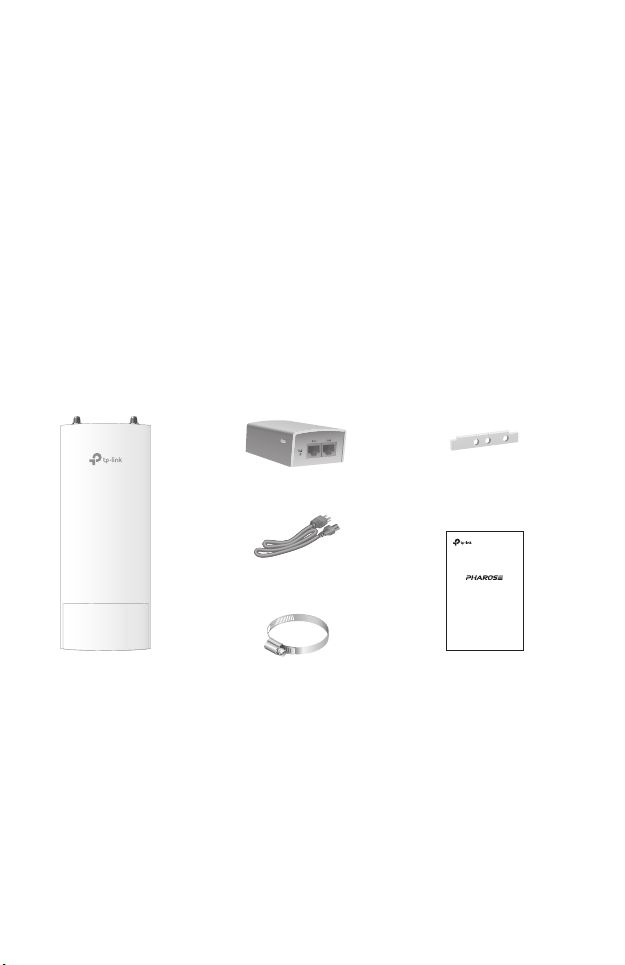
Package Contents
Base Station
Passive PoE Adapter
Power Cord
Metal Strap
1
Waterproof Rubber Insert
WBS210/WBS510
Installation Guide
Outdoor Wireless Base Station
Installation Guide

Panel Layout
The panel of Base Station
Chain1 Chain0
RESET
Shielded Ethernet
LED Explanation
AP/AP Router mode: All four LEDs remain solid.
Client/Bridge/Repeater/AP Client Router mode:
The more lit LEDs indicate the better wireless signal strength.
On: The port is connected but not active.
Flashing: The port is transmitting data.
POWERLAN0LAN1
On: The Base Station is powered on.
Port LAN1
LAN1
LAN0(POE IN)
GND
Shielded Ethernet
Port LAN0(POE IN)
Grounding Terminal
2
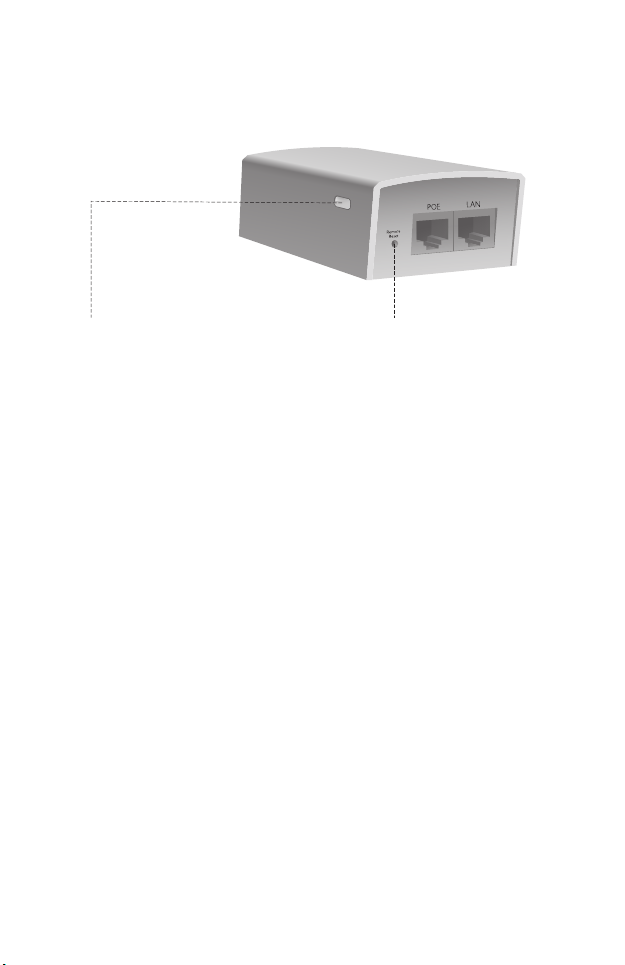
Passive PoE Adapter
Power LED:
The Power LED indicates the
status of the electric current:
Green: 0-0.8A , Red: 0.8-1A
Remote Reset:
Press and hold for 8 seconds to
reset the Base Station to its
factory defaults.
Hardware Installation
The Outdoor Wireless Base Stations require external antenna
that corresponds to your network environment. It is
recommended to buy and use TP-Link’s matching antennas.
3
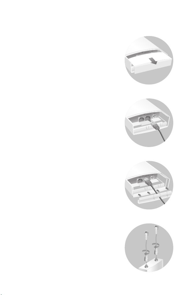
Connect Cables
Step1:
Firmly grasp the rear of the interface
cover and pull it downward.
Step2:
Use an adequate Ethernet cable to
connect the LAN0 (POE IN) port. The
length of cable is up to 60m for steady
power supply. Shielded CAT5e (or
above) cable with an integrated ground
wire is recommended.
Step3:
Affix the waterproof rubber insert
to the underside of the device for
waterproofing and replace the
cover until it firmly locks into place.
Step4:
Connect the RF Cables to the
Base Station.
4
Mount Base Station
Mount the Base Station on an antenna with a suitable mounting
bracket or on a pole for the antenna without the mounting
bracket.
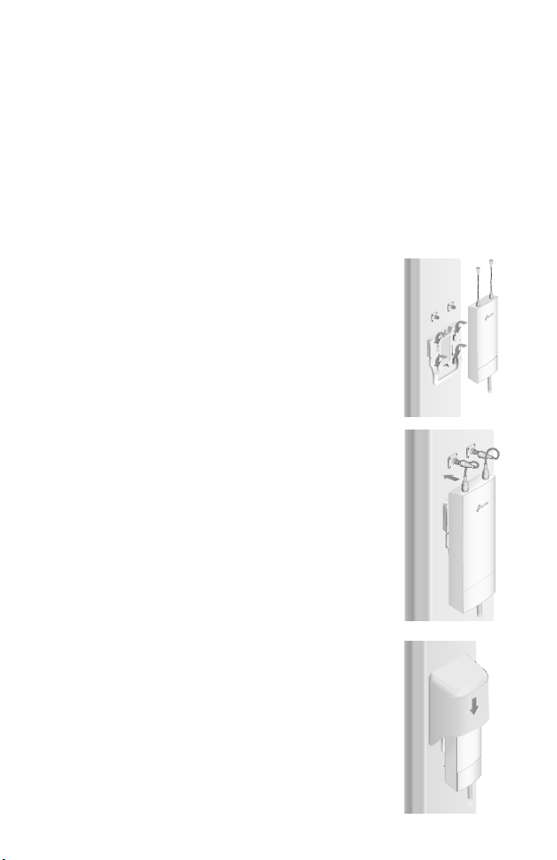
Option1: Mounting the Base Station on an Antenna
Note: Sector antenna is used as a demonstration below.
Step1:
Align the mounting tabs on the back
of the Base Station with the four slots
of the mounting bracket. Push and
slide the Base Station downward until
it locks into place.
Step2:
Connect the RF cables from the Base
Station to the corresponding
connectors on the antenna.
Step3:
Attach the protective cap. Push
and slide the protective cap down
over the Base Station until it firmly
locks into place.
5

Option 2: Mounting the Base Station on a Pole
Step1:
Loosen and completely remove the
end of the metal strap by turning the
captive screw counterclockwise with a
flathead screwdriver.
Step2:
Lead the end of the metal strap
through the back of the Base Station.
Step3:
Position the Base Station and wrap
the metal strap around the pole. Feed
the end back through the screw-block
and turn the screw clockwise to
tighten the metal strap using a
flathead screwdriver until the Base
Station is secure.
Step4:
Connect the RF cables from the Base Station to the
corresponding connectors on the antenna.
6

Power On
PoE LAN
Ethernet cable length up to 60m
Connect the Base Station to a Power over Ethernet (PoE)
adapter as follows:
Step1:
Connect the Ethernet cable from the Base Station to the POE
port of the PoE adapter.
Step2:
Connect an Ethernet cable from your LAN device (a computer,
router or switch) to the LAN port on the PoE adapter.
Step3:
Connect the power cord to the power port on the PoE adapter
and plug it into an electrical outlet.
7

Lightning and ESD Protection
Proper grounding is extremely important for outdoor devices.
There are two effective techniques for grounding the Base
Station.
Option A
Use a shielded CAT5e (or above) cable with an integrated
grounding wire for connection.
Option B
If you have the standard CAT5e cable for the connection, use a
separate grounding cable to connect the grounding Terminal
(GND) to earth ground.
Base Station
BAGrounding
Cable
Earth Ground
Grounding
Terminal
Grounding Wire
Shielded CAT5e (or above)
Cable with
an Integrated
Grounding Wire
Grounded PoE
Adapter
8
Grounded 3-wire
Power Outlet

Conguration with PharOS
Based on your network needs, this section will guide you
through the Base Station configuration using PharOS, a
web-based management system that allows you to do more
specific configurations.
Log in to the PharOS
1.
Before accessing the PharOS Web Interface, you need to
assign a static IP address 192.168.0.X (X ranges between 2
and 253, e.g. 192.168.0.10) to your computer.
2.
Open a web browser, type http://192.168.0.254 into the
address field and press Enter (Windows) or return (Mac). It is
recommended to use the latest version of Google Chrome,
Firefox or Safari.
192.168.0.254
9

3.
Enter admin for both User Name and Password, then select
the Language from the drop-down list. Read and agree the
terms of use, then click Login.
4.
Change the default User Name and Password to protect
your Base Station. Let’s start configuring the Base Staion.
For subsequent logins, use the new username and password.
Congure the Base Station
The typical topology is as follows. A wireless bridge is built
between two locations that are far from each other. Follow the
instructions below to configure the Access Point and the Client.
Access point
LAN:192.168.0.254
Client
LAN:192.168.0.2
Congure the Access Point (AP)
1. Log in to PharOS and go to the Quick Setup page.
2. Operation Mode: Select Access Point and click Next.
3. LAN Settings: Click Next.
4. Wireless AP Settings:
a. Create a new SSID (Network name) for your wireless
network.
b. Select WPA-PSK/WPA2-PSK for the Security method and
create a PSK Password to protect your AP.
c. Enter the distance between the Access Point and the
Client into the Distance Setting field.
d. Select the MAXtream checkbox (Refer to Q2 in FAQ for
details about MAXtream), and click Next.
5. Finish: Verify your settings and click Finish to complete the
configuration.
10

Congure the Client
1. Log in to PharOS and go to the Quick Setup page.
2. Operation Mode: Select Client and click Next.
3. LAN Settings: Change the IP Address to 192.168.0.X (X
ranges between 2 and 253), the same subnet with the
access point, and click Next.
4. Wireless Client Settings:
a. Click Survey and select the SSID of the Access Point in
the AP list, then click Connect.
b.
Select WPA-PSK/WPA2-PSK from the Security option,
enter the same PSK password and distance value of the
Access Point, then click Next.
5. Finish: Verify your settings and click Finish to complete the
configuration.
Installer Compliance Responsibility
Devices must be professionally installed and it is the
professional installer's responsibility to make sure the device is
operated within local country regulatory requirements.
Since PharOS can be paired with a variety of antennas, the
Antenna Gain and Output Power fields are provided to the
professional installer to assist in meeting regulatory
requirements.
11

Specication
Dimensions
Interface
Power Supply
Connector
ESD Protection
Lightning Protection
Operating Temperature
Operating Humidity
Certication
802.11 Standards
Estimation is based on copper grounding cable and shielded CAT5e(or
*
above) cable with an integrated grounding wire.
*
198*74*40mm
LAN0 (POE IN): 10/100Mbps Ethernet port
LAN1: 10/100Mbps Ethernet port
GND: Grounding terminal for lightning
protection
RESET: Button to restore the device to its
factory defaults
Chain0/Chain1: 2 RP-SMA antenna interfaces
24V passive PoE adapter included
RP-SMA Female
15kV
*
Up to 6kV
11a/n
)
℉
(WBS510)
-40 to 70 (-40 to 158
10% to 90%
CE, FCC, RoHS, IP65
11b/g/n
℃℃
(WBS210)
℉
12

FAQ
Q1.
How to restore the Base Station to its factory default
settings?
With the Base Station powered on, press and hold the
RESET button on the Base Station or the Remote Reset
button on the passive PoE adapter for about 8 seconds
until the Wireless Signal Strength LEDs flash.
What is Pharos MAXtream?
Q2.
Pharos MAXtream is a proprietary protocol developed on
the basis of Time Division Multiple Access (TDMA) by
TP-Link.
The MAXtream technology has the following advantages:
Eliminates hidden node collisions & improves channel
efficiency.
Lower latency, higher throughput, larger network capacity &
more stability.
Improves the QoS for video, voice and sound data stream.
By dividing the timing of transmission into different time
slots, MAXtream allows the Pharos devices to transmit in
rapid succession, one after another, each using its own
time slot to transmit and receive they own frames, which
greatly reduces the chance of collision.
Pharos MAXtream is a non-standard Wi-Fi protocol that is
only compatible with TP-Link’s Pharos series products.
Please notice that you will not be able to connect other
Wi-Fi devices to an AP with MAXtream enabled.
13
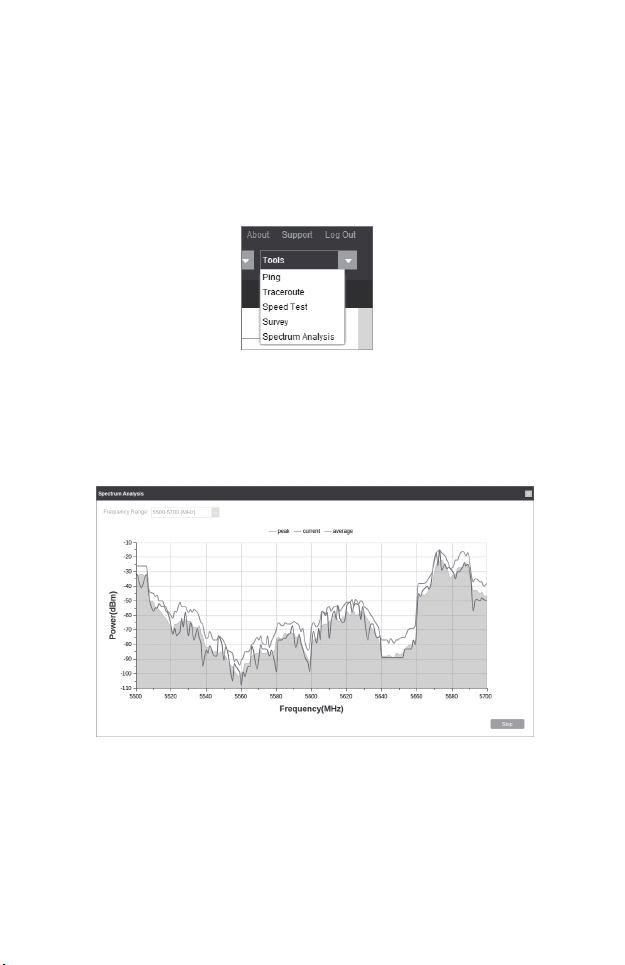
Q3.
How can I use Spectrum Analysis to find the
appropriate channel for the devices?
Log in to PharOS, click Spectrum Analysis in the tools
1.
drop-down list,
wireless connections
Click Yes to continue to the Spectrum Analysis page.
2.
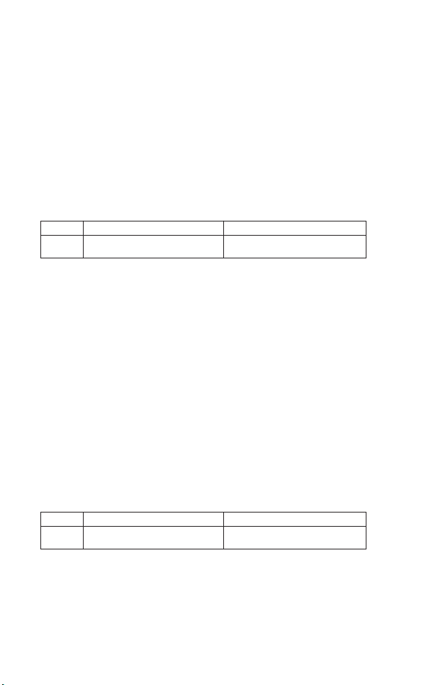
Click Start, the PharOS will begin to analyze the power of
frequency
then click stop. Note that the relatively low and continuous
part of the average curve indicates less radio noise. Here,
we use the figure below as an example.
a window will pop up to remind you that all
will be lost during spectrum analysis.
. Observe the curves for a period of time, and
Note:
The select box of Frequency Range at the top-left corner is only
available for WBS510. Select the desired range and then click Start.
3.
When choosing channel/frequency, you should avoid the
spectrum with large radio noise. In this example, the
recommended channel/ frequency is 112/5560MHz.
14
FCC STATEMENT
This equipment has been tested and found to comply with the limits for a Class A
digital device,pursuant to part 15 of the FCC Rules. These limits are designed to
provide reasonable protection against harmful interference when the equipment is
operated in a commercial environment. Thisequipment generates, uses, and can
radiate radio frequency energy and, if not installed and used in accordance with
the instruction manual, may cause harmful interference to radio communications.
Operation of this equipment in a residential area is likely to cause harmful
interference in which case the user will be required to correct the interference at
his own expense.
This device complies with part 15 of the FCC Rules. Operation is subject to the
following two conditions:
1. This device may not cause harmful interference.
2. This device must accept any interference received, including interference that
may cause undesired operation.
void the user’s authority to operate the equipment.
Note: The manufacturer is not responsible for any radio or TV interference caused
by unauthorized modifications to this equipment. Such modifications could void
the user’s authority to operate the equipment.
FCC RF Radiation Exposure Statement
This equipment complies with FCC RF radiation exposure limits set forth for an
uncontrolled environment. This device and its antenna must not be co-located or
operating in conjunction with any other antenna or transmitter.
“To comply with FCC RF exposure compliance requirements, this grant is
applicable to only Mobile Configurations. The antennas used for this transmitter
must be installed to provide a separation distance of at least 20 cm from all
persons and must not be co-located or operating in conjunction with any other
antenna or transmitter.”
CE Mark Warning
RF Exposure Information
This device meets the EU requirements (1999/5/EC Article 3.1a) on the limitation of
exposure of the general public to electromagnetic fields by way of health
protection.
This is a class A product. In a domestic environment, this product may cause radio
interference, in which case the user may be required to take adequate measures.
IC STATEMENT
This Class A digital apparatus complies with Canadian ICES-003.
Cet appareil numérique de la classe A est conforme à la norme NMB-003 du Canada.
Canadian Compliance Statement
Canadian Compliance Statement
This device complies with Industry Canada license-exempt RSSs. Operation is
subject to the following two conditions:
1) This device may not cause interference, and
2) This device must accept any interference, including interference that may
cause undesired operation of the device.
This radio transmitter (IC: 8853A-WBS210/Model: WBS210 and IC:
8853A-WBS510/Model: WBS510) has been approved by Industry Canada to
operate with the antenna types listed below with the maximum permissible gain
and required antenna impedance for each antenna type indicated. Antenna types
not included in this list, having a gain greater than the maximum gain indicated for
that type, are strictly prohibited for use with this device.
Model
Antenna
To reduce potential radio interference to other users, the antenna type and its gain
should be so chosen that the equivalent isotropically radiated power (e.i.r.p.) is not
more than that permitted for successful communication.
Le présent appareil est conforme aux CNR d’Industrie Canada applicables aux
appareils radio exempts de licence. L’exploitation est autorisée aux deux
conditions suivantes :
1) l’appareil ne doit pas produire de brouillage;
2) l’utilisateur de l’appareil doit accepter tout brouillage radioélectrique subi,
meme si le brouillage est susceptible d’en compromettre le fonctionnement.
Cet émetteur radio (IC: 8853A-WBS210/Model: WBS210 and IC:
8853A-WBS510/Model: WBS510) a été approuvée par Industrie Canada pour
l’exploitation avec l’antenne types énumérés ci-dessous avec le gain maximal
admissible et requis l’impédance de l’antenne pour chaque type d’antenne indiqué.
Types d’antenne non inclus dans cette liste, ayant un gain supérieur au gain
maximal indiqué pour ce type, sont strictement interdits pour une utilisation avec
cet appareil. Immédiatement suite à la remarque, le fabricant doit fournir une liste
de tous les types d’antenne approuvé pour une utilisation avec l’émetteur, ce qui
indique le gain
maximal d’antenne permis (en dBi) et requis d’impédance pour chacun.
Model
Antenna
Pour réduire le risque d’interférence aux autres utilisateurs, le type d’antenne et son
gain doivent être choisies de façon que la puissance isotrope rayonnée
équivalente (PIRE) ne dépasse pas ce qui est nécessaire pour une communication
réussie.
WBS210 (8853A-WBS210)
2 dBi omni (50 ohm)
15 dBi sector (50 ohm)
WBS210 (8853A-WBS210)
2 dBi omni (50 ohm)
15 dBi sector (50 ohm)
WBS510 (8853A-WBS510)
3 dBi omni (50 ohm)
19 dBi sector (50 ohm)
WBS510 (8853A-WBS510)
3 dBi omni (50 ohm)
19 dBi sector (50 ohm)

Caution (For WBS510)
1) The device for operation in the band 5150–5250 MHz is only for indoor use to
reduce the potential for harmful interference to co-channel mobile satellite
systems;
2) For devices with detachable antenna(s), the maximum antenna gain permitted
for devices in the band 5725-5850 MHz shall be such that the equipment still
complies with the e.i.r.p. limits specified for point-to-point and non-point-to-point
operation as appropriate.
Avertissement (For WBS510)
1) Le dispositif fonctionnant dans la bande 5150-5250 MHz est réservé
uniquement pour une utilisation à l’intérieur afin de réduire les risques de brouillage
préjudiciable aux systèmes de satellites mobiles utilisant les mêmes canaux;
2) Le gain maximal d'antenne permis pour les dispositifs avec antenne(s)
amovible(s) utilisant la bande 5725-5850 MHz doit se conformer à la limitation
P.I.R.E spécifiée pour l’exploitation point à point et non point à point, selon le cas.
Radiation Exposure Statement
This equipment complies with IC radiation exposure limits set forth for an
uncontrolled environment. This equipment should be installed and operated with
minimum distance 20cm between the radiator & your body.
Déclaration d'exposition aux radiations
Cet équipement est conforme aux limites d'exposition aux rayonnements IC
établies pour un environnement non contrôlé. Cet équipement doit être installé et
utilisé avec un minimum de 20 cm de distance entre la source de rayonnement et
votre corps.
Industry Canada Statement
CAN ICES-3 (A)/NMB-3(A)

Safety Information
When product has a power button, the power button is one of the way to shut
•
off the product; When there is no power button, the only way to completely shut
off power is to disconnect the product or the power adapter from the power
source.
Don’t disassemble the product, or make repairs yourself. You run the risk of
•
electric shock and voiding the limited warranty. If you need service, please
contact us.
Avoid water and wet locations.
•
Use only power supplies which are provided by manufacturer and in the
•
original packing of this product. If you have any questions, please don't hesitate
to contact us.
NCC Notice & BSMI Notice
注意!
依據 低功率電波輻射性電機管理辦法
第十二條 經型式認證合格之低功率射頻電機,非經許可,公司、商號或使用者
均不得擅自變更頻率、加大功率或變更原設計之特性或功能。
第十四條 低功率射頻電機之使用不得影響飛航安全及干擾合法通行;經發現有
干擾現象時,應立即停用,並改善至無干擾時方得繼續使用。前項合法通信,
指依電信規定作業之無線電信。低功率射頻電機需忍受合法通信或工業、科學
以及醫療用電波輻射性電機設備之干擾。
安全諮詢及注意事項
請使用原裝電源供應器或只能按照本產品注明的電源類型使用本產品。
● 清潔本產品之前請先拔掉電源線。請勿使用液體、噴霧清潔劑或濕布進行清潔。
● 注意防潮,請勿將水或其他液體潑灑到本產品上。
● 插槽與開口供通風使用,以確保本產品的操作可靠並防止過熱,請勿堵塞或覆
蓋開口。
● 請勿將本產品置放於靠近熱源的地方。除非有正常的通風,否則不可放在密閉
位置中。
● 請不要私自打開機殼,不要嘗試自行維修本產品,請由授權的專業人士進行此
項工作。
此為甲類資訊技術設備,于居住環境中使用時,可能會造成射頻擾動,在此種
情況下,使用者會被要求採取某些適當的對策。
For EU/EFTA, this product can be used in the following countries (For WBS510):
AT / BE / BG / CH / CY / CZ / DE / DK / EE / ES / FI / FR / GB / GR / HR / HU
/ IE / IS / IT / LI / LT / LV / MT / NL / NO / PL / PT / RO / SE / SI / SK
Продукт сертифіковано згідно с правилами системи УкрСЕПРО на відповідність вимогам
нормативних документів та вимогам, що передбачені чинними законодавчими актами
України.
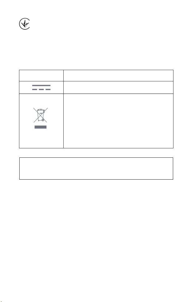
Explanation of the symbols on the product label
Symbol Explanation
DC voltage
RECYCLING
This product bears the selective sorting symbol for Waste
electrical and electronic equipment (WEEE). This means that
this product must be handled pursuant to European directive
2012/19/EU in order to be recycled or dismantled to minimize
its impact on the environment.
User has the choice to give his product to a competent
recycling organization or to the retailer when he buys a new
electrical or electronic equipment.
この装置は、クラスA情報技術装置です。この装置を家庭環境で使用すると
電波妨害を引き起こすことがあります。この場合には使用者が適切な対策を
講ずるよう要求されることがあります。 VCCI-A
 Loading...