

Page 1

TL-WA7510N
5GHz 150Mbps Indoor/ Outdoor Wireless Access Point
Rev: 1.0.0
1910010534
Page 2

COPYRIGHT & TRADEMARKS
Specifications are subject to change without notice. is a registered trademark
of TP-LINK TECHNOLOGIES CO., LTD. Other brands and product names are trademarks or
registered trademarks of their respective holders.
No part of the specifications may be reproduced in any form or by any means or used to make any
derivative such as translation, transformation, or adaptation without permission from TP-LINK
TECHNOLOGIES CO., LTD. Copyright © 2012 TP-LINK TECHNOLOGIES CO., LTD. All rights
reserved.
http://www.tp-link.com
Page 3

FCC STATEMENT
This equipment has been tested and found to comply with the limits for a Class B digital device,
pursuant to part 15 of the FCC Rules. These limits are designed to provide reasonable protection
against harmful interference in a residential installation. This equipment generates uses and can
radiate radio frequency energy and, if not installed and used in accordance with the instructions,
may cause harmful interference to radio communications. However, there is no guarantee that
interference will not occur in a particular installation. If this equipment does cause harmful
interference to radio or television reception, which can be determined by turning the equipment off
and on, the user is encouraged to try to correct the interference by one or more of the following
measures:
x Reorient or relocate the receiving antenna.
x Increase the separation between the equipment and receiver.
x Connect the equipment into an outlet on a circuit different from that to which the receiver is
connected.
x Consult the dealer or an experienced radio/ TV technician for help.
This device complies with part 15 of the FCC Rules. Operation is subject to the following two
conditions:
1) This device may not cause harmful interference.
2) This device must accept any interference received, including interference that may cause
undesired operation.
Any changes or modifications not expressly approved by the party responsible for compliance
could void the user’s authority to operate the equipment.
Note: The manufacturer is not responsible for any radio or TV interference caused by
unauthorized modifications to this equipment. Such modifications could void the user’s authority
to operate the equipment.
FCC RF Radiation Exposure Statement
This equipment complies with FCC RF radiation exposure limits set forth for an uncontrolled
environment. This device and its antenna must not be co-located or operating in conjunction with
any other antenna or transmitter.
“To comply with FCC RF exposure compliance requirements, this grant is applicable to only
Mobile Configurations. The antennas used for this transmitter must be installed to provide a
separation distance of at least cm from all persons and must not be co-located or operating in
conjunction with any other antenna or transmitter.”
CE Mark Warning
This is a class B product. In a domestic environment, this product may cause radio interference, in
which case the user may be required to take adequate measures.
Page 4

Industry Canada Statement:
This device complies with RSS-210 of the Industry Canada Rules. Operation is subject to the
following two conditions:
(1)This device may not cause harmful interference, and
(2)This device must accept any interference received, including interference that may cause
undesired operation.
IMPORTANT NOTE:
Radiation Exposure Statement:
This equipment complies with Canada radiation exposure limits set forth for an uncontrolled
environment. This equipment should be installed and operated with minimum distance 20cm
between the radiator & your body.
Ce dispositif est conforme à la norme CNR-210 d’Industrie Canada applicable aux appareils radio
exempts de licence. Son fonctionnement est sujet aux deux conditions suivantes:
(1) Le dispositif ne doit pas produire de brouillage préjudiciable, et
(2) Ce dispositif doit accepter tout brouillage reçu,y compris un brouillage susceptible de
provoquer un fonctionnement indésirable.
NOTE IMPORTANTE:
Déclaration d’exposition aux radiations:
Cet équipement est conforme aux limites d’exposition aux rayonnements IC établies pour un
environnement non contrôlé. Cet équipement doit être installé et utilisé avec un minimum de 20
cm de distance entre la source de rayonnement et votre corps.
Korea Warning Statements:
╏䟊 ⶊ㍶㍺゚⓪ 㤊㣿㭧 㩚䕢䢒㔶 Ṗ⓻㎇㧊 㧞㦢UG
NCC Notice:
㍧ൟᓣ䁡䄝ড়ḐПԢࡳ⥛ᇘ丏䳏″ˈ䴲㍧䀅ৃˈ݀ৌǃଚ㰳Փ⫼㗙ഛϡᕫ᪙㞾䅞丏⥛ǃࡴࡳ
⥛䅞䀁㿜П⡍ᗻঞࡳ㛑DŽ
Ԣࡳ⥛ᇘ丏䳏″ПՓ⫼ϡᕫᕅ䷓亯㟾ᅝܼঞᑆড়⊩䗮ֵ˗㍧ⱐ⧒᳝ᑆ⧒䈵ᰖˈឝゟذ⫼ˈϺ
ᬍ㟇⛵ᑆᰖᮍᕫ㑐㑠Փ⫼DŽࠡ䷙ড়⊩䗮ֵˈᣛձ䳏ֵ⊩㽣ᅮὁП⛵㎮䳏䗮ֵDŽԢࡳ⥛ᇘ丏䳏
″䷜ᖡফড়⊩䗮ֵᎹὁǃ⾥ᅌঞ䝿Ⱆ⫼䳏⊶䔏ᇘᗻ䳏″䀁٭ПᑆDŽ
Page 5

TP-LINK TECHNOLOGIES CO., LTD
DECLARATION OF CONFORMITY
For the following equipment:
Product Description: 5GHz 150Mbps Indoor/ Outdoor Wireless Access Point
Model No.: TL-WA7510N
Trademark: TP-LINK
We declare under our own responsibility that the above products satisfy all the technical
regulations applicable to the product within the scope of Council Directives:
Directives 1999/5/EC, Directives 2004/108/EC, Directives 2006/95/EC, Directives 1999/519/EC,
Directives 2011/65/EU
The above product is in conformity with the following standards or other normative documents
ETSI EN 300 328 V1.7.1: 2006
ETSI EN 301 489-1 V1.8.1:2008& ETSI EN 301 489-17 V2.1.1:2009
EN 55022:2006 +A1:2007
EN 55024:1998+A1:2001+A2:2003
EN 61000-3-2:2006+A1:2009+A2:2009
EN 61000-3-3:2008
EN60950-1:2006+A11:2009+A1:2010
EN62311:2008
The product carries the CE Mark:
Person is responsible for marking this declaration:
Yang Hongliang
Product Manager of International Business
Date of issue: 2012
TP-LINK TECHNOLOGIES CO., LTD.
Building 24 (floors 1, 3, 4, 5), and 28 (floors 1-4) Central Science and Technology Park,
Shennan Rd, Nanshan, Shenzhen, China
Page 6

CONTENTS
Package Contents ....................................................................................................1
Chapter 1 Introduction.........................................................................................2
1.1 Product Overview ............................................................................................ 2
1.2 Conventions ....................................................................................................2
1.3 Main Features .................................................................................................2
1.4 Panel Layout ...................................................................................................3
1.4.1 The Rear Panel ...............................................................................................3
1.4.2 The Front Panel...............................................................................................4
Chapter 2 Connecting the Device .......................................................................5
2.1 System Requirements ..................................................................................... 5
2.2 Installation Environment Requirements........................................................... 5
2.3 Connecting the Device .................................................................................... 5
2.3.1 Standard AP Mode ..........................................................................................5
2.3.2 AP Router Mode ..............................................................................................9
2.3.3 AP Client Router Mode................................................................................. 10
Chapter 3 Quick Installation Guide...................................................................11
3.1 Configuring the PC ........................................................................................11
3.2 Quick Setup................................................................................................... 14
3.2.1 Standard AP Mode ....................................................................................... 16
3.2.2 AP Router Mode ........................................................................................... 26
3.2.3 AP Client Router Mode................................................................................. 29
Chapter 4 Configuring Standard AP Mode.......................................................32
4.1 Login..............................................................................................................32
4.2 Status ............................................................................................................ 33
4.3 Quick Setup................................................................................................... 34
4.4 QSS............................................................................................................... 34
4.5 Operation Mode............................................................................................. 40
4.6 Network ......................................................................................................... 40
4.7 Wireless.........................................................................................................41
4.7.1 Wireless Settings.......................................................................................... 42
4.7.2 Wireless Security.......................................................................................... 42
4.7.3 Wireless MAC Filtering ................................................................................. 54
4.7.4 Wireless Advanced....................................................................................... 56
I
Page 7

4.7.5 Antenna Alignment ....................................................................................... 58
4.7.6 Distance Settings.......................................................................................... 58
4.7.7 Throughput Monitor ...................................................................................... 59
4.7.8 Wireless Statistics ........................................................................................ 59
4.8 DHCP ............................................................................................................ 60
4.8.1 DHCP Settings ............................................................................................. 61
4.8.2 DHCP Clients List......................................................................................... 62
4.8.3 Address Reservation .................................................................................... 62
4.9 System Tools................................................................................................. 64
4.9.1 SNMP ........................................................................................................... 64
4.9.2 Diagnostic ..................................................................................................... 66
4.9.3 Ping Watch Dog............................................................................................ 67
4.9.4 Speed Test ................................................................................................... 68
4.9.5 Firmware Upgrade........................................................................................ 69
4.9.6 Factory Defaults ........................................................................................... 70
4.9.7 Backup & Restore......................................................................................... 71
4.9.8 Reboot .......................................................................................................... 71
4.9.9 Password...................................................................................................... 72
4.9.10 System Log................................................................................................... 73
Chapter 5 Configuring AP Router & AP Client Router Mode..........................74
5.1 Login..............................................................................................................74
5.2 Status ............................................................................................................ 75
5.3 Quick Setup................................................................................................... 78
5.4 QSS............................................................................................................... 78
5.5 Operation Mode............................................................................................. 84
5.6 Network ......................................................................................................... 84
5.6.1 LAN............................................................................................................... 85
5.6.2 WAN ............................................................................................................. 85
5.6.3 MAC Clone ................................................................................................... 95
5.7 Wireless.........................................................................................................96
5.7.1 Wireless Settings.......................................................................................... 96
5.7.2 Wireless Security........................................................................................ 103
5.7.3 Wireless MAC Filtering ............................................................................... 104
5.7.4 Wireless Advanced..................................................................................... 107
5.7.5 Antenna Alignment ..................................................................................... 108
II
Page 8

5.7.6 Distance Settings........................................................................................ 109
5.7.7 Throughput Monitor .................................................................................... 109
5.7.8 Wireless Statistics ...................................................................................... 110
5.8 DHCP .......................................................................................................... 111
5.8.1 DHCP Settings ........................................................................................... 112
5.8.2 DHCP Clients List....................................................................................... 113
5.8.3 Address Reservation .................................................................................. 113
5.9 Forwarding ..................................................................................................115
5.9.1 Virtual Servers ............................................................................................ 115
5.9.2 Port Triggering............................................................................................ 117
5.9.3 DMZ ............................................................................................................ 120
5.9.4 UPnP .......................................................................................................... 121
5.10 Security .......................................................................................................122
5.10.1 Basic Security............................................................................................. 122
5.10.2 Advanced Security...................................................................................... 123
5.10.3 Local Management ..................................................................................... 125
5.10.4 Remote Management ................................................................................. 126
5.11 Parental Control ..........................................................................................127
5.12 Access Control ............................................................................................129
5.12.1 Rule ............................................................................................................ 129
5.12.2 Host ............................................................................................................ 131
5.12.3 Target ......................................................................................................... 132
5.12.4 Schedule..................................................................................................... 133
5.13 Static Routing .............................................................................................. 135
5.14 Bandwidth Control ....................................................................................... 136
5.14.1 Control Settings .......................................................................................... 136
5.14.2 Rules List .................................................................................................... 137
5.15 IP& MAC Binding......................................................................................... 137
5.15.1 Binding Settings.......................................................................................... 138
5.15.2 ARP List...................................................................................................... 139
5.16 Dynamic DNS..............................................................................................139
5.17 System Tools............................................................................................... 143
5.17.1 Time Settings.............................................................................................. 143
5.17.2 Diagnostic ................................................................................................... 144
5.17.3 Firmware Upgrade...................................................................................... 146
5.17.4 Factory Defaults ......................................................................................... 147
III
Page 9

5.17.5 Backup & Restore....................................................................................... 148
5.17.6 Reboot ........................................................................................................ 148
5.17.7 Password .................................................................................................... 149
5.17.8 System log .................................................................................................. 150
5.17.9 Statistics ..................................................................................................... 152
Appendix A: FAQ..................................................................................................154
Appendix B: Factory Defaults .............................................................................159
Appendix C: Specifications .................................................................................160
Appendix D: Glossary ..........................................................................................161
IV
Page 10

TL-WA7510N 5GHz 150Mbps Indoor/ Outdoor Wireless Access Point User Guide
Package Contents
The following items should be found in your package:
One TL-WA7510N 5GHz 150Mbps Indoor/ Outdoor Wireless Access Point
One Power Injector
Ethernet Cable
One Power Adapter for TL-WA7510N 5GHz 150Mbps Indoor/ Outdoor Wireless Access Point
Mounting Kits
Quick Installation Guide
One Resource CD for TL-WA7510N 5GHz 150Mbps Indoor/ Outdoor Wireless Access Point,
including:
This User Guide
Other helpful information
Note:
Make sure that the package contains the above items. If any of the listed items is damaged or
missing, please contact with your distributor.
Use only power supplies listed in this user manual.
1
Page 11

TL-WA7510N 5GHz 150Mbps Indoor/ Outdoor Wireless Access Point User Guide
Chapter 1 Introduction
1.1 Product Overview
The TL-WA7510N 5GHz 150Mbps Indoor/ Outdoor Wireless Access Point allows you to connect
your network with other wireless devices wirelessly, sharing Internet Access, files and fun, easily
and securely. The high power design will also help you build a more stable link or cover more area.
The TL-WA7510N 5GHz 150Mbps Indoor/ Outdoor Wireless Access Point provides three operation
modes for multi-users to access the Internet: Standard AP, AP Router and AP Client Router. In
Standard AP mode, it can work in various modes, such as Access
Point/Multi-SSID/Client/Repeater/Universal Repeater/ Bridge with AP. In AP Router mode, it can
access the Internet via an ADSL/Cable Modem, while sharing data wirelessly. In AP Client Router
mode, it works as a WISP CPE and can access the Internet wirelessly via your WISP.
With the most attentive wireless security, the TL-WA7510N 5GHz 150Mbps Indoor/ Outdoor
Wireless Access Point provides multiple protection measures. It can be set to turn off wireless
network name (SSID) broadcast so that only stations that have the SSID can be connected. The AP
provides wireless LAN 64/128/152-bit WEP encryption security, and WPA/WPA2 and
WPA-PSK/WPA2-PSK authentication, as well as TKIP/AES encryption security. It also supports
VPN pass-through for sensitive data secure transmission.
The TL-WA7510N 5GHz 150Mbps Indoor/ Outdoor Wireless Access Point complies with the IEEE
802.11a, IEEE 802.11n standards so that the data transmission rate is up to 150 Mbps.
1.2 Conventions
The AP, TL-WA7510N, or Device mentioned in this User guide stands for TL-WA7510N 5GHz
150Mbps Indoor/ Outdoor Wireless Access Point without any explanations.
Parameters provided in the pictures are just references for setting up the product, which may differ
from the actual situation. You can set the parameters according to your demand.
1.3 Main Features
¾ Complies with IEEE 802.11a, IEEE 802.11n, IEEE 802.3, IEEE 802.3u, IEEE 802.1x, IEEE
802.3x, IEEE 802.11i, IEEE 802.11e
¾ Wireless Data transfer rates up to 150 Mbps
¾ Supports Standard AP, AP Router and AP Client Router operation mode
¾ High output transmit power and receive sensitivity optimized
¾ Supports AP Client Router Mode for WISP CPE
¾ Supports passive power over Ethernet
2
Page 12

¾ Supports Wireless Distribution System (WDS)
¾ Supports Antenna Alignment
¾ Provides throughput monitor indicating the current wireless throughput
¾ Supports Layer 2 User Isolation
¾ Supports Ping Watch Dog
¾ Supports link speed test
¾ Supports Remote Management
¾ Output transmit power adjustable
¾ Supports PPPoE, Dynamic IP, Static IP, L2TP, PPTP and BigPond Cable Internet Access
¾ Built-in NAT and DHCP server supporting static IP address distributing
¾ Supports UPnP, Dynamic DNS, Static Routing, VPN Pass-through
TL-WA7510N 5GHz 150Mbps Indoor/ Outdoor Wireless Access Point User Guide
(BigPond Cable Internet Access is only available in AP Router mode.)
¾ Supports Virtual Server, Special Application and DMZ host
¾ Built-in firewall supporting IP address filtering, Domain Name filtering, and MAC address
filtering
¾ Provides WLAN ACL (Access Control List)
¾ Supports configuration backup/restore and firmware upgrade
¾ Supports Web management
1.4 Panel Layout
1.4.1 The Rear Panel
Figure 1-1 Rear Panel sketch
View from left to right, the parts are explained below.
¾ RP-SMA: This is where you can connect an outside antenna. For this AP, the antenna is built
3
Page 13
)
¾ LAN: This port is used to connect to the POE port of the provided Power Injector.
¾ Reset:
Ensure the AP is powered on before it restarts completely.
TL-WA7510N 5GHz 150Mbps Indoor/ Outdoor Wireless Access Point User Guide
inside, and usually there is no necessity to connect an outside one.
There are two ways to reset the AP’s factory defaults:
x Use the Factory Defaults function on System Tools -> Factory Defaults page in the
AP’s Web-based Utility.
x Use the Factory Default Reset button: Press and hold the Reset button until Wireless
Signal Strength LEDs flash, and then the AP will reboot.
Note:
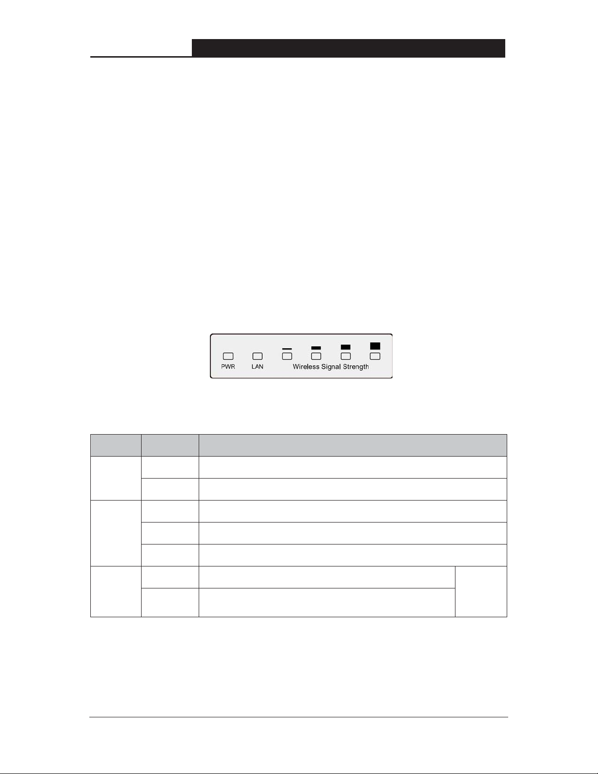
1.4.2 The Front Panel
TL-WA7510N consists of several LED indicators, which is designed to indicate connections and
wireless signal.
Figure 1-2 Front Panel sketch
View from left to right, the details are explained below.
Name Status Indication
Off No Power
PWR
On Power on
Off There is no device linked to the corresponding port
LAN
Signal
Strength
On There is a device linked to the corresponding port but no activity
Flashing There is an active device linked to the corresponding port
Off There is no remote wireless signal Wireless
On Indicates the wireless signal strength of a remote AP
Table 1-1 the LED Description
Client or
Repeater
mode
4
Page 14

TL-WA7510N 5GHz 150Mbps Indoor/ Outdoor Wireless Access Point User Guide
Chapter 2 Connecting the Device
2.1 System Requirements
¾ Each PC in the LAN needs a working Ethernet Adapter and an Ethernet cable with RJ45
connectors.
¾ TCP/IP protocol must be installed on each PC.
¾ Web browser, such as Microsoft Internet Explorer 5.0 or later, Netscape Navigator 6.0 or
later.
¾ If the device is configured to AP client router mode, you also need:
Wireless Internet Access Service (WISP).
¾ If the device is configured to AP router mode, you also need:
Broadband Internet Access Service (DSL/Cable/Ethernet).
¾ One DSL/Cable Modem that has an RJ45 connector (you do not need it if you connect the
router to the Ethernet.).
2.2 Installation Environment Requirements
¾ Operating temperature: -30ć~70ć
¾ Operating Humidity: 10%~90% RH, Non-condensing
2.3 Connecting the Device
To connect the AP, please follow the steps below:
1. Power off your PC, Cable/DSL Modem, and the AP.
2. Locate an optimum location for the AP. The best place is usually at the center of your wireless
network. The place must accord with the Installation Environment Requirements
3. Adjust the direction of the antenna. Normally, upright is a good direction.
After finishing the steps above, please choose the operation mode you need and carry out the
corresponding steps. There are three operation mode supported by this AP: Standard AP, AP
Router, and AP Client Router.
2.3.1 Standard AP Mode
.
In this mode, the device enables multi-users to access, and provides several wireless modes,
including Access Point, Multi-SSID, Client, Repeater, Universal Repeater, and Bridge with AP.
These six modes are illustrated as below:
5
Page 15
TL-WA7510N 5GHz 150Mbps Indoor/ Outdoor Wireless Access Point User Guide
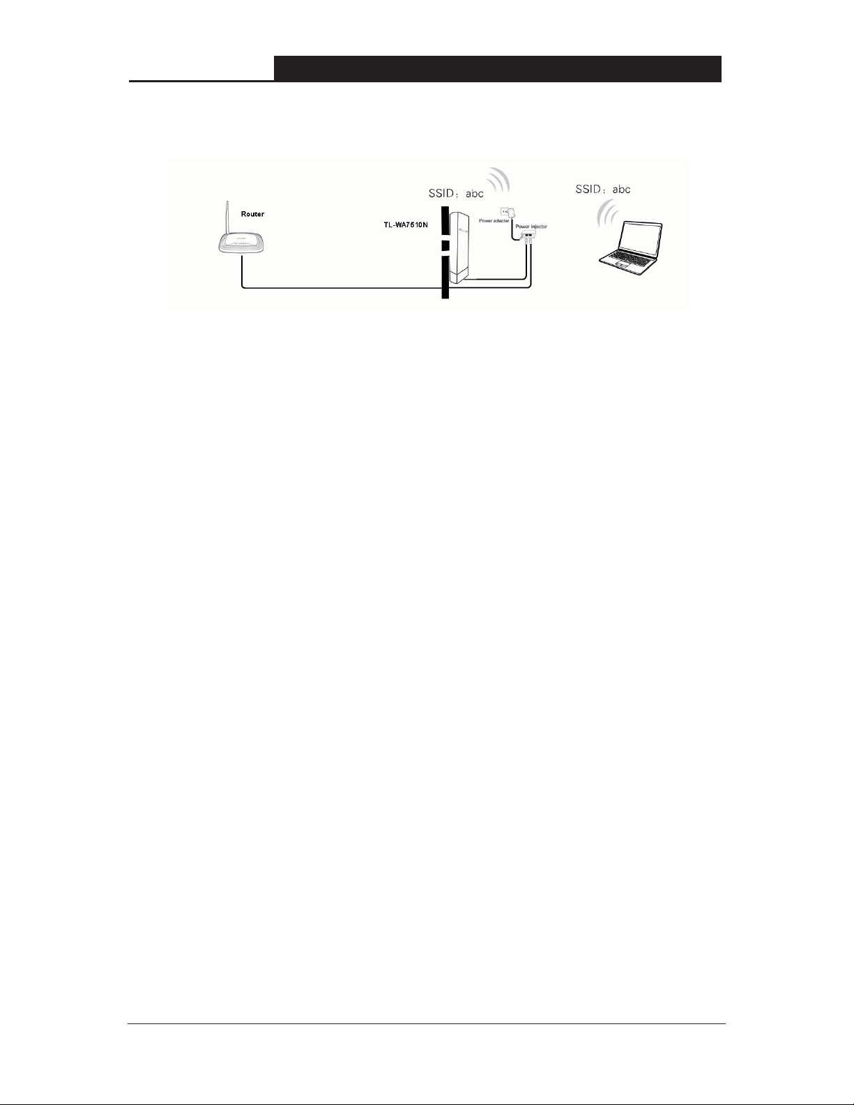
¾ Access Point
This operation mode allows wireless stations to access.
Figure 2-1 Hardware Installation of the TL-WA7510N in Access Point mode
1. Connect the LAN port of TL-WA7510N to the POE port of the Power Injector with an Ethernet
cable.
2. Connect the LAN port of the Power Injector to the wired network port with an Ethernet cable.
3. Plug one end of the Power Adapter into the DC jack on the Power Injector, and the other end
in the electrical wall socket.
4. Power on the notebook(s) and other connected devices (such as the Router).
¾ Multi-SSID
In this mode, AP can support up to 4 SSID.
6
Page 16

TL-WA7510N 5GHz 150Mbps Indoor/ Outdoor Wireless Access Point User Guide
Figure 2-2 Hardware Installation of the TL-WA7510N in Multi-SSID mode
1. Connect the LAN port of TL-WA7510N to the POE port of the Power Injector with an Ethernet
cable.
2. Connect the LAN port of the Power Injector to the wired network port with an Ethernet cable.
3. Plug one end of the Power Adapter into the DC jack on the Power Injector, and the other end
in the electrical wall socket.
4. Power on the notebooks and other connected devices (such as the Router).
¾ Client
Figure 2-3 Hardware Installation of the TL-WA7510N in Client mode
7
Page 17

)
1. Connect the LAN port of TL-WA7510N to the POE port of the Power Injector with an Ethernet
2. Connect the PC to the LAN port of the Power Injector with an Ethernet cable.
3. Plug one end of the Power Adapter into the DC jack on the Power Injector, and the other end
4. Power on the PC(s) and other connected devices (such as the Router).
¾ Repeater and Universal Repeater
TL-WA7510N 5GHz 150Mbps Indoor/ Outdoor Wireless Access Point User Guide
cable.
in electrical wall socket.
Figure 2-4 Hardware Installation of the TL-WA7510N in (Universal) Repeater mode
1. Connect the LAN port of TL-WA7510N to the POE port of the Power Injector with an Ethernet
cable.
2. Plug one end of the Power Adapter into the DC jack on the Power Injector, and the other end
in electrical wall socket.
3. Power on the PC(s) and other connected devices (such as the Router).
Note:
Both Repeater and Universal Repeater modes allow the AP with its own BSS to relay data to a
root AP. The wireless repeater relays signal between its stations and the root AP for greater
wireless range. However, in Repeater mode, the WDS associated is enabled, while in Universal
Repeater mode, the WDS associated is disabled.
¾ Bridge with AP
Two Devices are needed in this mode.
8
Page 18

)
)
1. Connect the LAN port of TL-WA7510N to the POE port of the Power Injector with an Ethernet
2. Plug one end of the Power Adapter into the DC jack on the Power Injector, and the other end
3. Power on the PC(s).
TL-WA7510N 5GHz 150Mbps Indoor/ Outdoor Wireless Access Point User Guide
Figure 2-5 Hardware Installation of the TL-WA7510N in Standard AP -- Bridge mode
cable.
in electrical wall socket.
Note:
It is recommended that you connect a PC/notebook to the LAN port of the Device with an Ethernet
cable, and then login the Device from the PC/notebook to set the Device in Bridge with AP mode.
2.3.2 AP Router Mode
Figure 2-6 Hardware Installation of the TL-WA7510N in AP Router mode
1. Connect the LAN port of TL-WA7510N to the POE port of the Power Injector with an Ethernet
cable.
2. Connect the DSL/Cable Modem to the LAN port of the Power Injector with an Ethernet cable.
3. Plug one end of the Power Adapter into the DC jack on the Power Injector, and the other end
in electrical wall socket.
4. Power on the PC(s) and other connected devices (such as the ADSL modem).
Note:
In this mode, the LAN port of the Power Injector (connected to the LAN port of the Device) works
as the WAN port.
9
Page 19

TL-WA7510N 5GHz 150Mbps Indoor/ Outdoor Wireless Access Point User Guide
2.3.3 AP Client Router Mode
Figure 2-7 Hardware Installation of the TL-WA7510N in AP Client Router mode
1. Connect the LAN port of TL-WA7510N to the POE port of the Power Injector with an Ethernet
cable.
2. Connect the PC to the LAN port of the Power Injector with an Ethernet cable.
3. Plug one end of the Power Adapter into the DC jack on the Power Injector, and the other end
in electrical wall socket.
4. Power on the PC(s) and notebook(s).
10
Page 20

TL-WA7510N 5GHz 150Mbps Indoor/ Outdoor Wireless Access Point User Guide
Chapter 3 Quick Installation Guide
3.1 Configuring the PC
This chapter will guide you to configure your PC to communicate with the AP. The wireless
adapter-equipped computers in your network must be in the same IP Address range without
overlapping with each other. Manually configure the IP address as 192.168.1.* (* is any number
within 1 to 253), and the Subnet mask as 255.255.255.0 for your PC following the instructions
below.
Connect the local PCs to the LAN ports on the AP and configure the IP address manually for your
PCs.
1. Click Start (in the lower left corner of the screen), right-click My Network Connections and
choose Properties.
Figure 3-1
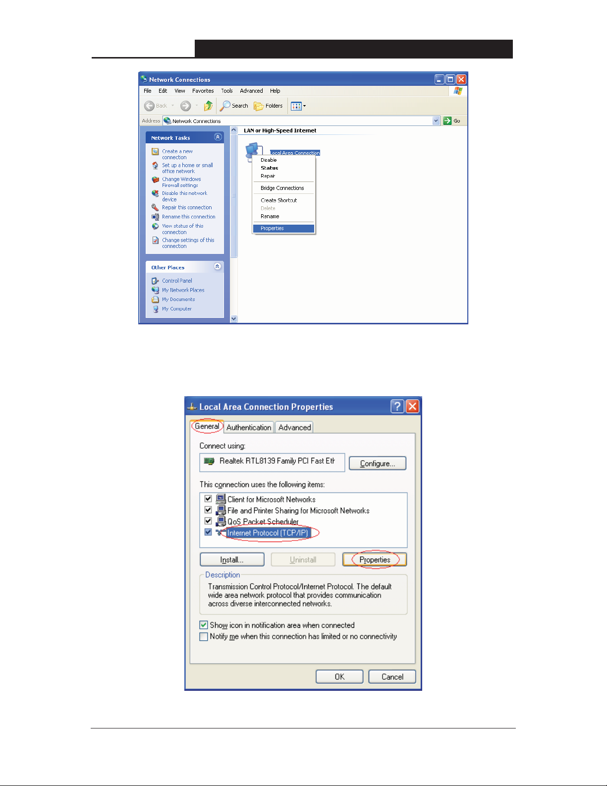
2. On the My Network Connections window shown as Figure 3-2 below, right-click LAN (
Area Connection) and choose Properties.
11
Local
Page 21
TL-WA7510N 5GHz 150Mbps Indoor/ Outdoor Wireless Access Point User Guide
Figure 3-2
3. In the General tab of Internet Protocol (TCP/IP) Properties window, highlight Internet Protocol
(TCP/IP) and click Properties.
Figure 3-3
12
Page 22

TL-WA7510N 5GHz 150Mbps Indoor/ Outdoor Wireless Access Point User Guide
4. Configure the IP address manually.
1) Select Use the following IP address.
2) Enter 192.168.1.* (* is any integer between 1 to 253) into the IP address filed,
255.255.255.0 into the Subnet mask filed.
3) Click OK to keep your settings.
Figure 3-4
5. Verify the network connection between your PC and the AP via the Ping command. The
following example is in Windows XP Operating System.
1) Click Start > Run tab. Enter cmd in the filed and click OK.
2) Type ping 192.168.1.254 on the screen that displays and then press Enter.
3) If the result displayed is similar to that shown in Figure 3-5 below, the connection
between
your PC and the AP has been successfully established.
13
Page 23

TL-WA7510N 5GHz 150Mbps Indoor/ Outdoor Wireless Access Point User Guide
Figure 3-5
If the result displayed is similar to that shown in Figure 3-6 below, it means that your PC has
not connected to the AP.
Figure 3-6
Please check following these steps:
a) Check to see if your PC and the AP are right connected. The LED of LAN port which you
link to on the device and the LED on your PC’s adapter should be lit up.
b) Make sure the TCP/IP for your PC is right configured. If the AP’s IP address is
192.168.1.254, your PC’s IP address must be within the range of 192.168.1.1 ~
192.168.1.253.
3.2 Quick Setup
The TL-WA7510N is easy to configure and manage with. To access the configuration utility, open
a web-browser and type in the default address http://192.168.1.254 in the address field of the
browser.
1. Open your web browser. Type in the default address http://192.168.1.254 in the address field of
web browser and then press Enter.
Figure 3-7 Login to the AP
Enter admin for the User Name and Password (both in lower case letters) in Figure 3-8 below.
Then click OK or press Enter.
14
Page 24

)
If the above screen does not prompt, it means that your web-browser has been set to a proxy. Go
to Tools menu>Internet Options>Connections>LAN Settings, in the screen that appears,
cancel the Using Proxy checkbox, and click OK to finish it.
TL-WA7510N 5GHz 150Mbps Indoor/ Outdoor Wireless Access Point User Guide
Figure 3-8 Login Windows
Note:
2. After a successful login, you can click the Quick Setup menu to quickly configure your Device.
Figure 3-9 Quick Setup
3. Click Next, and then Choose Operation mode page will appear as shown in Figure 3-10 .
Figure 3-10 Choose Operation Mode
15
Page 25
¾ Standard AP: In this mode, the device enables multi-users to access, and provides several
¾ AP Router: In this mode, the device enables multi-users to share Internet via ADSL/Cable
¾ AP Client Router: In this mode, the device enables multi-users to share Internet from WISP.
TL-WA7510N 5GHz 150Mbps Indoor/ Outdoor Wireless Access Point User Guide
wireless modes. such as AP, Client, Repeater and so on
Modem. The wireless port share the same IP to ISP through Ethernet WAN port. The
Wireless port acts the same as a LAN port while in AP Router mode.
The LAN port devices share the same IP from WISP through Wireless port. While connecting
to WISP, the Wireless port works as a WAN port in AP Client Router mode. The Ethernet port
acts as a LAN port.
3.2.1 Standard AP Mode
When you choose Standard AP Mode on Operation Mode page in Figure 3-10, take the
following steps:
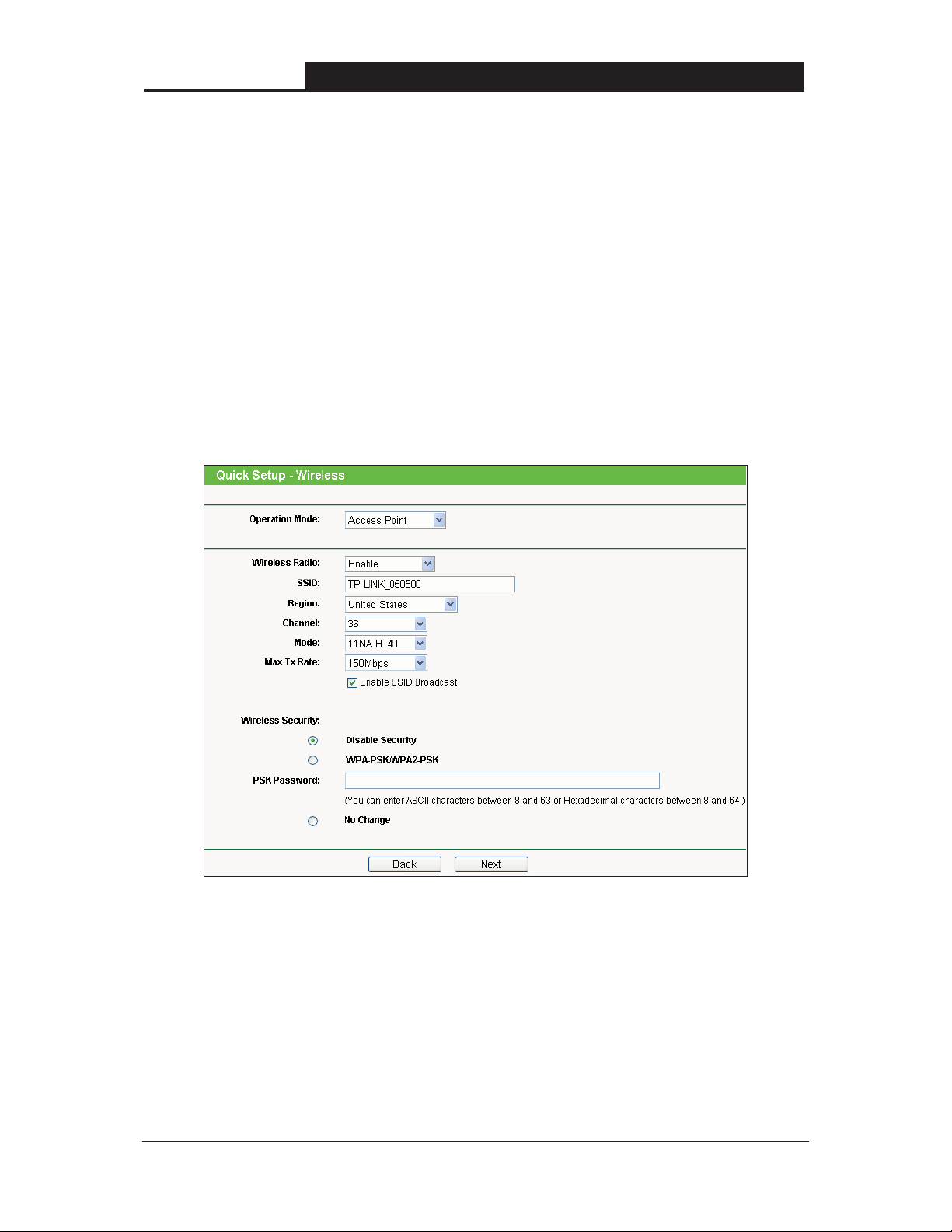
1. Click Next in Figure 3-10, and then Wireless page will appear as shown in Figure 3-
11.
Figure 3-11
¾ Operation Mode - Several Operation Modes are supported, including: Access Point,
Multi-SSID, Client, Repeater, Universal Repeater, and Bridge with AP. The available
setting options are different in various operation modes.
16
Page 26

TL-WA7510N 5GHz 150Mbps Indoor/ Outdoor Wireless Access Point User Guide
1) Access Point – This operation mode allows wireless stations to access.
Figure 3-12
z Wireless Radio- Enable or disable the wireless radio.
z SSID- Enter a string of up to 32 characters. The same Name (SSID) must be assigned to all
wireless devices in your network. The default SSID is set to be TP-LINK _xxxxxx (xxxxxx
indicates the last unique six characters of each AP's MAC address), which can ensure your
wireless network security. But it is recommended strongly that you change your networks
name (SSID) to a different value. This value is case-sensitive. For example, MYSSID is NOT
the same as MySsid.
z Region- Select your region from the pull-down list. This field specifies the region where the
wireless function of the Device can be used. It may be illegal to use the wireless function of
the Device in a region other than one of those specified in this filed. If your country or region
is not listed, please contact your local government agency for assistance.
z When you select your local region from the pull-down list, click the Save button, then the
Note Dialog appears. Click OK.
Note Dialog
17
Page 27

TL-WA7510N 5GHz 150Mbps Indoor/ Outdoor Wireless Access Point User Guide
z Channel- This field determines which operating frequency will be used. It is not necessary to
change the wireless channel unless you notice interference problems with another nearby
access point. If you select auto, then the AP will select the best channel automatically.
z Mode- This field determines the wireless mode which the AP works on.
z Max Tx Rate - You can limit the maximum tx rate of the AP through this field.
You can select one of the following security options:
z Disable Security- The wireless security function can be enabled or disabled. If disabled, the
wireless stations will be able to connect the AP without encryption. It is recommended
strongly that you choose one of the following options to enable security.
z WPA-PSK/WPA2-PSK- Select WPA based on pre-shared passphrase.
z PSK Password- You can enter ASCII or Hexadecimal characters.
For ASCII, the length should be between 8 and 63 characters.
For Hexadecimal, the length should be between 8 and 64 characters.
Please note that the key is case sensitive.
z Not Change- If you chose this option, wireless security configuration will not change.
2) Multi-SSID – AP can support up to 4 SSIDs.
Figure 3-13
18
Page 28

TL-WA7510N 5GHz 150Mbps Indoor/ Outdoor Wireless Access Point User Guide
z Wireless Radio- The wireless radio of the AP can be enabled or disabled to allow or deny
wireless stations to access. If enabled, the wireless stations will be able to access the AP;
otherwise, wireless stations will not be able to access the AP.
z Enable VLAN- Check this box to enable the VLAN function. The AP supports up to 4 VLANs.
All wireless PCs in the VLANs are able to access this AP. The AP can also work with an IEEE
802.1Q Tag VLAN supporting Switch. If this Switch enables the Tag VLAN function, besides
all wireless PCs, only the PCs in the VLAN same with SSID1 are able to access the AP. If a
PC is directly connected to the LAN port of the AP, please make sure that its adapter
supports Tag function, or this PC will not be able to access the AP.
z SSID- Enter a value of up to 32 characters. The same Name (SSID) must be assigned to all
wireless devices in your network. In Multi-SSID operation mode, enter SSID for each BSS in
the field "SSID1" ~ "SSID4".
z VLAN ID- The ID of a VLAN. Only in the same VLAN can a wireless PC and a wired PC
communicate with each other. The value can be between 1 and 4095. If the VLAN function is
enabled, when AP forwards packets, the packets out from the LAN port will be added with an
IEEE 802.1Q VLAN Tag, whose VLAN ID is just the ID of the VLAN where the sender
belongs.
z Region- Select your region from the pull-down list. This field specifies the region where the
wireless function of the AP can be used. It may be illegal to use the wireless function of the
AP in a region other than one of those specified in this filed. If your country or region is not
listed, please contact your local government agency for assistance.
When you select your local region from the pull-down list, click the Save button, then the
Note Dialog appears. Click OK.
Note Dialog
z Channel- This field determines which operating frequency will be used. It is not necessary to
change the wireless channel unless you notice interference problems with another nearby
access point.
z Mode-This field determines the wireless mode which the AP works on.
z Max Tx Rate- You can limit the maximum tx rate of the AP through this field.
z Enable SSID Broadcast- If you select the Enable SSID Broadcast checkbox, the AP will
broadcast its name (SSID) on the air.
You can select one of the following security options:
z Disable Security- The wireless security function can be enabled or disabled. If disabled, the
wireless stations will be able to connect the AP without encryption. It is recommended
strongly that you choose one of the following options to enable security.
z WPA-PSK/WPA2-PSK- Select WPA based on pre-shared passphrase.
19
Page 29

TL-WA7510N 5GHz 150Mbps Indoor/ Outdoor Wireless Access Point User Guide
z PSK Password- You can enter ASCII or Hexadecimal characters.
For ASCII, the length should be between 8 and 63 characters.
For Hexadecimal, the length should be between 8 and 64 characters.
Please note that the key is case sensitive.
z Not Change- If you chose this option, wireless security configuration will not change.
3) Client – The device will act as a wireless station to enable wired host(s) to access AP.
Figure 3-14
z Wireless Radio- The wireless radio of the AP can be enabled or disabled to allow or deny
wireless stations to access. If enabled, the wireless stations will be able to access the AP;
otherwise, wireless stations will not be able to access the AP.
z Enable WDS- The AP client can connect to AP with WDS enabled or disabled. If WDS is
enabled, all traffic from wired networks will be forwarded in the format of WDS frames
consisting of four address fields. If WDS is disabled, three address frames are used. If your
AP supports WDS well, please enable this option.
z SSID- Enter the SSID of AP that you want to access. If you select the radio button before
SSID, the AP client will connect to AP according to SSID.
z MAC of AP- Enter the MAC address of AP that you want to access. If you select the radio
button before MAC of AP, the AP client will connect to AP according to MAC address.
z Region- Select your region from the pull-down list. This field specifies the region where the
wireless function of the AP can be used. It may be illegal to use the wireless function of the
AP in a region other than one of those specified in this filed. If your country or region is not
listed, please contact your local government agency for assistance.
20
Page 30

TL-WA7510N 5GHz 150Mbps Indoor/ Outdoor Wireless Access Point User Guide
z When you select your local region from the pull-down list, click the Save button, then the
Note Dialog appears. Click OK.
Note Dialog
You can select one of the following security options:
z Disable Security- The wireless security function can be enabled or disabled. If disabled, the
wireless stations will be able to connect the AP without encryption. It is recommended
strongly that you choose one of the following options to enable security.
z WPA-PSK/WPA2-PSK- Select WPA based on pre-shared passphrase.
z PSK Password- You can enter ASCII or Hexadecimal characters.
For ASCII, the length should be between 8 and 63 characters.
For Hexadecimal, the length should be between 8 and 64 characters.
Please note that the key is case sensitive.
z Not Change- If you chose this option, wireless security configuration will not change.
4) Repeater
In Repeater mode, the AP with WDS enabled will relay data to an associated root AP. AP function
is enabled meanwhile. The wireless repeater relays signal between its stations and the root AP for
greater wireless range. Please input the MAC address of root AP in the field "MAC of AP".
Figure 3-15
21
Page 31

TL-WA7510N 5GHz 150Mbps Indoor/ Outdoor Wireless Access Point User Guide
z Wireless Radio- The wireless radio of the AP can be enabled or disabled to allow or deny
wireless stations to access. If enabled, the wireless stations will be able to access the AP;
otherwise, wireless stations will not be able to access the AP.
z MAC of AP- Enter the MAC address of AP that you want to access. If you select the radio
button before MAC of AP, the AP client will connect to AP according to MAC address.
z Region- Select your region from the pull-down list. This field specifies the region where the
wireless function of the AP can be used. It may be illegal to use the wireless function of the
AP in a region other than one of those specified in this filed. If your country or region is not
listed, please contact your local government agency for assistance.
When you select your local region from the pull-down list, click the Save button, then the
Note Dialog appears. Click OK.
Note Dialog
z Max Tx Rate- You can limit the maximum tx rate of the AP through this field.
You can select one of the following security options:
z Disable Security- The wireless security function can be enabled or disabled. If disabled, the
wireless stations will be able to connect the AP without encryption. It is recommended
strongly that you choose one of the following options to enable security.
z WPA-PSK/WPA2-PSK- Select WPA based on pre-shared passphrase.
z PSK Password- You can enter ASCII or Hexadecimal characters.
For ASCII, the length should be between 8 and 63 characters.
For Hexadecimal, the length should be between 8 and 64 characters.
Please note that the key is case sensitive.
z Not Change- If you chose this option, wireless security configuration will not change.
5) Universal Repeater
In Universal Repeater mode, the AP with WDS disabled will relay data to an associated root AP.
AP function is enabled meanwhile. The wireless repeater relays signal between its stations and
the root AP for greater wireless range. Please input the MAC address of root AP in the field "MAC
of AP".
22
Page 32

TL-WA7510N 5GHz 150Mbps Indoor/ Outdoor Wireless Access Point User Guide
Figure 3-16
z Wireless Radio- The wireless radio of the AP can be enabled or disabled to allow or deny
wireless stations to access. If enabled, the wireless stations will be able to access the AP;
otherwise, wireless stations will not be able to access the AP.
z MAC of AP- Enter the MAC address of AP that you want to access. If you select the radio
button before MAC of AP, the AP client will connect to AP according to MAC address.
z Region- Select your region from the pull-down list. This field specifies the region where the
wireless function of the AP can be used. It may be illegal to use the wireless function of the
AP in a region other than one of those specified in this filed. If your country or region is not
listed, please contact your local government agency for assistance.
When you select your local region from the pull-down list, click the Save button, then the
Note Dialog appears. Click OK.
Note Dialog
z Max Tx Rate- You can limit the maximum tx rate of the AP through this field.
You can select one of the following security options:
z Disable Security- The wireless security function can be enabled or disabled. If disabled, the
wireless stations will be able to connect the AP without encryption. It is recommended
strongly that you choose one of the following options to enable security.
z WPA-PSK/WPA2-PSK- Select WPA based on pre-shared passphrase.
23
Page 33

TL-WA7510N 5GHz 150Mbps Indoor/ Outdoor Wireless Access Point User Guide
z PSK Password- You can enter ASCII or Hexadecimal characters.
For ASCII, the length should be between 8 and 63 characters.
For Hexadecimal, the length should be between 8 and 64 characters.
Please note that the key is case sensitive.
z Not Change- If you chose this option, wireless security configuration will not change.
6) Bridge with AP
This operation mode bridges the AP and up to 4 APs also in bridge mode to connect two or more
wired LANs. Please input the MAC address of other APs in the field "MAC of AP1" to "MAC of
AP4". AP function will also start up.
Figure 3-17
z Wireless Radio- The wireless radio of the AP can be enabled or disabled to allow or deny
wireless stations to access. If enabled, the wireless stations will be able to access the AP;
otherwise, wireless stations will not be able to access the AP.
z SSID- Enter the SSID of AP that you want to access. If you select the radio button before
SSID, the AP client will connect to AP according to SSID.
z Region- Select your region from the pull-down list. This field specifies the region where the
wireless function of the AP can be used. It may be illegal to use the wireless function of the
24
Page 34

TL-WA7510N 5GHz 150Mbps Indoor/ Outdoor Wireless Access Point User Guide
AP in a region other than one of those specified in this filed. If your country or region is not
listed, please contact your local government agency for assistance.
z When you select your local region from the pull-down list, click the Save button, then the
Note Dialog appears. Click OK.
Note Dialog
z Channel- This field determines which operating frequency will be used. It is not necessary to
change the wireless channel unless you notice interference problems with another nearby
access point.
z Mode-This field determines the wireless mode which the AP works on.
z Max Tx Rate- You can limit the maximum tx rate of the AP through this field.
z Enable SSID Broadcast- If you select the Enable SSID Broadcast checkbox, the AP will
broadcast its name (SSID) on the air.
z MAC of AP- Enter the MAC address of AP that you want to access. If you select the radio
button before MAC of AP, the AP client will connect to AP according to MAC address.
You can select one of the following security options:
z Disable Security- The wireless security function can be enabled or disabled. If disabled, the
wireless stations will be able to connect the AP without encryption. It is recommended
strongly that you choose one of the following options to enable security.
z WPA-PSK/WPA2-PSK- Select WPA based on pre-shared passphrase.
z PSK Password- You can enter ASCII or Hexadecimal characters.
For ASCII, the length should be between 8 and 63 characters.
For Hexadecimal, the length should be between 8 and 64 characters.
Please note that the key is case sensitive.
z Not Change- If you chose this option, wireless security configuration will not change.
2. Click Finish button in Figure 3-18 to complete the Quick Setup.
Figure 3-18
25
Page 35

TL-WA7510N 5GHz 150Mbps Indoor/ Outdoor Wireless Access Point User Guide
3.2.2 AP Router Mode
When you choose AP Router Mode on Operation Mode page in Figure 3-10, take the following
steps:
1. Click Next in Figure 3-10, and then WAN Connection Ty
Figure 3-19.
Figure 3-19
¾ Auto Detect - If you don't know the connection type your ISP provides, use this option to
allow the Quick Setup to search your Internet connection for servers as well as protocols, and
to determine your ISP configuration. Make sure the cable is securely plugged into the WAN
port before detection. The appropriate configuration page will be displayed when an active
Internet service is successfully detected by the Device.
pe page will appear as shown in
If you choose Auto Detect in Figure 3-19 and then click Next, Figure 3-20 will appear.
Figure 3-20
¾ PPPoE - If you have applied ADSL to realize Dial-up service, you should choose this type. In
this condition, you should fill in both the User Name and Password that your ISP provides.
1) If you choose PPPoE in Figure 3-19 and then click Next, Figure 3-21 will appear.
26
Page 36

TL-WA7510N 5GHz 150Mbps Indoor/ Outdoor Wireless Access Point User Guide
Figure 3-21
2) Enter the User Name and Password provided by your ISP and then click Next, Figure 3-22
will appear.
Figure 3-22
z Wireless Radio- Enable or disable the wireless radio.
z SSID- Enter a string of up to 32 characters. The same Name (SSID) must be assigned to all
wireless devices in your network. The default SSID is set to be TP-LINK_xxxxxx (xxxxxx
indicates the last unique six characters of each Device's MAC address), which can ensure
your wireless network security. But it is recommended strongly that you change your
networks name (SSID) to a different value. This value is case-sensitive. For example,
MYSSID is NOT the same as MySsid.
z Region- Select your region from the pull-down list. This field specifies the region where the
wireless function of the Device can be used. It may be illegal to use the wireless function of
the Device in a region other than one of those specified in this filed. If your country or region
is not listed, please contact your local government agency for assistance.
z Channel- This field determines which operating frequency will be used. It is not necessary to
change the wireless channel unless you notice interference problems with another nearby
access point. If you select auto, then the Device will select the best channel
automatically.
27
Page 37

)
z Mode- This field determines the wireless mode which the Device works on.
z Max Tx Rate- You can limit the maximum tx rate of the Device through this field. You can
z Disable Security- The wireless security function can be enabled or disabled. If disabled, the
z WPA-PSK/WPA2-PSK- Select WPA based on pre-shared passphrase.
z PSK Password- You can enter ASCII or Hexadecimal characters.
z Not Change- If you chose this option, wireless security configuration will not change.
¾ Dynamic IP- When the Device connects to a DHCP server, or the ISP supplies you with
If you choose Dynamic IP in Figure 3-19 and then click Next, Figure 3-22 will appear.
TL-WA7510N 5GHz 150Mbps Indoor/ Outdoor Wireless Access Point User Guide
select one of security options listed as the below items.
wireless stations will be able to connect the Device without encryption. It is recommended
strongly that you choose one of the following options to enable security.
For ASCII, the length should be between 8 and 63 characters.
For Hexadecimal, the length should be between 8 and 64 characters.
Please note that the key is case sensitive.
DHCP connection, please choose this type. The Device will get the IP address automatically
from the DHCP server or the ISP if you choose the Dynamic IP type.
type,
¾ Static IP - In this
Gateway, and DNS IP address, which are specified by your ISP.
1) If you choose Static IP in Figure 3-19 and then click Next, Figure 3-23 will appear.
z IP Address- This is WAN IP address as seen by external users on the Internet (including
your ISP). Enter the IP address in the field.
z Subnet Mask- It is used for the WAN IP address, which is usually 255.255.255.0.
z Default Gateway- Enter the default gateway in the blank if required.
you should manually fill in the IP address, Subnet Mask, Default
Figure 3-23
z Primary DNS- Enter the DNS IP address in the blank if required.
z Secondary DNS- If your ISP provides another DNS IP address, enter it in this field.
Note:
The IP parameters should have been provided by your ISP.
28
Page 38

2) After you have entered the above necessary parameters and then click Next, Figure 3-22 will
2. When you finish the wireless setting in Figure 3-22 and click Next, then Figure 3-24 will
TL-WA7510N 5GHz 150Mbps Indoor/ Outdoor Wireless Access Point User Guide
then appear.
appear, wher
e you can click Finish button to complete the Quick Setup.
Figure 3-24
3.2.3 AP Client Router Mode
When you choose AP Client Router Mode on Operation Mode page in Figure 3-10, take the
following steps:
1. Click Next in Figure 3-10, and then WAN Connection Ty
Figure 3-25.
Figure 3-25
¾ PPPoE - If you have applied ADSL to realize Dial-up service, you should choose this type. In
this condition, you should fill in both the User Name and Password that your ISP supplies.
1) If you choose PPPoE in Figure 3-25 and then click Next, Figure 3-26 will appear.
pe page will appear as shown in
29
Page 39

TL-WA7510N 5GHz 150Mbps Indoor/ Outdoor Wireless Access Point User Guide
Figure 3-26
2) Enter the User Name and Password provided by your ISP, then click Next, Figure 3-27
will appear.
Figure 3-27
z SSID - The SSID of the AP your Device is going to connect to as a client. You can also use
the search function to select the SSID to join.
z BSSID - The BSSID of the AP your Device is going to connect to as a client. You can also
use the search function to select the BSSID to join.
z Region - Select your region from the pull-down list. This field specifies the region where the
wireless function of the Device can be used. It may be illegal to use the wireless function of
the Device in a region other than one of those specified in this filed. If your country or region
is not listed, please contact your local government agency for assistance.
z Search - Click this button, you can search the AP which runs in the current channel.
z Key type - This option should be chosen according to the AP's security configuration. It is
recommended that the security type is the same as your AP's security type.
z WEP Index - This option should be chosen if the key type is WEP (ASCII) or WEP (HEX).It
indicates the index of the WEP key.
z Auth Type - This option should be chosen if the key type is WEP (ASCII) or WEP (HEX).It
indicates the authorization type of the Root AP.
30
Page 40

)
¾ Dynamic IP- When the Device connects to a DHCP server, or the ISP supplies you with
¾ Static IP - In this type, you should manually fill in the IP address, Subnet Mask, Default
1) If you choose Static IP in Figure 3-25 and then click Next, Figure 3-28 will appear.
TL-WA7510N 5GHz 150Mbps Indoor/ Outdoor Wireless Access Point User Guide
z Password - If the AP your Device is going to connect needs password, you need to fill the
password in this blank.
DHCP connection, please choose this type. The Device will get the IP address automatically
from the DHCP server or the WISP if you choose the Dynamic IP type.
If you choose Dynamic IP in Figure 3-25 and then click Next, the wire
Figure 3-27 will appear.
Gateway, and DNS IP address, which are specified by your ISP.
less setting page as in
Figure 3-28
z IP Address- This is WAN IP address as seen by external users on the Internet (including
your ISP). Enter the IP address into the field.
z Subnet Mask- It is used for the WAN IP address, which is usually 255.255.255.0.
z Default Gateway- Enter the default gateway in the blank if required.
z Primary DNS- Enter the DNS IP address in the blank if required.
z Secondary DNS- If your WISP provides another DNS IP address, enter it in this field.
Note:
The IP parameters should have been provided by your WISP.
2) After you have entered the above necessary parameters and then click Next, the wireless
setting page as in Figure 3-27 will then appear.
When you finish the wireless
2.
appear, wher
e you can click Finish button to complete the Quick Setup.
setting in Figure 3-27 and click Next, then Figure 3-29 will
Figure 3-29
31
Page 41

)
TL-WA7510N 5GHz 150Mbps Indoor/ Outdoor Wireless Access Point User Guide
Chapter 4 Configuring Standard AP Mode
This chapter will show each Web page's key functions and the configuration way under Standard
AP Mode.
4.1 Login
Open your web browser. Type in the default address http://192.168.1.254 in the address field of
web browser and then press Enter.
Figure 4-1 Login to the AP
Enter admin for the User Name and Password (both in lower case letters) in Figure 4-2 below.
Then click OK or press Enter.
Figure 4-2 Login Windows
Note:
If the above screen does not prompt, it means that your web-browser has been set to a proxy. Go
to Tools menu>Internet Options>Connections>LAN Settings, in the screen that appears,
cancel the Using Proxy checkbox, and click OK to finish it.
After a successful login, you can configure and manage the Device. There are eight main menus
on the leftmost column of the web-based management page as in Figure 4-3: Status, Quick
Setup, QSS, Operation Mode, Netw
be available after clicking one of the main menus. On the right of the web-based management
page lays the detailed explanations and instructions for the corresponding page.
ork, Wireless, DHCP and System Tools. Sub-menus will
32
Page 42

Figure 4-3 the main menu
TL-WA7510N 5GHz 150Mbps Indoor/ Outdoor Wireless Access Point User Guide
4.2 Status
Selecting Status will enable you to view the AP’s current status and configuration, all of which are
read-only.
Figure 4-4 Status
33
Page 43

)
¾ Firmware Version - The current firmware version of the AP.
¾ Hardware Version - The current hardware version of the AP.
¾ LAN - The following is the information of wired LAN. You can configure them in the Network
¾ Wireless - These are the current settings or information for wireless. You can configure them
TL-WA7510N 5GHz 150Mbps Indoor/ Outdoor Wireless Access Point User Guide
page.
z MAC Address - The physical address of the system, as seen from the LAN.
z IP Address - The IP address of the wired LAN.
z Subnet Mask - The subnet mask associated with IP address.
in the Wireless -> Wireless Settings page.
z Wireless AP Mode - The current wireless AP mode which the AP works on.
z Name (SSID) - The SSID of the AP.
z Channel - The current wireless channel in use.
z Mode - The current wireless mode which the AP works on.
z Max Tx Rate - The maximum tx rate.
z MAC Address - The physical address of the AP, as seen from the WLAN.
¾ Traffic Statistics - The system traffic statistics.
z Sent (Bytes) - Traffic that counted in bytes has been sent out from WLAN.
z Sent (Packets) - Traffic that counted in packets has been sent out from WLAN.
z Received (Bytes) - Traffic that counted in bytes has been received from WLAN.
z Received (Packets) - Traffic that counted in packets has been received from WLAN.
¾ System Up Time - The length of the time since the AP was last powered on or reset.
Click the Refresh button to get the latest status and settings of the AP.
4.3 Quick Setup
Please refer to Section 3.2 Quick Setup – 3.2.1 Standard AP Mode for more details.
4.4 QSS
QSS (Quick Secure Setup) can help you to quickly and securely connect to a network. This
section will guide you to add a new wireless device to an existing network quickly by function.
Note:
The QSS function is only available when the Operation Mode is set to Access Point and
Multi-SSID. Here we take the Access Point mode for example.
34
Page 44

)
)
Select menu QSS, you will see the next screen as shown in Figure 4-5.
¾ QSS Status - Enable or disable the QSS function here.
¾ Current PIN - The current value of the Device's PIN displayed here. The default PIN of the
¾ Restore PIN - Restore the PIN of the Device to its default.
TL-WA7510N 5GHz 150Mbps Indoor/ Outdoor Wireless Access Point User Guide
Figure 4-5 QSS
Device can be found in the label or User Guide.
¾ Gen New PIN - Click this button, and then you can get a new random value for the Device's
PIN. You can ensure the network security by generating a new PIN.
¾ Add A New Device - You can add the new device to the existing network manually by
clicking Add Device button.
Note:
The QSS function cannot be configured if the Wireless Function of the Device is disabled. Please
make sure the Wireless Function is enabled before configuring the QSS.
¾ To add a new device:
1. If the new device supports Wi-Fi Protected Setup and is equipped with a configuration button,
you can add it to the network by pressing the configuration button on the device.
2. If the new device supports Wi-Fi Protected Setup and the connection way using PIN, you can
add it to the network by entering the Device's PIN.
Note:
To build a successful connection by QSS, you should also do the corresponding configuration on a
wireless adapter for QSS function meanwhile.
For the configuration of the new device, here takes the Wireless Adapter of our company for
example.
35
Page 45

TL-WA7510N 5GHz 150Mbps Indoor/ Outdoor Wireless Access Point User Guide
I. By PBC
Step 1: Keep the default QSS Status as Enabled and click the Add device button in Figure 4-5,
and then the following screen will appear.
Figure 4-6 Add A New Device
Step 2: Choose “Press the button of the new device in two minutes” and click Connect.
Step 3: Configure the wireless adapter for QSS function by choosing “Push the button on my
access point” in the QSS configuration utility as below, and then click Next.
Figure 4-7 The QSS Configuration Screen of Wireless Adapter
Step 4: Wait for a while until the next screen appears. Click Finish to complete the QSS
configuration.
36
Page 46

)
TL-WA7510N 5GHz 150Mbps Indoor/ Outdoor Wireless Access Point User Guide
Figure 4-8 The QSS Configuration Screen of Wireless Adapter
II. By PIN
If the device supports Wi-Fi Protected Setup and the PIN method, you can add it to the network by
PIN in the following two methods.
Method One: Enter the PIN into my AP
Step 1: Keep the default QSS Status as Enabled and click the Add device button in Figure 4-5,
and then the following screen will appear.
Figure 4-9 Add A New Device
Step 2: Choose “Enter the new device's PIN” and enter the PIN code˄take 16952898 for
example˅ of the wireless adapter in the field after PIN as shown in the figure above. Then
click Connect.
Note:
The PIN code of the adapter is always displayed on the QSS configuration screen as shown in
Figure 4-10.
37
Page 47

)
Step 3: Configure the wireless adapter for QSS function by choosing “Enter a PIN into my
access point or a registrar” in the configuration utility of the QSS as below, and click
Next.
TL-WA7510N 5GHz 150Mbps Indoor/ Outdoor Wireless Access Point User Guide
Figure 4-10 The QSS Configuration Screen of Wireless Adapter
Note:
In this example, the default PIN code of this adapter is 16952898 as the above figure shown.
Method Two: Enter the PIN from my AP
Step 1: Get the Current PIN code of the AP in Figure 4-11 (Each AP has its unique PIN code.
Step 2: Configure the wireless adapter for QSS function by choosing “Enter a PIN from my
access point” in the configuration utility of the QSS as below, and enter the PIN code of
the AP into the field after “Access Point PIN”. Then click Next.
Here takes the default PIN code 1234
5670 of this AP for example).
38
Page 48

)
)
TL-WA7510N 5GHz 150Mbps Indoor/ Outdoor Wireless Access Point User Guide
Figure 4-11 The QSS Configuration Screen of Wireless Adapter
Note:
Note:
ccessfully connected to the network.
Figure 4-12
The default PIN code of the AP can be found in its label or the QSS configuration screen as in
Figure 4-5.
You will see the following screen when the new device has su
The QSS function cannot be configured if the Wireless function of the AP is disabled. Please
make sure the Wireless function is enabled before configuring the QSS.
39
Page 49

)
TL-WA7510N 5GHz 150Mbps Indoor/ Outdoor Wireless Access Point User Guide
4.5 Operation Mode
Figure 4-13
¾ Standard AP: In this mode, the device enables multi-users to access, and provides several
wireless modes, such as AP, Client, Repeater and so on.
¾ AP Router: In this mode, the device enables multi-users to share Internet via ADSL/Cable
Modem. The wireless port share the same IP to ISP through Ethernet WAN port. The
Wireless port acts the same as a LAN port while at AP Router mode.
¾ AP Client Router: In this mode, the device enables multi-users to share Internet from WISP.
The LAN port devices share the same IP from WISP through Wireless port. While connecting
to WISP, the Wireless port works as a WAN port at AP Client Router mode. The Ethernet port
acts as a LAN port.
Be sure to click the Save button to save your settings on this page.
Note:
The Device will reboot automatically after you click the Save button.
4.6 Network
The Network option allows you to customize your local network manually by changing the default
settings of the AP.
Figure 4-14 The Network menu
Selecting Network > LAN will enable you to configure the IP parameters of LAN on the following
page.
40
Page 50

)
)
¾ MAC Address- The physical address of the LAN ports, as seen from the LAN. The value can
¾ Type- Choosing dynamic IP to get IP address from DHCP server, or choosing static IP to
¾ IP Address- Enter the IP address of your system in dotted-decimal notation (factory default:
TL-WA7510N 5GHz 150Mbps Indoor/ Outdoor Wireless Access Point User Guide
Figure 4-15 LAN
not be changed.
configure IP address manually.
192.168.1.254).
¾ Subnet Mask- It is an address code that determines the size of the network. Normally
255.255.255.0 is used as the subnet mask.
¾ Gateway- The gateway should be in the same subnet as your IP address.
Note:
1. If you change the IP address, you must use the new IP address to login the system.
2. If you select the type of dynamic IP, the DHCP server in this device will not start up.
3. If the new IP address you set is not in the same subnet, the IP Address pool in the DHCP
server will not take effect, until they are re-configured.
4. The device will reboot automatically after you click the Save button.
Click the Save button to save your settings.
Note:
When you choose the Dynamic IP mode, the DHCP Server function will be disabled.
4.7 Wireless
The Wireless option improves functionality and performance for wireless network. It can help you
make the AP an ideal solution for your wireless network. There are eight submenus under the
Wireless menu (shown in Figure 4-16): Wireless Settings, Wireless Securit
41
y, Wirel
ess MAC
Page 51

Filtering, Wireless Advanced, Antenna Alignment, Distance Settings, Throughput Monitor
and Wireless Statistics.
TL-WA7510N 5GHz 150Mbps Indoor/ Outdoor Wireless Access Point User Guide
Figure 4-16 Wireless menu
Click any of them, and you will be able to configure the corresponding function. The detailed
explanations for each submenu are provided below.
4.7.1 Wireless Settings
Selecting Wireless > Wireless Settings will enable you to configure the basic settings for your
wireless network. The setting page allows you to configure the wireless mode for your device. Six
operation modes are supported here, including Access Point, Multi-SSID, Client, Repeater,
Universal Repeater and Bridge with AP.
Please refer to Section 3.2 Quick Setup – 3.2.1 Standard AP Mode
for more details.
4.7.2 Wireless Security
Selecting Wireless > Wireless Security will enable you to configure wireless security for your
wireless network to protect your data from intruders. The AP provides three security types: WEP,
WPA/WPA2 and WPA-PSK/WPA2-PSK. Wireless security can be set on the following screen
shown as Figure 4-17. The security options are different for different ope
on mode.
rati
42
Page 52

TL-WA7510N 5GHz 150Mbps Indoor/ Outdoor Wireless Access Point User Guide
1) Access Point
Figure 4-17 Wireless Security - Access Point
¾ Operation Mode - Shows the current operation mode.
¾ Disable Security - The wireless security function can be enabled or disabled. If disabled, the
wireless stations will be able to connect the AP without encryption. It is recommended
strongly that you choose one of the following options to enable security.
¾ WEP - Select 802.11 WEP security.
¾ WPA-PSK - Select WPA based on pre-shared passphrase.
¾ WPA - Select WPA based on Radius Server.
Each security option has its own settings as described follows:
¾ WEP
z Type - You can select one of following types:
Automatic - Select Shared Key or Open System authentication type automatically based on
the wireless station's capability and request.
43
Page 53

)
z WEP Key Format - You can select ASCII or Hexadecimal format. ASCII Format stands for
z WEP Key settings - Select which of the four keys will be used and enter the matching WEP
z Key Type - You can select the WEP key length (64-bit, or 128-bit, or 152-bit.) for encryption.
TL-WA7510N 5GHz 150Mbps Indoor/ Outdoor Wireless Access Point User Guide
Shared Key - Select 802.11 Shared Key authentications.
Open System - Select 802.11 Open System authentication.
any combination of keyboard characters in the specified length. Hexadecimal format stands
for any combination of hexadecimal digits (0-9, a-f, A-F) in the specified length.
key information for your network in the selected key radio button. These values must be
identical on all wireless stations in your network.
"Disabled" means this WEP key entry is invalid.
For 64-bit encryption - You can enter 10 hexadecimal digits (any combination of 0-9, a-f,
A-F, and null key is not permitted) or 5 ASCII characters.
For 128-bit encryption - You can enter 26 hexadecimal digits (any combination of 0-9, a-f,
A-F, and null key is not permitted) or 13 ASCII characters.
For 152-bit encryption - You can enter 32 hexadecimal digits (any combination of 0-9, a-f,
A-F, and null key is not permitted) or 16 ASCII characters.
Note:
If you do not set the key, the wireless security function is still disabled even if you have selected
Shared Key as Authentication Type.
¾ WPA/WPA2
z Version - You can select one of following versions:
Automatic - Select WPA or WPA2 automatically based on the wireless station's capability
and request.
WPA - Wi-Fi Protected Access.
WPA2 - WPA version 2.
z Encryption - You can select either Automatic, or TKIP or AES.
z Radius Server IP - Enter the IP address of the Radius Server.
z Radius Port - Enter the port that radius service uses.
z Radius Password - Enter the password for the Radius Server.
z Group Key Update Period - Specify the group key update interval in seconds. The value can
be either 0 or at least 30. Enter 0 to disable the update.
44
Page 54

TL-WA7510N 5GHz 150Mbps Indoor/ Outdoor Wireless Access Point User Guide
¾ WPA-PSK/WPA2-PSK
z Version - You can select one of following versions:
Automatic - Select WPA-PSK or WPA2-PSK automatically based on the wireless station's
capability and request.
WPA-PSK - Pre-shared key of WPA.
WPA2-PSK - Pre-shared key of WPA2.
z Encryption - You can select either Automatic, or TKIP or AES.
z PSK Password - You can enter ASCII or Hexadecimal characters. For Hexadecimal, the
length should be between 8 and 64 characters; for ASCII, the length should be between 8 and
63 characters.
z Group Key Update Period - Specify the group key update interval in seconds. The value can
be either 0 or at least 30. Enter 0 to disable the update.
2) Multi-SSID
Figure 4-18 Wireless Security – Multi-SSID
¾ Operation Mode - Shows the current operation mode. You can choose one of the 4 SSID
from the pull-down list.
45
Page 55

)
)
¾ Disable Security - Check this box radio button to disable wireless security. If disabled, the
¾ WPA/WPA2 - Select WPA/WPA2 based on Radius Server.
z Version - You can select one of following versions.
z Encryption - You can select Automatic, TKIP or AES.
z Radius Server IP - Enter the IP address of the Radius Server.
z Radius Port - Enter the port used by radius service.
z Radius Password - Enter the password for the Radius Server.
z Group Key Update Period - Specify the group key update interval in seconds. The value can
TL-WA7510N 5GHz 150Mbps Indoor/ Outdoor Wireless Access Point User Guide
wireless stations will be able to connect this device without encryption. It is strongly
recommended that you choose one of the security types to enable security.
Automatic - Select WPA or WPA2 automatically based on the wireless station's capability
and request.
WPA - Wi-Fi Protected Access.
WPA2 - WPA version 2.
be either 0 or at least 30. Enter 0 to disable the update.
Note:
This security option will become unavailable, if the Enable VLAN box in Figure 3-13 is checked.
¾ WPA-PSK/ WPA2-PSK - Select WPA based on pre-shared key.
z Version - You can select one of following versions.
Automatic - Select WPA-PSK or WPA2-PSK automatically based on the wireless station's
capability and request.
WPA-PSK - Pre-shared key of WPA.
WPA2-PSK - Pre-shared key of WPA2.
z Encryption - When you select WPA-PSK or WPA2-PSK for Authentication Type, you can
select Automatic, TKIP or AES as Encryption.
z PSK Passphrase - Enter a passphrase here.
z Group Key Update Period - Specify the group key update interval in seconds. The value can
be either 0 or at least 30. Enter 0 to disable the update.
Be sure to click the Save button to save your settings on this page.
Note:
You will be reminded to reboot the device after clicking the Save button.
46
Page 56

TL-WA7510N 5GHz 150Mbps Indoor/ Outdoor Wireless Access Point User Guide
3) Client
Figure 4-19 Wireless Security – Client
¾ Operation Mode - Shows the current operation mode.
¾ Disable Security - Check this box radio button to disable wireless security. If disabled, the
wireless stations will be able to connect this device without encryption. It is strongly
recommended that you choose one of the security types to enable security.
¾ WEP - Select 802.11 WEP security.
z Type - You can select one of following types.
Automatic - Select Shared Key or Open System authentication type automatically based
on the wireless station's capability and request.
Shared Key - Select 802.11 Shared Key authentication type.
Open System - Select 802.11 Open System authentication.
z WEP Key Format - You can select ASCII or Hexadecimal format. ASCII format stands for
any combination of keyboard characters in the specified length. Hexadecimal format stands
for any combination of hexadecimal digits (0-9, a-f, A-F) in the specified length.
z WEP Key - Select which of the four keys will be used and enter the matching WEP key
information for your network in the selected key radio button. These values must be identical
on all wireless stations in your network.
z Key Type - You can select the WEP key length (64-bit, or 128-bit, or 152-bit.) for encryption.
"Disabled" means this WEP key entry is invalid.
47
Page 57

)
)
If you do not set the key, the wireless security function is still disabled even if you have selected
Shared Key as Authentication Type.
¾ WPA-PSK/ WPA2-PSK - Select WPA based on pre-shared key.
z Version - You can select one of following versions.
TL-WA7510N 5GHz 150Mbps Indoor/ Outdoor Wireless Access Point User Guide
For 64-bit encryption - You can enter 10 hexadecimal digits (any combination of 0-9, a-f, A-F,
zero key is not permitted) or 5 ASCII characters.
For 128-bit encryption - You can enter 26 hexadecimal digits (any combination of 0-9, a-f, A-F,
zero key is not permitted) or 13 ASCII characters.
For 152-bit encryption - You can enter 32 hexadecimal digits (any combination of 0-9, a-f, A-F,
zero key is not permitted) or 16 ASCII characters.
Note:
Automatic - Select WPA-PSK or WPA2-PSK automatically based on the wireless station's
capability and request.
WPA-PSK - Pre-shared key of WPA.
WPA2-PSK - Pre-shared key of WPA2.
z Encryption - When you select WPA-PSK or WPA2-PSK for Authentication Type, you can
select Automatic, TKIP or AES as Encryption.
z PSK Passphrase - Enter a passphrase here.
z Group Key Update Period - Specify the group key update interval in seconds. The value can
be either 0 or at least 30. Enter 0 to disable the update.
Be sure to click the Save button to save your settings on this page.
Note:
You will be reminded to reboot the device after clicking the Save button.
48
Page 58

TL-WA7510N 5GHz 150Mbps Indoor/ Outdoor Wireless Access Point User Guide
4) Repeater
Figure 4-20 Wireless Security – Repeater
¾ Operation Mode - Shows the current operation mode.
¾ Disable Security - Check this box radio button to disable wireless security. If disabled, the
wireless stations will be able to connect this device without encryption. It is strongly
recommended that you choose one of the security types to enable security.
¾ WEP - Select 802.11 WEP security.
z Type - You can select one of following types.
Automatic - Select Shared Key or Open System authentication type automatically based on
the wireless station's capability and request.
Shared Key - Select 802.11 Shared Key authentication type.
Open System - Select 802.11 Open System authentication.
z WEP Key Format - You can select ASCII or Hexadecimal format. ASCII format stands for
any combination of keyboard characters in the specified length. Hexadecimal format stands
for any combination of hexadecimal digits (0-9, a-f, A-F) in the specified length.
z WEP Key - Select which of the four keys will be used and enter the matching WEP key
information for your network in the selected key radio button. These values must be identical
on all wireless stations in your network.
z Key Type - You can select the WEP key length (64-bit, or 128-bit, or 152-bit.) for encryption.
"Disabled" means this WEP key entry is invalid.
49
Page 59

)
)
If you do not set the key, the wireless security function is still disabled even if you have selected
Shared Key as Authentication Type.
¾ WPA-PSK/ WPA2-PSK - Select WPA based on pre-shared key.
z Version - You can select one of following versions.
TL-WA7510N 5GHz 150Mbps Indoor/ Outdoor Wireless Access Point User Guide
For 64-bit encryption - You can enter 10 hexadecimal digits (any combination of 0-9, a-f, A-F,
zero key is not permitted) or 5 ASCII characters.
For 128-bit encryption - You can enter 26 hexadecimal digits (any combination of 0-9, a-f, A-F,
zero key is not permitted) or 13 ASCII characters.
For 152-bit encryption - You can enter 32 hexadecimal digits (any combination of 0-9, a-f, A-F,
zero key is not permitted) or 16 ASCII characters.
Note:
Automatic - Select WPA-PSK or WPA2-PSK automatically based on the wireless station's
capability and request.
WPA-PSK - Pre-shared key of WPA.
WPA2-PSK - Pre-shared key of WPA2.
z Encryption - When you select WPA-PSK or WPA2-PSK for Authentication Type, you can
select Automatic, TKIP or AES as Encryption.
z PSK Passphrase - Enter a passphrase here.
z Group Key Update Period - Specify the group key update interval in seconds. The value can
be either 0 or at least 30. Enter 0 to disable the update.
Be sure to click the Save button to save your settings on this page.
Note:
You will be reminded to reboot the device after clicking the Save button.
50
Page 60

TL-WA7510N 5GHz 150Mbps Indoor/ Outdoor Wireless Access Point User Guide
5) Universal Repeater
Figure 4-21 Wireless Security – Universal Repeater
¾ Operation Mode - Shows the current operation mode.
¾ Disable Security - Check this box radio button to disable wireless security. If disabled, the
wireless stations will be able to connect this device without encryption. It is strongly
recommended that you choose one of the security types to enable security.
¾ WEP - Select 802.11 WEP security.
z Type - You can select one of following types.
Automatic - Select Shared Key or Open System authentication type automatically based on
the wireless station's capability and request.
Shared Key - Select 802.11 Shared Key authentication type.
Open System - Select 802.11 Open System authentication.
z WEP Key Format - You can select ASCII or Hexadecimal format. ASCII format stands for
any combination of keyboard characters in the specified length. Hexadecimal format stands
for any combination of hexadecimal digits (0-9, a-f, A-F) in the specified length.
z WEP Key - Select which of the four keys will be used and enter the matching WEP key
information for your network in the selected key radio button. These values must be identical
on all wireless stations in your network.
51
Page 61

)
)
z Key Type - You can select the WEP key length (64-bit, or 128-bit, or 152-bit.) for encryption.
If you do not set the key, the wireless security function is still disabled even if you have selected
Shared Key as Authentication Type.
¾ WPA-PSK/ WPA2-PSK - Select WPA based on pre-shared key.
z Version - You can select one of following versions.
TL-WA7510N 5GHz 150Mbps Indoor/ Outdoor Wireless Access Point User Guide
"Disabled" means this WEP key entry is invalid.
For 64-bit encryption - You can enter 10 hexadecimal digits (any combination of 0-9, a-f, A-F,
zero key is not permitted) or 5 ASCII characters.
For 128-bit encryption - You can enter 26 hexadecimal digits (any combination of 0-9, a-f, A-F,
zero key is not permitted) or 13 ASCII characters.
For 152-bit encryption - You can enter 32 hexadecimal digits (any combination of 0-9, a-f, A-F,
zero key is not permitted) or 16 ASCII characters.
Note:
Automatic - Select WPA-PSK or WPA2-PSK automatically based on the wireless station's
capability and request.
WPA-PSK - Pre-shared key of WPA.
WPA2-PSK - Pre-shared key of WPA2.
z Encryption - When you select WPA-PSK or WPA2-PSK for Authentication Type, you can
select Automatic, TKIP or AES as Encryption.
z PSK Passphrase - Enter a passphrase here.
z Group Key Update Period - Specify the group key update interval in seconds. The value can
be either 0 or at least 30. Enter 0 to disable the update.
Be sure to click the Save button to save your settings on this page.
Note:
You will be reminded to reboot the device after clicking the Save button.
52
Page 62

TL-WA7510N 5GHz 150Mbps Indoor/ Outdoor Wireless Access Point User Guide
Figure 4-22 Wireless Security – Bridge with AP
¾ Operation Mode - Shows the current operation mode.
¾ Disable Security - Check this box radio button to disable wireless security. If disabled, the
wireless stations will be able to connect this device without encryption. It is strongly
recommended that you choose one of the security types to enable security.
¾ WEP - Select 802.11 WEP security.
z Type - You can select one of following types.
Automatic - Select Shared Key or Open System authentication type automatically based
on the wireless station's capability and request.
Shared Key - Select 802.11 Shared Key authentication type.
Open System - Select 802.11 Open System authentication.
z WEP Key Format - You can select ASCII or Hexadecimal format. ASCII format stands for
any combination of keyboard characters in the specified length. Hexadecimal format stands
for any combination of hexadecimal digits (0-9, a-f, A-F) in the specified length.
z WEP Key - Select which of the four keys will be used and enter the matching WEP key
information for your network in the selected key radio button. These values must be identical
on all wireless stations in your network.
z Key Type - You can select the WEP key length (64-bit, or 128-bit, or 152-bit.) for encryption.
"Disabled" means this WEP key entry is invalid.
53
Page 63

)
)
1. If you do not set the key, the wireless security function is still disabled even if you have
2. You will be reminded to reboot the device after clicking the Save button.
TL-WA7510N 5GHz 150Mbps Indoor/ Outdoor Wireless Access Point User Guide
For 64-bit encryption - You can enter 10 hexadecimal digits (any combination of 0-9, a-f, A-F,
zero key is not permitted) or 5 ASCII characters.
For 128-bit encryption - You can enter 26 hexadecimal digits (any combination of 0-9, a-f,
A-F, zero key is not permitted) or 13 ASCII characters.
For 152-bit encryption - You can enter 32 hexadecimal digits (any combination of 0-9, a-f,
A-F, zero key is not permitted) or 16 ASCII characters.
Note:
selected Shared Key as Authentication Type.
4.7.3 Wireless MAC Filtering
Selecting Wireless > Wireless MAC Filtering will allow you to set up some filtering rules to
control wireless stations accessing the device, which depend on the station’s MAC address on the
following screen as shown in Figure 4-23. As the configuration is the same in each oper
here we just take the Access Point for example.
ation mode,
Note:
This function is not available when the operation is set to Client.
Figure 4-23 Wireless MAC address Filtering
¾ Operation Mode - Shows the current operation mode.
54
Page 64

TL-WA7510N 5GHz 150Mbps Indoor/ Outdoor Wireless Access Point User Guide
¾ Wireless MAC Filtering - Click the Enable button to enable the Wireless MAC Address
Filtering. The default setting is disabled.
¾ To Add a Wireless MAC Address filtering entry, click the Add New… button. The “Add or
Modify Wireless MAC Address Filtering entry" page will appear, shown in Figure 4-24.
Figure 4-24 Add or Modify Wireless MAC Address Filtering entry
z MAC Address - Enter the wireless station's MAC address that you want to control.
z Description - Give a simple description of the wireless station.
z Status - Select a status for this entry, either Enabled or Disabled.
¾ To set up an entry, click Enable, and follow these instructions:
1. First, you must decide whether the unspecified wireless stations can or cannot access the AP;
2. If you desire that the unspecified wireless stations can access the AP, please select the radio
button Allow the stations not specified by any enabled entries in the list to access;
3. Otherwise, select the radio button Deny the stations not specified by any enabled entries
in the list to access.
¾ To Add a Wireless MAC Address filtering entry, clicking the Add New... button, and following
these instructions:
1. Enter the appropriate MAC Address into the MAC Address field. The format of the MAC
Address is XX-XX-XX-XX-XX-XX (X is any hexadecimal digit). For example,
00-0A-EB-B0-00-0B.
2. Enter a simple description of the wireless station in the Description field. For example,
Wireless station A.
3. Status - Select Enabled or Disabled for this entry on the Status pull-down list.
4. Click the Save button to save this entry.
¾ To add another entries, repeat steps 1~4.
55
Page 65

)
¾ To modify or delete an existing entry:
1. Click the Modify in the entry you want to modify. If you want to delete the entry, click the
2. Modify the information.
3. Click the Save button.
Click the Enable All button to make all the Entries enabled.
Click the Disable All button to make all the Entries disabled.
Click the Delete All button to delete all the entries.
Click the Next button to go to the next page.
Click the Previous button to return to the previous page.
1. If you enable the function and select the Deny the stations not specified by any enabled
2. Only in Standard AP mode, the current operation mode is shown at the top. Besides, if
TL-WA7510N 5GHz 150Mbps Indoor/ Outdoor Wireless Access Point User Guide
Delete.
Note:
entries in the list to access for Filtering Rules, there will be not any enable entries in the list;
thus, no wireless stations can access the AP.
Multi-SSID, a sub mode of Standard AP, is selected, you can choose one of the 4 SSIDs from
the pull-down list.
4.7.4 Wireless Advanced
Selecting Wireless > Wireless Advanced will allow you to do some advanced settings for the
device in the following screen as shown in Figure 4-25. As the configuration for each operation
mode is almost the same, we take Access Point mode for example here.
56
Page 66

)
¾ Antenna Settings - The polarization of an antenna. You can select Vertical Antenna,
¾ Transmit Power - Here you can specify the transmit power of the Device. You can select
TL-WA7510N 5GHz 150Mbps Indoor/ Outdoor Wireless Access Point User Guide
Figure 4-25 Wireless Advanced
Horizontal Antenna or External Antenna.
High, Middle or Low whichever you would like. High is the default setting and is
recommended.
¾ Beacon Interval - The beacons are the packets sent by the Device to synchronize a wireless
network. Beacon Interval value determines the time interval of the beacons. You can specify
a value between 20-1000 milliseconds. The default value is 100.
¾ RTS Threshold - Here you can specify the RTS (Request to Send) Threshold. If the packet is
larger than the specified RTS Threshold size, the Device will send RTS frames to a particular
receiving station and negotiate the sending of a data frame. The default value is 2346.
¾ Fragmentation Threshold - This value is the maximum size determining whether packets
will be fragmented. Setting the Fragmentation Threshold too low may result in poor network
performance since excessive packets. 2346 is the default setting and is recommended.
¾ DTIM Interval - This value determines the interval of the Delivery Traffic Indication Message
(DTIM). You can specify the value between 1-255 Beacon Intervals. The default value is 1,
which indicates the DTIM Interval is the same as Beacon Interval.
¾ Enable WMM - WMM function can guarantee the packets with high-priority messages being
transmitted preferentially. It is strongly recommended enabled.
¾ Enable Short GI - This function is recommended, for it will increase the data capacity by
reducing the guard interval time.
¾ Enable AP Isolation - Isolate all connected wireless stations so that wireless stations cannot
access each other through WLAN. This function will be disabled if WDS/Bridge is enabled.
Note:
If you are not familiar with the setting items in this page, it's strongly recommended to keep the
provided default values; otherwise it may result in lower wireless network performance.
57
Page 67

)
)
TL-WA7510N 5GHz 150Mbps Indoor/ Outdoor Wireless Access Point User Guide
4.7.5 Antenna Alignment
Selecting Wireless > Antenna Alignment will shows how remote AP's signal strength changes
while changing the antenna's direction.
Figure 4-26 Antenna Alignment
¾ Remote AP RSSI- Remote AP's signal strength value.
¾ Signal percent- The ratio of RSSI to RSSI RANGE in percentage.
¾ RSSI RANGE- You can drag the Slider to set or input the RSSI RANGE value.
Note:
It only works after you have established connection to remote AP in client mode.
4.7.6 Distance Settings
Selecting Wireless > Distance Settings will adjust the wireless range in outdoor conditions. This
is a critical feature required for stabilizing outdoor links.
Enter the distance of your wireless link and the software will optimize the frame ACK timeout value
automatically.
Figure 4-27 Distance Setting
Note:
One hundred-meter is the smallest unit of this setting.
58
Page 68

TL-WA7510N 5GHz 150Mbps Indoor/ Outdoor Wireless Access Point User Guide
4.7.7 Throughput Monitor
Selecting Wireless > Throughput Monitor will help to watch wireless throughput information in
the following screen shown in Figure 4-28.
Figure 4-28 Throughput Monitor
¾ Rate - The Throughput unit.
¾ Run Time - How long this function is running.
¾ Transmit - Wireless transmit rate information.
¾ Receive - Wireless receive rate information.
Click the Start button to start wireless throughput monitor.
Click the Stop button to stop wireless throughput monitor.
4.7.8 Wireless Statistics
Selecting Wireless > Wireless Statistics will allow you to see the the MAC Address, Current
Status, Received Packets and Sent Packets for each connected wireless station as shown in
Figure 4-29.
59
Page 69

)
¾ MAC Address - the connected wireless station's MAC address.
¾ Current Status - the connected wireless station's running status, one of STA-AUTH /
¾ Received Packets - packets received by the station.
¾ Sent Packets - packets sent by the station.
¾ Belong To - the SSID that station belong to.
TL-WA7510N 5GHz 150Mbps Indoor/ Outdoor Wireless Access Point User Guide
Figure 4-29 Wireless Statistics
STA-ASSOC / STA-JOINED / WPA / WPA-PSK / WPA2 / WPA2-PSK / AP-UP / AP-DOWN /
Disconnected.
You cannot change any of the values on this page. To update this page and to show the current
connected wireless stations, click on the Refresh button.
If the numbers of connected wireless stations go beyond one page, click the Next button to go to
the next page and click the Previous button to return to the previous page.
Note:
This page will be refreshed automatically every 5 seconds.
4.8 DHCP
The DHCP (Dynamic Host Configuration Protocol) Server will automatically assign dynamic IP
addresses to the computers on the network. This protocol simplifies network management and
allows new wireless devices to receive IP addresses automatically without the need to manually
assign new IP addresses.
There are three submenus under the DHCP menu (shown as Figure 4-30): DHCP Settings,
DHCP Clien
the corresponding function. The detailed explanations for each submenu are provided below.
s List and Address Reservation. Clicking any of them will enable you to configure
t
60
Page 70

Figure 4-30 The DHCP menu
TL-WA7510N 5GHz 150Mbps Indoor/ Outdoor Wireless Access Point User Guide
4.8.1 DHCP Settings
Selecting DHCP > DHCP Settings will enable you to set up the AP as a DHCP server, which
provides the TCP/IP configuration for all the PCs that are connected to the system on the LAN.
The DHCP Server is Disable by default, and can be configured on the page (shown as Figure 4-31):
Figure 4-31 DHCP Settings
¾ DHCP Server - Enable or Disable the server. If you disable the Server, you must have
another DHCP server within your network or else you must configure the IP address of the
computer manually.
¾ Start IP Address -This field specifies the first address in the IP Address pool. 192.168.1.100
is the default start IP address.
¾ End IP Address - This field specifies the last address in the IP Address pool. 192.168.1.199
is the default end IP address.
¾ Address Lease Time – It is the length of time a network user will be allowed to keep
connecting to the device with the current DHCP Address. Enter the amount of time (in
minutes), and then the DHCP address will be "leased". The time range is 1~2880 minutes.
The default value is 120 minutes.
¾ Default Gateway - (Optional) Input the IP Address of the gateway.
¾ Default Domain - (Optional) Input the domain name of your network.
¾ Primary DNS - (Optional) Input the DNS IP address provided by your ISP or consult your
ISP.
61
Page 71

)
¾ Secondary DNS - (Optional) You can input the IP Address of another DNS server if your ISP
TL-WA7510N 5GHz 150Mbps Indoor/ Outdoor Wireless Access Point User Guide
provides two DNS servers.
Note:
1. When the device is working on Dynamic IP mode, the DHCP Server function will be disabled.
2. To use the DHCP server function of the device, you should configure all computers in the LAN
as "
Obtain an IP Address automatically
reboots.
Click Save to save the changes.
" mode. This function will take effect until the device
4.8.2 DHCP Clients List
Selecting DHCP > DHCP Clients List will enable you to view the Client Name, MAC Address,
Assigned IP and Lease Time of each DHCP Client connected to the device (Figure 4-32).
Figure 4-32 DHCP Clients List
¾ Client Name - The name of the DHCP client.
¾ MAC Address - The MAC address of the DHCP client.
¾ Assigned IP - The IP address that the device has allocated to the DHCP client.
¾ Lease Time - The time of the DHCP client leased.
You cannot change any of the values on this page.
To update this page and to show the current connected devices, click on the Refresh button.
4.8.3 Address Reservation
Selecting DHCP > Address Reservation will enable you to specify a reserved IP address for a
PC on the LAN, so the PC will always obtain the same IP address each time when it accesses the
AP. Reserved IP addresses should be assigned to servers that require permanent IP settings. The
screen below is used for address reservation (shown in Figure 4-33).
62
Page 72

)
¾ MAC Address - The MAC Address of the PC that you want to reserve an IP address for.
¾ Reserved IP Address - The IP address that the device reserved.
¾ Status - It shows whether the entry is enabled or not.
¾ Modify - To modify or delete an existing entry.
¾ To Reserve IP Addresses, you can follow these steps:
1. Click the Add New... button to add a new Address Reservation entry.
2. Enter the MAC Address (the format for the MAC Address is XX-XX-XX-XX-XX-XX.) and the
IP address in dotted-decimal notation of the computer you wish to add.
TL-WA7510N 5GHz 150Mbps Indoor/ Outdoor Wireless Access Point User Guide
Figure 4-33 Address Reservation
3. Click the Save button.
¾ To modify a Reserved IP Address, you can follow these steps:
1. Select the reserved address entry as you desired, modify it. If you wish to delete the entry,
click the Delete link of the entry.
2. Click the Save button.
Click the Add New... button to add a new Address Reservation entry.
Click the Enable All button to enable all the entries in the table.
Click the Disable All button to disable all the entries in the table.
Click the Delete All button to delete all the entries in the table.
Click the Next button to go to the next page, or click the Previous button return to the previous
page.
Note:
The changes will not take effect until the device reboots.
63
Page 73

TL-WA7510N 5GHz 150Mbps Indoor/ Outdoor Wireless Access Point User Guide
4.9 System Tools
The System Tools option helps you to optimize the configuration of your device.
There are ten submenus under the System Tools menu (shown as Figure 4-34): SNMP,
Diagnostic, Ping Watch Dog, Speed Test, Fir
Restore, Reboot, Password, and System Log. Click any of them, and you will be able to
configure the corresponding function. The detailed explanations for each submenu are provided
below.
mware Upgrade, Factory Defaults, Backup &
Figure 4-34 The System Tools menu
4.9.1 SNMP
Selecting System Tools > SNMP will allow you to configure some parameters (as shown in Figure
4-35), so that you can use this SNMP (Simple Network Management Protocol) function allowing
the network management station to retrieve statistics and status from the SNMP agent in this
device.
64
Page 74

)
¾ SNMP Agent - Choose Enable to open this function if you want to have remote control
TL-WA7510N 5GHz 150Mbps Indoor/ Outdoor Wireless Access Point User Guide
Figure 4-35 SNMP Settings
through SNMPv1/v2 agent with MIB-II. Choose Disable to close this function.
¾ SysContact - The textual identification of the contact person for this managed node.
¾ SysName - An administratively-assigned name for this managed node.
¾ SysLocation - The physical location of this node.
Note:
Specifying one of these values via the Device's Web-Based Utility makes the corresponding object
read-only. If there isn't such a config setting, then the write request will succeed (assuming
suitable access control settings), but the new value would be forgotten the next time the agent was
restarted.
¾ Get Community - Enter the community name that allows Read-Only access to the Device's
SNMP information. The community name can be considered a group password. The default
setting is public.
¾ Get Source - Defines the IP address or subnet for management systems that can read
information from this 'get' community device.
¾ Set Community - Enter the community name that allows Read/Write access to the Device's
SNMP information. The community name can be considered a group password. The default
setting is private.
¾ Set Source - Defines the IP address or subnet for management systems that can control this
'set' community device.
65
Page 75

)
A restricted source can be a specific IP address (e.g. 10.10.10.1), or a subnet - represented as
IP/BITS (e.g. 10.10.10.0/24). If an IP Address of 0.0.0.0 is specified, the agent will accept all
requests under the corresponding community name.
Click the Save button to save your settings.
TL-WA7510N 5GHz 150Mbps Indoor/ Outdoor Wireless Access Point User Guide
Note:
4.9.2 Diagnostic
Selecting System Tools > Diagnostic allows you to check the connections of your network
components on the screen shown in Figure 4-36.
Figure 4-36 Diagnostic Tool
¾ Diagnostic Tool - Click the radio button to select one diagnostic tool:
z Ping - This diagnostic tool troubleshoots connectivity, reachability, and name resolution to a
given host or gateway.
z Traceroute - This diagnostic tool tests the performance of a connection.
66
Page 76

)
)
You can use ping/traceroute to test both numeric IP address or domain name. If pinging/tracerouting
the IP address is successful, but pinging/tracerouting the domain name is not, you might have a
name resolution problem. In this case, ensure that the domain name you are specifying can be
resolved by using Domain Name System (DNS) queries.
¾ IP Address/ Domain Name - Enter the IP Address or Domain Name of the PC whose
¾ Ping Count - Specifies the number of Echo Request messages sent. The default is 4.
¾ Ping Packet Size - Specifies the number of data bytes to be sent. The default is 64.
¾ Ping Timeout - Time to wait for a response, in milliseconds. The default is 800.
¾ Traceroute Max TTL - Set the maximum number of hops (max TTL to be reached) in the path
Click the Start button to start the diagnostic procedure.
The Diagnostic Results page displays the result of diagnosis.
If the result is similar to the following screen, the connectivity of the Internet is fine.
TL-WA7510N 5GHz 150Mbps Indoor/ Outdoor Wireless Access Point User Guide
Note:
connection you wish to diagnose.
to search for the target (destination). The default is 20.
Figure 4-37 Diagnostic Results
Note:
1. Only one user can use the diagnostic tools at one time.
2. "Ping Count", "Ping Packet Size" and "Ping Timeout" are Ping Parameters, and "Traceroute
Max TTL" is Traceroute Parameter.
4.9.3 Ping Watch Dog
Selecting System Tools > Ping Watch Dog allows you to continuously monitor the particular
connection between the device and a remote host. It makes this device continuously ping a user
defined IP address (it can be the Internet gateway for example.). If it is unable to ping under the
user defined constraints, this device will automatically reboot.
67
Page 77

¾ Enable - Turn on/off Ping Watch Dog.
¾ IP Address - The IP address of the target host where the Ping Watch Dog Utility is sending
¾ Interval - Time internal between two ping packets which are sent out continuously.
¾ Delay - Time delay before first ping packet is sent out when the device is restarted.
TL-WA7510N 5GHz 150Mbps Indoor/ Outdoor Wireless Access Point User Guide
Figure 4-38 Ping Watch Dog Utility
ping packets.
¾ Fail Count – It is the upper limit of the ping packet the device can drop continuously. If this
value is overrun, the device will restart automatically.
Be sure to click the Save button to make your settings in operation.
4.9.4 Speed Test
Selecting System Tools > Speed Test helps to test the connection speed to and from any
reachable IP address on current network, especially when we are building wireless network
between devices which are far away from each other.
It should be used for the preliminary throughput estimation between two network devices.
68
Page 78

¾ Destination IP-The Remote device's IP address
¾ Transmit - Estimate the outgoing throughput (Tx).
¾ Receive - Estimate the ingoing throughput (Rx).
TL-WA7510N 5GHz 150Mbps Indoor/ Outdoor Wireless Access Point User Guide
Figure 4-39 Speed Test Utility
Be sure to click the Run Test button to start a new test after you fill enough information. You can
also stop a running test by click Stop Test button at any time.
4.9.5 Firmware Upgrade
Selecting System Tools > Firmware Upgrade allows you to upgrade the latest version of
firmware for the device on the screen shown in Figure 4-40.
Figure 4-40 Firmware Upgrade
¾ Firmware Version - Displays the current firmware version.
¾ Hardware Version - It displays the current hardware version.
¾ To upgrade the Device's firmware, follow these instructions:
1. Download a most recent firmware upgrade file from our website (www.tp-link.com).
69
Page 79

)
)
2. Enter or select the path name where you save the downloaded file on the computer into the
File Name blank.
3. Click the Upgrade button.
4. The Device will reboot while the upgrading has been finished.
1. The firmware version must correspond to the hardware.
2. The upgrade process takes a few moments and the Device restarts automatically when the
3. It is important to keep power applied during the entire process. Loss of power during the
TL-WA7510N 5GHz 150Mbps Indoor/ Outdoor Wireless Access Point User Guide
Note:
upgrade is complete.
upgrade could damage the Device.
4.9.6 Factory Defaults
Selecting System Tools > Factory Default allows you to restore the factory default settings for
the device on the screen shown in Figure 4-41.
Figure 4-41 Restore Factory Defaults
Click the Restore button to reset all configuration settings to their default values.
z Default User Name - admin.
z Default Password - admin.
z Default IP Address - 192.168.1.254.
z Default Subnet Mask - 255.255.255.0.
Note:
All changed settings will be lost when defaults are restored.
70
Page 80

)
TL-WA7510N 5GHz 150Mbps Indoor/ Outdoor Wireless Access Point User Guide
4.9.7 Backup & Restore
Selecting System Tools > Backup & Restore allows you to save all configuration settings to your
local computer as a file or restore the device's configuration on the screen shown in Figure 4-42.
Figure 4-42 Save or Restore the Configuration
Click Backup to save all configuration settings to your local computer as a file.
¾ To restore the device's configuration, follow these instructions:
1. Click Browse… to find the configuration file which you want to restore.
2. Click Restore to update the configuration with the file whose path is the one you have
input or selected in the blank.
Note:
The current configuration will be covered with the uploading configuration file. Wrong process will
lead the device unmanaged.
The restoring process lasts for 20 seconds and the AP will restart automatically then.
Keep the power of the AP on during the process, in case of any damage.
4.9.8 Reboot
Selecting System Tools > Reboot allows you to reboot the device on the screen as shown in
Figure 4-43.
Figure 4-43 Reboot the device
Click the Reboot button to reboot the Device.
71
Page 81

)
¾ Some settings of the Device will take effect only after rebooting, including:
z Change the LAN IP Address (system will reboot automatically.).
z Change the DHCP Settings.
z Change the Wireless configurations.
z Change the Web Management Port.
z Upgrade the firmware of the Device (system will reboot automatically.).
z Restore the Device's settings to the factory defaults (system will reboot automatically.).
z Update the configuration with the file (system will reboot automatically.).
TL-WA7510N 5GHz 150Mbps Indoor/ Outdoor Wireless Access Point User Guide
4.9.9 Password
Selecting System Tools > Password allows you to change the factory default user name and
password of the device on the screen shown in Figure 4-44.
Figure 4-44 Password
It is strongly recommended that you change the factory default user name and password of the AP.
All users who try to access the AP's web-based utility will be prompted for the AP's user name and
password.
Note:
The new user name and password must not exceed 14 characters in length and must not include
any spaces. Enter the new Password twice to confirm it.
Click the Save button when finished.
Click the Clear All button to clear all.
72
Page 82

TL-WA7510N 5GHz 150Mbps Indoor/ Outdoor Wireless Access Point User Guide
4.9.10 System Log
Selecting System Tools > System Log allows you to query the Logs of the device on the screen
shown in Figure 4-45.
Figure 4-45 System Log
¾ Auto Mail Feature - Indicates whether auto mail feature is enabled or not.
¾ Mail Settings - Set the receiving and sending mailbox address, server address, validation
information as well as the timetable for Auto Mail Feature.
¾ Log Type - By selecting the log type, only logs of this type will be shown.
¾ Log Level - By selecting the log level, only logs of this level will be shown.
¾ Refresh - Refresh the page to show the latest log list.
¾ Save Log - Click to save all the logs in a txt file.
¾ Mail Log - Click to send an email of current logs manually according to the address and
validation information set in Mail Settings. The result will be shown in the later log soon.
¾ Clear Log - All the logs will be deleted from the Device permanently, not just from the page.
Click the Next button to go to the next page, or click the Previous button return to the previous
page.
73
Page 83

)
TL-WA7510N 5GHz 150Mbps Indoor/ Outdoor Wireless Access Point User Guide
Chapter 5 Configuring AP Router & AP Client Router Mode
This chapter will show each Web page's key functions and the configuration way in AP Router
mode as well as AP Client Router mode.
Note:
The setting Web pages of these two modes are mostly the same, with only three differences:
1. In AP Router Mode, there is one more WAN connection type, Big Pond Cable, than that in AP Client
2. In AP Client Router Mode, there is one more submenu under Wireless main menu, Antenna
3. The Wireless Settings page in AP Router mode and that in AP Client Router mode are something
5.1 Login
Open your web browser. Type in the default address http://192.168.1.254 in the address field of
web browser and then press Enter.
Router Mode.˄See Section 5.6.2
Alignment, than that in AP Router Mode, as shown in Figure 5-24 & Figure 5-25. (See Section 5.7
different, as shown in Figure 5-26 & Figure 5-27. (See Section 5.7.1
˅
)
)
Figure 5-1 Login to the Device
Enter admin for the User Name and Password (both in lower case letters) in Figure 5-2 below.
Then click OK or press Enter.
Figure 5-2 Login Windows
74
Page 84

)
If the above screen does not prompt, it means that your web-browser has been set to a proxy. Go
to Tools menu>Internet Options>Connections>LAN Settings, in the screen that appears,
cancel the Using Proxy checkbox, and click OK to finish it.
After a successful login, you can configure and manage the device. There are sixteen main menus
on the leftmost column of the web-based management page as in Figure 5-3: Status, Quick
Setup, QSS, Operation Mode, Network
Control, Access Control, Static Routing, Bandwidth Control, IP & MAC Binding, Dynamic
DNS and System Tools. Submenus will be available after clicking one of the main menus. On the
right of the web-based management page lays the detailed explanations and instructions for the
corresponding page.
TL-WA7510N 5GHz 150Mbps Indoor/ Outdoor Wireless Access Point User Guide
Note:
, Wireless, DHCP, Forwarding, Security, Parental
Figure 5-3 the Main Menu
5.2 Status
The Status page displays the Device’s current status and configuration, all information which is
read-only.
75
Page 85

TL-WA7510N 5GHz 150Mbps Indoor/ Outdoor Wireless Access Point User Guide
Figure 5-4 Status
¾ LAN - The following parameters apply to the LAN port of the Device. You can configure them
in the Network -> LAN page.
z MAC Address- The physical address of the Device, as seen from the LAN.
z IP Address- The LAN IP address of the Device.
z Subnet Mask - The subnet mask associated with LAN IP address.
¾ Wireless - These are the current settings or information for Wireless. You can configure them
in the Wireless -> Wireless Settings page.
z Wireless Radio- Indicates whether the wireless radio feature of the Device is enabled or
disabled.
z Name (SSID) - The SSID of the Device.
76
Page 86

TL-WA7510N 5GHz 150Mbps Indoor/ Outdoor Wireless Access Point User Guide
z Channel - The current wireless channel in use.
z Mode - The current wireless mode which the Device works on.
z Max Tx Rate - The maximum tx rate.
z MAC Address - The physical address of the Device, as seen from the WLAN.
z Client Status - The status of client.
Init: Connection is down; Scan: Try to find the AP; Auth: Try to authenticate; ASSOC: Try
to associate; Run: Associated successfully.
¾ WAN - The following parameters apply to the WAN ports of the Device. You can configure
them in the Network -> WAN page.
z MAC Address- The physical address of the WAN port, as seen from the Internet.
z IP Address - The current WAN (Internet) IP Address. This field will be blank or 0.0.0.0 if
the IP Address is assigned dynamically and there is no connection to Internet.
z Subnet Mask - The subnet mask associated with the WAN IP Address.
z Default Gateway - The Gateway currently used by the Device is shown here. When you
use Dynamic IP as the connection Internet type, the Renew button will be displayed here.
Click the Renew button to obtain new IP parameters dynamically from the ISP. And if you
have got an IP address, Release button will be displayed here. Click the Release button
to release the IP address the Device has obtained from the ISP.
z DNS Server - The DNS (Domain Name System) Server IP addresses currently used by
the Device. Multiple DNS IP settings are common. Usually, the first available DNS
Server is used.
z Online Time - The time that you are online. When you use PPPoE as WAN connection
type, the online time is displayed here. Click the Connect or Disconnect button to
connect to or disconnect from Internet.
¾ Secondary Connection - Besides PPPoE, if you use an extra connection type to connect to
a local area network provided by ISP, then parameters of this secondary connection will be
shown in this area.
tics - The Device's traffic statistics.
¾ Traffic Stati
s
z Sent (Bytes) - Traffic that counted in bytes has been sent out from the WAN port.
z Sent (Packets) - Traffic that counted in packets has been sent out from WAN port.
Received (Bytes) - Traffic that counted in bytes has been received from the WAN port.
z
z Received (Packets) - Traffic that counted in packets has been received from the WAN
port.
¾ System Up Time - The length of the time since the Device was last powered on or reset.
Click the Refresh button to get the latest status and settings of the Device.
77
Page 87

)
TL-WA7510N 5GHz 150Mbps Indoor/ Outdoor Wireless Access Point User Guide
5.3 Quick Setup
Please refer to Section 3.2 Quick Setup – 3.2.2 AP Router Mode or Section 3.2 Quick Setup –
3.2.3 AP Client Router Mode
for more details.
5.4 QSS
This section will guide you to add a new wireless device to an existing network quickly by QSS
(Quick Secure Setup) function.
Select menu QSS, then you will see the next screen (shown in Figure 5-5 ).
Figure 5-5 QSS
¾ QSS Status - Enable or disable the QSS function here.
¾ Current PIN - The current value of the Device's PIN displayed here. The default PIN of the
Device can be found in the label or User Guide.
¾ Restore PIN - Restore the PIN of the Device to its default.
¾ Gen New PIN - Click this button, and then you can get a new random value for the Device's
PIN. You can ensure the network security by generating a new PIN.
¾ Add A New Device - You can add the new device to the existing network manually by clicking
Add Device button.
Note:
The QSS function cannot be configured if the Wireless Function of the Device is disabled. Please
make sure the Wireless Function is enabled before configuring the QSS.
¾ To add a new device:
1. If the new device supports Wi-Fi Protected Setup and is equipped with a configuration button,
you can add it to the network by pressing the configuration button on the device.
2. If the new device supports Wi-Fi Protected Setup and the connection way using PIN, you can
add it to the network by entering the Device's PIN.
78
Page 88

)
To build a successful connection by QSS, you should also do the corresponding configuration on a
wireless adapter for QSS function meanwhile.
For the configuration of the new device, here takes the Wireless Adapter of our company for
example.
I. By PBC
Step 1: Keep the default QSS Status as Enabled and click the Add device button in Figure 5-5,
and then the following screen will appear.
TL-WA7510N 5GHz 150Mbps Indoor/ Outdoor Wireless Access Point User Guide
Note:
Figure 5-6 Add A New Device
Step 2: Choose “Press the button of the new device in two minutes” and click Connect.
Step 3: Configure the wireless adapter for QSS function by choosing “Push the button on my
access point” in the QSS configuration utility as below, and then click Next.
79
Page 89

TL-WA7510N 5GHz 150Mbps Indoor/ Outdoor Wireless Access Point User Guide
Figure 5-7 The QSS Configuration Screen of Wireless Adapter
Step 4: Wait for a while until the next screen appears. Click Finish to complete the QSS
configuration.
Figure 5-8 The QSS Configuration Screen of Wireless Adapter
II. By PIN
If the device supports Wi-Fi Protected Setup and the PIN method, you can add it to the network by
PIN in the following two methods.
80
Page 90

)
Method One: Enter the PIN into my AP
Step 1: Keep the default QSS Status as Enabled and click the Add device button in Figure 5-5,
and then the
Step 2: Choose “Enter the new device's PIN” and enter the PIN code ˄take 16952898 for
example˅ of the wireless adapter in the field after PIN as shown in the figure above. Then
click Connect.
TL-WA7510N 5GHz 150Mbps Indoor/ Outdoor Wireless Access Point User Guide
following screen will appear.
Figure 5-9 Add A New Device
Note:
The PIN code of the adapter is always displayed on the QSS configuration screen as shown in
Figure 5-10.
Step 3: Configure the wireless ada
access point or a registrar” in the configuration utility of the QSS as below, and click
Next.
pter for QSS function by choosing “Enter a PIN into my
81
Page 91

)
TL-WA7510N 5GHz 150Mbps Indoor/ Outdoor Wireless Access Point User Guide
Figure 5-10 The QSS Configuration Screen of Wireless Adapter
Note:
In this example, the default PIN code of this adapter is 16952898 as the above figure shown.
Method Two: Enter the PIN from my AP.
Step 1: Get the Current PIN code of the AP in Figure 5-5 (each AP has its unique PIN code. Here
Step 2: Configure the wireless adapter for QSS function by choosing “Enter a PIN from my
access point” in the configuration utility of the QSS as below, and enter the PIN code of
the AP into the field after “Access Point PIN”. Then click Next.
takes
the default PIN code 12345670 of this AP for example).
82
Page 92

)
)
TL-WA7510N 5GHz 150Mbps Indoor/ Outdoor Wireless Access Point User Guide
Figure 5-11 The QSS Configuration Screen of Wireless Adapter
Note:
Note:
ccessfully connected to the network.
Figure 5-12
The default PIN code of the AP can be found in its label or the QSS configuration screen as in
Figure 5-5.
You will see the following screen when the new device has su
The QSS function cannot be configured if the Wireless function of the AP is disabled. Please
make sure the Wireless function is enabled before configuring the QSS.
83
Page 93

)
TL-WA7510N 5GHz 150Mbps Indoor/ Outdoor Wireless Access Point User Guide
5.5 Operation Mode
Figure 5-13
¾ Standard AP: In this mode, the device enables multi-users to accessing, and provides
several wireless modes. Such as AP, Client, Repeater and so on.
¾ AP Router: In this mode, the device enables multi-users to share Internet via ADSL/Cable
Modem. The wireless port share the same IP to ISP through Ethernet WAN port. The
Wireless port acts the same as a LAN port while at AP Router mode.
¾ AP Client Router: In this mode, the device enables multi-users to share Internet from WISP.
The LAN port devices share the same IP from WISP through Wireless port. While connecting
to WISP, the Wireless port works as a WAN port at AP Client Router mode. The Ethernet port
acts as a LAN port.
Be sure to click the Save button to save your settings on this page.
Note:
The Device will reboot automatically after you click the Save button.
5.6 Network
Figure 5-14 the Network Menu
There are three submenus under the Network menu (shown in Figure 5-14): LAN, WAN and MAC
Clone. Click any of them, and you will be able to configure the corresponding function.
84
Page 94

)
)
TL-WA7510N 5GHz 150Mbps Indoor/ Outdoor Wireless Access Point User Guide
5.6.1 LAN
Choose menu “Network > LAN”, and then you can configure the IP parameters of the LAN on the
screen as below.
Figure 5-15 LAN
¾ MAC Address - The physical address of the LAN ports, as seen from the LAN. The value can
not be changed.
¾ IP Address - Enter the IP address of your Device in dotted-decimal notation (factory default
192.168.1.254).
¾ Subnet Mask - An address code that determines the size of the network. Usually it is
255.255.255.0.
Note:
1. If you change the LAN IP address, you must use the new IP address to login to the Device.
2. If the new LAN IP address you set is not in the same subnet with the previous one, the IP
Address pool in the DHCP server will be configured automatically, but the Virtual Server and
DMZ Host will not take effect until they are re-configured.
5.6.2 WAN
Choose menu “Network > WAN”, and then you can configure the IP parameters of the WAN on
the screen below.
Note:
There are five WAN connection types in AP Client Router mode: Dynamic IP, Static IP, PPPoE,
L2TP, and PPTP; while there is one more type in AP Router mode, BigPond Cable.
1. If your ISP is running a DHCP server, select the Dynamic IP option. Then the Device will
automatically get IP parameters from your ISP. You can see the page as follow (Figure 5-16).
85
Page 95

TL-WA7510N 5GHz 150Mbps Indoor/ Outdoor Wireless Access Point User Guide
Figure 5-16 WAN – Dynamic IP
This page displays the WAN IP parameters assigned dynamically by your ISP, including IP
address, Subnet Mask, Default Gateway, etc.
¾ IP Address - The IP address assigned by your ISP dynamically.
¾ Subnet Mask - The subnet mask assigned by your ISP dynamically.
¾ Default Gateway - The default gateway assigned dynamically by your ISP.
¾ MTU Size (in bytes) - The normal MTU (Maximum Transmission Unit) value for most
Ethernet networks is 1500 Bytes. For some ISPs you need to modify the MTU. But this is
rarely required, and should not be done unless you are sure it is necessary for your ISP
connection.
If your ISP gives you one or two DNS IP addresses, select Use These DNS Servers and enter the
Primary DNS and Secondary DNS into the correct fields. Otherwise, the DNS servers will be
assigned from ISP dynamically.
¾ Primary DNS - Enter the DNS IP address in dotted-decimal notation provided by your ISP.
¾ Secondary DNS - Enter another DNS IP address in dotted-decimal notation provided by your
ISP.
Click the Renew button to renew the IP parameters from your ISP.
Click the Release button to release the IP parameters.
86
Page 96

)
If you get Address not found error when you access a Web site, it is likely that your DNS servers
are set up improperly. You should contact your ISP to get DNS server addresses.
¾ Get IP with Unicast DHCP - A few ISPs' DHCP servers do not support the broadcast
Click the Save button to save your settings.
2. If your ISP provides a static or fixed IP Address, Subnet Mask, Gateway and DNS setting,
TL-WA7510N 5GHz 150Mbps Indoor/ Outdoor Wireless Access Point User Guide
Note:
applications. If you can't get the IP Address normally, you can choose Unicast. You generally
need not to check this option.
select the Static IP option. The Static IP settings page will appear as shown in Figure 5-17.
Figure 5-17 WAN - Static IP
Click the Save button to save your settings.
3. If your ISP provides a PPPoE connection, select PPPoE/Russia PPPoE option. Then you
should enter the following parameters (Figure 5-18):
87
Page 97

TL-WA7510N 5GHz 150Mbps Indoor/ Outdoor Wireless Access Point User Guide
Figure 5-18 WAN – PPPoE/Russia PPPoE
¾ PPPoE Connection
z User Name/Password - Enter the User Name and Password provided by your ISP. These
fields are case-sensitive.
¾ Secondary Connection - It's available only for PPPoE Connection. If your ISP provides an
extra Connection type such as Dynamic/Static IP to connect to a local area network, then you
can check the radio button of Dynamic/Static IP to activate this secondary connection.
z Disabled - The Secondary Connection is disabled by default, so there is PPPoE
connection only. This is recommended.
z Dynamic IP - Use dynamic IP address to connect to the local area network provided by
ISP.
z Static IP - Use static IP address to connect to the local area network provided by ISP.
¾ WAN Connection Mode
z Connect on Demand - You can configure the Device to disconnect your Internet
connection after a specified period of the Internet connectivity (Max Idle Time). If your
Internet connection has been terminated due to inactivity, Connect on Demand enables
the Device to automatically re-establish your connection when you attempt to access the
Internet again. If you wish to activate Connect on Demand, put a check mark in the circle.
If you want your Internet connection to remain active all the time, enter 0 in the Max Idle
Time field.
88
Page 98

)
)
Sometimes the connection cannot be disconnected although you specify a time to Max Idle Time
(0~99 mins) because some applications visit the Internet continually in the background.
z Connect Automatically - Connect automatically after the Device is disconnected. To use
z Time-based Connecting - You can configure the Device to make it connect or disconnect
z Connect Manually - You can configure the Device to make it connect or disconnect
TL-WA7510N 5GHz 150Mbps Indoor/ Outdoor Wireless Access Point User Guide
Note:
this option, click the radio button.
based on time. Enter the start time in HH-MM for connecting and end time in HH-MM for
disconnecting in the Period of Time fields.
manually. After a specified period of inactivity (Max Idle Time), the Device will disconnect
your Internet connection, and not be able to re-establish your connection automatically as
soon as you attempt to access the Internet again. To use this option, click the radio button.
If you want your Internet connection to remain active all the times, enter 0 in the Max Idle
Time field. Otherwise, enter the number in minutes that you wish to have the Internet
connecting last unless a new link is requested.
Note:
1. Sometimes the connection cannot be disconnected although you specify a Max Idle Time
(0~99 mins) because some applications visit the Internet continually in the background.
2. Only when you have set the system time on System Tools -> Time Settings page, the
Time-based Connecting function can take effect.
Click the Connect button to connect immediately.
Click the Disconnect button to disconnect immediately.
Click the Advanced button to set up the advanced options.
Click the Save button to save your settings.
¾ If you want to do some advanced configurations, please click the Advanced button, and then
the page shown in Figure 5-19 will appear.
89
Page 99

)
TL-WA7510N 5GHz 150Mbps Indoor/ Outdoor Wireless Access Point User Guide
Figure 5-19 PPPoE Advanced Settings
z MTU Size - The default MTU (Maximum Transmission Unit) size is 1480 bytes, which is
usually fine. For some ISPs, you need modify the MTU. This should not be done unless you
are sure it is necessary for your ISP.
z Service Name/AC Name - They should not be done unless you are sure it is necessary for
your ISP.
z ISP Specified IP Address - If you know that your ISP does not automatically transmit IP
address to the Device during login, click "Use the IP Address specified by ISP" checkbutton
and enter the IP address in dotted-decimal notation, which is provided by your ISP.
z Detect Online Interval - The default value is 0. You can input the value between 0 and 120.
The Device will detect Access Concentrator online every interval seconds. If the value is 0, it
means not detecting.
z Use the following DNS Servers - If your ISP specifies a DNS server IP address for you, click
the checkbox, and fill the Primary DNS and Secondary DNS blanks below. The Secondary
DNS is optional. Otherwise, the DNS servers will be assigned dynamically from ISP.
z Primary DNS - (Optional) Enter the DNS IP address in dotted-decimal notation provided by
your ISP.
z Secondary DNS - (Optional) Enter another DNS IP address in dotted-decimal notation
provided by your ISP.
Note:
The new advanced PPPoE parameters will not take effect until you dial-up again.
Click the Save button to save your settings.
Click the Back button when finished.
90
Page 100

TL-WA7510N 5GHz 150Mbps Indoor/ Outdoor Wireless Access Point User Guide
4. If your ISP provides L2TP connection, please select L2TP/Russia L2TP option. Then you
should enter the following parameters in Figure 5-20.
Figure 5-20 WAN – L2TP/Russia L2TP
¾ User Name/Password - Enter the User Name and Password provided by your ISP. These
fields are case-sensitive.
¾ Dynamic IP/ Static IP - Choose either one as you are given by your ISP. Click the Connect
button to connect immediately. Click the Disconnect button to disconnect immediately.
¾ Connect on Demand - You can configure the Device to disconnect from your Internet
connection after a specified period of inactivity (Max Idle Time). If your Internet connection
has been terminated due to inactivity, Connect on Demand enables the Device to
automatically re-establish your connection as soon as you attempt to access the Internet
again. If you wish to activate Connect on Demand, check the radio button. If you want your
Internet connection to remain active at all time, enter 0 in the Max Idle Time field. Otherwise,
enter the number of minutes you want to have elapsed before your Internet connection
terminates.
¾ Connect Automatically - Connect automatically after the Device is disconnected. To use this
option, check the radio button.
91
 Loading...