

Page 1
TL-WA7110ND 150Mbps High Power Wireless Access Point User Guide
Note:
Note Dialog
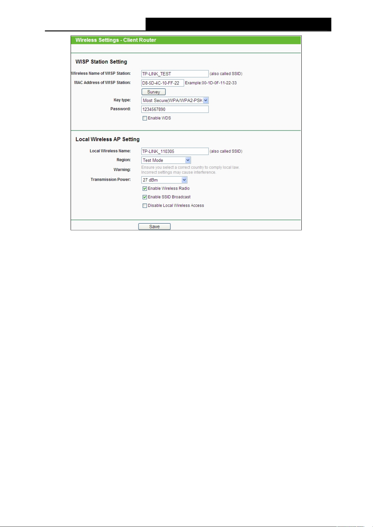
Ensure you select a correct country to comply with local laws. Incorrect settings may cause
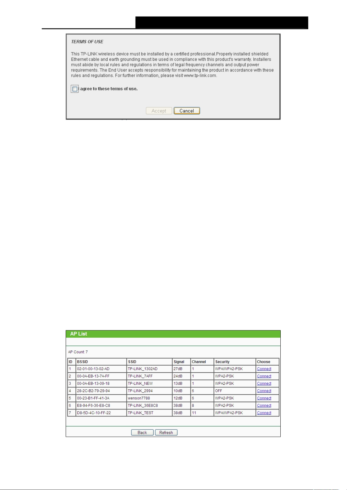
Figure 5-18 AP List
interference. Limited to local law of the United States, selecting country code and channel
function was disabled.
Transmission Power - The available options of transmission power are determined by the
region selected.
Enable Wireless Radio - The wireless radio of the Device can be enabled or disabled to
allow wireless stations access. If enabled, the wireless stations will be able to access the
Device; otherwise, wireless stations will not be able to access the Device.
Enable SSID Broadcast - If you select the Enable SSID Broadcast checkbox,
the AP Router will broadcast its name (SSID) on the air.
Disable Local Wireless Access - If you select the Disable Local
Wireless Access checkbox, the wireless Device will disable local wireless access; other
stations will not be able to access the Device by wireless.
Click Survey button on the Wireless page shown as Figure 5-17, and then AP List
page will appear, as shown in Figure 5-18. Find the SSID of the Access Point you want to
access, and click Connect in the corresponding row. For example, the desired
item is selected. The target network’s SSID will be automatically filled into the
corresponding box which is shown as the Figure
5-19.
85
Page 2
TL-WA7110ND 150Mbps High Power Wireless Access Point User Guide
Note:
Figure 5-19
If you know the SSID of the desired AP, you can also input it to the field "Wireless Name of WISP
Station" manually.
Be sure to click the Save button to save your settings on this page.
Note:
The operating distance or range of your wireless connection varies significantly based
on the physical placement of the Device. For best results, place your Device:
Near the center of the area in which your wireless stations will operate;
In an elevated location such as a high shelf;
Away from the potential sources of interference, such as PCs, microwaves, and
cordless phones;
With the Antenna in the upright position;
Away from large metal surfaces.
Note:
Failure to follow these guidelines can result in significant performance degradation or inability to
wirelessly connect to the Device.
5.7.2 Wireless Security
Selecting Wireless > Wireless Security will enable you to configure the security of the wireless
network for your device on the page as shown in Figure 4-8.
86
Page 3
TL-WA7110ND 150Mbps High Power Wireless Access Point User Guide
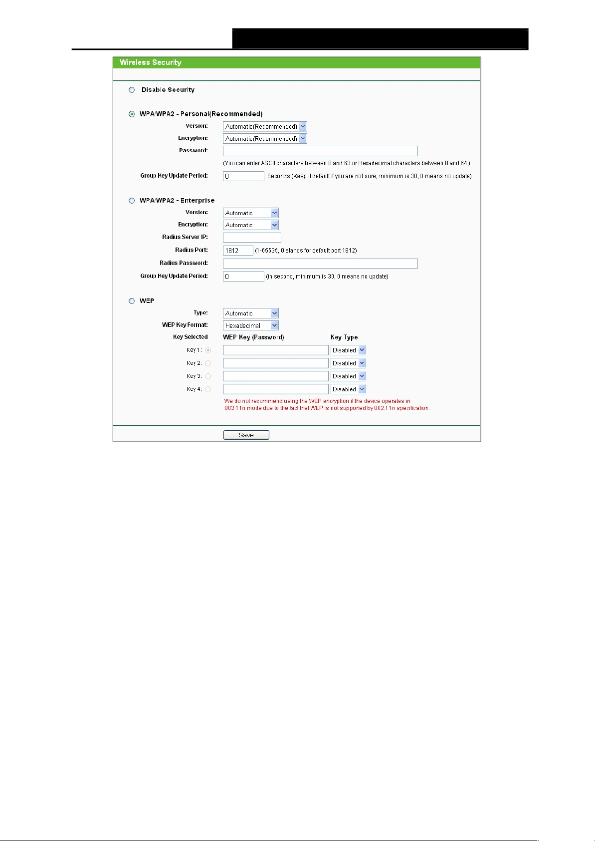
Figure 5-20 Wireless Security
WPA2-Personal - Pre-shared key of WPA2.
Disable Security - The wireless security function can be enabled or disabled. If disabled, the
wireless stations will be able to connect the device without encryption. It is recommended
strongly that you choose one of following options to enable security.
WPA/WPA2-Personal - Select WPA based on Radius Server.
WPA/WPA2-Enterprise - Select WPA based on pre-shared passphrase.
WEP - Select 802.11 WEP security.
Each security option has its own settings as described below:
WPA/WPA2 – Personal (Recommended)
WEP - Select 802.11 WEP security.
Version - You can select one of following versions:
Automatic - Select WPA-Personal or WPA2-Personal automatically based
on the wireless station's capability and request.
WPA-Personal - Pre-shared key of WPA.
Encryption - You can select either Automatic, or TKIP or AES.
Password - You can enter ASCII or Hexadecimal characters. For Hexadecimal, the length
should be between 8 and 64 characters; for ASCII, the length should be between 8 and 63
characters.
87
Page 4

TL-WA7110ND 150Mbps High Power Wireless Access Point User Guide
WPA - Wi-Fi Protected Access.
Open System - Select 802.11 Open System authentication.
For 128-bit encryption - You can enter 26 hexadecimal digits (any combination of 0-9, a-f,
For 152-bit encryption - You can enter 32 hexadecimal digits (any combination of 0-9, a-f,
Note:
Group Key Update Period - Specify the group key update interval in seconds. The value
can be either 0 or at least 30. Enter 0 to disable the update.
WPA/WPA2 - Enterprise
WEP - Select 802.11 WEP security.
Version - You can select one of following versions:
Automatic - Select WPA or WPA2 automatically based on the wireless
station's capability and request.
WPA2 - WPA version 2.
Encryption - You can select either Automatic, or TKIP or AES.
Radius Server IP - Enter the IP address of the Radius Server.
Radius Port - Enter the port that radius service uses.
Radius Password - Enter the password for the Radius Server.
Group Key Update Period - Specify the group key update interval in seconds. The value
can be either 0 or at least 30. Enter 0 to disable the update.
WEP
Type - You can select one of following types:
Automatic - Select Shared Key or Open System authentication type
automatically based on the wireless station's capability and request.
Shared Key - Select 802.11 Shared Key authentication.
WEP Key Format - You can select ASCII or Hexadecimal format. ASCII Format stands for
any combination of keyboard characters in the specified length. Hexadecimal format stands
for any combination of hexadecimal digits (0-9, a-f, A-F) in the specified length.
WEP Key settings - Select which of the four keys will be used and enter the matching WEP
key information for your network in the selected key radio button. These values
must be identical on all wireless stations in your network.
Key Type - You can select the WEP key length (64-bit, or 128-bit, or 152-bit.) for encryption.
"Disabled" means this WEP key entry is invalid.
For 64-bit encryption - You can enter 10 hexadecimal digits (any combination of 0-9, a-f,
A-F, and null key is not permitted) or 5 ASCII characters.
A-F, and null key is not permitted) or 13 ASCII characters.
A-F, and null key is not permitted) or 16 ASCII characters.
If you do not set the key, the wireless security function is still disabled even if you have selected
Shared Key as Authentication Type.
Be sure to click the Save button to save your settings on this page.
5.7.3 MAC Filtering
Selecting Wireless > Wireless MAC Filtering will allow you to set up some
filtering rules to control wireless stations accessing the device, which depend on the station’s
MAC address on the following screen as shown Figure 4-9.
88
Page 5
TL-WA7110ND 150Mbps High Power Wireless Access Point User Guide
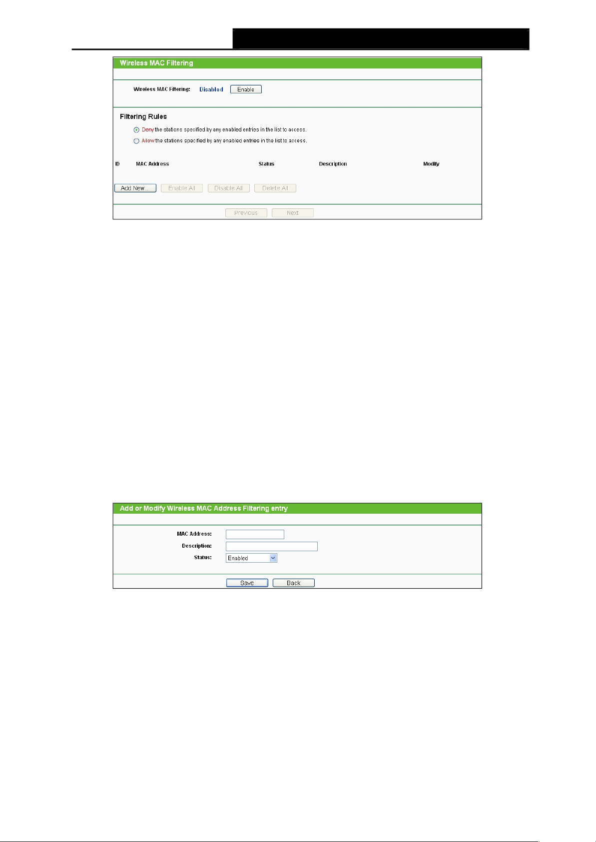
Figure 5-21 Wireless MAC address Filtering
Figure 5-22 Add or Modify Wireless MAC Address Filtering entry
The Wireless MAC Address Filtering feature allows you to control wireless stations accessing the
AP, which depend on the station's MAC addresses.
MAC Address - The wireless station's MAC address that you want to access.
Status - The status of this entry either Enabled or Disabled.
Description - A simple description of the wireless station.
Modify - Here you can modify or delete an existing rule.
To disable the Wireless MAC Address Filters feature, keep the default setting, Disable.
To set up an entry, click Enable, and follow these instructions:
First, you must decide whether the specified wireless stations can or cannot access the AP. If you
desire that the specified wireless stations can access the AP, please select the radio button Allow
the stations specified by any enabled entries in the list to access, otherwise, select the radio
button Deny the stations specified by any enabled entries in the list to access.
To Add a Wireless MAC Address filtering entry, clicking the Add New... button, and following
these instructions: The “Add or Modify Wireless MAC Address Filtering entry"
page will appear, shown in Figure 5-22.
1. Enter the appropriate MAC Address into the MAC Address field. The format of the MAC
Address is XX-XX-XX-XX-XX-XX (X is any hexadecimal digit).
For example,
00-0A-EB-B0-00-0B.
2. Enter a simple description of the wireless station in the Description field. For example,
Wireless station A.
3. Status - Select Enabled or Disabled for this entry on the Status pull-down list.
4. Click the Save button to save this entry.
To add another entries, repeat steps 1~4.
To modify or delete an existing entry:
3. Click the Modify or Delete button in the modify column in the MAC Address
Filtering
Table.
Page 6

89
Page 7
TL-WA7110ND 150Mbps High Power Wireless Access Point User Guide
to access the router, while all other wireless stations cannot access the router, you should configure
4. Enter the value as desired in the Add or Modify Wireless MAC Address Filtering entry
page, and click the Save button.
You can click the Enable All button to make all the Entries enabled, click the Disable All button to
make all the Entries disabled, click the Delete All button to delete all the entries.
Click the Next button to go to the next page and click the Previous button to
return to the previous page.
Note: If you enable the function and select the Allow the stations specified by any enabled
entries in the list to access for Filtering Rules, and there are not any enable entries in the list,
thus, no wireless stations can access the AP.
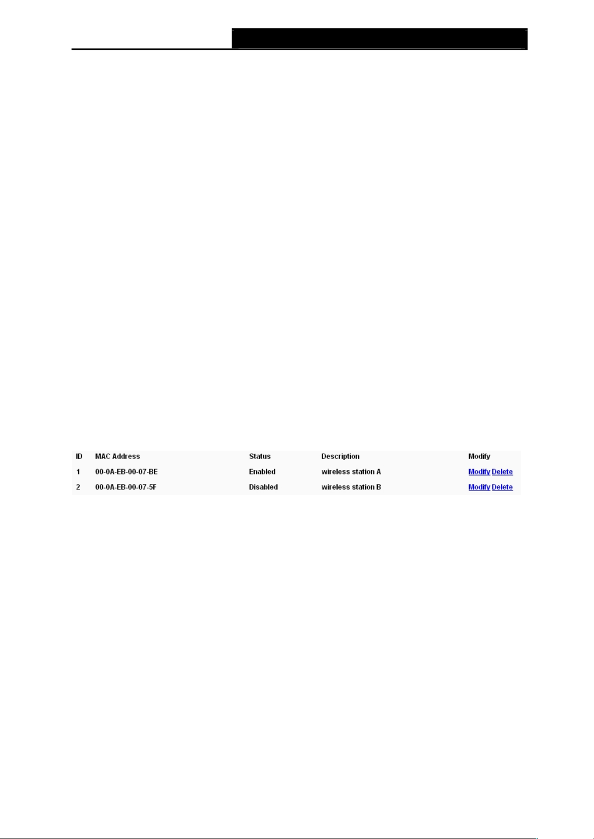
For example: If you desire that the wireless station A with MAC address 00-0A-EB-00- 07-BE be
able to access the router. The wireless station B with MAC address 00-0A-EB- 00-07-5F not be able
the Wireless MAC Address Filtering list by following these steps:
1. Click the Enable button to enable this function.
2. Select the radio button: Allow the stations specified by any enabled entries in the list to
access for Filtering Rules.
3. Delete all or disable all entries if there are any entries already.
4. Click the Add New... button and enter the MAC address 00-0A-EB-00-07-BE in
the MAC Address field, enter wireless station A in the Description field and
select Enabled in the Status pull-down list. Click the Save button.
5. Click the Add New... button and enter the MAC address 00-0A-EB-00-07-5F in
the MAC Address field, enter wireless station B in the Description field and select
Disabled in the Status pull-down list. Click the Save button.
The filtering rules that configured should be similar to the following list:
Note:
1) If you select the radio button Deny the stations specified by any enabled entries in the list
to access for Filtering Rules, the wireless station B will still not be able to access the router,
however, other wireless stations that are not in the list will be able to access the router.
2) If you enable the function and select the Allow the stations specified by any enabled entries
in the list to access for Filtering Rules, and there are not any enable entries in the list, thus,
no wireless stations can access the router.
5.7.4 Wireless Advanced
Selecting Wireless > Wireless Advanced will allow you to do some advanced settings for the
device in the following screen as shown in Figure 5-23. As the configuration for each operation
mode is almost the same, we take Access Point mode for example here.
90
Page 8

TL-WA7110ND 150Mbps High Power Wireless Access Point User Guide
Figure 5-23 Wireless Advanced
a value between 40-1000 milliseconds. The default value is 100.
2346.
Beacon Interval - The beacons are the packets sent by the Device to synchronize a wireless
network. Beacon Interval value determines the time interval of the beacons. You can specify
RTS Threshold - Here you can specify the RTS (Request to Send) Threshold. If the packet
is larger than the specified RTS Threshold size, the Device will send RTS
frames to a particular receiving station and negotiate the sending of a data frame. The
default value is
Fragmentation Threshold - This value is the maximum size determining whether packets
will be fragmented. Setting the Fragmentation Threshold too low may result in poor network
performance since excessive packets. 2346 is the default setting and is recommended.
DTIM Interval - This value determines the interval of the Delivery Traffic Indication Message
(DTIM). You can specify the value between 1-255 Beacon Intervals. The default value is 1,
which indicates the DTIM Interval is the same as Beacon Interval.
Enable WMM - WMM function can guarantee the packets with high-priority messages being
transmitted preferentially. It is strongly recommended enabled.
Enable Short GI - This function is recommended, for it will increase the data capacity by
reducing the guard interval time.
Enable AP Isolation - Isolate all connected wireless stations so that wireless stations cannot
access each other through WLAN. This function will be disabled if WDS/Bridge is enabled.
Note:
If you are not familiar with the setting items in this page, it's strongly recommended to keep the
provided default values; otherwise it may result in lower wireless network performance.
5.7.5 Distance Setting
Selecting Wireless > Distance Setting will allow you to adjust the wireless range
in outdoor conditions as shown in Figure 5-24. This is a critical feature required for stabilizing
outdoor links. Enter the distance of your wireless link and the software will optimize
the frame ACK timeout value automatically.
91
Page 9
TL-WA7110ND 150Mbps High Power Wireless Access Point User Guide
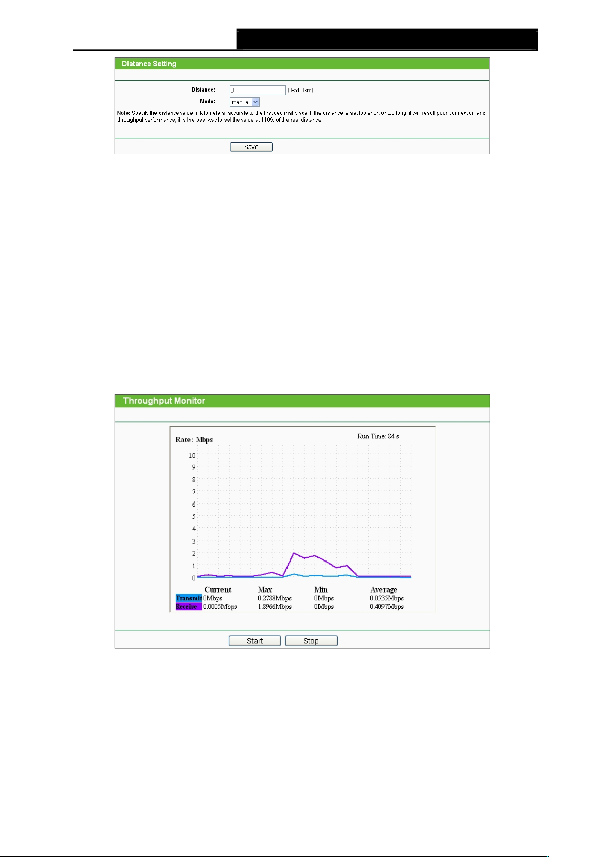
Figure 5-24 Distance Setting
Figure 5-25 Wireless Throughput
Distance - Specify the distance value in kilometers, accurate to the first decimal place. If the
distance is set too short or too long, it will result poor connection and throughput performance,
it is best to set the value at 110% of the real distance. If the AP is being used in an indoor
setting, please use the indoor option.
Note:
One hundred-meter is the smallest unit of this setting.
Mode - You can select manual or indoor for the mode.
Click Save to keep your settings.
5.7.6 Throughput Monitor
Selecting Wireless > Throughput Monitor will helps to watch wireless throughput information in
the following screen shown in Figure 5-25.
Rate - The Throughput unit.
Run Time - How long this function is running.
Transmit- Wireless transmit rate information.
Receive- Wireless receive rate information.
Click the Start button to start wireless throughput monitor.
Click the Stop button to stop wireless throughput monitor.
92
Page 10
TL-WA7110ND 150Mbps High Power Wireless Access Point User Guide
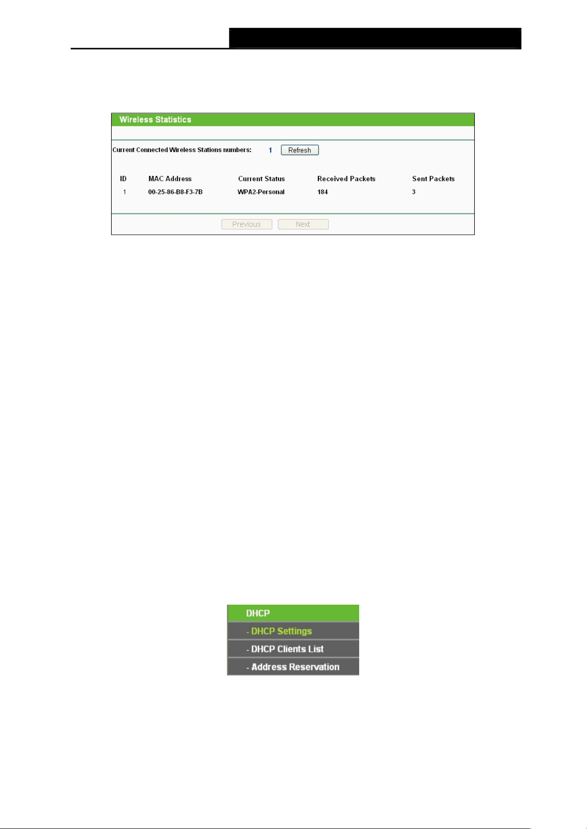
Figure 5-26 The router attached wireless stations
5.7.7 Wireless Statistics
Selecting Wireless > Wireless Statistics will allow you to see the wireless
transmission information in the following screen shown in Figure 5-26.
MAC Address - The connected wireless station's MAC address
Current Status - The connected wireless station's running status, one of STA-
AUTH / STA-ASSOC / AP-UP / WPA / WPA-PSK /WPA2/WPA2-PSK
Received Packets - Packets received by the station
Sent Packets - Packets sent by the station
You cannot change any of the values on this page. To update this page and to show the current
connected wireless stations, click on the Refresh button.
If the numbers of connected wireless stations go beyond one page, click the Next button to go to
the next page and click the Previous button to return the previous page.
Note:
This page will be refreshed automatically every 5 seconds.
5.8 DHCP
DHCP stands for Dynamic Host Configuration Protocol. The DHCP Server will
automatically assign dynamic IP addresses to the computers on the network. This protocol
simplifies network management and allows new wireless devices to receive IP addresses
automatically without the need to manually assign new IP addresses.
There are three submenus under the DHCP menu (shown as Figure 5-27): DHCP
Settings, DHCP Clients List and Address Reservation. Clicking any of them will enable you to
configure the corresponding function. The detailed explanations for each submenu are provided
below.
Figure 5-27 The DHCP menu
5.8.1 DHCP Settings
Selecting DHCP > DHCP Settings will enable you to set up the AP as a DHCP (Dynamic Host
Configuration Protocol) server, which provides the TCP/IP configuration for all the PCs that are
connected to the system on the LAN. The DHCP Server can be configured on the page (shown as
Figure 5-28).
93
Page 11

TL-WA7110ND 150Mbps High Power Wireless Access Point User Guide
Figure 5-28 DHCP Settings
2880 minutes. The default value is 120 minutes.
DHCP Server - Selecting the radio button before Disable/Enable will
disable/enable the DHCP server on your AP. The default setting is Disable. If you disable
the Server, you must have another DHCP server within your network or else you
must manually configure the computer.
Start IP Address - This field specifies the first address in the IP Address pool. 192.168.0.100
is the default start IP address.
End IP Address - This field specifies the last address in the IP Address pool. 192.168.0.199
is the default end IP address.
Address Lease Time - Enter the amount of time for the PC to connect to the AP with its
current assigned dynamic IP address. The time is measured in minutes. After the time is up,
the PC will be automatically assigned a new dynamic IP address. The range of the time is 1 ~
Default Gateway (optional) - Enter the IP address of the gateway for your LAN. The factory
default setting is 0.0.0.0.
Default Domain (optional) - Enter the domain name of the your DHCP server.
You can leave the field blank.
Primary DNS (optional) - Enter the DNS IP address provided by your ISP. Consult your ISP
if you don’t know the DNS value. The factory default setting is 0.0.0.0.
Secondary DNS (optional) - Enter the IP address of another DNS server if
your ISP
provides two DNS servers. The factory default setting is 0.0.0.0.
Click Save to save the changes.
Note:
To use the DHCP server function of the device, you should configure all computers in the LAN as
"Obtain an IP Address automatically" mode. This function will not take effect until
the device reboots.
5.8.2 DHCP Clients List
Selecting DHCP > DHCP Clients List will enable you to view the Client Name, MAC Address,
Assigned IP and Lease Time for each DHCP Client attached to the device (Figure 5-29).
94
Page 12
TL-WA7110ND 150Mbps High Power Wireless Access Point User Guide
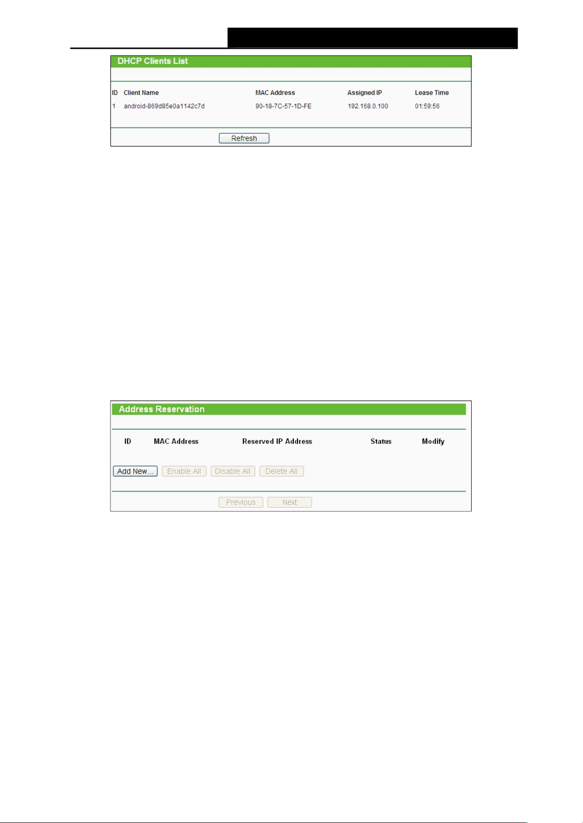
Figure 5-29 DHCP Clients List
Figure 5-30 Address Reservation
ID - Here displays the index of the DHCP client.
Client Name - Here displays the name of the DHCP client.
MAC Address - Here displays the MAC address of the DHCP client.
Assigned IP - Here displays the IP address that the AP has allocated to the DHCP client.
Lease Time - Here displays the time of the DHCP client leased. Before the time is up, DHCP
client will request to renew the lease automatically.
You cannot change any of the values on this page. To update this page and to show the current
attached devices, click on the Refresh button.
5.8.3 Address Reservation
Selecting DHCP > Address Reservation will enable you to specify a reserved IP address for a
PC on the LAN, so the PC will always obtain the same IP address each time when it accesses the
AP. Reserved IP addresses should be assigned to servers that require permanent IP settings.
The screen below is used for address reservation (shown in Figure 5-30).
MAC Address - Here displays the MAC address of the PC for which you want to reserve an
IP address.
Reserved IP Address - Here displays the IP address that the AP is reserved.
Status - Here shows whether the entry is enabled or not
Modify - To modify or delete an existing entry.
To Reserve IP addresses:
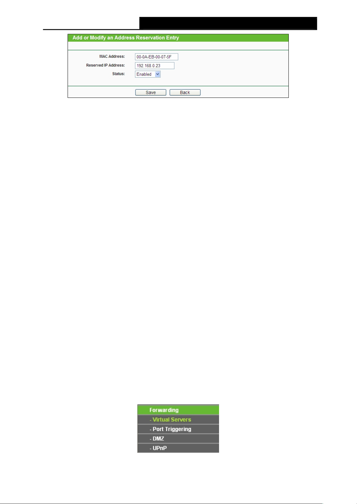
1. Click the Add New button in the page of Address Reservation, the following page (Figure
5-31) will display.
2. Enter the MAC address (the format for the MAC Address is XX-XX-XX-XX-XX-XX) and IP
address in dotted-decimal notation of the computer you want to add.
3. Click the Save button after finish configuring.
95
Page 13
TL-WA7110ND 150Mbps High Power Wireless Access Point User Guide
Figure 5-31 Add or Modify an Address Reservation Entry
Click Next to go to the next page and Click Previous to return the previous page.
To modify A Reserved IP address:
1. Select the reserved address entry to your needs and click Modify. If you wish to delete the
entry, click Delete.
2. Click Save to keep your changes.
To delete all Reserved IP addresses:
Click Clear All.
Note:
The changes won't take effect until the device reboots.
5.9 Forwarding
There are four submenus under the Forwarding menu (shown in Figure 5-32): Virtual Servers,
Port Triggering, DMZ and UPnP. Click any of them, and you will be able to
configure the corresponding function. The detailed explanations for each submenu are provided
below.
Virtual servers can be used for setting up public services on your LAN, such as DNS, Email and
FTP. A virtual server is defined as a service port, and all requests from the Internet to this service
port will be redirected to the computer specified by the server IP. Any PC that was used for a
virtual server must have a static or reserved IP Address because its IP Address
may change when using the DHCP function. Port Triggering is used for some applications
that cannot work with a pure NAT router, like Internet games, video conferencing, Internet calling
and so on, which require multiple connections. The DMZ host feature allows one local host to
be exposed to the Internet for a special-purpose service such as Internet gaming or
videoconferencing. DMZ host forwards all the ports at the same time. Any PC whose
port is being forwarded must have its DHCP client function disabled and should have a new
static IP Address assigned to it because its
IP Address may change when using the DHCP function. The Universal Plug and Play (UPnP)
feature allows the devices, such as Internet computers, to access the local host
resources or devices as needed. UPnP devices can be automatically discovered
by the UPnP service application on the LAN.
Figure 5-32 The Forwarding menu
Page 14

96
Page 15

TL-WA7110ND 150Mbps High Power Wireless Access Point User Guide
Figure 5-33 Virtual Servers
5.9.1 Virtual Servers
Selecting Forwarding > Virtual Servers will allow you to set up virtual servers on the page as
shown in Figure 5-33.
Service Port - The numbers of External Ports. You can type a service port or a range of
service ports (the format is XXX – YYY, XXX is the start port, YYY is the end port).
Internal Port - The Internal Service Port number of the PC running the service application.
You can leave it blank if the Internal Port is the same as the Service Port, or enter a specific
port number when Service Port is a single one.
IP Address - The IP Address of the PC providing the service application.
Protocol - The protocol used for this application, either TCP, UDP, or All (all
protocols supported by the router).
Status - The status of this entry is either Enabled or Disabled.
Modify - To modify or delete an existing entry.
To setup a virtual server entry, please take the following steps:
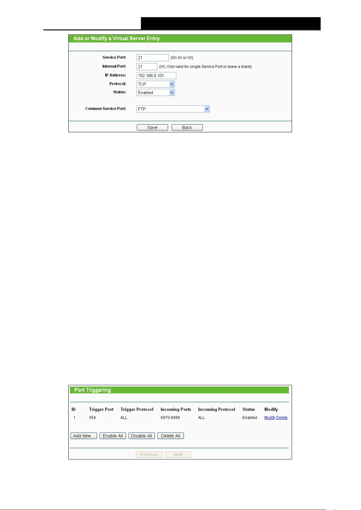
1. Click the Add New… in virtual servers page. (pop-up Figure 5-34)
2. Select the service you want to use from the Common Service Port list. If
the Common Service Port list does not have the service that you want to use, type the
number of the service port or service port range in the Service Port box.
3. Type the IP Address of the computer in the Server IP Address box.
4. Select the protocol used for this application.
5. Select the Enable option to enable the virtual server.
6. Click the Save button.
97
Page 16
TL-WA7110ND 150Mbps High Power Wireless Access Point User Guide
Figure 5-34 Add or Modify a Virtual Server Entry
System Tools → Remote Management page to be any value except 80 such as 8080. Or else
there will be a conflict to disable the virtual server.
Figure 5-35 Port Triggering
Common Service Port - Some common services already exist in the pull-down list.
Note:
It is possible that you have a computer or server that has more than one type of available service.
If so, select another service, and enter the same IP Address for that computer or server.
To modify or delete an existing entry:
1. Click the Modify in the entry you want to modify. If you want to delete the entry, click the
Delete.
2. Modify the information.
3. Click the Save button.
Click the Enable All button to make all entries enabled
Click the Disabled All button to make all entries disabled.
Click the Delete All button to delete all entries.
Click the Next button to go to the next page and Click the Previous button to return the previous
page.
Note:
If you set the virtual server of service port as 80, you must set the Web management port on
5.9.2 Port Triggering
Selecting Forwarding > Port Triggering will enable you to set up Port Triggering entries on the
page as shown in Figure 5-35.
98
Page 17
TL-WA7110ND 150Mbps High Power Wireless Access Point User Guide
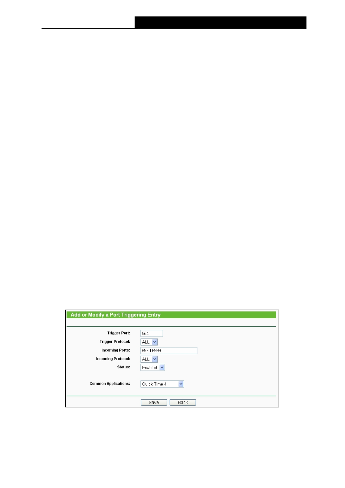
1. Click the Add New… in Port Triggering page. (pop-up Figure 5-36)
Figure 5-36 Add or Modify a Triggering Entry
Once configured, operation is as follows:
1. A local host makes an outgoing connection to an external host using a
destination port number defined in the Trigger Port field.
2. The router records this connection, opens the incoming port or ports associated
with this entry in the Port Triggering table, and associates them with the local host.
3. When necessary the external host will be able to connect to the local host using one of the
ports defined in the Incoming Ports field.
Trigger Port - The port for outgoing traffic. An outgoing connection using this
port will
"Trigger" this rule.
Trigger Protocol - The protocol used for Trigger Ports, TCP, UDP, or All (all
protocols supported by the router).
Incoming Ports Range - The port or port range used by the remote system when it responds
to the outgoing request. A response using one of these ports will be forwarded to the PC that
triggered this rule. You can input at most 5 groups of ports (or port section). Every group of
ports must be set apart with ",". For example, 2000-2038, 2050-2051, 2085, 3010-3030.
Incoming Protocol - The protocol used for Incoming Ports Range, TCP , UDP, or ALL (all
protocols supported by the router).
Status - The status of this entry is either Enabled or Disabled.
To add a new rule, please take the following steps:
2. Select a common application from the Commom Applications drop-list then
the port parameters will be automatically filled in the corresponding field. If the Common
Applicatins list does not have the application you want, type the port parameters manually.
3. Select the protocol used for Trigger Port and Incoming Ports from the
corresponding pull-down list.
4. Select the Enable option in the Status pull-down list..
5. Click the Save button to save the new rule.
To modify or delete an existing entry, please take the following steps:
1. Click the Modify in the entry you want to modify. If you want to delete the entry, click the
Delete.
2. Modify the information.
99
Page 18
TL-WA7110ND 150Mbps High Power Wireless Access Point User Guide
Figure 5-37 DMZ
Figure 5-38 UPnP Settings
3. Click the Save button.
Click Enable All to make all entries enabled.
Click Disabled All to make all entries disabled.
Click Delete All to delete all entries
Note:
1) When the trigger connection is released, the corresponding opening ports will be closed.
2) Each rule can only be used by one host on the LAN at a time. The trigger connection of other
hosts on the LAN will be refused.
3) Incoming Port Range enabled cannot overlap each other at the same time.
5.9.3 DMZ
Selecting Forwarding > DMZ will allow you to set up an DMZ host on the page as
shown in
Figure 5-37.
To assign a computer or server to be a DMZ server:
1. Click the Enable radio button
2. Enter the IP address of a local PC that is desired to be set as the DMZ host in the DMZ Host
IP Address field.
3. Click the Save button.
Note:
After you set the DMZ host, the firewall related to the host will not work.
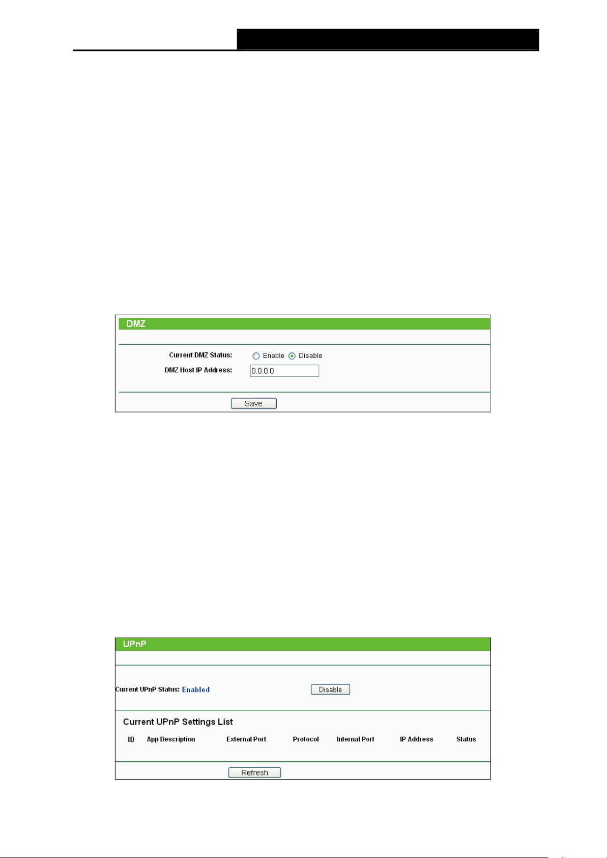
5.9.4 UPnP
Selecting Forwarding > UPnP will enable you to configure the UPnP function on the page as
shown in Figure 5-38:
100
Page 19
TL-WA7110ND 150Mbps High Power Wireless Access Point User Guide
Click Refresh to update the Current UPnP Settings List.
Current UPnP Status - UPnP can be enabled or disabled by clicking the Enable or Disable
button. As enabling UPnP may present a risk to security, this feature is disabled by default.
Current UPnP Settings List - This table displays the current UPnP information.
App Description – The description provided by the application in the UPnP request
External Port - External port, which the router opened for the application.
Protocol - Shows which type of protocol is opened.
Internal Port - Internal port, which the router opened for local host.
IP Address - The IP address of the local host which initiates the UPnP request.
Status - Either Enabled or Disabled, “Enabled” means that port is still active. Otherwise,
the port is inactive.
Click Enable to enable UPnP.
Click Disable to disable UPnP
5.10 Security
Figure 5-39 The Security menu
There are four submenus under the Security menu as shown in Figure 5-39: Basic
Security, Advanced Security, Local Management and Remote Management. Click any of
them, and you will be able to configure the corresponding function.
5.10.1 Basic Security
Choose menu Security > Basic Security, and then you can configure the basic security in the
screen as shown in Figure 5-40.
101
Page 20

TL-WA7110ND 150Mbps High Power Wireless Access Point User Guide
Figure 5-40 Basic Security
to the protocol. SPI Firewall is enabled by factory default. If you want all the computers on
Firewall - Here you can enable or disable the Device's firewall.
SPI Firewall - Stateful Packet Inspection (SPI) helps to prevent cyber attacks by tracking
more state per session. It validates that the traffic passing through the session conforms
the LAN exposed to the outside world, you can disable it.
VPN - VPN Passthrough must be enabled if you want to allow VPN tunnels
using VPN
protocols to pass through the Device.
PPTP Passthrough - PPTP (Point-to-Point Tunneling Protocol) allows the Point-to-Point
Protocol (PPP) to be tunneled through an IP network. To allow PPTP tunnels to pass
through the Device, click Enable.
L2TP Passthrough - L2TP (Layer Two Tunneling Protocol) is the method used to enable
Point-to-Point sessions via the Internet on the Layer Two level. To allow L2TP tunnels to
pass through the Device, click Enable.
IPSec Passthrough - IPSec (Internet Protocol security) is a suite of
protocols for ensuring private, secure communications over IP (Internet Protocol)
networks, through the use of cryptographic security services. To allow IPSec tunnels
to pass through the Device, click Enable.
ALG - It is recommended to enable Application Layer Gateway (ALG) because ALG allows
customized Network Address Translation (NAT) traversal filters to be plugged
into the gateway to support address and port translation for certain application layer
"control/data" protocols such as FTP, TFTP, H323 etc.
FTP ALG - To allow FTP clients and servers to transfer data across NAT, click Enable.
TFTP ALG - To allow TFTP clients and servers to transfer data across NAT, click Enable.
102
Page 21

TL-WA7110ND 150Mbps High Power Wireless Access Point User Guide
Note:
Figure 5-41 Advanced Security
H323 ALG - To allow Microsoft NetMeeting clients to communicate across NAT,
click
Enable.
RTSP ALG -
media servers across NAT, click Enable.
Click the Save button to save your settings.
To allow some media player clients to communicate with some streaming
5.10.2 Advanced Security
Choose menu Security > Advanced Security, and then you can protect the Device from being
attacked by ICMP-Flood, UDP Flood and TCP-SYN Flood in the screen as shown in Figure 5-41.
FLOOD Filtering will take effect only when the Traffic Statistics in System Tools is enabled.
Packets Statistics interval (5~60) - The default value is 10. Select a value between 5 and
60 seconds in the pull-down list. The Packets Statistic interval value indicates
the time section of the packets statistic. The result of the statistic used for analysis by
ICMP-Flood, UDP Flood and TCP-SYN Flood.
DoS Protection - Enable or Disable the DoS protection function. Only when it is enabled, will
the flood filters be enabled.
Enable ICMP-FLOOD Attack Filtering - Enable or Disable the ICMP-
FLOOD Attack
Filtering.
ICMP-FLOOD Packets Threshold (5~3600) - The default value is 50. Enter a value between
5 ~ 3600. When the current ICMP-FLOOD Packets number is beyond the set
value, the
Device will start up the blocking function immediately.
Page 22

103
Page 23

TL-WA7110ND 150Mbps High Power Wireless Access Point User Guide
Figure 5-42 Local Management
Enable UDP-FLOOD Filtering - Enable or Disable the UDP-FLOOD Filtering.
UDP-FLOOD Packets Threshold (5~3600) - The default value is 500.
Enter a value between 5 ~ 3600. When the current UPD-FLOOD Packets number is
beyond the set value, the Device will start up the blocking function immediately.
Enable TCP-SYN-FLOOD Attack Filtering - Enable or Disable the TCP-SYN-
FLOOD Attack Filtering.
TCP-SYN-FLOOD Packets Threshold (5~3600) - The default value is 50. Enter
a value between 5 ~ 3600. When the current TCP-SYN-FLOOD Packets numbers is
beyond the set value, the Device will start up the blocking function immediately.
Ignore Ping Packet From WAN Port - Enable or Disable Ignore Ping Packet From WAN
Port. The default setting is Disabled. If enabled, the ping packet from Internet cannot access
the Device.
Forbid Ping Packet From LAN Port - Enable or Disable Forbid Ping Packet From LAN Port.
The default setting is Disabled. If enabled, the ping packet from LAN cannot
access the Device and defend against some viruses.
Click the Save button to save the settings.
Click the Blocked DoS Host List button to display the DoS host table by blocking.
5.10.3 Local Management
Choose menu Security > Local Management, and then you can configure the management rule
in the screen as shown in Figure 5-42. The management feature allows you to deny computers in
LAN from accessing the Device.
By default, the radio button All the PCs on the LAN are allowed to access
the Router's Web-Based Utility is selected. If you want to allow PCs with specific MAC
Addresses to access the Setup page of the Device's Web-Based Utility locally, from inside the
network, click the radio button Only the PCs listed can browse the built-in web
pages to perform Administrator tasks, and then enter each MAC Address in a separate
field. The format for the MAC Address is XX-XX-XX-XX-XX-XX (X is any hexadecimal digit). Only
the PCs with the MAC address listed can use the password to browse the built-in web
pages to perform Administrator tasks and all the others will be blocked.
104
Page 24

TL-WA7110ND 150Mbps High Power Wireless Access Point User Guide
Figure 5-43 Remote Management
of the children, their access to certain websites, as well as the time of surfing.
After click the Add button, your PC's MAC Address will be placed in the Control List above.
Click the Save button to save your settings.
Note:
If your PC is blocked and you want to access the Device again, use a pin to press and hold the
Reset Button on the back panel about 5 seconds to reset the Device's factory defaults in the
Device's Web-Based Utility.
5.10.4 Remote Management
Choose menu Security > Remote Management, and then you can configure
the Remote Management function in the screen as shown in Figure 5-43. This feature allows
you to manage your Device from a remote location via the Internet.
Web Management Port - Web browser access normally uses the standard HTTP service
port 80. This Device's default remote management web port number is 80.
For greater security, you can change the remote management web port to a custom port by
entering that number in the box provided. Choose a number between 1 and
65535 but do not use the number of any common service port.
Remote Management IP Address - This is the current address you will use when accessing
your Device from the Internet. This function is disabled when the IP address is set to
the default value of 0.0.0.0. To enable this function you should change 0.0.0.0
to a valid IP address. If set to be 255.255.255.255, then all the hosts can access the
Device from Internet.
To access the Device, you should enter your Device's WAN IP address into
your browser's address (in IE) or location (in Netscape) box, followed by a colon and the custom
port number you set in the Web Management Port box.
For example, if your Device's WAN address is 202.96.12.8 and you use port number 8080,
enter http://202.96.12.8:8080 in your browser. You will be asked for the Device's password.
After successfully entering the password, you will be able to access the Device's web-based
utility.
Note:
Be sure to change the Device's default password to a secure password.
5.11 Parental Control
Choose menu Parental Control, and then you can configure the parental control in the screen as
shown in Figure 5-44. The Parental Control function can be used to control the Internet activities
105
Page 25

TL-WA7110ND 150Mbps High Power Wireless Access Point User Guide
Figure 5-44 Parental Control Settings
Parental Control - Check Enable if you want this function to take effect; otherwise check
Disable.
MAC Address of Parental PC - In this field, enter the MAC address of the controlling PC, or
you can make use of the Copy To Above button below.
MAC Address of Your PC - This field displays the MAC address of the PC that is managing
this Device. If the MAC Address of your adapter is registered, you can click the Copy To
Above button to fill this address to the MAC Address of Parental PC field above.
Website Description - Description of the allowed website for the PC controlled.
Schedule - The time period allowed for the PC controlled to access the Internet. For detailed
information, please go to Access Control > Schedule.
Modify - Here you can edit or delete an existing entry.
For example: If you desire that the children’s PC with MAC address 00-11-22-33-44-AA can
access www.google.com on Saturday only while the parent PC with MAC
address
00-11-22-33-44-BB is without any restriction, you should follow the settings below:
1. Click Parental Control menu on the left to enter the Parental Control Settings page. Check
Enable and enter the MAC address 00-11-22-33-44-BB in the MAC Address of Parental PC
field.
2. Click Access Control > Schedule on the left to enter the Schedule Settings page. Click
Add New... button to create a new schedule with Schedule Description is Schedule_1, Day
is Sat and Time is "all day-24 hours".
3. Click Parental Control menu on the left to go back to the Parental Control Settings page,
and then follow the instructions below.
Click Add New... button.
1)
Enter 00-11-22-33-44-AA in the MAC Address of Child PC field.
2)
3) Enter Allow Google in the Website Description field.
4) Enter www.google.com in the Allowed Domain Name field.
Select Schedule_1 you create just now from the Effective Time drop-down list.
5)
6) In Status field, select Enable.
Click Save to complete the settings.
7)
106
Page 26

TL-WA7110ND 150Mbps High Power Wireless Access Point User Guide
Figure 5-45 Parental Control List
4. Then you will go back to the Parental Control Settings page and see the following list.
Click the Add New... button to add a new Parental Control entry.
Click the Enable All button to enable all the rules in the list.
Click the Disable All button to disable all the rules in the list.
Click the Delete All button to delete all the entries in the table.
Click the Next button to go to the next page.
Click the Previous button return to the previous page.
5.12 Access Control
Figure 5-46 Access Control
There are four submenus under the Access Control menu as shown in Figure 5-46: Rule, Host,
Target and Schedule. Click any of them, and you will be able to configure the corresponding
function.
The Device, providing convenient and strong Internet access control function, can control the
Internet activities of hosts in the LAN. Moreover, you can flexibly combine the Host List, Target
List and Schedule to restrict the Internet surfing of these hosts.
5.12.1 Rule
Choose menu Access Control > Rule, and then you can view and set Access Control rules in the
screen as shown in Figure 5-47.
107
Page 27

TL-WA7110ND 150Mbps High Power Wireless Access Point User Guide
Figure 5-47 Access Control Rule Management
Enable Internet Access Control - Select the check box to enable the Internet
Access
Control function, and then the Default Filter Policy can take effect.
Rule Name - Here displays the name of the rule and this name is unique.
Host - Here displays the host selected in the corresponding rule.
Target - Here displays the target selected in the corresponding rule.
Schedule - Here displays the schedule selected in the corresponding rule.
Status - This field displays the status of the rule. Enabled means the rule will take effect,
Disabled means the rule will not take effect.
Modify - Here you can edit or delete an existing rule.
For example: If you desire to allow the host with MAC address 00-11-22-33-44-AA to access
www.google.com only from 18:00 to 20:00 on Saturday and Sunday, and forbid other hosts in the
LAN to access the Internet, you should follow the settings below:
1. Click the submenu Rule of Access Control in the left to return to the Rule List page.
Select Enable Internet Access Control and choose Allow the packets specified by any
enabled access control policy to pass through the Device.
2. We recommend that you click Setup Wizard button to finish all the following settings.
3. Click the submenu Host of Access Control on the left to enter the Host Setting page. Add a
new entry with the Host Description as Host_1 and MAC Address as 00-11-22-33-44-AA.
4. Click the submenu Target of Access Control on the left to enter the Target Settings
page. Add a new entry with the Target Description as Target_1 and
Domain Name as www.google.com.
5. Click the submenu Schedule of Access Control on the left to enter the Schedule
Settings page. Add a new entry with the Schedule Description as Schedule_1, Day as Sat
and Sun, Start Time as 1800 and Stop Time as 2000.
6. Click Add New... button to add a new rule as follows:
108
Page 28

TL-WA7110ND 150Mbps High Power Wireless Access Point User Guide
Figure 5-48 Access Control List
Figure 5-49 Host Settings
In Rule Name field, create a name for the rule. Note that this name should be unique, for
1)
example Rule_1.
2) In Host field, select Host_1.
3) In Target field, select Target_1.
4) In Schedule field, select Schedule_1.
In Action field, select Allow.
5)
In Status field, select Enable.
6)
Click Save to complete the settings.
7)
7. Then you will go back to the Access Control Rule Management page and see the following list.
Click the Add New... button to add a new host list entry.
Click the Enable All button to enable all the rules in the list.
Click the Disable All button to disable all the rules in the list.
Click the Delete All button to delete all the entries in the table.
Click the Next button to go to the next page.
Click the Previous button return to the previous page.
5.12.2 Host
Choose menu Access Control > Host, and then you can view and set a Host list in the screen as
shown in Figure 5-49. The host list is necessary for the Access Control Rule.
Host Description - Here displays the description of the host and this description is unique.
Information - Here displays the information about the host. It can be IP or MAC.
Modify - To modify or delete an existing entry.
109
Page 29

TL-WA7110ND 150Mbps High Power Wireless Access Point User Guide
Figure 5-50 Host List
Figure 5-51 Target Settings
For example: If you desire to restrict the Internet activities of host with
MAC address
00-11-22-33-44-AA, you should follow the settings below:
1. Click Add New... button to enter the Add or Modify a Host Entry page.
2. In Mode field, select MAC Address from the drop-down list.
3. In Host Name field, create a unique description for the host, for example Host_1.
4. In MAC Address field, enter 00-11-22-33-44-AA.
5. Click Save to complete the settings.
6. Go back to the Host Settings page and you will see the following list.
Click the Add New... button to add a new host list entry.
Click the Delete All button to delete all the entries in the table.
Click the Next button to go to the next page.
Click the Previous button return to the previous page.
5.12.3 Target
Choose menu Access Control > Target, and then you can view and set a Target
list in the screen as shown in Figure 5-51. The target list is necessary for the Access Control Rule.
Target Description - Here displays the description about the target and this description is
unique.
Information - The target can be IP address, port, or domain name.
Modify - To modify or delete an existing entry.
For example: If you desire to restrict the Internet activities of host with
MAC address
00-11-22-33-44-AA in the LAN to access www.google.com only, you should first follow the
settings below:
1. Click Add New… button to enter Add or Modify an Access Target Entry page.
2. In Mode field, select Domain Name from the drop-down list.
3. In Target Description field, create a unique description for the target, for example Target_1.
Page 30

110
Page 31

TL-WA7110ND 150Mbps High Power Wireless Access Point User Guide
Figure 5-52 Access Target List
Click the Previous button return to the previous page.
Figure 5-53 Schedule Settings
4. In Domain Name field, enter www.google.com.
5. Click Save to complete the settings.
6. Go back to the Target Settings page and see the following list
Click the Add New... button to add a new target entry.
Click the Delete All button to delete all the entries in the table.
Click the Next button to go to the next page.
5.12.4 Schedule
Choose menu Access Control > Schedule, you can view and set a Schedule list in the next
screen as shown in Figure 5-53. The Schedule list is necessary for the Access Control Rule.
Schedule Description - Here displays the description of the schedule and this description is
unique.
Day - Here displays the day(s) in a week.
Time - Here displays the time period in a day.
Modify - Here you can edit or delete an existing schedule.
For example: If you desire to restrict the Internet activities of host with
MAC address
00-11-22-33-44-AA to access www.google.com only from 18:00 to 20:00 on Saturday and
Sunday, you should first follow the settings below:
1. Click Add New... button to enter the Advance Schedule Settings page.
2. In Schedule Description field, create a unique description for the schedule, for
example
Schedule_1.
3. In Day field, choose Select Days and select Sat and Sun.
4. In Time field, enter 1800 in Start Time and 2000 in Stop Time.
5. Click Save to complete the settings.
6. Go back to the Schedule Settings page and see the following list
Page 32

111
Page 33

TL-WA7110ND 150Mbps High Power Wireless Access Point User Guide
Figure 5-54 Schedule List
Click the Previous button return to the previous page.
To add static routing entries:
Figure 5-56 Static Routing
Click the Add New... button to add a new target entry.
Click the Delete All button to delete all the entries in the table.
Click the Next button to go to the next page.
5.13 Advanced Routing
Figure 5-55 Access Control
There are two submenus under the Advanced Routing as shown in Figure 5-55: Static Routing
List and System Routing Table. Click any of them, and you will be able to
configure the corresponding function.
5.13.1 Static Routing List
A static route is a pre-determined path that network information must travel to reach a specific
host or network. To add or delete a route, work in the area under the Static Routing page
as shown in Figure 5-56.
1. Click the Add New button. (pop up Figure 5-57)
2. Enter the following parameters.
Destination IP Address - The Destination IP Address is the address of the network or host
that you want to assign to a static route.
Subnet Mask - The Subnet Mask determines which portion of an IP Address is the network
portion, and which portion is the host portion.
Default Gateway - This is the IP Address of the gateway device that allows
for contact between the router and the network or host.
112
Page 34

TL-WA7110ND 150Mbps High Power Wireless Access Point User Guide
Figure 5-57 Add or Modify a Static Route Entry
Figure 5-58 System Routing Table
3. Select Enabled or Disabled for this entry from the Status pull-down list.
4. Click the Save button to save the changes.
To modify or delete an existing entry:
1. Click the Modify in the entry you want to modify. If you want to delete the entry, click the
Delete.
2. Modify the information.
3. Click the Save button.
Click the Enable All button to make all entries enabled.
Click the Disabled All button to make all entries disabled.
Click the Delete All button to delete all entries.
5.13.2 System Routing Table
Choose menu System Routing Table > Rule, and then you can view all of the valid route entries
in use in the screen as shown in Figure 5-58.The Destination IP address, Subnet Mask, Gateway,
and Interface will be displayed for each entry.
Destination Network - The Destination Network is the address of the network or
host to which the static route is assigned.
Subnet Mask - The Subnet Mask determines which portion of an IP address is the network
portion, and which portion is the host portion.
Gateway - This is the IP address of the gateway device that allows for contact between the
Device and the network or host.
Interface - This interface tells you whether the Destination IP Address is on the
LAN & WLAN (internal wired and wireless networks), the WAN(Internet).
You can click the Refresh button to refresh the data displayed.
113
Page 35

TL-WA7110ND 150Mbps High Power Wireless Access Point User Guide
Figure 5-60 Bandwidth Control Settings
Figure 5-61 Bandwidth Control Rules List
5.14 Bandwidth Control
Figure 5-59 Bandwidth Control
There are two submenus under the Bandwidth Control menu as shown in Figure 5-59: Control
Settings and Rules List. Click any of them, and you will be able to configure the corresponding
function. The detailed explanations for each submenu are provided below.
5.14.1 Control Settings
Choose menu Bandwidth Control > Control Settings, and then you can configure the Egress
Bandwidth and Ingress Bandwidth in the next screen (shown in Figure 5-60). Their values should
be configured less than 1000000Kbps.
Enable Bandwidth Control - If enabled, the Bandwidth Control rules will take effect.
Egress Bandwidth - The upload speed through the WAN port.
Ingress Bandwidth - The download speed through the WAN port.
5.14.2 Rules List
Choose menu “Bandwidth Control > Rules List”, and then you can view and
configure the
Bandwidth Control rules in the screen below.
ID - The sequence of entry.
114
Page 36

TL-WA7110ND 150Mbps High Power Wireless Access Point User Guide
Figure 5-63 Binding Setting
Description - The information of description include address range, the port
range and protocol of transport layer.
Egress Bandwidth - The max upload speed which through the WAN port. The
default number is 0.
Ingress Bandwidth - The max download speed which through the WAN port. The default
number is 0.
Enable - Rule status, which shows whether the rule takes effect.
Modify - Choose to modify or delete an existing entry.
5.15 IP & MAC Binding
ARP Binding is useful for controlling access of specific computers in the LAN. This page displays
the IP & MAC Binding Setting table; you can operate it in accord with your desire.
There are two submenus under the IP & MAC Binding menu (shown in Figure 5-62): Binding
Setting and ARP List. Click any of them, and you will be able to configure the corresponding
function. The detailed explanations for each submenu are provided below.
Figure 5-62 the IP & MAC Binding menu
5.15.1 Binding Setting
Selecting IP & MAC Binding > Binding Setting will allow you to configure the binding entries, as
shown in Figure 5-63.
MAC Address - The MAC address of the controlled computer in the LAN.
IP Address - The assigned IP address of the controlled computer in the LAN.
Bind - Check this option to enable ARP binding for a specific device.
Modify - To modify or delete an existing entry.
When you want to add or modify an IP & MAC Binding entry, you can click the Add New button
or Modify button, and then you will go to the next page. This page is used
for adding or modifying an IP & MAC Binding entry (shown in Figure 5-64).
115
Page 37

TL-WA7110ND 150Mbps High Power Wireless Access Point User Guide
Figure 5-64 IP & MAC Binding Setting (Add & Modify)
Figure 5-65 Find IP & MAC Binding Entry
To add IP & MAC Binding entries, follow the steps below.
1. Click the Add New... button as shown in Figure 5-63.
2. Enter the MAC Address and IP Address.
3. Select the Bind checkbox.
4. Click the Save button to save it.
To modify or delete an existing entry, follow the steps below.
1. Find the desired entry in the table.
2. Click Modify or Delete as desired on the Modify column.
To find an existing entry, follow the steps below.
1. Click the Find button as shown in Figure 5-63.
2. Enter the MAC Address or IP Address.
3. Click the Find button in the page as shown in Figure 5-65.
Click the Enable All button to make all entries enabled.
Click the Delete All button to delete all entries.
5.15.2 ARP List
Selecting IP & MAC Binding > ARP List will enable you to observe the computers in the LAN by
checking the relationship of MAC address and IP address on the ARP list,
and you could configure the items on the ARP list also. This page displays the ARP List; it
shows all the existing
IP & MAC Binding entries (shown in Figure 5-66).
116
Page 38

TL-WA7110ND 150Mbps High Power Wireless Access Point User Guide
Figure 5-66 ARP List
MAC Address - The MAC address of the controlled computer in the LAN.
IP Address - The assigned IP address of the controlled computer in the LAN.
Status - Indicates whether or not the MAC and IP addresses are bound.
Configure - Load or delete an item.
Load - Load the item to the IP & MAC Binding list.
Delete - Delete the item.
Click the Bind All button to bind all the current items, available after enable.
Click the Load All button to load all items to the IP & MAC Binding list.
Click the Refresh button to refresh all items.
Note:
An item could not be loaded to the IP & MAC Binding list if the IP address of the item has been
loaded before. Error warning will prompt as well. Likewise, "Load All" only loads the items without
interference to the IP & MAC Binding list.
5.16 Dynamic DNS
The Device offers a Dynamic Domain Name System (DDNS) feature. DDNS lets you assign a
fixed host and domain name to a dynamic Internet IP address. It is useful when you are hosting
your own website, FTP server, or other server behind the Device. Before using this feature, you
need to sign up for DDNS service providers such as www.comexe.cn,
www.dyndns.org, or www.no-ip.com. The Dynamic DNS client service provider will give you a
password or key.
1. If the dynamic DNS Service Provider you select is www.comexe.cn, the page will appear as
shown in Figure 5-67.
117
Page 39

TL-WA7110ND 150Mbps High Power Wireless Access Point User Guide
Figure 5-67
Comexe.cn DDNS Settings
Note:
To set up for DDNS, follow these instructions:
1) Enter the Domain Names your dynamic DNS service provider gave.
2) Enter the User Name for your DDNS account.
3) Enter the Password for your DDNS account.
4) Click the Login button to login the DDNS service.
Connection Status - The status of the DDNS service connection is displayed here.
Click Logout to logout the DDNS service.
If you want to login again with another account after a successful login, please click the Logout
button, then input your new username and password and click the Login button.
2. If the dynamic DNS Service Provider you select is www.dyndns.org, the page will appear as
shown in Figure 5-68.
118
Page 40

TL-WA7110ND 150Mbps High Power Wireless Access Point User Guide
Figure 5-68 Dyndns.org DDNS Settings
To set up for DDNS, follow these instructions:
1) Enter the User Name for your DDNS account.
2) Enter the Password for your DDNS account.
3) Enter the Domain Name you received from dynamic DNS service provider.
4) Click the Login button to login to the DDNS service.
Connection Status - The status of the DDNS service connection is displayed here.
Click Logout to logout of the DDNS service.
Note:
If you want to login again with another account after a successful login, please click the Logout
button, then input your new username and password and click the Login button.
3. If the dynamic DNS Service Provider you select is www.no-ip.com, the page will appear as
shown in Figure 5-69.
119
Page 41

TL-WA7110ND 150Mbps High Power Wireless Access Point User Guide
Figure 5-69 No-ip.com DDNS Settings
To set up for DDNS, follow these instructions:
1. Enter the User Name for your DDNS account.
2. Enter the Password for your DDNS account.
3. Enter the Domain Name you received from dynamic DNS service provider.
4. Click the Login button to login to the DDNS service.
Connection Status - The status of the DDNS service connection is displayed here.
Click Logout to logout of the DDNS service.
Note:
If you want to login again with another account after a successful login, please click the Logout
button, then input your new username and password and click the Login button.
5.17 System Tools
System Tools option helps you to optimize the configuration of your device. You can upgrade the
AP to the latest version of firmware as well as backup or restore the AP’s configuration files. Ping
Watch Dog can help to continuously monitor a particular connection to a remote host. Speed Test
helps to test the connection speed to and from any reachable IP address on current
network, especially when we are building wireless network between devices which are far away
from each other. It’s suggested that you change the default password to a more
secure one because it controls access to the device’s web-based management page.
Besides, you can find out what happened to the system in System Log.
There are twelve submenus under the System Tools menu (shown as Figure 4-20): SNMP, Time
Settings, Diagnostic, Ping Watch Dog, Speed Test, Firmware Upgrade, Factory Defaults,
Backup & Restore, Reboot, Password, System log and Statistics. Clicking any of them will
enable you to configure the corresponding function. The detailed explanations for each submenu
are provided below.
120
Page 42

TL-WA7110ND 150Mbps High Power Wireless Access Point User Guide
5.17.1 Time Settings
Figure 5-70 The System Tools menu
Figure 5-71 Time settings
Choose menu “System Tools > Time Settings”, and then you can configure the time
on the following screen.
Time Zone - Select your local time zone from this pull-down list.
To set time manually:
1. Select your local time zone.
2. Enter the Date in Month/Day/Year format.
3. Enter the Time in Hour/Minute/Second format.
4. Click Save.
For automatic time synchronization:
1. Enter the address or domain of the NTP Server I or NTP Server II.
121
Page 43

TL-WA7110ND 150Mbps High Power Wireless Access Point User Guide
as soon as you successfully login to the Device.
Figure 5-72 Diagnostic Tools
2. Click the Get GMT button to get GMT from the Internet.
To enable Daylight Saving:
1. Select the Enable Daylight Saving checkbox to enable daylight saving function.
2. Schedule the span of time which this function will effect. For example, if you want
this function work at 0 o'clock(am) on the 1st Sunday of April and last until at 6 o'clok(pm)
on the 2nd Saturday of September, you need choose "Apr", "1st", "Sun", "0am" at Start
part and choose "Sep", "2nd", "Sat", "6pm" at the End part.
3. Click the Save button to effect this function.
Note:
1) This setting will be used for some time-based functions such as firewall functions. These time
dependant functions will not work if time is not set. So, it is important to specify time settings
2) The time will be lost if the Device is turned off.
3) The Device will automatically obtain GMT from the Internet if it is configured accordingly.
4) In daylight saving configuration, start time and end time shall be within one year and start
time shall be earlier than end time.
5) After you enable daylight saving function, it will take action in one minute.
5.17.2 Diagnostic
Choose menu “System Tools > Diagnostic”, and then you can transact Ping or
Traceroute function to check connectivity of your network in the following screen.
Diagnostic Tool - Click the radio button to select one diagnostic tool:
Ping - This diagnostic tool troubleshoots connectivity, reachability, and name resolution
to a given host or gateway.
Traceroute - This diagnostic tool tests the performance of a connection.
122
Page 44

Note:
TL-WA7110ND 150Mbps High Power Wireless Access Point User Guide
You can use ping/traceroute to test both numeric IP address or
Note:
Figure 5-73 Diagnostic Results
Figure 5-74 Firmware Upgrade
123
domain name. If pinging/tracerouting the IP address is successful, but
pinging/tracerouting the domain name is not, you might have a name resolution problem. In
this case, ensure that the domain name you are specifying can be resolved by using Domain
Name System (DNS) queries.
IP Address/ Domain Name - Enter the IP Address or Domain Name of the
PC whose connection you wish to diagnose.
Ping Count - Specifies the number of Echo Request messages sent. The default is 4.
Ping Packet Size - Specifies the number of data bytes to be sent. The default is 64.
Ping Timeout - Time to wait for a response, in milliseconds. The default is 800.
Traceroute Max TTL - Set the maximum number of hops (max TTL to be reached) in the
path to search for the target (destination). The default is 20.
Click the Start button to start the diagnostic procedure.
The Diagnostic Results page (as shown in Figure 4-24) displays the result of diagnosis.
If the result is similar to the following screen, the connectivity of the Internet is fine.
1) Only one user can use the diagnostic tools at one time.
2) "Ping Count", "Ping Packet Size" and "Ping Timeout" are Ping Parameters, and "Traceroute
Max TTL" is Traceroute Parameter.
5.17.3 Firmware Upgrade
Choose menu “System Tools > Firmware Upgrade”, and then you can update the latest version
of firmware for the Device on the following screen.
To upgrade the Device's firmware, follow these instructions:
Page 45

TL-WA7110ND 150Mbps High Power Wireless Access Point User Guide
Figure 5-75 Restore Factory Default
Figure 5-76 Backup & Restore
1. Download a most recent firmware upgrade file from our website (www.tp-link.com).
2. Enter or select the path name where you save the downloaded file on the computer into the
File Name blank.
3. Click the Upgrade button.
4. The Device will reboot while the upgrading has been finished.
Firmware Version - Displays the current firmware version.
Hardware Version - Displays the current hardware version. The hardware version
of the upgrade file must accord with the current hardware version.
Note:
The firmware version must correspond to the hardware. The upgrade process
takes a few moments and the Device restarts automatically when the upgrade is complete. It
is important to keep power applied during the entire process. Loss of power during the upgrade
could damage the Device.
5.17.4 Factory Defaults
Choose menu “System Tools > Factory Defaults”, and you can restore the configurations of the
Device to factory defaults on the following screen.
Click the Restore button to reset all configuration settings to their default values.
Default User Name - admin.
Default Password - admin.
Default IP Address - 192.168.0.254.
Default Subnet Mask - 255.255.255.0.
Note:
All changed settings will be lost when defaults are restored.
5.17.5 Backup & Restore
Choose menu “System Tools > Backup & Restore”, and then you can save
the current configuration of the Device as a backup file and restore the configuration via a
backup file as shown in Figure 4-29.
Click the Backup button to save all configuration settings to your local computer as a file.
124
Page 46

TL-WA7110ND 150Mbps High Power Wireless Access Point User Guide
Figure 5-77 Reboot the Device
To restore the AP's configuration, follow these instructions:
1. Click the Browse button to find the configuration file which you want to restore.
2. Click the Restore button to update the configuration with the file whose path is the one you
have input or selected in the blank.
Note:
The current configuration will be covered with the uploading configuration file. Wrong process will
lead the device unmanaged. The restoring process lasts for 20 seconds and the AP will restart
automatically then. Keep the power of the AP on during the process, in case of any damage.
5.17.6 Reboot
Choose menu “System Tools > Reboot”, and then you can click the Reboot button to reboot the
Device via the next screen.
Click the Reboot button to reboot the Device.
Some settings of the Device will take effect only after rebooting, including:
Change the LAN IP Address (system will reboot automatically).
Change the DHCP Settings.
Change the Wireless configurations.
Change the Web Management Port.
Upgrade the firmware of the Device (system will reboot automatically.).
Restore the Device's settings to the factory defaults (system will reboot automatically.).
Update the configuration with the file (system will reboot automatically.).
5.17.7 Password
Choose menu “System Tools > Password”, and then you can change the factory default user
name and password of the Device in the next screen as shown in Figure 4-31.
125
Page 47

TL-WA7110ND 150Mbps High Power Wireless Access Point User Guide
Figure 5-78 Password
Figure 5-79 System Log
It is strongly recommended that you change the factory default user name and password of the
AP. All users who try to access the AP's web-based utility will be prompted for the AP's user name
and password.
Note:
The new user name and password must not exceed 14 characters in length and must not include
any spaces. Enter the new Password twice to confirm it.
Click the Save button when finished.
Click the Clear All button to clear all.
5.17.8 System log
Choose menu “System Tools > System Log”, and then you can view the logs of the Device.
Auto Mail Feature - Indicates whether auto mail feature is enabled or not.
Mail Settings - Set the receiving and sending mailbox address, server address, validation
information as well as the timetable for Auto Mail Feature.
126
Page 48

TL-WA7110ND 150Mbps High Power Wireless Access Point User Guide
Figure 5-80 Mail Account Settings
From - Your mail box address.
To - Recipient's address.
SMTP Server - Your SMTP server.
Authentication - Most SMTP Server requires Authentication.
Note:
Only when you select Authentication, do you have to enter the User Name and Password in the
following fields.
User Name - Your mail account name.
Password - Your mail account password.
Auto Mail Feature will help you monitor how your Device is running.
Everyday, at specified time, the Device will automatically send the log to specified mailbox.
Every few hours, such as 2 hours, the Device will automatically send the log to specified mailbox.
Log Type - By selecting the log type, only logs of this type will be shown.
Log Level - By selecting the log level, only logs of this level will be shown.
Refresh - Refresh the page to show the latest log list.
Save Log - Click to save all the logs in a txt file.
Mail Log - Click to send an email of current logs manually according to the
address and validation information set in Mail Settings. The result will be shown in the later log
soon.
Clear Log - All the logs will be deleted from the Device permanently, not just from the page.
Click the Next button to go to the next page.
Click the Previous button return to the previous page.
127
Page 49

TL-WA7110ND 150Mbps High Power Wireless Access Point User Guide
Figure 5-81 Statistics
Click the Refresh button to refresh the page.
Figure 5-82 Statistics Table
5.17.9 Statistics
Choose menu “System Tools > Statistics”, and then you can view the statistics of the Device,
including total traffic and current traffic of the last Packets Statistic Interval.
The Statistics page shows the network traffic of each PC on the LAN, including total traffic and the
value of the last Packets Statistic interval in seconds.
Current Statistics Status - Enabled or Disabled. The default value is disabled. To enable,
click the Enable button. If disabled, the function of DoS protection in Security settings will be
disabled.
Packets Statistics Interval - The default value is 10. Select a value between
5 and 60 seconds in the pull-down list. The Packets Statistic interval value indicates the
time section of the packets statistic.
Sorted Rules - Choose how displayed statistics are sorted.
Click the Auto-refresh checkbox to refresh automatically.
Click the Reset All button to reset the values of all entries to zero.
Click the Delete All button to delete all entries in the table.
Statistics Table
IP Address/MAC Address - The IP Address and MAC address are displayed with related
statistics.
128
Page 50

Total
TL-WA7110ND 150Mbps High Power Wireless Access Point User Guide
Packets - The total number of packets received and transmitted by the Device.
Bytes - The total number of bytes received and transmitted by the Device.
Current
Packets - The total number of packets received and transmitted in the
last Packets
Statistics interval seconds.
Bytes - The total number of bytes received and transmitted in the last Packets Statistics
interval seconds.
ICMP Tx - The number of ICMP packets transmitted to the WAN per
second at the specified Packets Statistics interval. It is shown like "current
transmitting rate / Max transmitting rate".
UDP Tx - The number of UDP packets transmitted to the WAN per second at the
specified Packets Statistics interval. It is shown like "current transmitting rate /
Max transmitting rate".
TCP SYN Tx - The number of TCP SYN packets transmitted to the WAN per second
at the specified Packets Statistics interval. It is shown like "current transmitting rate /
Max transmitting rate".
Modify
Reset - Reset the values of the entry to zero.
Delete - Delete the existing entry in the table.
129
Page 51

TL-WA7110ND 150Mbps High Power Wireless Access Point User Guide
Appendix A: FAQ
Note:
Figure A-2 PPPoE Connection Mode
1. How do I configure the router to access the Internet by ADSL users?
1) First, configure the ADSL Modem configured in RFC1483 bridge model.
2) Connect the Ethernet cable from your ADSL Modem to the WAN port on the
router. The telephone cord plugs into the Line port of the ADSL Modem.
3) Login to the router, click the “Network” menu on the left of your browser, and click "WAN"
submenu. On the WAN page, select “PPPoE” for WAN Connection Type. Type user name in
the “User Name” field and password in the “Password” field, finish by clicking “Connect”.
Figure A-1 PPPoE Connection Type
4) If your ADSL lease is in “pay-according-time” mode, select “Connect on
Demand” or
“Connect Manually” for the Internet connection mode. Type an appropriate number for “Max
Idle Time” to avoid wasting paid time. Otherwise, you can select “Auto-connecting” for the
Internet connection mode.
1) Sometimes the connection cannot be disconnected although you specify a time to Max Idle
Time, since some applications is visiting the Internet continually in the background.
2) If you are a Cable user, please configure the router following the above steps.
2. How do I configure the router to access the Internet by Ethernet users?
1) Login to the router, click the “Network” menu on the left of your browser, and click "WAN"
submenu. On the WAN page, select “Dynamic IP” for "WAN Connection Type",
finish by clicking “Save”.
2) Some ISPs require that you register the MAC Address of your adapter, which is connected to
your cable/DSL Modem during installation. If your ISP requires MAC register, login
to the
Page 52

130
Page 53

TL-WA7110ND 150Mbps High Power Wireless Access Point User Guide
"WAN MAC Address" field. Or else, type the MAC Address into the "WAN MAC Address" field.
an example, remember to “Enable” and “Save”.
router and click the "Network" menu link on the left of your browser, and then click "MAC
Clone" submenu link. On the "MAC Clone" page, if your PC’s MAC address is proper MAC
address, click the "Clone MAC Address" button and your PC’s MAC address will fill in the
The format for the MAC Address is XX-XX-XX-XX-XX-XX. Then click the "Save" button. It will
take effect after rebooting.
Figure A-3 MAC Clone
3. I want to use Netmeeting, what do I need to do?
1) If you start Netmeeting as a sponsor, you don’t need to do anything with the router.
2) If you start as a response, you need to configure Virtual Server or DMZ Host.
3) How to configure Virtual Server: Login to the router, click the “Forwarding” menu on the left of
your browser, and click "Virtual Servers" submenu. On the "Virtual Server" page, click Add
New, then on the “Add or Modify a Virtual Server” page, enter “1720” into the blank behind
the “Service Port”, and your IP address behind the IP Address, assuming 192.168.0.169 for
Figure A-4 Virtual Servers
Figure A-5 Add or Modify a Virtual server Entry
131
Page 54

Note:
TL-WA7110ND 150Mbps High Power Wireless Access Point User Guide
Your opposite side should call your WAN IP, which is displayed on the “Status” page.
Note:
Figure A-7 Remote Management
“Enable” and “Save”.
4) How to enable DMZ Host: Login to the router, click the “Forwarding” menu on the left of your
browser, and click "DMZ" submenu. On the "DMZ" page, click “Enable” radio and type your IP
address into the “DMZ Host IP Address” field, using 192.168.0.169 as
an example, remember to click the Save button.
Figure A-6 DMZ
4. I want to build a Web Server on the LAN, what should I do?
1) Because the Web Server port 80 will interfere with the Web management port 80
on the router, you must change the Web management port number to avoid interference.
2) To change the Web management port number: Login to the router, click the “Security” menu
on the left of your browser, and click "Remote Management" submenu. On the
"Remote Management" page, type a port number except 80, such as 88, into the "Web
Management Port" field. Click “Save” and reboot the router.
If the above configuration takes effect, to configure to the router by typing http://192.168.0.254:88/
(the router’s LAN IP address: Web Management Port) in the address field of the Web browser.
3) Login to the router, click the “Forwarding” menu on the left of your browser, and click the
"Virtual Servers" submenu. On the "Virtual Server" page, click Add New, then on the “Add or
Modify a Virtual Server” page, enter “80” into the blank behind the “Service Port”, and your IP
address behind the IP Address, assuming 192.168.0.188 for an example,
remember to
132
Page 55

TL-WA7110ND 150Mbps High Power Wireless Access Point User Guide
Figure A-8 Virtual Servers
A-9 Add or Modify a Virtual server Entry
5. The wireless stations cannot connect to the router.
1) Make sure the "AP Router Radio" is enabled.
2) Make sure that the wireless stations' SSID accord with the router's SSID.
3) Make sure the wireless stations have the right KEY for encryption when the
router is encrypted.
4) If the wireless connection is ready, but you can’t access the router, check the IP Address of
your wireless stations.
133
Page 56

TL-WA7110ND 150Mbps High Power Wireless Access Point User Guide
Appendix B: Configuring the PC
Figure B-1
In this section, we’ll introduce how to install and configure the TCP/IP correctly in Windows XP.
First make sure your Ethernet Adapter is working, refer to the adapter’s manual if needed.
1. Configure TCP/IP component
1) On the Windows taskbar, click the start button, and then click Control Panel.
2) Click the Network and Internet Connections icon, and then click on the
Network
Connections tab in the appearing window.
3) Right click the icon that showed below, select Properties on the prompt page.
4) In the prompt page that showed below, double click on the Internet Protocol (TCP/IP).
134
Page 57

TL-WA7110ND 150Mbps High Power Wireless Access Point User Guide
Figure B-2
5) The following TCP/IP Properties window will display and the IP Address tab is open on
this window by default.
Now you have two ways to configure the TCP/IP protocol below:
Setting IP address automatically
Select Obtain an IP address automatically, Choose Obtain DNS server
automatically, as shown in the Figure below:
135
Page 58

TL-WA7110ND 150Mbps High Power Wireless Access Point User Guide
Figure B-3
Note: For Windows 98 OS or before, the PC and router may need to be restarted.
Setting IP address manually
1. Select Use the following IP address radio button. And the following items available
2. If the router's LAN IP address is 192.168.0.254, specify the IP address as 192.168.0.x (x is
from 2 to 253), and the Subnet mask as 255.255.255.0.
3. Type the router’s LAN IP address (the default IP is 192.168.0.254) into the Default gateway
field.
4. Select Use the following DNS server addresses. In the Preferred DNS Server field you
can enter the same value as the Default gateway or type the local DNS server IP address.
136
Page 59

TL-WA7110ND 150Mbps High Power Wireless Access Point User Guide
Now:
Click OK to keep your settings.
Figure B-4
137
Page 60

TL-WA7110ND 150Mbps High Power Wireless Access Point User Guide
Appendix C: Specifications
General
Standards and Protocols
IEEE 802.3, 802.3u, 802.11b, 802.11g and 802.11n, TCP/IP, DHCP
Safety & Emission
FCC, CE
Ports
One 10/100M Auto-Negotiation LAN RJ45 port, supporting passive
PoE
Cabling Type
10BASE-T: UTP category 3, 4, 5 cable (maximum 100m)
EIA/TIA-568 100ΩSTP (maximum 100m)
100BASE-TX: UTP category 5, 5e cable (maximum 100m)
EIA/TIA-568 100ΩSTP (maximum 100m)
Wireless
Wireless Data Rates
up to 150 Mbps
Wireless Encryptions
64/128/152-bit WEP, WPA/WPA2, WPA-PSK/WPA2-PSK
Physical and Environment
Working Temperature
-30℃~70℃
Working Humidity
10% ~ 90% RH, Non-condensing
Storage Temperature
-40℃~70℃(-40℉~158℉)
Storage Humidity
5% ~ 90% RH, Non-condensing
138
Page 61

TL-WA7110ND 150Mbps High Power Wireless Access Point User Guide
Appendix D: Glossary
as Wi-Fi networks.
802.11n - 802.11n builds upon previous 802.11 standards by adding MIMO (multiple-input
multiple-output). MIMO uses multiple transmitter and receiver antennas to
allow for increased data throughput via spatial multiplexing and increased range by
exploiting the spatial diversity, perhaps through coding schemes like Alamouti coding.
The Enhanced Wireless Consortium (EWC) was formed to help
accelerate the IEEE 802.11n development process and promote a
technology specification for interoperability of next-generation wireless local area
networking (WLAN) products.
802.11b - The 802.11b standard specifies a wireless networking at 11
Mbps using direct-sequence spread-spectrum (DSSS) technology and operating in the
unlicensed radio spectrum at 2.4GHz, and WEP encryption for security. 802.11b networks
are also referred to
802.11g - specification for wireless networking at 54 Mbps using
direct-sequence spread-spectrum (DSSS) technology, using OFDM modulation
and operating in the unlicensed radio spectrum at 2.4GHz, and backward compatibility
with IEEE 802.11b devices, and WEP encryption for security.
DDNS (Dynamic Domain Name System) - The capability of assigning a fixed host and domain
name to a dynamic Internet IP Address.
DHCP (Dynamic Host Configuration Protocol) - A protocol that automatically
configure the
TCP/IP parameters for the all the PC(s) that are connected to a DHCP server.
DMZ (Demilitarized Zone) - A Demilitarized Zone allows one local host to be exposed to the
Internet for a special-purpose service such as Internet gaming or videoconferencing.
DNS (Domain Name System) – An Internet Service that translates the names of websites into
IP addresses.
Domain Name - A descriptive name for an address or group of addresses on the Internet.
DoS (Denial of Service) - A hacker attack designed to prevent your computer or network from
operating or communicating.
DSL (Digital Subscriber Line) - A technology that allows data to be sent or
received over existing traditional phone lines.
ISP (Internet Service Provider) - A company that provides access to the Internet.
MTU (Maximum Transmission Unit) - The size in bytes of the largest packet that can be
transmitted.
NAT (Network Address Translation) - NAT technology translates IP addresses of a local area
network to a different IP address for the Internet.
PPPoE (Point to Point Protocol over Ethernet) - PPPoE is a protocol for connecting remote
hosts to the Internet over an always-on connection by simulating a dial-up connection.
SSID - A Service Set Identification is a thirty-two character (maximum)
alphanumeric key identifying a wireless local area network. For the
wireless devices in a network to communicate with each other, all devices must
be configured with the same SSID. This is typically the configuration parameter for a
wireless PC card. It corresponds to the ESSID in the wireless Access Point and to the
wireless network name.
WEP (Wired Equivalent Privacy) - A data privacy mechanism based on a 64-bit or 128-bit or
152-bit shared key algorithm, as described in the IEEE 802.11 standard.
Page 62

Wi-Fi - is a trademark of the Wi-Fi Alliance, founded in 1999 as Wireless Internet Compatibility
139
Page 63

TL-WA7110ND 150Mbps High Power Wireless Access Point User Guide
140
Alliance (WICA), comprising more than 300 companies, whose products are certified by the
Wi-Fi Alliance, based on the IEEE 802.11 standards (also called Wireless LAN (WLAN) and
Wi-Fi). This certification warrants interoperability between different wireless devices.
WISP - Wireless Internet Service Providers (WISPs) are Internet service
providers with networks built around wireless networking. The technology used ranges
from commonplace Wi-Fi mesh networking or proprietary equipment designed to
operate over open 900MHz,
2.4GHz, 4.9, 5.2, 5.4, and 5.8GHz bands or licensed frequencies in the UHF or MMDS bands.
WLAN (Wireless Local Area Network) - A group of computers and
associated devices communicate with each other wirelessly, which network serving users
are limited in a local area.
 Loading...