

Page 1

Archer D7
User Guide
AC1750 Wireless Dual Band Gigabit
ADSL2+ Modem Router
REV2.0.0 1910011480
Page 2

Contents
About This Guide . . . . . . . . . . . . . . . . . . . . . . . . . . . . . . . . . . . . . . . . . . . . . . . . . . 1
Chapter 1. Get to Know About Your Modem Router . . . . . . . . . . . . . . . . . 2
1. 1. Product Overview . . . . . . . . . . . . . . . . . . . . . . . . . . . . . . . . . . . . . . . . . . . . . . . . . . . . . . . . . . 3
1. 2. Main Features . . . . . . . . . . . . . . . . . . . . . . . . . . . . . . . . . . . . . . . . . . . . . . . . . . . . . . . . . . . . . . 4
1. 3. Panel Layout . . . . . . . . . . . . . . . . . . . . . . . . . . . . . . . . . . . . . . . . . . . . . . . . . . . . . . . . . . . . . . . 5
1. 3. 1. Top View. . . . . . . . . . . . . . . . . . . . . . . . . . . . . . . . . . . . . . . . . . . . . . . . . . . . . . . . . . . . . 5
1. 3. 2. The Back Panel . . . . . . . . . . . . . . . . . . . . . . . . . . . . . . . . . . . . . . . . . . . . . . . . . . . . . . . 7
Chapter 2. Connect the Hardware. . . . . . . . . . . . . . . . . . . . . . . . . . . . . . . . . . 8
2. 1. Position Your Modem Router . . . . . . . . . . . . . . . . . . . . . . . . . . . . . . . . . . . . . . . . . . . . . . . 9
2. 2. Connect Your Modem Router . . . . . . . . . . . . . . . . . . . . . . . . . . . . . . . . . . . . . . . . . . . . . . . 9
Chapter 3. Log into Your Modem Router. . . . . . . . . . . . . . . . . . . . . . . . . . . 12
Chapter 4. Set Up Internet Connections . . . . . . . . . . . . . . . . . . . . . . . . . . . 14
4. 1. Use Quick Setup Wizard . . . . . . . . . . . . . . . . . . . . . . . . . . . . . . . . . . . . . . . . . . . . . . . . . . . 15
4. 2. Manually Set up an Internet Connection . . . . . . . . . . . . . . . . . . . . . . . . . . . . . . . . . . . 15
4. 3. Set up an IPv6 Connection. . . . . . . . . . . . . . . . . . . . . . . . . . . . . . . . . . . . . . . . . . . . . . . . . 16
4. 4. Test Internet Connectivity . . . . . . . . . . . . . . . . . . . . . . . . . . . . . . . . . . . . . . . . . . . . . . . . . 17
Chapter 5. Bandwidth Control . . . . . . . . . . . . . . . . . . . . . . . . . . . . . . . . . . . . 19
Chapter 6. Network Security. . . . . . . . . . . . . . . . . . . . . . . . . . . . . . . . . . . . . . 23
6. 1. MAC Filtering . . . . . . . . . . . . . . . . . . . . . . . . . . . . . . . . . . . . . . . . . . . . . . . . . . . . . . . . . . . . . 24
6. 2. Access Control . . . . . . . . . . . . . . . . . . . . . . . . . . . . . . . . . . . . . . . . . . . . . . . . . . . . . . . . . . . . 25
6. 3. IP & MAC Binding. . . . . . . . . . . . . . . . . . . . . . . . . . . . . . . . . . . . . . . . . . . . . . . . . . . . . . . . . . 27
Chapter 7. IPTV . . . . . . . . . . . . . . . . . . . . . . . . . . . . . . . . . . . . . . . . . . . . . . . . . . 29
Chapter 8. USB Settings . . . . . . . . . . . . . . . . . . . . . . . . . . . . . . . . . . . . . . . . . . 31
8. 1. Local Storage Sharing . . . . . . . . . . . . . . . . . . . . . . . . . . . . . . . . . . . . . . . . . . . . . . . . . . . . . 32
8. 1. 1. Access the USB disk . . . . . . . . . . . . . . . . . . . . . . . . . . . . . . . . . . . . . . . . . . . . . . . . . 32
Page 3

8. 1. 2. Customize Your Settings. . . . . . . . . . . . . . . . . . . . . . . . . . . . . . . . . . . . . . . . . . . . . 34
8. 2. Remote Access via FTP Server. . . . . . . . . . . . . . . . . . . . . . . . . . . . . . . . . . . . . . . . . . . . . . 38
8. 2. 1. Access the USB disk . . . . . . . . . . . . . . . . . . . . . . . . . . . . . . . . . . . . . . . . . . . . . . . . . 38
8. 2. 2. Customize Your Settings. . . . . . . . . . . . . . . . . . . . . . . . . . . . . . . . . . . . . . . . . . . . . 40
8. 3. Media Sharing. . . . . . . . . . . . . . . . . . . . . . . . . . . . . . . . . . . . . . . . . . . . . . . . . . . . . . . . . . . . . 41
8. 3. 1. Access the USB disk . . . . . . . . . . . . . . . . . . . . . . . . . . . . . . . . . . . . . . . . . . . . . . . . . 42
8. 3. 2. Customize Your Settings. . . . . . . . . . . . . . . . . . . . . . . . . . . . . . . . . . . . . . . . . . . . . 43
8. 4. Printer Sharing . . . . . . . . . . . . . . . . . . . . . . . . . . . . . . . . . . . . . . . . . . . . . . . . . . . . . . . . . . . . 44
Chapter 9. Parental Controls. . . . . . . . . . . . . . . . . . . . . . . . . . . . . . . . . . . . . . 49
Chapter 10. Guest Network . . . . . . . . . . . . . . . . . . . . . . . . . . . . . . . . . . . . . . . . 53
10. 1. Create a Network for Guests . . . . . . . . . . . . . . . . . . . . . . . . . . . . . . . . . . . . . . . . . . . . . . . 54
10. 2. Customize Guest Network Options. . . . . . . . . . . . . . . . . . . . . . . . . . . . . . . . . . . . . . . . . 54
Chapter 11. NAT Forwarding. . . . . . . . . . . . . . . . . . . . . . . . . . . . . . . . . . . . . . . 56
11. 1. Share Local Resources in the Internet by Virtual Server. . . . . . . . . . . . . . . . . . . . . . 57
11. 2. Open Ports Dynamically by Port Triggering. . . . . . . . . . . . . . . . . . . . . . . . . . . . . . . . . 58
11. 3. Make Applications Free from Port Restriction by DMZ . . . . . . . . . . . . . . . . . . . . . . 59
11. 4. Make Xbox Online Games Run Smoothly by UPnP . . . . . . . . . . . . . . . . . . . . . . . . . . 60
Chapter 12. Specify Your Network Settings . . . . . . . . . . . . . . . . . . . . . . . . . 62
12. 1. LAN Settings . . . . . . . . . . . . . . . . . . . . . . . . . . . . . . . . . . . . . . . . . . . . . . . . . . . . . . . . . . . . . . 63
12. 1. 1. Change the LAN IP Address . . . . . . . . . . . . . . . . . . . . . . . . . . . . . . . . . . . . . . . . 63
12. 1. 2. Use the Modem Router as a DHCP Server . . . . . . . . . . . . . . . . . . . . . . . . . . . 63
12. 1. 3. Reserve LAN IP Addresses . . . . . . . . . . . . . . . . . . . . . . . . . . . . . . . . . . . . . . . . . . 64
12. 2. Wireless Settings . . . . . . . . . . . . . . . . . . . . . . . . . . . . . . . . . . . . . . . . . . . . . . . . . . . . . . . . . . 65
12. 2. 1. Specify Basic Wireless Settings. . . . . . . . . . . . . . . . . . . . . . . . . . . . . . . . . . . . . . 65
12. 2. 2. Use WPS for Wireless Connection . . . . . . . . . . . . . . . . . . . . . . . . . . . . . . . . . . . 67
12. 2. 3. Schedule Your Wireless Function . . . . . . . . . . . . . . . . . . . . . . . . . . . . . . . . . . . 69
12. 2. 4. View Wireless Information. . . . . . . . . . . . . . . . . . . . . . . . . . . . . . . . . . . . . . . . . . 70
12. 2. 5. Advanced Wireless Settings . . . . . . . . . . . . . . . . . . . . . . . . . . . . . . . . . . . . . . . . 71
12. 3. Set Up a Dynamic DNS Service Account . . . . . . . . . . . . . . . . . . . . . . . . . . . . . . . . . . . . 73
12. 4. Interface Grouping . . . . . . . . . . . . . . . . . . . . . . . . . . . . . . . . . . . . . . . . . . . . . . . . . . . . . . . . 73
12. 5. Create Static Routes . . . . . . . . . . . . . . . . . . . . . . . . . . . . . . . . . . . . . . . . . . . . . . . . . . . . . . . 75
12. 6. Set up a VPN Connection . . . . . . . . . . . . . . . . . . . . . . . . . . . . . . . . . . . . . . . . . . . . . . . . . . 77
12. 7. Set Up the IPv6 Tunnel. . . . . . . . . . . . . . . . . . . . . . . . . . . . . . . . . . . . . . . . . . . . . . . . . . . . . 81
Page 4

12. 7. 1. Use the Public IPv6 Tunnel Service-6to4 . . . . . . . . . . . . . . . . . . . . . . . . . . . . 81
12. 7. 2. Specify the 6rd Tunnel with Parameters Provided by Your ISP . . . . . . . . 82
Chapter 13. Administrate Your Network . . . . . . . . . . . . . . . . . . . . . . . . . . . . 84
13. 1. Set System Time and Region. . . . . . . . . . . . . . . . . . . . . . . . . . . . . . . . . . . . . . . . . . . . . . . 85
13. 2. Update the Firmware . . . . . . . . . . . . . . . . . . . . . . . . . . . . . . . . . . . . . . . . . . . . . . . . . . . . . . 86
13. 3. Back up and Restore Conguration Settings. . . . . . . . . . . . . . . . . . . . . . . . . . . . . . . . 87
13. 4. Change the Administrator Account . . . . . . . . . . . . . . . . . . . . . . . . . . . . . . . . . . . . . . . . 88
13. 5. Local Management. . . . . . . . . . . . . . . . . . . . . . . . . . . . . . . . . . . . . . . . . . . . . . . . . . . . . . . . 88
13. 6. Remote Management . . . . . . . . . . . . . . . . . . . . . . . . . . . . . . . . . . . . . . . . . . . . . . . . . . . . . 89
13. 7. System Log . . . . . . . . . . . . . . . . . . . . . . . . . . . . . . . . . . . . . . . . . . . . . . . . . . . . . . . . . . . . . . . 90
13. 8. Monitor the Internet Trac Statistics . . . . . . . . . . . . . . . . . . . . . . . . . . . . . . . . . . . . . . . 91
13. 9. CWMP Settings. . . . . . . . . . . . . . . . . . . . . . . . . . . . . . . . . . . . . . . . . . . . . . . . . . . . . . . . . . . . 92
13. 10. SNMP Settings . . . . . . . . . . . . . . . . . . . . . . . . . . . . . . . . . . . . . . . . . . . . . . . . . . . . . . . . . . . . 94
Appendix A: Specications . . . . . . . . . . . . . . . . . . . . . . . . . . . . . . . . . . . . . . . . 96
Appendix B: Troubleshooting. . . . . . . . . . . . . . . . . . . . . . . . . . . . . . . . . . . . . . 97
Page 5
About This Guide
This guide provides details of each function and shows how to configure the modem
router appropriate to your needs. In addition to this guide, a Quick Installation Guide
is also released with each TP-LINK modem router, you are suggested to configure your
modem router for quick Internet setup by following the published Quick Installation
Guide before you get started with a further configuration.
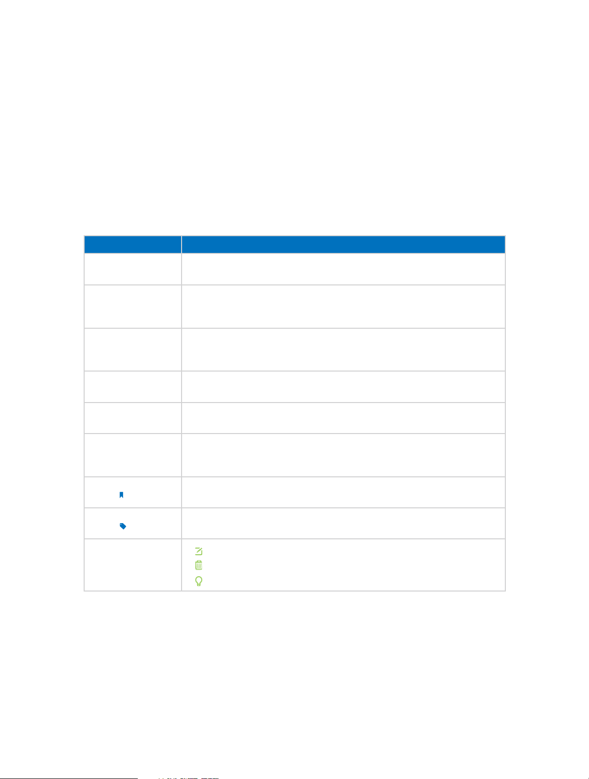
Conventions
In this guide the following conventions are used:
Convention
modem router/
router
parameters
screenshots
Blue Italic
Blue
>
Note:
Tips:
Description
Stands for AC1750 Wireless Dual Band Gigabit ADSL2+ Modem Router
without any explanation.
Parameters provided in the screenshots are just references for setting up the
device, which may differ from the actual situation. You can set the parameters
according to your demand.
The demonstrated screenshots may look a little different from the actual
web page of your device due to the various firmware versions. Please just
configure your product based on the actual web page.
Hyperlinks are in blue italic. You can click to redirect to a website or a specific
section.
Contents to be emphasized and texts on the web page are in blue, including
the menus, items, buttons, etc.
The menu structures to show the path to load the corresponding page. For
example, Advanced > Wireless > MAC Filtering
function page is under the Wireless menu that is located in the Advanced tab.
Ignoring this type of note might result in a malfunction or damage to the
device.
Indicates important information that helps you make better use of your
device.
means the MAC Filtering
symbols on the web
page
click to edit the corresponding entry.
•
•
click to delete the corresponding entry.
•
click to enable or disable the corresponding entry.
1
Page 6

Chapter 1
Get to Know About Your Modem Router
This chapter introduces what the modem router can do and shows its main features
and appearance.
This chapter contains the following sections:
• Product Overview
• Main Features
• Panel Layout
Page 7

Chapter 1
Get to Know About Your Modem Router
1. 1. Product Overview
What This Product Does
TP-LINK’s Archer D7 AC1750 Wireless Dual Band Gigabit ADSL2+ Modem Router is a
combined wired/wireless network connection device with integrated wireless router
and ADSL modem, reducing hassle of configuration and saving space. Featuring a
variety of features and rich functionality, Archer D7 is the perfect hub of your home or
business network.
802.11ac - The Next Generation of Wi-Fi
TP-LINK’s Archer D7 comes with the next generation Wi-Fi standard – 802.11ac,
backward compatible with 802.11n and 3 times faster than wireless N speeds. With
higher power efficiency and robust security, 802.11ac is the perfect way to accelerate
a home multimedia network and solve congestion that multiple devices may cause.
1750Mbps Concurrent Dual Band - More Bandwidth, Less Interference
With 1300Mbps wireless speeds over the crystal clear 5GHz band and 450Mbps over
the 2.4GHz band, Archer D7 offers you the flexibility of two dedicated networks and
ensures amazing wireless performance. Simple tasks such as sending e-mails or web
browsing can be handled by the 2.4GHz band while bandwidth intensive tasks like
online gaming or HD video streaming can be processed by the 5GHz band – all at the
same time.
Full Gigabit Wired Connections - Ultrafast Data Transfer Speeds
With one Gigabit LAN/WAN port and 3 Gigabit LAN ports, the Archer D7 is the ideal
choice for bandwidth heavy users that rely on speedy, reliable connections for
bandwidth intensive work or entertainment such as lag-free conference calls, HD video
streaming or online gaming.
Multifunctional USB Port – Easy Storage and Sharing
Using the Archer D7’s multi-functional USB 2.0 port, you can share a printer with
multiple computers and devices on your network and can also share files & media at
home or via the FTP server while away from home.
Interchangeable LAN/WAN Port - Versatile Connectivity
The Archer D7 supports ADSL or Ethernet WAN connections (EWAN), which allows
users to have the flexibility of different Internet connections among ADSL, cable or
fiber modem using its interchangeable LAN/WAN port. This unique feature makes it
easier when users need to change to fiber or cable services when necessary.
3
Page 8

Chapter 1
Get to Know About Your Modem Router
Guest Network
Guest Network Access provides secure Wi-Fi access for guests sharing your home or
office network in a controlled manner without needing to expose private Wi-Fi access
codes or other personal data.
IPv6 Supported
Archer D7 supports IPv6, which is the foundation of the next generation of the Internet
and enables a range of new services and improved user experience.
1. 2. Main Features
• Complies with IEEE 802.11ac to provide a wireless data rate of up to 450Mbps (2.4GHz)
+ 1300Mbps (5GHz).
• Four 10/100/1000Mbps Auto-Negotiation RJ45 LAN ports (Auto MDI/MDIX), one RJ11
port.
• Provides external splitter.
• Adopts Advanced DMT modulation and demodulation technology.
• Supports bridge mode and Router function.
• Multi-user sharing a high-speed Internet connection.
• Downstream data rates up to 24Mbps, upstream data rates up to 1Mbps.
• Supports long transfers, the max line length can reach to 6.5Km.
• Supports remote configuration and management through SNMP and CWMP.
• Supports PPPoE, which allows connecting to the Internet on demand and
disconnecting from the Internet when idle.
• Provides reliable ESD and surge-protect function with quick response semi-conductive
surge
• protection circuit.
• High speed and asymmetrical data transmit mode, provides safe and exclusive
bandwidth.
• Compatible with all mainstreams DSLAM (CO).
• Provides integrated access of internet and route function which face to SOHO user.
• Real-time Configuration and device monitoring.
• Supports Multiple PVC (Permanent Virtual Circuit).
• Built-in DHCP server.
• Built-in firewall, supporting IP/MAC filter and URL filter.
• Supports Virtual Server, DMZ host and Port Triggering.
• Supports Dynamic DNS, UPnP and Static Routing.
4
Page 9
Chapter 1
Get to Know About Your Modem Router
• Supports system log and flow Statistics.
• Supports firmware upgrade and Web management.
• Provides WPA-PSK/WPA2-PSK data security, TKIP/AES encryption security.
• Provides 64/128-bit WEP encryption security and wireless LAN ACL (Access Control
List).
• Supports USB Storage Sharing, Print Server, FTP Server, Media Server.
• Supports Ethernet WAN (EWAN).
• Supports Bandwidth Control.
• Supports IPv6.
• Supports Guest Network.
1. 3. Panel Layout
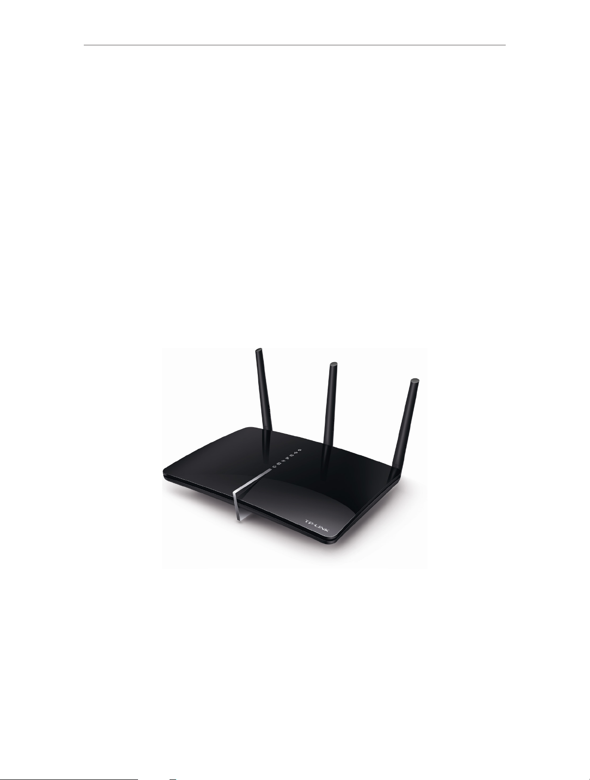
1. 3. 1. Top View
The modem router’s LEDs are located on the top panel (View from top to bottom). You
can check the modem router’s working status by following the LED Explanation table.
5
Page 10
Chapter 1
Get to Know About Your Modem Router
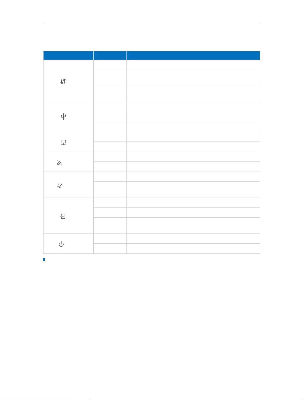
LED Explanation
Name Status
On A WPS synchronization is established.
WPS
USB
LAN
Wireless
Internet
Flashing
Off
On The USB device is identified and ready to use.
Flashing The USB device is being identified.
Off No USB device is plugged into the USB port.
On At least one LAN port is connected.
Off No LAN port is connected.
On The wireless 2.4GHz or 5GHz band is enabled.
Off The wireless function is disabled.
On Internet connection is available.
Off
Indication
A wireless device is trying to connect to the network via WPS.
This process may take up to 3 minutes.
A WPS synchronization has been established for more than 5
minutes or a WPS synchronization failed.
No Internet connection or the modem router is operating in
Bridge mode.
On ADSL line is synchronized and ready to use.
ADSL
Flashing The ADSL negotiation is in progress.
Off
ADSL synchronization failed. Please refer to Note 1 for
troubleshooting.
On Power is on.
Power
Off Power is off.
Note:
1. If the ADSL LED is off, please check your Internet connection first. Refer to Connect Your Modem Router for more
information about how to make Internet connection correctly. If you have already made a right connection,
please contact your ISP to make sure your Internet service is available now.
2. If the Internet LED is off, please check your ADSL LED first. If your ADSL LED is also off, please refer to Note 1. If your
ADSL LED is ON, please check your Internet configuration. You may need to check this part of information with
your ISP and make sure everything have been input correctly.
6
Page 11
Chapter 1
Get to Know About Your Modem Router
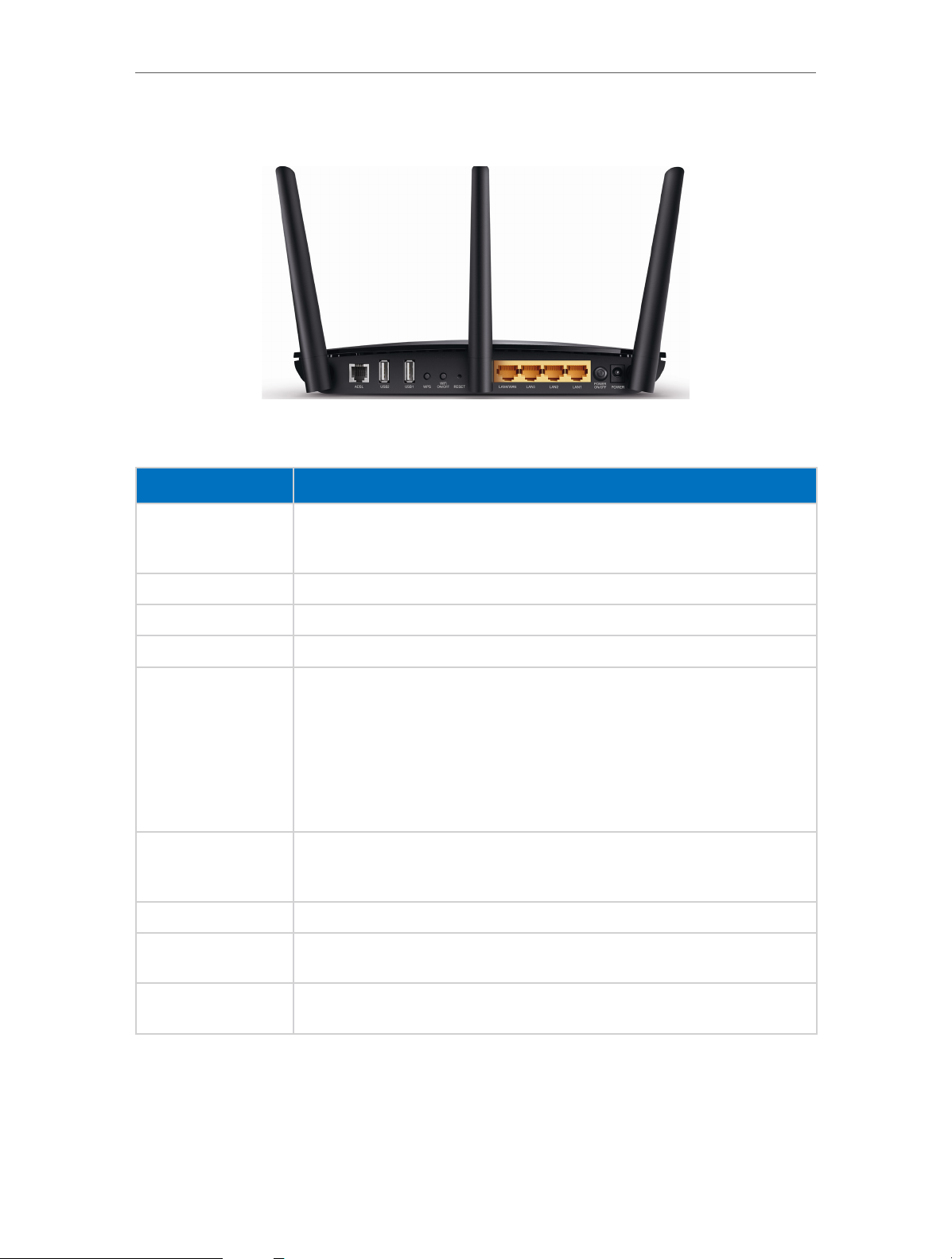
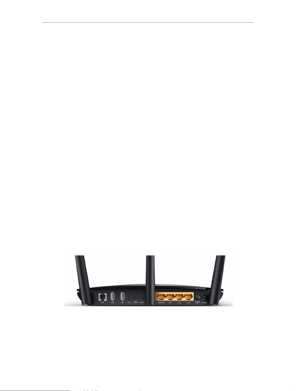
1. 3. 2. The Back Panel
The modem router’s back panel shows the connection ports, buttons and antennas.
Refer to the following for detailed instructions.
Item
For connecting the modem router to the Internet. Connect the port to the
ADSL
USB For connecting to a USB storage device or a USB printer.
WPS The switch for the WPS function.
WiFi ON/OFF For turning on/off the Wi-Fi function.
RESET
LAN1, LAN2, LAN3,
LAN4/WAN
POWER ON/OFF The switch for the power. Press it to power on or off the modem router.
splitter or directly connect the port to the phone jack via a phone cable. For
details, please refer to Connect the Modem Router.
The switch for the RESET function. There are two ways to reset the modem
router’s factory defaults.
Method one: With the modem router powered on, use a pin to press and hold
the RESET button on the rear panel of the modem router for 8 seconds until
all LEDs turn off momentarily, then release the button.
Method two: Log into the web management page of the modem router, and
go to Advanced > System Tools > Backup & Restore, click Factory Restore and
wait until the reset process is complete.
For connecting the modem router to your PC or other Ethernet network
devices. In wireless router mode you will be able to connect to Cable/FTTH/
VDSL/ADSL devices.
Description
POWER
Antennas
For connecting the modem router to power socket via the provided power
adapter.
Used for wireless operation and data transmit. Upright them for the best Wi-Fi
performance.
7
Page 12

Chapter 2
Connect the Hardware
This chapter contains the following sections:
• Position Your Modem Router
• Connect Your Modem Router
Page 13
Chapter 2
Connect the Hardware
2. 1. Position Your Modem Router
With the modem router, you can access your network from anywhere within the
wireless network coverage. However, the wireless signal strength and coverage varies
depending on the actual environment where your modem router is in. Many obstacles
may limit the range of the wireless signal, for example, concrete structures, thickness
and number of walls.
For your security and best Wi-Fi performance, please:
• Do Not locate the modem router in the place where it will be exposed to moisture or
excessive heat.
• Keep away from the strong electromagnetic radiation and the device of
electromagnetic sensitive.
• Place the modem router in a location where it can be connected to the various devices
as well as to a power source.
• Make sure the cables and power cord are safely placed out of the way so they do not
create a tripping hazard.
Tips: The modem router can be placed on a shelf or desktop.
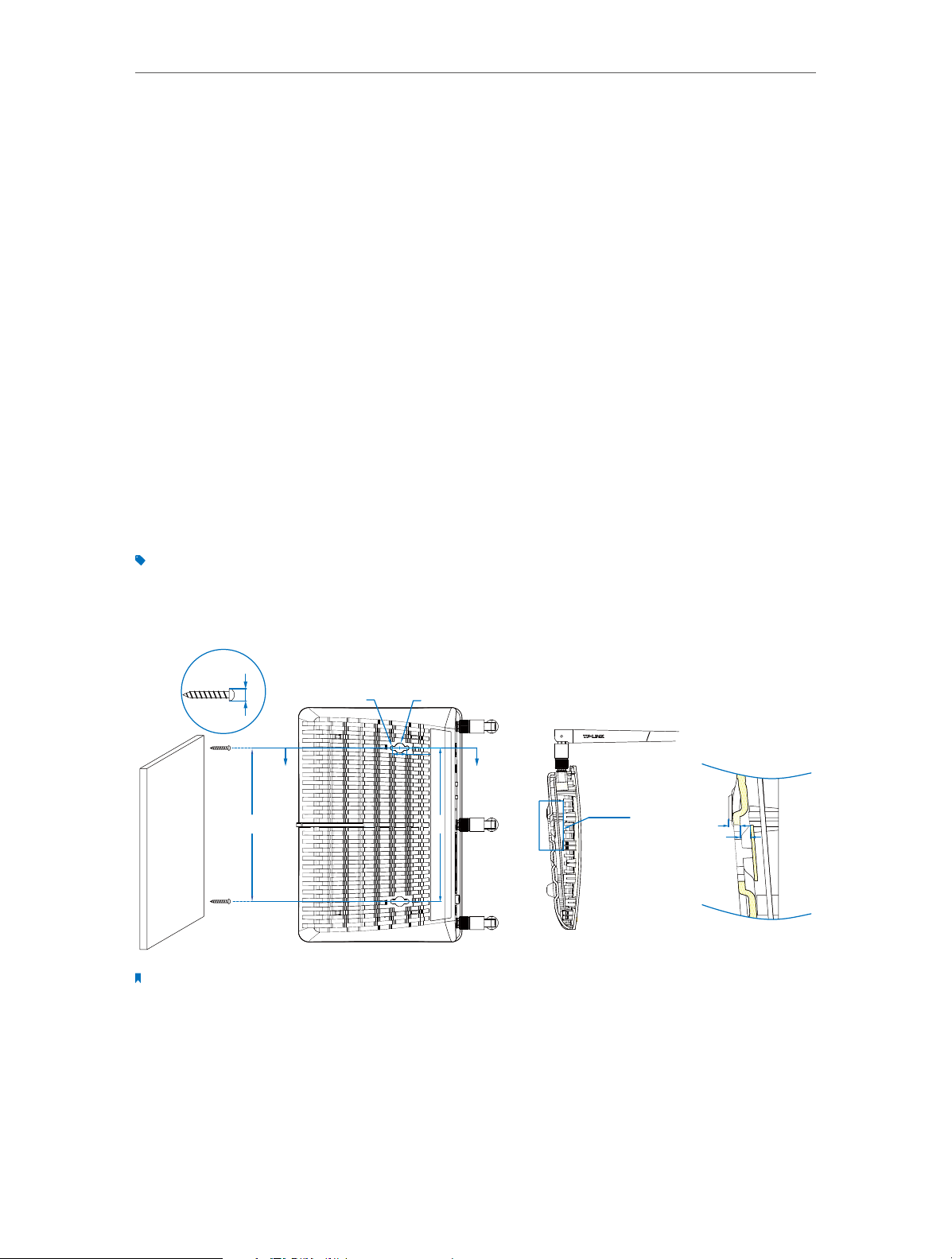
Generally, the modem router is placed on a horizontal surface. The device can also be
mounted on the wall as shown in the following picture.
ØD
Φ4.1
AA
150
Note:
The diameter of the screw is between 4.1mm and 9.6mm, and the distance of two screws is 150mm. The screws that
project from the wall need around 7mm based, and the length of the screw needs to be at least 25mm to withstand
the weight of the product.
Φ9.6
14
150
See detail B
SECTION A-A
4
3.2
detail B
SCALE 3:1
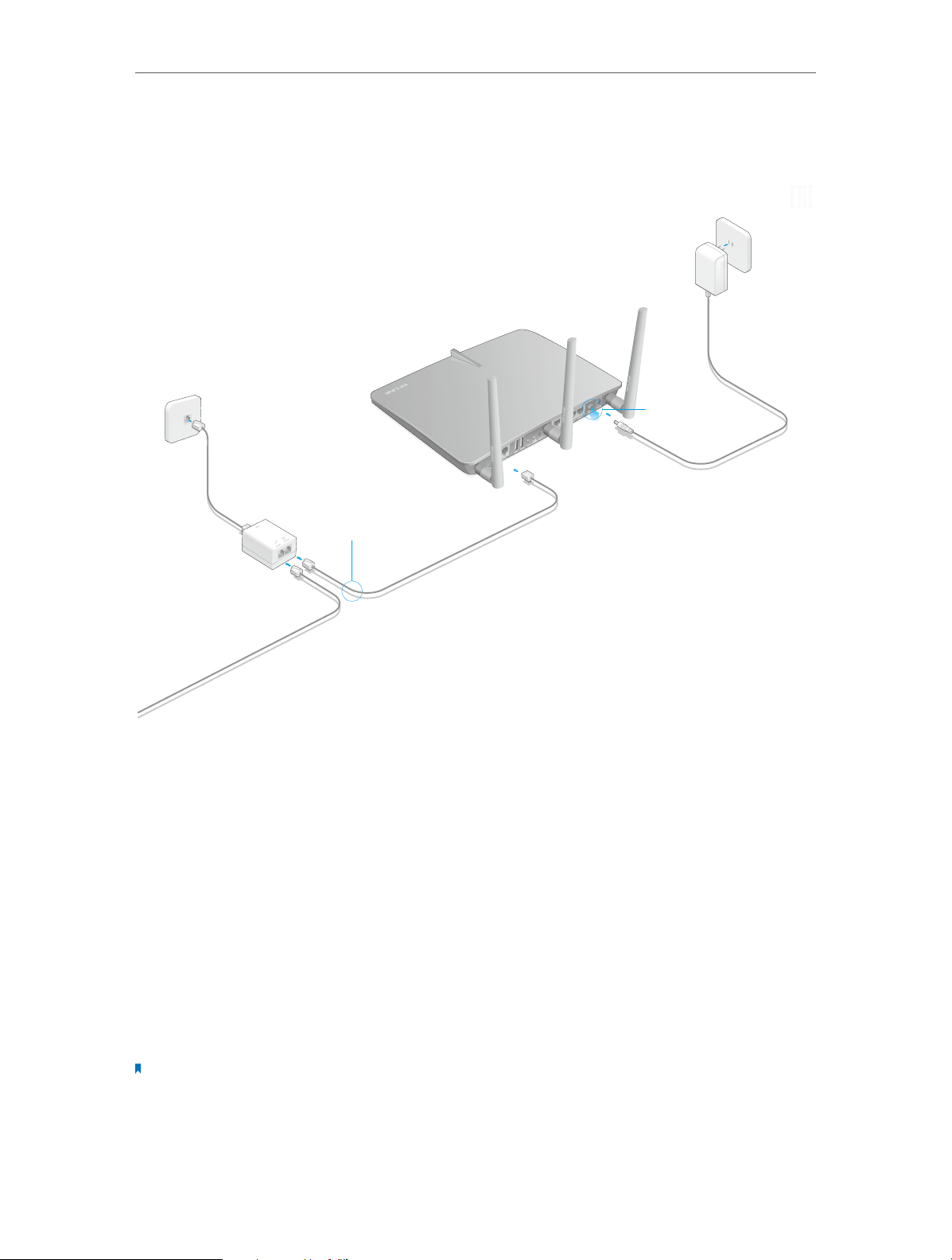
2. 2. Connect Your Modem Router
Follow the steps below to connect your modem router.
9
Page 14
Chapter 2
ADSL Splitter
Phone Jack
Connect to the phone (Optional)
2
Connect the modem router to the
ADSL splitter.
3
Turn on the modem router.
Power Adapter
1 Connect the ADSL splitter
to the phone jack.
Modem Router
Connect the Hardware
1. Connect the ADSL line and power adapter. The electrical outlet shall be installed
near the device and shall be easily accessible
2. Connect your computer to the modem router.
Method 1: Wired
Connect your computer’s Ethernet port to the LAN port on the modem router via the
Ethernet cable.
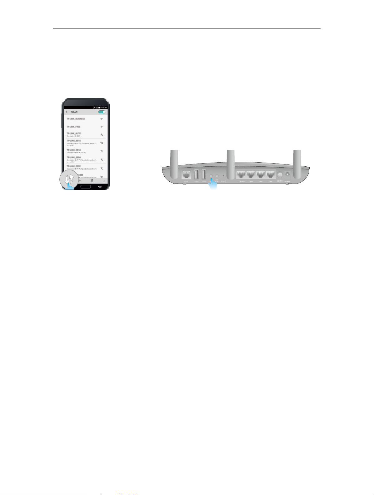
Method 2: Wirelessly
Use the default SSID (Wireless Network Name) and Wireless Password printed on the
product label of the modem router to connect wirelessly.
Method 3: Use the WPS button
Wireless devices that support WPS, including Android phones, tablets, most USB
network cards, can be connected to your router through this method. (WPS is not
supported by IOS devices.)
Note:
The WPS function cannot be configured if the wireless function of the router is disabled. Also, the WPS function will
be disabled if your wireless encryption is WEP. Please make sure the wireless function is enabled and is configured
with the appropriate encryption before configuring the WPS.
1 ) Tab the WPS icon on the device’s screen.
10
Page 15
Chapter 2
Connect the Hardware
2 ) Immediately press the WPS button on your modem router.
3 ) The WPS LED flashes for about 3 minutes during the WPS process.
4 ) When the WPS LED is on, the client device has successfully connected to the
modem router.
11
Page 16

Chapter 3
Log into Your Modem Router
Page 17
Chapter 3
Log into Your Modem Router
With a Web-based utility, it is easy to configure and manage the modem router. The
Web-based utility can be used on any Windows, Macintosh or UNIX OS with a Web
browser, such as Microsoft Internet Explorer, Mozilla Firefox or Apple Safari.
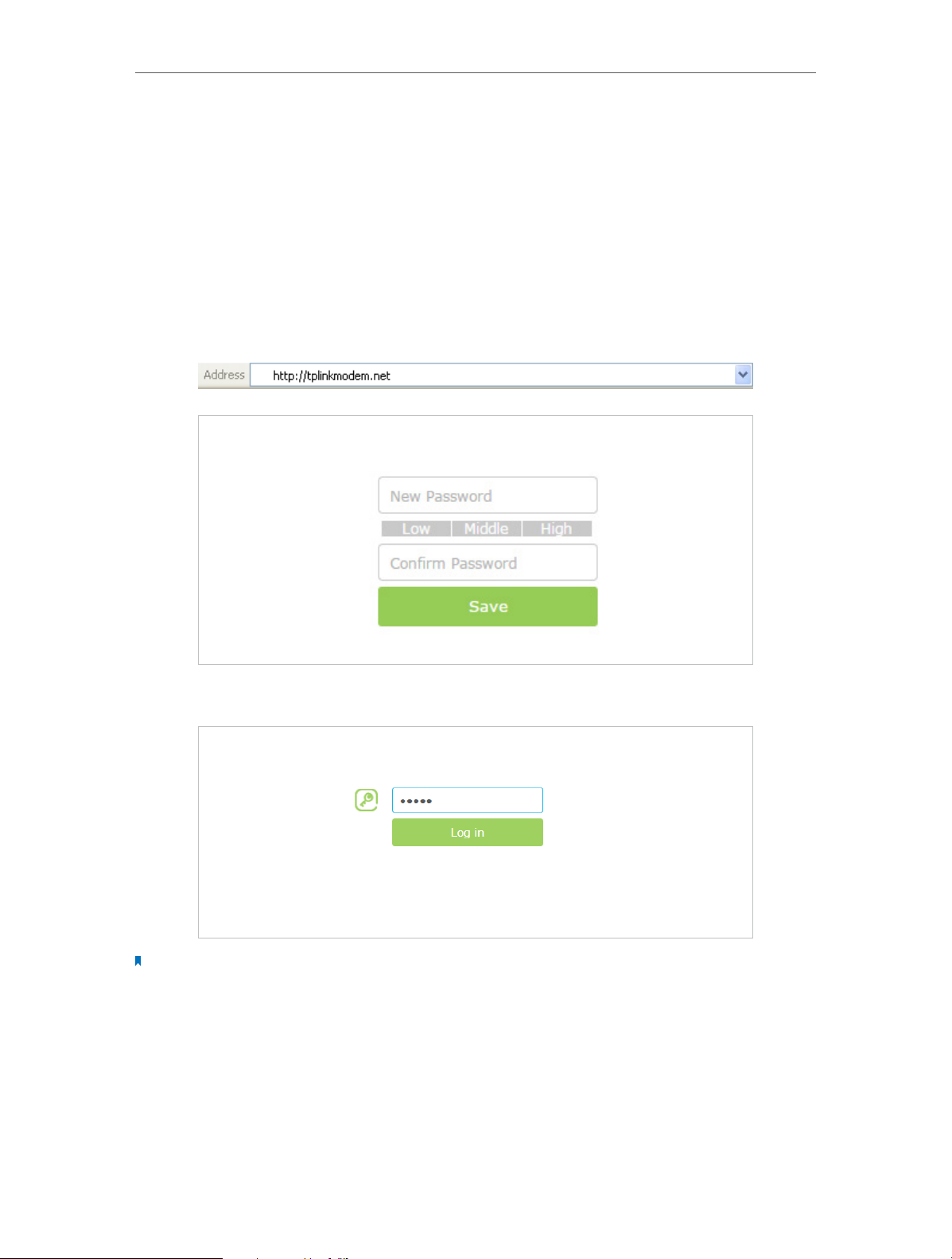
Follow the steps below to log into your modem router.
1. If the TCP/IP Protocol on your computer is set to the static (fixed) IP address, you
need to change it to obtain an IP address automatically.
2. Launch a web browser and type in http://tplinkmodem.net or http://192.168.1.1. Set
a strong password using 1-15 characters and click Save.
3. Enter the password you set and click Login.
Note: For subsequent logins, you only need to enter the password that you have set to log in.
13
Page 18

Chapter 4
Set Up Internet Connections
This chapter introduces how to connect your modem router to the Internet. The
modem router is equipped with a web-based Quick Setup wizard. It has many ISP
information built in, automates many of the steps and verifies that those steps have
been successfully completed. Furthermore, you can also set up an IPv6 connection if
your ISP provided IPv6 service.
This chapter includes the following sections:
• Use Quick Setup Wizard
• Manually Set up an Internet Connection
• Set up an IPv6 Connection
• Test Internet Connectivity
Page 19
Chapter 4
Set Up Internet Connections
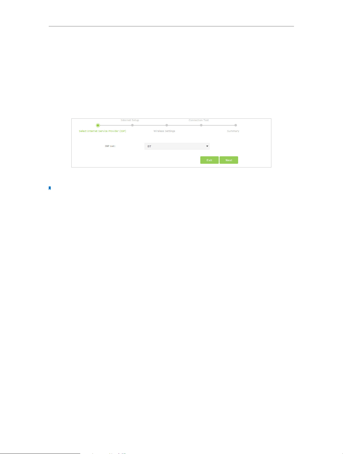
4. 1. Use Quick Setup Wizard
To set up your modem router with several easy steps quickly:
1. Visit http://tplinkmodem.net, and log in with the password you set for the modem
router.
2. Click Quick Setup, select your ISP from the dropdown list or select Other if you can’t
find your ISP, then click Next.
3. Follow the on-screen instructions to complete the setup.
Note:
1. During the quick setup process, you can change the preset wireless network name (SSID) and wireless password.
Once done, all your wireless devices must use the new SSID and password to connect to the modem router.
2. The modem router supports two operation modes, DSL Modem Router Mode and Wireless Router mode. If you
already have a modem or your Internet comes via an Ethernet cable from the wall, you can set up the modem
router as a regular wireless router to share the Internet. Refer to Appendix B: Troubleshooting for details.
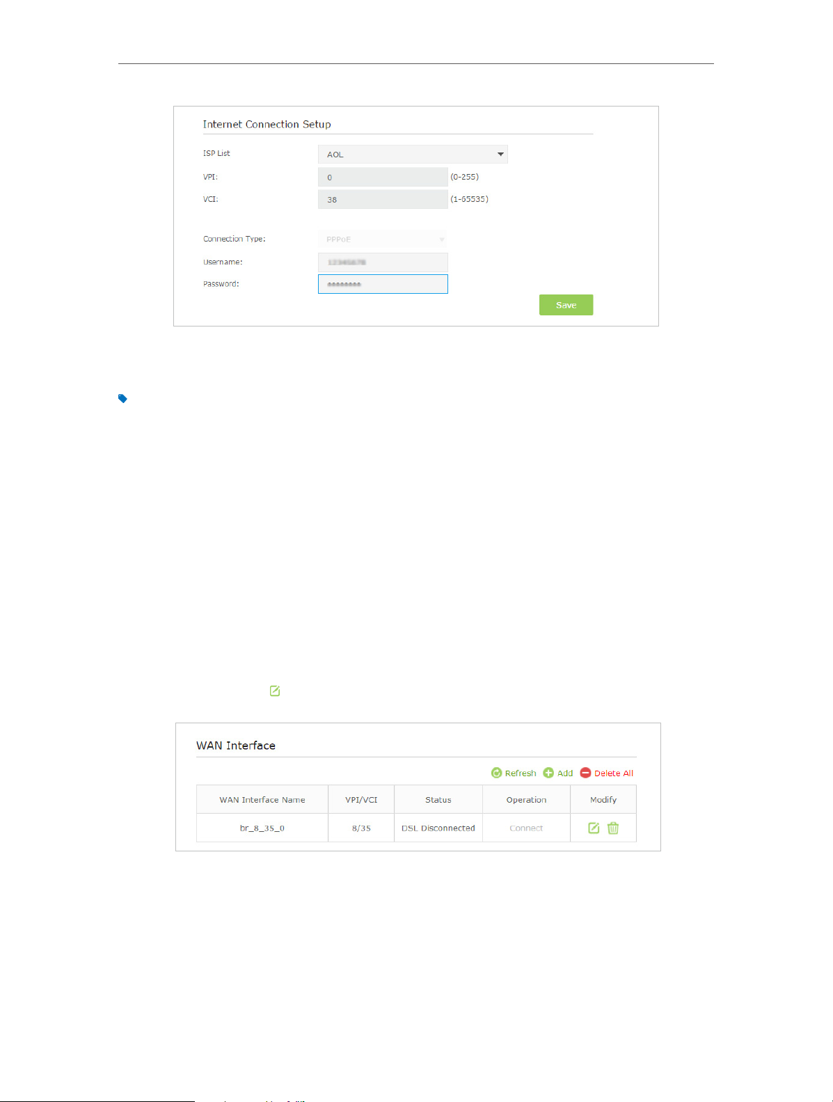
4. 2. Manually Set up an Internet Connection
To manually add an Internet connection without following the instructions of the Quick
Setup wizard:
1. Visit http://tplinkmodem.net, and log in with the password you set for the modem
router.
2. Go to Basic > Internet page. Select your ISP, and the VPI and VCI values will
be automatically filled in. Enter the information provided by your ISP for the
Connection Type. If you can’t find your ISP in the ISP List, select Other and then
enter the information provided by your ISP.
15
Page 20
Chapter 4
Set Up Internet Connections
3. Click Save to make the settings effective and you can refer to Test Internet Connectivity
to test the Internet connection.
Tips: You can view and edit all Internet connections on Advanced > Network > Internet page.
4. 3. Set up an IPv6 Connection
If the DSL line your ISP provided also supports IPv6 connection and your ISP has
provided some detailed IPv6 parameters, you can configure the modem router to
permit IPv6 connection.
Follow the steps below to set up an IPv6 connection.
1. Configure the WAN settings.
1 ) Visit http://tplinkmodem.net, and log in with the password you set for the
modem router.
2 ) Go to Advanced > Network > Internet page. Select your WAN Interface Name
and click the
(Edit) icon.
3 ) Scroll down to configure the IPv6 parameters.
16
Page 21
Chapter 4
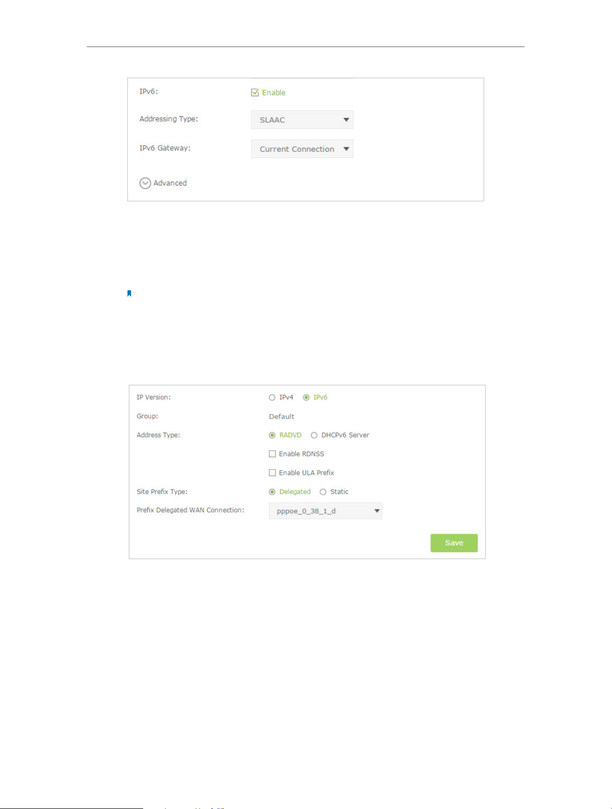
Select the checkbox to enable IPv6 feature.
Addressing Type: Consult your ISP for the addressing type, DHCPv6 or SLAAC.
SLAAC is the most commonly used addressing type.
IPv6 Gateway: Keep the default setting as Current Connection.
Note: If your ISP has provided the IPv6 address, click Advanced to reveal more settings. Check to use
IPv6 specified by ISP and enter the parameters provided by your ISP.
4 ) Click OK to make the settings effective.
Set Up Internet Connections
2. Configure the IPv6 LAN settings. Go to Advanced > Network > LAN Settings page.
Select IPv6 to configure IPv6 LAN parameters.
1 ) Select the Prefix Delegated WAN Connection, the IPv6 connection you just set
up, from the drop-down list.
2 ) Leave the rest of the settings as default.
3 ) Click Save to make the settings effective.
3. Done. IPv6 service is available for your network.
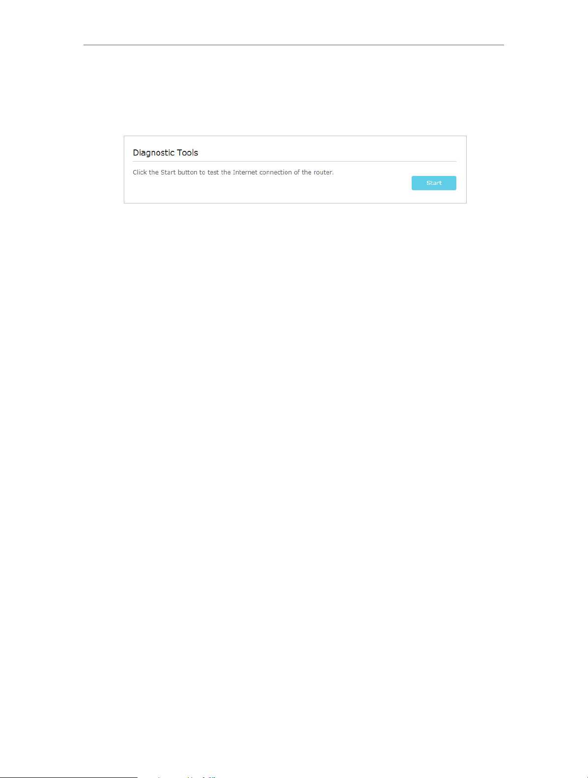
4. 4. Test Internet Connectivity
After setting up the Internet connection, you need to know the Internet connectivity.
The modem router provides a diagnostic tool to help you locate the malfunction.
17
Page 22
Chapter 4
Set Up Internet Connections
1. Visit http://tplinkmodem.net, and log in with the password you set for the modem
router.
2. Go to Advanced > System Tools > Diagnostics page.
3. Click Start to test the Internet connectivity and you will see the test result in the
gray box.
18
Page 23

Chapter 5
Bandwidth Control
The Bandwidth Control feature is used to fully utilize your limited bandwidth and
optimize the load respectively. With this feature enabled, you can assign a specific
minimum or maximum bandwidth for each computer, thus minimizing the impact
caused when the connection is under heavy load.
Page 24
Chapter 5
Bandwidth Control
I want to:
Tips:
How can I
do that?
Use an independent bandwidth and enjoy a good Internet
experience without being affected by other users who are
sharing the same router.
For example, my roommate and I share 512Kbps Upstream
Bandwidth and 8Mbps Downstream Bandwidth via this router,
she likes to watch live show and play online games, which may
take up much bandwidth. I don’t want to be affected, so we
agree to equally distribute the bandwidth. Our IP addresses are
192.168.1.101 and 192.168.1.110.
To use the bandwidth control feature, you’d better set static
IP Address on each computer to be controlled or configure
Address reservation on the modem router in order to manage
easily. About how to configure address reservation, please refer
to Reserve LAN IP Addresses.
1. Visit http://tplinkmodem.net, and log in with the password
you set for the modem router.
2. Go to Advanced > Bandwidth Control page.
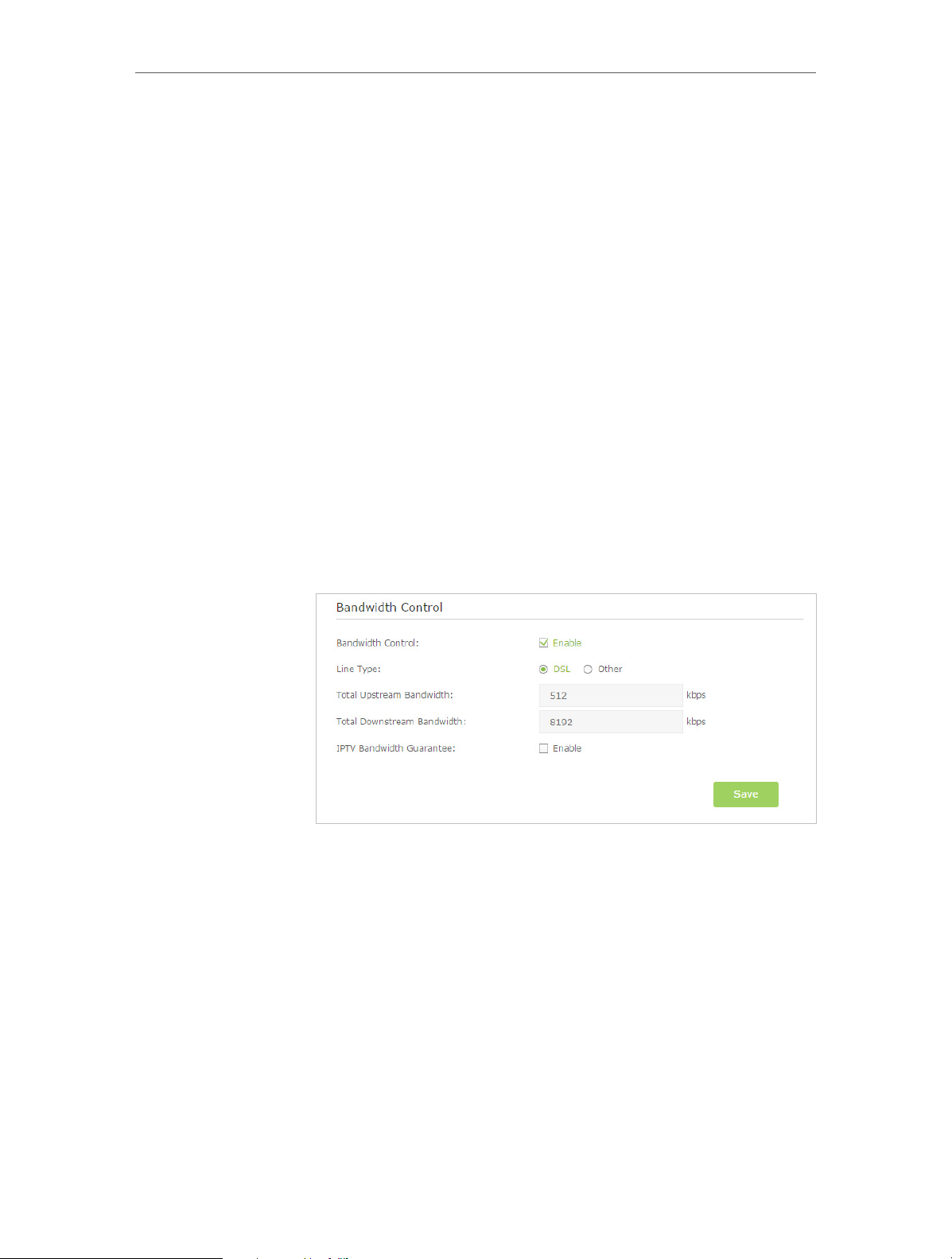
3. Enable Bandwidth Control, choose DSL on the line type. If
you don’t know how to choose the line type, please contact
your ISP which line type you have access.
4. Enter the Total Upstream Bandwidth and the Total Downstream
Bandwidth given by your ISP. (1Mbps=1024Kbps). Click Save
to save the settings.
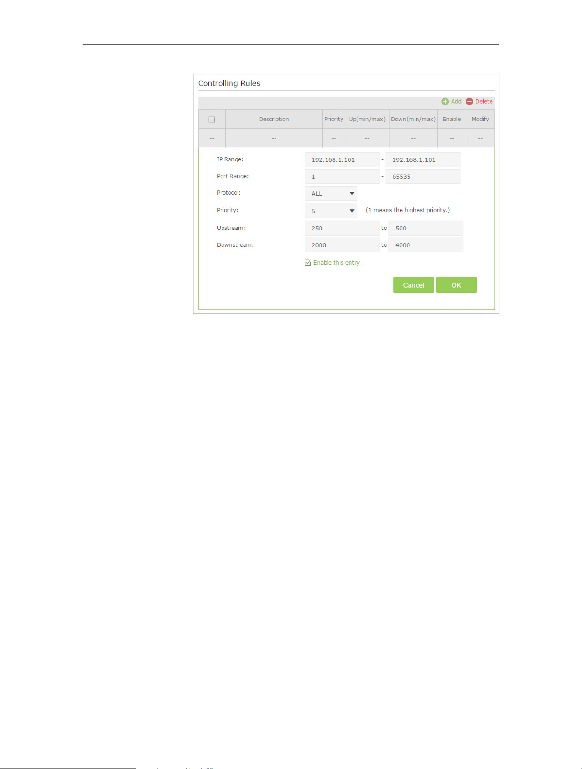
5. Click Add to add controlling rules for each computer
respectively.
20
Page 25
Chapter 5
Bandwidth Control
1 ) IP Range: Enter the IP address. The field can be single IP
address or IP address range according to your demands.
When you configure the single IP address, the computer
with this IP address will get independent given
bandwidth. When you configure the IP address range, all
computers in the range will share the given bandwidth.
2 ) Port Range: Keep the default settings. The default port
range of TCP protocol or UDP protocol is from 1 to 65535.
3 ) Protocol: Keep the default setting. Or you can choose the
TCP protocol or UDP protocol or both of them.
4 ) Priority: Keep the default setting. You can change the
value if you want to first guarantee the bandwidth for
one computer. The smaller value has the higher priority.
5 ) Upstream/Downstream: Enter the bandwidth according
to your division.
6 ) Check to enable this entry and click OK to save the
settings.
6. Follow the steps above to add a rule for the other computer.
And then you will get the following table.
21
Page 26

Chapter 5
Bandwidth Control
Done!
Now you and your roommate have an independent bandwidth.
22
Page 27

Chapter 6
Network Security
This chapter guides you on how to protect your home network from unauthorized
users by implementing these three network security functions. You can block or allow
specific client devices to access your wireless network using MAC Filtering, or using
Access Control for wired and wireless networks, or you can prevent ARP spoofing and
ARP attacks using IP & MAC Binding.
• MAC Filtering
• Access Control
• IP & MAC Binding
Page 28
Chapter 6
Network Security
6. 1. MAC Filtering
This function exploits the uniqueness of the MAC (Medium Access Control) address,
a unique 12-digit hexadecimal address (for example, D8:5D:4C:B4:46:EA) of every
network device, to determine if the device can or cannot access your wireless network.
I want to:
How can I
do that?
Prevent unauthorized users from accessing my wireless network
by utilizing the network device’s MAC address and IP address.
For example, I have a computer that is connected to my wireless
network. Now, an unknown device (an intruder) is also using my
wireless network, which affects my Internet speed. I would like
to control my wireless network with the following capabilities:
• My computer is always allowed to access the wireless network.
• The unknown device is not allowed to access the wireless
network.
• I don’t have to keep changing my wireless password as often.
1. Visit http://tplinkmodem.net, and log in with the password
you set for the router.
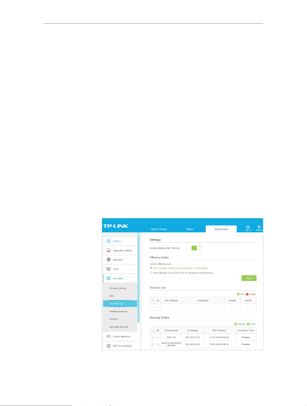
2. Go to Advanced > Wireless > MAC Filtering and enable
Wireless MAC Filtering.
3. Select the filtering rule to either block (recommended) or
allow the device(s) in the list.
24
Page 29
Chapter 6
To block specific device(s)
1 ) Select Block wireless access from the devices in the list
below and click Save.
2 ) Select the device(s) to be blocked in the Devices Online
table.
3 ) Click Block above the Devices Online table. The selected
devices will be added to Devices List automatically.
To allow specific device(s)
1 ) Select Allow wireless access only from the devices in the
list below and click Save.
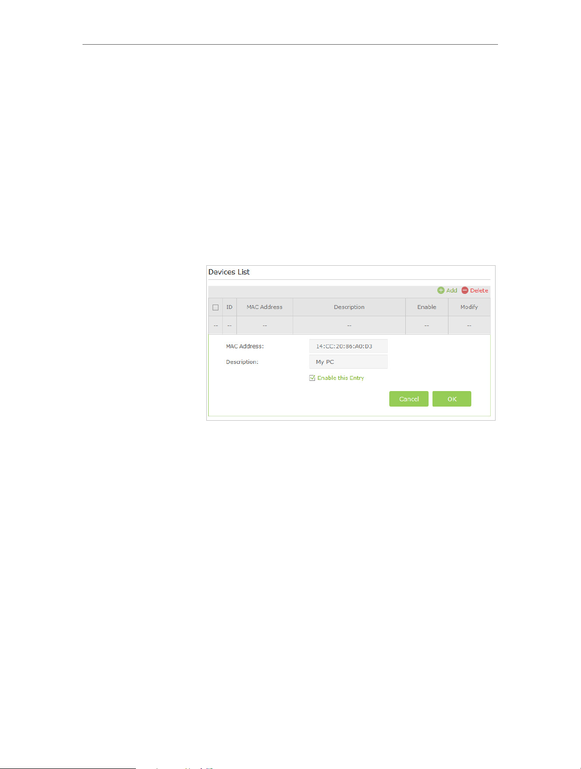
2 ) Click Add.
Network Security
3 ) Enter the MAC Address (You can copy and paste the MAC
Address from Devices Online list if the device is connected
to your wireless network) and enter the Description of
the device.
4 ) Select the checkbox to enable this entry, and click OK.
Done!
Now MAC Filtering is implemented to protect your wireless
network.
6. 2. Access Control
Access Control is used to block or allow specific client devices to access your network
(via wired or wireless) based on a list of blocked devices (Blacklist) or a list of allowed
devices (Whitelist).
I want to:
Block or allow specific client devices to access my network (via
wired or wireless).
25
Page 30
Chapter 6
Network Security
How can I
do that?
1. Visit http://tplinkmodem.net, and log in with the password
you set for the router.
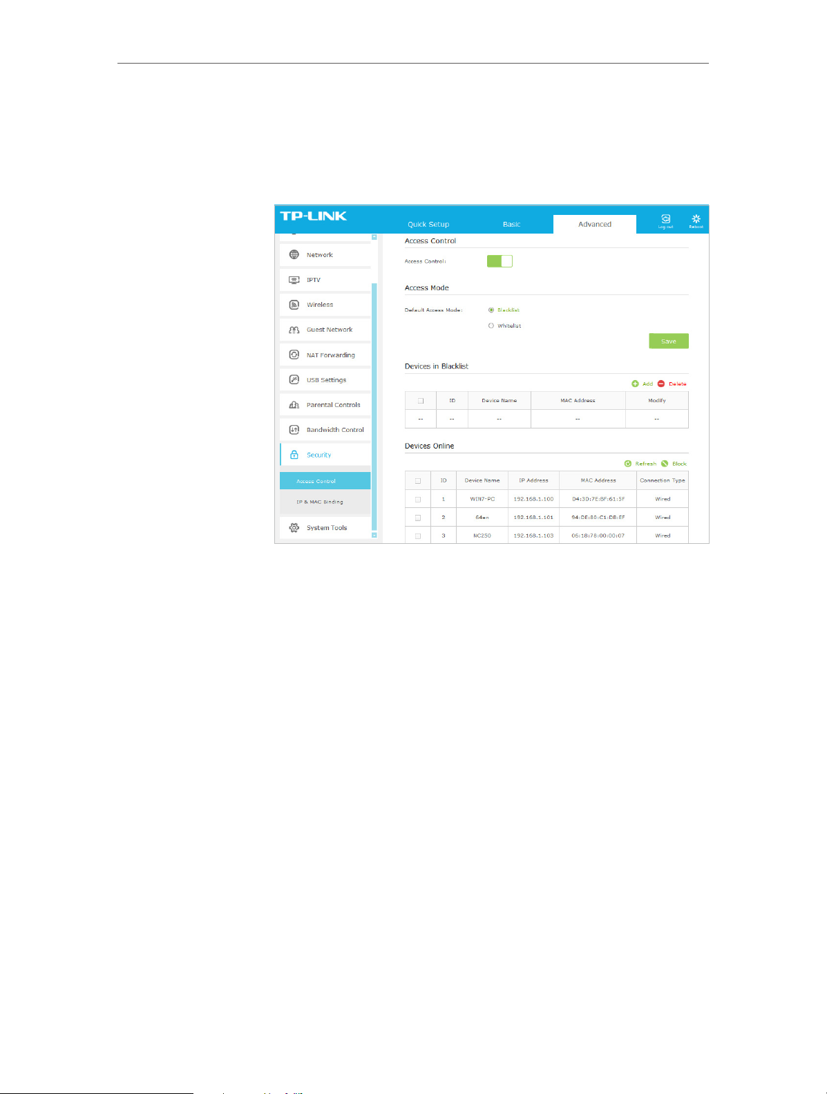
2. Go to Advanced > Security > Access Control and enable
Access Control.
3. Select the access mode to either block (recommended) or
allow the device(s) in the list.
To block specific device(s)
1 ) Select Blacklist and click Save.
2 ) Select the device(s) to be blocked in the Devices Online
table.
3 ) Click Block above the Devices Online table. The selected
devices will be added to Devices in Blacklist automatically.
To allow specific device(s)
1 ) Select Whitelist and click Save.
2 ) Click Add.
26
Page 31

Chapter 6
3 ) Enter the Device Name and MAC Address (You can copy
and paste the information from Devices Online table if
the device is connected to your network).
4 ) Click OK.
Network Security
Done!
Now you can block or allow specific client devices to access your
network (via wired or wireless) using the Blacklist or Whitelist.
6. 3. IP & MAC Binding
IP & MAC Binding, namely, ARP (Address Resolution Protocol) Binding, is used to bind
network device’s IP address to its MAC address. This will prevent ARP spoofing and
other ARP attacks by denying network access to an device with matching IP address in
the Binding list, but unrecognized MAC address.
I want to:
How can I
do that?
Prevent ARP spoofing and ARP attacks.
1. Visit http://tplinkmodem.net, and log in with the password
you set for the router.
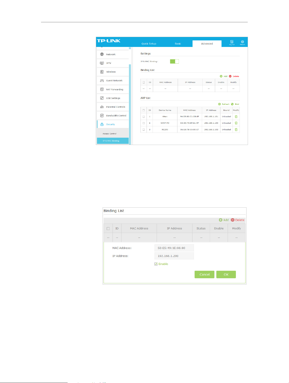
2. Go to Advanced > Security > IP & MAC Binding and enable IP
& MAC Binding.
27
Page 32
Chapter 6
Network Security
3. Bind your device(s) according to your needs.
To bind the connected device(s)
1 ) Select the device(s) to be bound in the ARP List.
2 ) Click Bind to add to the Binding List.
To bind the unconnected device
1 ) Click Add.
2 ) Enter the MAC address and IP address that you want to
bind.
Done!
3 ) Select the checkbox to enable the entry and click OK.
Now you don’t need to worry about ARP spoofing and ARP
attacks.
28
Page 33

Chapter 7
IPTV
IPTV is the abbreviation of Internet Protocol Television. The service can only be delivered
through the Internet, and our modem router provides a specific LAN port for IPTV.
By automatically seperating IPTV from Internet surfing, we guarantee you a high quality
of video streaming and a high speed of Internet surfing.
Page 34

Chapter 7
IPTV
I want to:
How can I
do that?
Configure the modem router to enable Internet Protocol
Television (IPTV) Services.
For example, I already bought IPTV service, but this service can
only be delivered through the Internet. Therefore, I need to
configure my modem router first.
1. Visit http://tplinkmodem.net, and log in with the password
you set for the router.
2. Go to Advanced > IPTV to open the configuration page.
Done!
3. Click Enable IPTV to enable this function.
4. Specify a LAN port for IPTV connection and connect the set-
top box to this port.
5. Fill in PVC parameters (VPI and VCI). These parameters are
provided by your IPTV service provider.
6. Click Save to make the settings effective.
Configurations needed on modem router is done now! You may
need other configurations on your set-top box before enjoying
your TV.
30
Page 35

Chapter 8
USB Settings
This chapter describes how to share and access USB devices connected to the modem
router among different clients.
The modem router only supports USB external flash drives, hard drives and USB printers,
and does not support USB 3G/4G modems.
This chapter contains the following sections:
• Local Storage Sharing
• Remote Access via FTP Serverr
• Media Sharing
• Printer Sharing
Page 36

Chapter 8
USB Settings
8. 1. Local Storage Sharing
Share your USB storage devices with different users on the network.
8. 1. 1. Access the USB disk
1. Connect Your USB Disk
Insert your USB storage device into the modem router’s USB port directly or using
a USB cable. Wait several seconds until the USB LED becomes solid on.
Tips:
• If you use USB hubs, make sure no more than 4 devices are connected to the modem router.
• If the USB storage device requires using bundled external power, make sure the external power has been
connected.
• If you use a USB hard drive, make sure its file system is FAT32 or NTFS.
• Before you physically disconnect a USB device from the modem router, safely remove it to avoid data
damage: Go to Advanced > USB Settings > Device Settings and click
2. Access Your USB Disk
.
By default all the network clients can access all folders on your USB disk. Refer to
the following table for access instructions. You can also customize your sharing
content and set a sharing account by referring to Customize Your Settings.
32
Page 37
Chapter 8
USB Settings
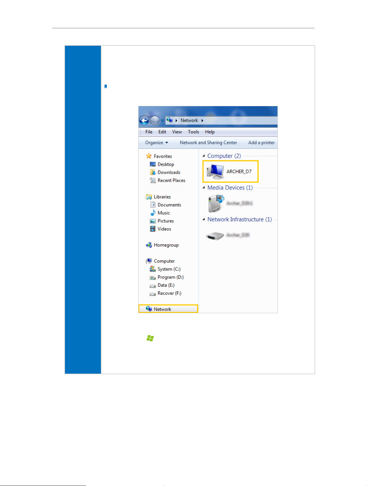
¾ Method 1:
Go to Computer > Network, then click the Network Server Name (ARCHER _D7 by
default) in the Computer section.
Note:
Here takes Windows 7 as an example.
Windows
computer
¾ Method 2:
1. Press Start (
)+ R on the keyboard (or select Start > Run)
2. Type the server address \\tplinkmodem.net or ftp://tplinkmodem.net in the
dialog box
3. Click OKs
33
Page 38

Chapter 8
1. Select Go > Connect to Server
USB Settings
2. Type the server address smb://tplinkmodem.net or ftp://
3. When prompted, select the Guest radio box
Mac
pad
Tips:
You can also access your USB disk by using your Network/Media Server Name as the server address. Refer to To
Customize the Address of the USB Disk to learn more.
4. Click Connect
Note:
If you have set up a username and a password to deny anonymous access to the USB disks,
you should select the Registered User radio box. To learn how to set up an account for the
access, refer to To Set up Authentication for Data Security.
Use a third-party app for network files management.
tplinkmodem.net
8. 1. 2. Customize Your Settings
¾ To Only Share Specific Content
By default, Share All is enabled so all content on the USB disk is shared. If you want to
only share specific folders, follow the steps below:
1. Visit http://tplinkmodem.net, then log in with the password you set for the modem
router.
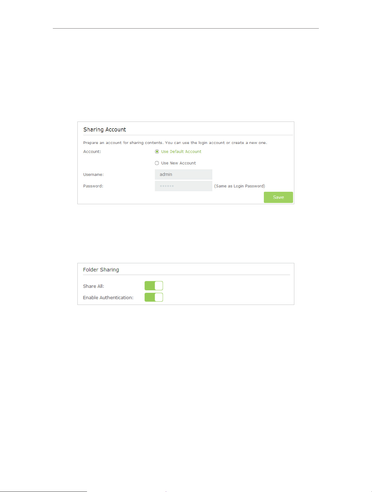
2. Select Basic > USB Settings > Sharing Access. Focus on the Folder Sharing section.
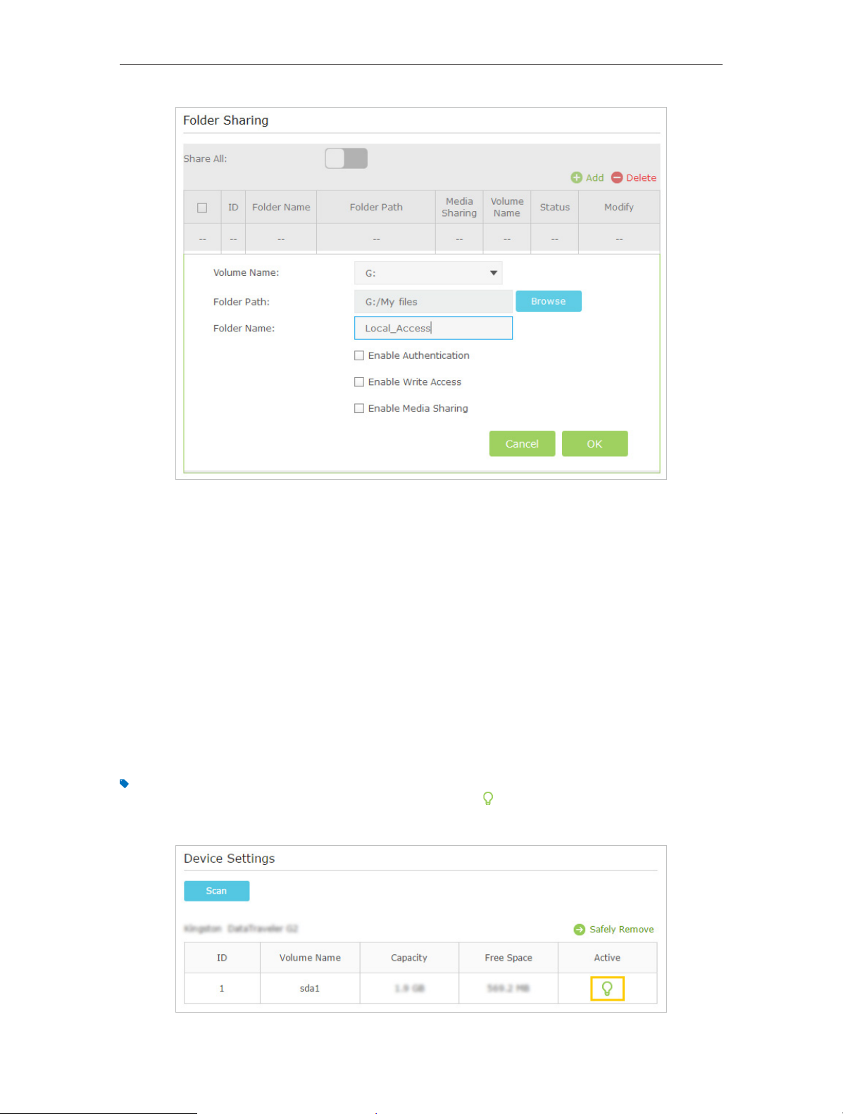
Click the button to disable Share All, then click Add to add a new sharing folder.
34
Page 39
Chapter 8
USB Settings
3. Select the Volume Name and Folder Path, then enter a Folder Name as you like.
4. Decide the way you share the folder:
• Enable Authentication: Tick to enable authentication for this folder sharing,
and you will be required to use a username and password to access the USB
disk. Refer to To Set up Authentication for Data Security to learn more.
• Enable Write Access: If you tick this check box, network clients can modify this
folder.
• Enable Media Sharing: Tick to enable media sharing for this folder, and you can
view photos, play music and watch movies stored on the USB disk directly from
DLNA-supported devices. Click Media Sharing to learn more.
5. Click OK.
Tips:
The modem router can share eight volumes at most. You can click
volume you do not need to share.
on the page to detach the corresponding
35
Page 40
Chapter 8
USB Settings
¾ To Set up Authentication for Data Security
If you enable Authentication, network clients will be required to enter the username
and password you set when accessing the USB disk.
1. Visit http://tplinkmodem.net, then log in with the password you set for the modem
router.
2. Select Advanced > USB Settings > Sharing Access.
3. Choose to use the default Account (admin) or use a new account and click Save.
4. Enable Authentication to apply the account you just set.
• If you leave Share All enabled, click the button to enable Authentication for all
folders.
• If Share All is disabled, enable Authentication for specific folders.
36
Page 41

Chapter 8
USB Settings
¾ To Customize the Address of the USB Disk
You can customize the server name and use the name to access your USB disk.
1. Visit http://tplinkmodem.net, then log in with the password you set for the modem
router.
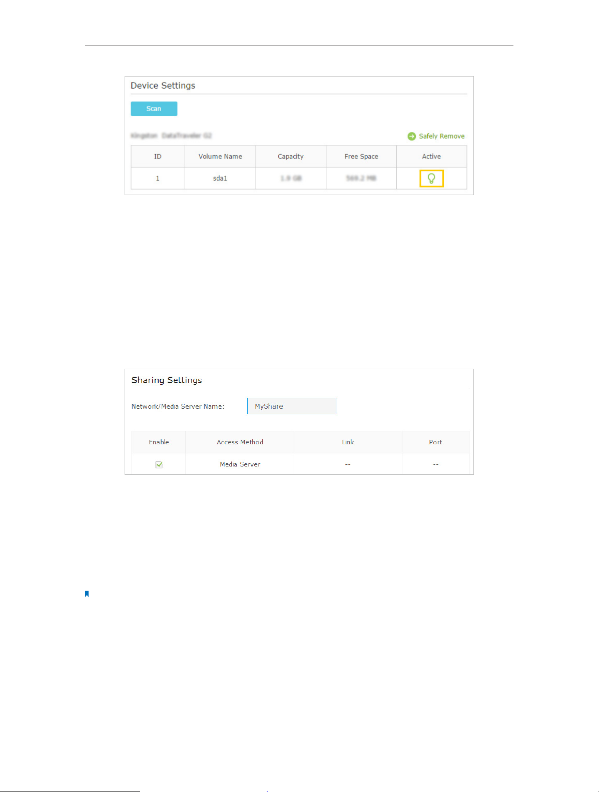
2. Select Advanced > USB Settings > Sharing Access.
3. Make sure Network Neighborhood is ticked, and enter a Network/Media Server
Name as you like, such as MyShare, then click Save.
37
Page 42

Chapter 8
USB Settings
4. Now you can access the USB disk by visiting \\MyShare (for Windows) or smb://
MyShare (for Mac).
8. 2. Remote Access via FTP Server
You can access your USB disk outside the local area network.
For example:
• Share photos and other large files with your friends without logging in to (and paying
for) a photo-sharing site or email system.
• Get a safe backup for the materials for a presentation.
• Remove the files on your camera’s memory card from time to time during the journey.
Note:
If your ISP assigns a private WAN IP address (such as 192.168.x.x or 10.x.x.x), you cannot use this feature because
private addresses are not routed on the Internet.
8. 2. 1. Access the USB disk
1. Connect Your USB Disk
Insert your USB storage device into the modem router’s USB port directly or using
a USB cable. Wait several seconds until the USB LED becomes solid on.
Note:
• If you use USB hubs, make sure no more than 4 devices are connected to the modem router.
• If the USB storage device requires using bundled external power, make sure the external power has been
connected.
• If you use a USB hard drive, make sure its file system is FAT32 or NTFS.
• Before you physically disconnect a USB device from the modem router, safely remove it to avoid data
damage: Select Advanced > USB Settings > Device Settings and click
2. Enable Authentication for Data Security
It is strongly recommended that you set and apply a sharing account for data
security.
1 ) Visit http://tplinkmodem.net, then log in with the password you set for the
modem router.
2 ) Select Advanced > USB Settings > Sharing Access.
3 ) Choose to use the default Account (admin) or use a new account and click Save.
.
38
Page 43

Chapter 8
USB Settings
4 ) Enable Authentication to apply the sharing account.
• If you leave Share All enabled, click the button to enable Authentication for all
folders.
• If Share All is disabled, enable Authentication for specific folders.
3. Enable the FTP(via Internet)
Select the check box to enable FTP(via Internet), then click Save.
39
Page 44

Chapter 8
4. Access Your USB Disk via Internet
Now different clients with Internet connection can access the USB disk:
USB Settings
• To download, open a web browser and type the server address ftp://<WAN IP
address of the modem router>:<port number> (such as ftp:// 59.40.2.243:21)
Computer
Pad
Tips:
Click Set Up a Dynamic DNS Service Account to learn how to set up a domain name for you modem router.
or ftp://<domain name of the modem router>:<port number> (such as ftp ://
MyDomainName:21) in the address bar, then press Enter on the keyboard.
• To upload, use a third-party app for network files management.
• Use a third-party app for network files management.
8. 2. 2. Customize Your Settings
¾ To Only Share Specific Content
By default, Share All is enabled so all content on the USB disk is shared. If you want to
only share specific folders, follow the steps below:
1. Visit http://tplinkmodem.net, then log in with the password you set for the modem
router.
2. Select Basic > USB Settings > Sharing Access. Focus on the section of Folder Sharing.
Click the button to disable Share All, then click Add to add a new sharing folder.
40
Page 45

Chapter 8
USB Settings
3. Select the Volume Name and Folder Path, then specify the Folder Name as you like.
4. Tick Enable Authentication. If you allow network clients to modify this folder, tick
Enable Write Access.
5. Click OK.
Tips:
The modem router can share eight volumes at most. You can click
volume you do not need to share.
on the page to detach the corresponding
8. 3. Media Sharing
The feature of Media Sharing allows you to view photos, play music and watch movies
stored on the USB disk directly from DLNA-supported devices, such as your computer,
pad and PS2/3/4.
41
Page 46

Chapter 8
USB Settings
8. 3. 1. Access the USB disk
1. Connect Your USB Disk
Insert your USB storage device into the modem router’s USB port directly or using
a USB cable. Wait several seconds until the USB LED becomes solid on.
Note:
• If you use USB hubs, make sure no more than 4 devices are connected to the modem router.
• If the USB storage device requires using bundled external power, make sure the external power has been
connected.
• If you use a USB hard drive, make sure its file system is FAT32 or NTFS.
• Before you physically disconnect a USB device from the modem router, safely remove it to avoid data
damage: Go to Advanced > USB Settings > Device Settings and click
2. Access the Media Files on Your USB Disk
Now the DLNA-supported devices (such as your computer and pad) connected to
the modem router can detect and play the media files on the USB disks.
• Go to Computer > Network, then click the Media Server Name (Archer_D7 by
default) in the Media Devices section.
.
Windows
computer
Note:
Here takes Windows 7 as an example.
42
Page 47

Chapter 8
USB Settings
Pad
• Use a third-party DLNA-supported player.
8. 3. 2. Customize Your Settings
¾ To Only Share Specific Content
By default, Share All is enabled so all content on the USB disk is shared. If you want to
only share specific folders, follow the steps below:
1. Visit http://tplinkmodem.net, then log in with the password you set for the modem
router.
2. Select Basic > USB Settings > Sharing Access.
3. Focus on the section of Folder Sharing. Click the button to disable Share All, then
click Add to add a new sharing folder.
4. Select the Volume Name and Folder Path, then enter a Folder Name as you like.
5. Tick Enable Media Sharing and click OK.
Tips:
The modem router can share eight volumes at most. You can click
volume you do not need to share.
on the page to detach the corresponding
43
Page 48
Chapter 8
USB Settings
¾ To Specify the Media Server
You can also modify the media server name or disable the feature of Media Sharing as
needed.
1. Visit http://tplinkmodem.net, then log in with the password you set for the modem
router.
2. Select Advanced > USB Settings > Sharing Access.
3. Enter a Network/Media Server Name as you like, such as MyShare. You can deselect
the check box of Media Server to disable the media server feature.
4. Click Save.
8. 4. Printer Sharing
The feature of Printer Sharing helps you share a printer with different computers
connected to the modem router.
Note:
Printers unlisted on this page may be incompatible with the modem router:
http://www.tp-link.com/common/compatible/print-server/.
1. Install the Driver of the Printer
Make sure you have installed the driver of the printer on each computer that needs
printer service.
If you do not have the driver, contact the printer manufacturer.
2. Connect the Printer
44
Page 49

Chapter 8
USB Settings
Cable a printer to the USB port with the USB cable. Wait several seconds until the
USB LED becomes solid on.
3. Install the TP-LINK USB Printer Controller Utility
TP-LINK USB Printer Controller Utility helps you access the shared printer. Download
and Install the utility on each computer that needs printer service.
1 ) Visit http://www.tp-link.com/app/usb/.
2 ) Click PC Utility (for Windows users) or Mac Utility to download the installation
file and uncompress it.
3 ) Open the uncompressed folder, then click TP-LINK USB Printer Controller Setup
(for Windows users) or TP-Link UDS Printer Controller Installer (for Mac users) to
install the utility.
4. Access the Printer
You should set the shared printer as Auto-Connect Printer on every computer that
needs printer service.
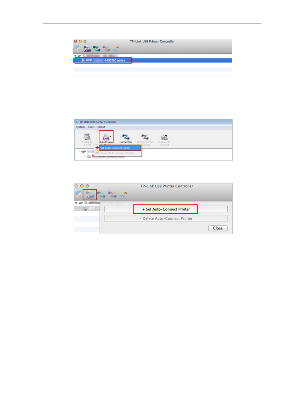
1 ) Double-click the icon
on your desktop to launch the USB Printer Controller.
2 ) Highlight the printer you share.
Windows
45
Page 50
Chapter 8
USB Settings
Mac
3 ) Click the Auto-Connect for printing tab to pull down a list, then select Set Auto-
Connect Printer.
Windows
Mac
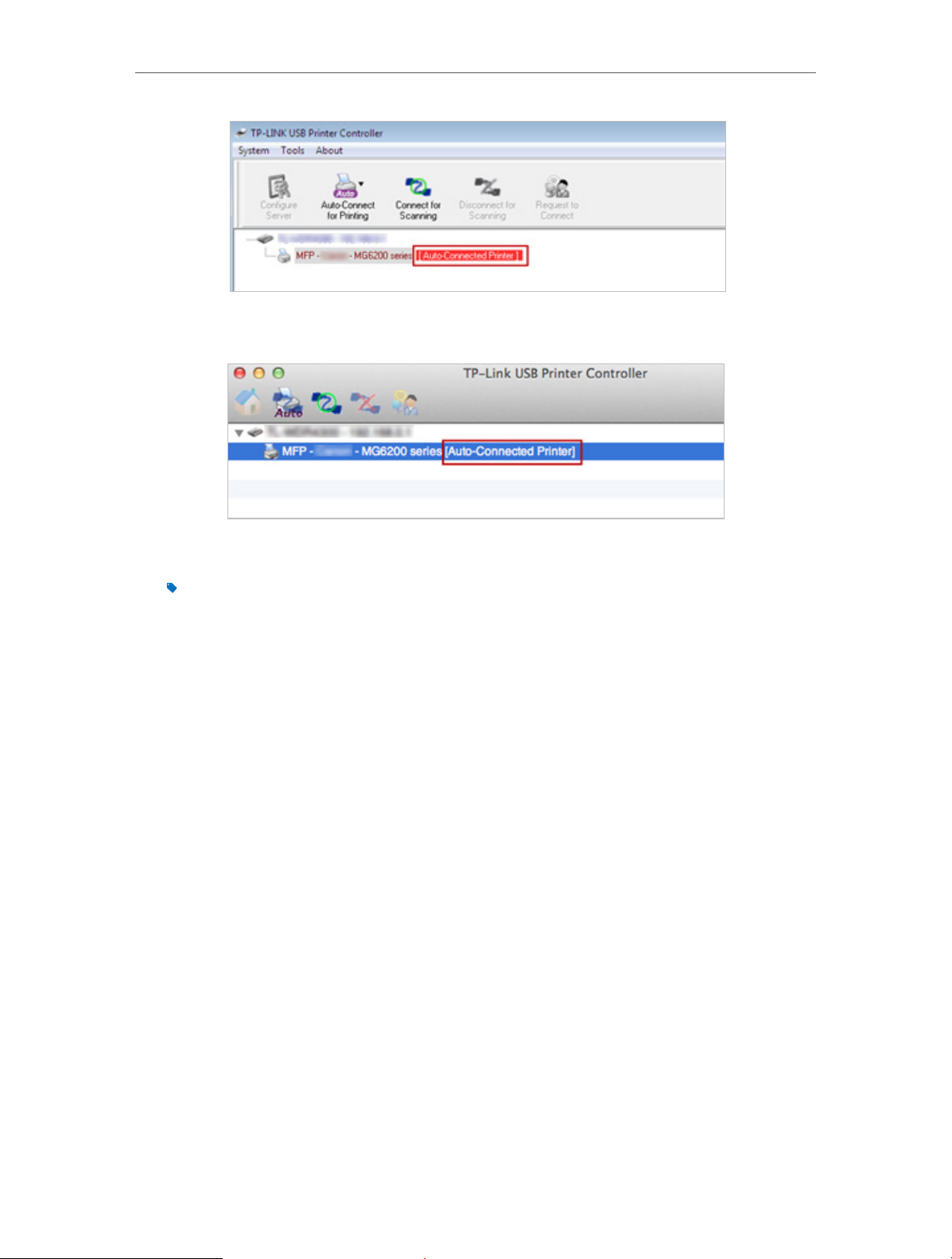
4 ) Select the printer you share, then click Apply.
46
Page 51

Chapter 8
USB Settings
Windows
Mac
5 ) You will see the printer marked as Auto-Connect Printer. Now you can print
with this printer.
47
Page 52
Chapter 8
USB Settings
Windows
Mac
Tips:
The Print Server also allows different clients to share the scan feature of MFPs (Multi-Function Printers). To
scan with TP-LINK USB Printer Controller, right-click the printer and select Network Scanner. Then, a scanning
window will pop up. Finish the scanning process by following on-screen instructions.
48
Page 53

Chapter 9
Parental Controls
This function allows you to block inappropriate, explicit and malicious websites, and
control access to specified websites at specified time.
Page 54
Chapter 9
Parental Controls
I want to:
How can I
do that?
control what types of websites my children or other home
network users can visit and even the time of day they are
allowed to access the Internet.
For example, I want to allow my children’s devices (e.g. a
computer or a tablet) to access only www.tp-link.com and
Wikipedia.org from 18:00 (6PM) to 22:00 (10PM) on weekdays
and not other time.
1. Visit http://tplinkmodem.net, and log in with the password
you set for the router.
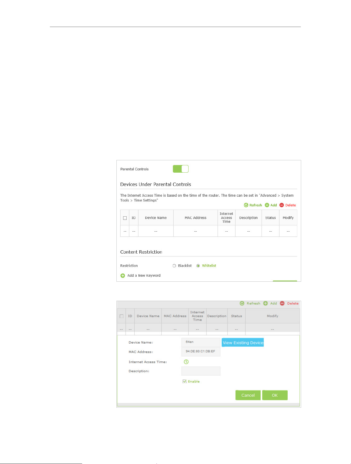
2. Go to Basic or Advanced > Parental Controls and enable
Parental Control.
3. Click Add.
50
Page 55
Chapter 9
Parental Controls
4. Click View Existing Devices, and select the device to be
controlled. Or, enter the Device Name and MAC Address
manually.
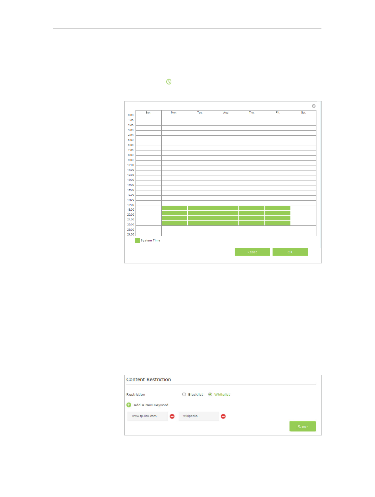
5. Click the
icon to set the Internet Access Time. Drag the
cursor over the appropriate cell(s) and click OK.
6. Enter a Description for the entry.
7. Select the checkbox to enable this entry and click OK.
8. Select the restriction mode.
1 ) In Blacklist mode, the controlled devices cannot access
any websites containing the specified keywords during
the Internet Access Time period.
2 ) In Whitelist mode, the controlled devices can only access
websites containing the specified keywords during the
Internet Access Time period.
51
Page 56

Chapter 9
Parental Controls
9. Click Add a New Keyword. You can add up to 200 keywords
for both Blacklist and Whitelist. Below are some sample
entries to allow access.
1 ) Enter a web address (e.g. www.tp-link.com) or a web
address keyword (e.g. wikipedia) to only allow or block
access to the websites containing that keyword.
2 ) Specify the domain suffix (eg. .edu or .org) to allow access
only to the websites with that suffix.
3 ) If you wish to block all Internet browsing access, do not
add any keyword to the Whitelist.
10. Enter the keywords or websites you want to add and click
Save.
Done!
Now you can control your children’s Internet access according
to your needs.
52
Page 57

Chapter 10
Guest Network
This function allows you to provide Wi-Fi access for guests without disclosing your
main network. When you have guests in your house, apartment, or workplace, you can
create a guest network for them. In addition, you can assign network authorities and
bandwidth for guests to ensure network security, privacy, and fluency.
• Create a Network for Guests
• Customize Guest Network Options
Page 58

Chapter 10
Guest Network
10. 1. Create a Network for Guests
1. Visit http://tplinkmodem.net, and log in with the password you set for the modem
router.
2. Go to Advanced > Guest Network. Locate the Wireless Settings section.
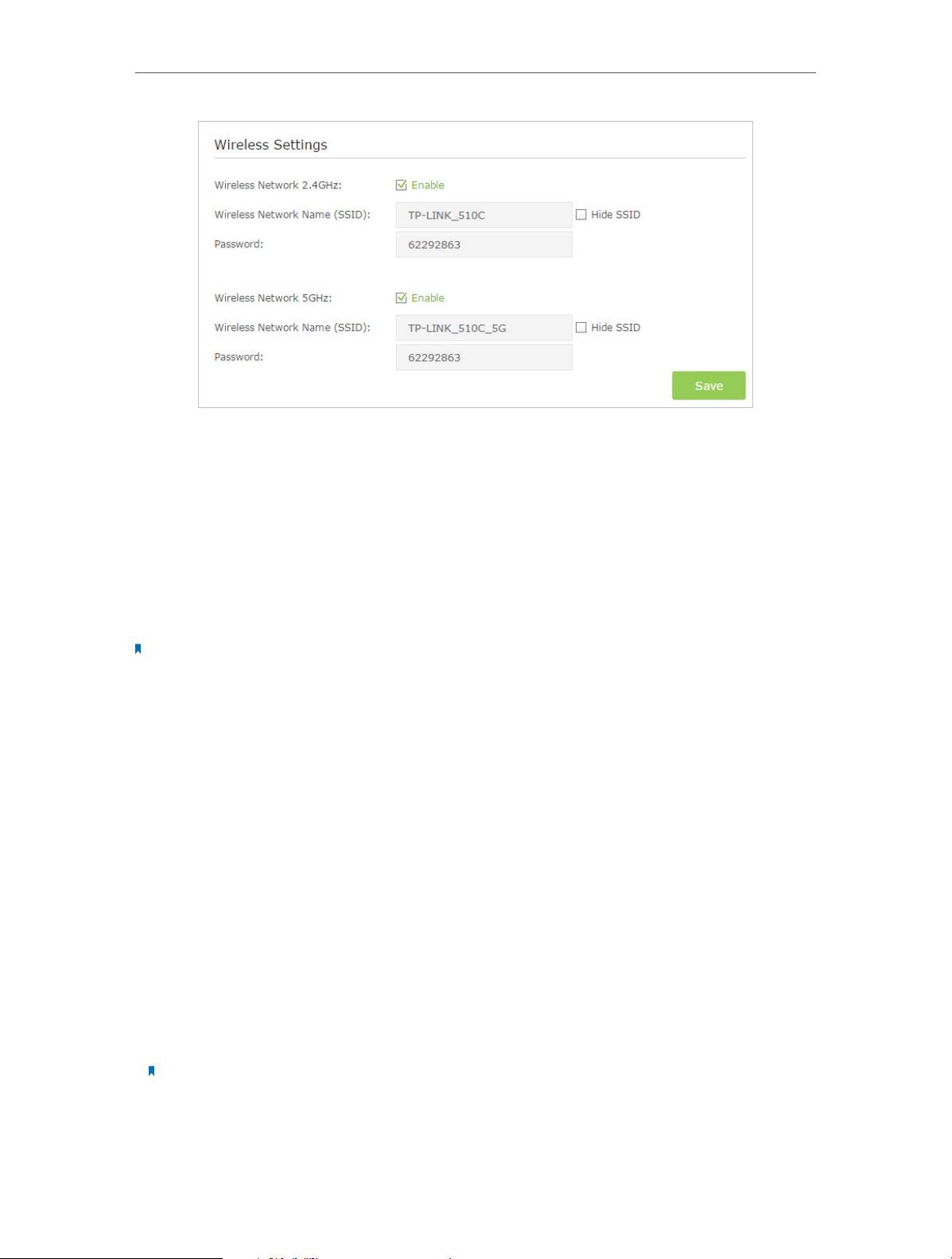
3. Create a 2.4GHz or 5GHz guest network according to your needs.
1 ) Enable Wireless Network 2.4GHz or Wireless Network 5GHz.
2 ) Set an easy-to-identify SSID. Don‘t select Hide SSID unless you want your guests
and other people to manually input this SSID for Wi-Fi access.
3 ) Set Security to WPA/WPA2 Personal, keep the default Version and Encryption
values, and set an easy-to-remember password.
4. Click Save. Now your guests can access your guest network using the SSID and
password you set!
Tips:
To view guest network information, go to Advanced > Status and find the Guest Network section.
10. 2. Customize Guest Network Options
1. Visit http://tplinkmodem.net, and log in with the password you set for the modem
router.
2. Go to Advanced > Guest Network.
54
Page 59

Chapter 10
Guest Network
3. Assign network authorities and bandwidth according to your needs.
• Allow guests to see each other
Select this checkbox to allow the clients in your guest network to access each other.
• Allow guests to access my local network
Select this checkbox to allow the clients in your guest network to access your local
network, not just Internet access.
• Allow guests to access my USB storage sharing
Select this checkbox to allow the clients in your guest network to access your
router’s USB storage sharing.
• Enable guest network bandwidth control
Select this checkbox to assign the upstream and downstream bandwidth of the
guest network. This option is available only when Bandwidth Control is enabled on
the Advanced > Bandwidth Control page.
4. Click Save. Now users in your guest network can enjoy only the network authorities
and bandwidth you assigned!
Tips:
To view guest network information, go to Advanced > Status and find the Guest Network section.
55
Page 60

Chapter 11
NAT Forwarding
Modem router’s NAT (Network Address Translation) feature makes the devices in the
LAN use the same public IP address to communicate in the Internet, which protects the
local network by hiding IP addresses of the devices. However, it also brings about the
problem that external host cannot initiatively communicate with the specified device
in the local network.
With forwarding feature the modem router can penetrate the isolation of NAT and
allows the external hosts in the Internet to initiatively communicate with the devices in
the local network, thus to realize some special functions.
TP-LINK modem router includes four forwarding rules. If two or more rules are set, the
priority of implementation from high to low is Virtual Servers, Port Triggering, UPNP
and DMZ.
This chapter contains the following sections:
• Share Local Resources in the Internet by Virtual Server
• Open Ports Dynamically by Port Triggering
• Make Applications Free from Port Restriction by DMZ
• Make Xbox Online Games Run Smoothly by UPnP
Page 61

Chapter 11
NAT Forwarding
11. 1. Share Local Resources in the Internet by Virtual
Server
When you build up a server in the local network and want to share it on the Internet,
Virtual Server can realize the service and provide it to the Internet users. At the same
time virtual server can keep the local network safe as other services are still invisible
from the Internet.
Virtual server can be used for setting up public services in your local network, such as
HTTP, FTP, DNS, POP3/SMTP and Telnet. Different service uses different service port.
Port 80 is used in HTTP service, port 21 in FTP service, port 25 in SMTP service and port
110 in POP3 service. Please verify the service port number before the configuration.
I want to:
How can I
do that?
share my personal website I’ve built in local network with my
friends through the Internet.
For example, the personal website has been built in my home PC
(192.168.1.100). I hope that my friends in the Internet can visit
my website in some way. The PC is connected to the modem
router with the WAN IP address 218.18.232.154.
Personal Website
Home
Modem Router
LAN
WAN: 218.18.232.154
1. Assign a static IP address to your PC, for example
192.168.1.100.
2. Visit http://tplinkmodem.net, and log in with the password
you set for the modem router.
3. Go to Advanced > NAT Forwarding > Virtual Servers, click
Add.
57
Page 62

Chapter 11
NAT Forwarding
4. Click View Existing Applications, and choose HTTP. The
external port, internal port and protocol will be automatically
filled with contents. Enter the PC’s IP address 192.168.1.100
in the Internal IP field.
5. Click OK to save the settings.
Tips:
1. It is recommended to keep the default settings of Internal Port and Protocol if you
are not clear about which port and protocol to use.
2. If the service you want to use is not in the Service Type, you can enter the
corresponding parameters manually. You should verify the port number that the
service needs.
3. You can add multiple virtual server rules if you want to provide several services in a
modem router. Please note that the External Port cannot be overlapped.
Done!
Users in the Internet can enter http:// WAN IP (in this example:
http://
1. WAN IP should be a public IP address. For the WAN IP is assigned dynamically by
2. If you have changed the default External Port, you should use http://
218.18.232.154) to visit your personal website.
Tips:
ISP, it is recommended to apply and register a domain name for the WAN by DDNS,
go to Set Up a Dynamic DNS Service Account for more information. Then you can
use http://
External Port or http://
domain name to visit the website.
WAN IP:
domain name: External Port to visit the website.
11. 2. Open Ports Dynamically by Port Triggering
Port triggering can specify a triggering port and its corresponding external ports. When
a host in the local network initiates a connection to the triggering port, all the external
ports will be opened for subsequent connections. The modem router can record the IP
address of the host. When the data from the Internet return to the external ports, the
58
Page 63

Chapter 11
NAT Forwarding
modem router can forward them to the corresponding host. Port triggering is mainly
applied to online games, VoIPs and video players. Common applications include MSN
Gaming Zone, Dialpad and Quick Time 4 players, etc.
Follow the steps below to configure the port triggering rules:
1. Visit http://tplinkmodem.net, and log in with the password you set for the modem
router.
2. Go to Advanced > NAT Forwarding > Port Triggering and click Add.
3. Click View Existing Applications, and select the desired application. The triggering
port and protocol, the external port and protocol will be automatically filled with
contents. Here we take application MSN Gaming Zone as an example.
4. Click OK to save the settings.
Tips:
1. You can add multiple port triggering rules according to your network need.
2. If the application you need is not listed in the Existing Applications list, please enter the parameters manually.
You should verify the external ports the application uses first and enter them into External Port field according
to the format the page displays.
11. 3. Make Applications Free from Port Restriction by
DMZ
When a PC is set to be a DMZ (Demilitarized Zone) host in the local network, it is totally
exposed to the Internet, which can realize the unlimited bidirectional communication
between internal hosts and external hosts. The DMZ host becomes a virtual server with
59
Page 64
Chapter 11
NAT Forwarding
all ports opened. When you are not clear about which ports to open in some special
applications, like IP camera and database software, you can set the PC to be a DMZ
host.
Note:
DMZ is more applicable in the situation that users are not clear about which ports to open. When it is enabled, the
DMZ host is totally exposed to the Internet, which may bring some potential safety hazard. If DMZ is not in use,
please disable it in time.
I want to:
How can I
do that?
make the home PC join the Internet online game without port
restriction.
For example, due to some port restriction, when playing the
online games, you can log in but cannot join a team with other
players. To solve this problem, set your PC as a DMZ with all
ports opened.
1. Assign a static IP address to your PC, for example
192.168.1.100.
2. Visit http://tplinkmodem.net, and log in with the password
you set for the modem router.
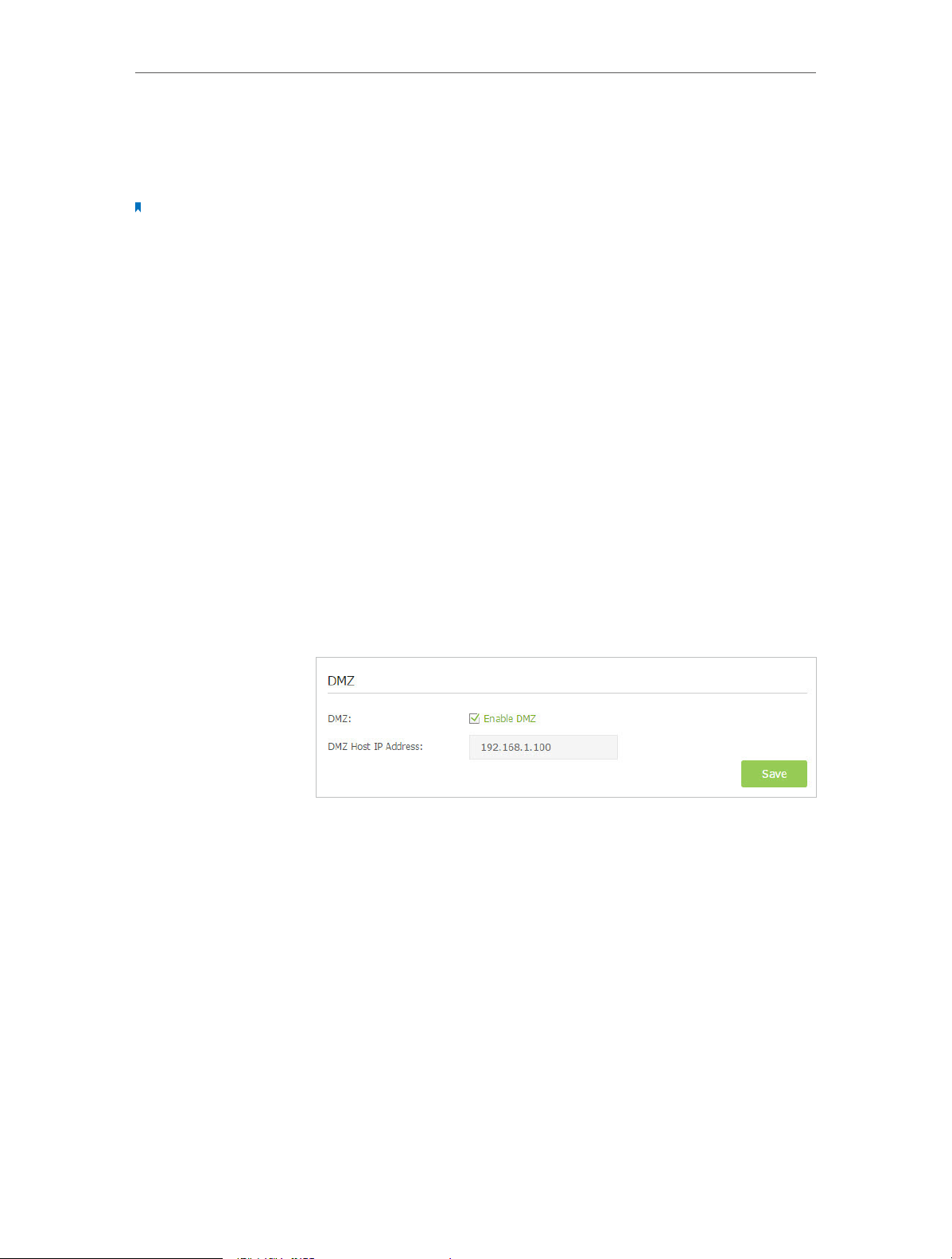
3. Go to Advanced > NAT Forwarding > DMZ and select the
checkbox to enable DMZ.
4. Enter the IP address 192.168.1.100 in the DMZ Host IP
Address filed.
5. Click Save to save the settings.
Done!
The configuration is completed. You’ve set your PC to a DMZ
host and now you can make a team to game with other players.
11. 4. Make Xbox Online Games Run Smoothly by UPnP
UPnP (Universal Plug and Play) protocol allows the applications or host devices
to automatically find the front-end NAT device and send request to it to open the
corresponding ports. With UPnP enabled, the applications or host devices in the
both sides of NAT device can freely communicate with each other realizing the
seamless connection of the network. You may need to enable the UPnP if you want
60
Page 65
Chapter 11
Modem RouterXbox
NAT Forwarding
to use applications for multiplayer gaming, peer-to-peer connections, real-time
communication (such as VoIP or telephone conference) or remote assistance, etc.
Tips:
1. UPnP is enabled by default in this modem router.
2. Only the application supporting UPnP protocol can use this feature.
3. UPnP feature needs the support of operating system (e.g. Windows Vista/ Windows 7/ Windows 8, etc. Some of
operating system need to install the UPnP components).
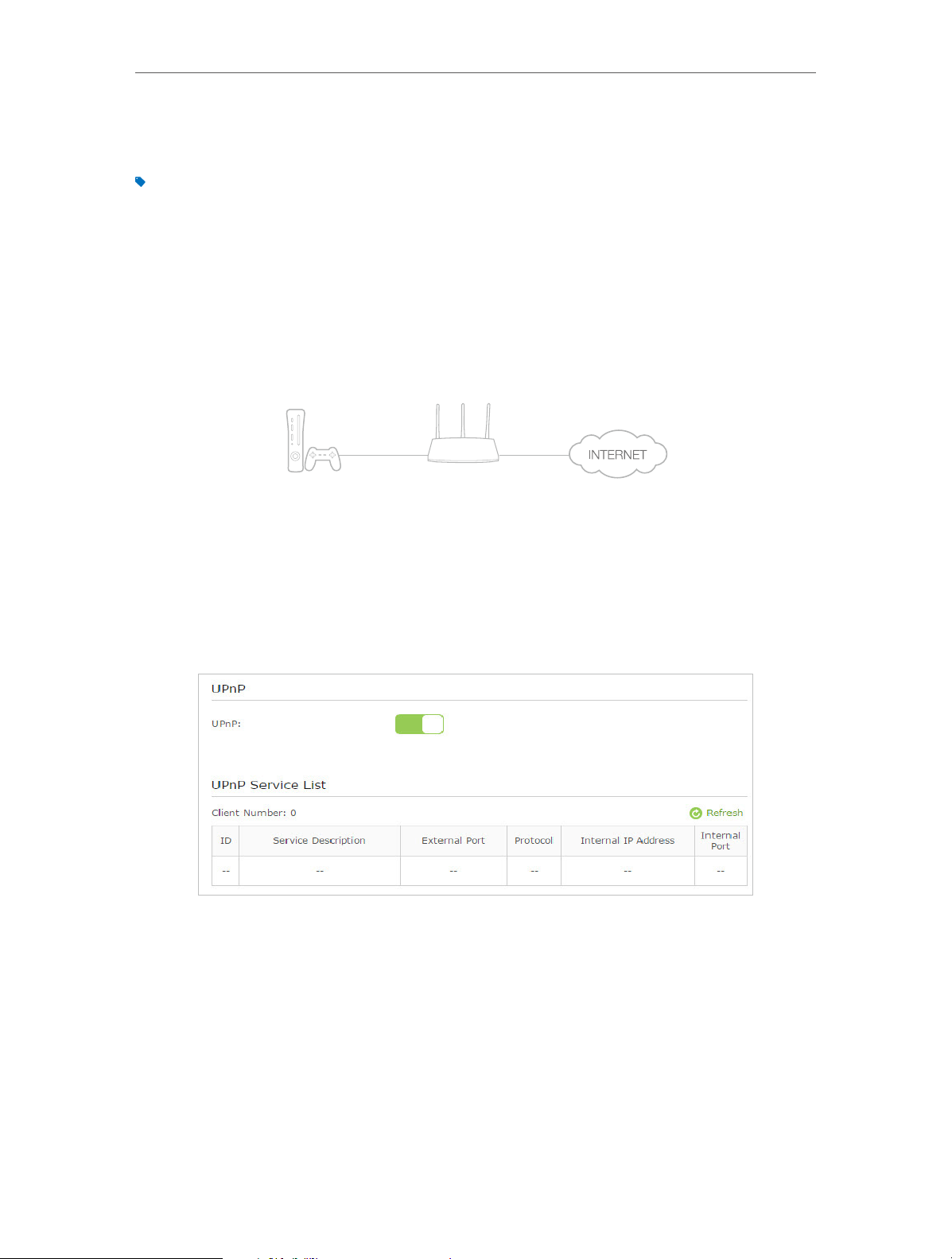
For example, When you connect your Xbox to the modem router which has connected
to the Internet to play online games, UPnP will send request to the modem router to
open the corresponding ports allowing the following data penetrating the NAT to
transmit. Therefore, you can play Xbox online games without a hitch.
LAN
WAN
If necessary, you can follow the steps to change the status of UPnP.
1. Visit http://tplinkmodem.net, and log in with the password you set for the modem
router;
2. Go to Advanced > NAT Forwarding > UPnP and toggle on or off according to your
needs.
61
Page 66

Chapter 12
Specify Your Network Settings
This chapter introduces how to change the default settings or adjust the basic
configuration of the modem router using the web-based management page.
This chapter contains the following sections:
• LAN Settings
• Wireless Settings
• Set Up a Dynamic DNS Service Account
• Interface Grouping
• Create Static Routes
• Set up a VPN Connection
• Set Up the IPv6 Tunnel
Page 67
Chapter 12
Specify Your Network Settings
12. 1. LAN Settings
12. 1. 1. Change the LAN IP Address
The modem router is preset with a default LAN IP 192.168.1.1, which you can use to log
in to its web-based management page. The LAN IP address together with the Subnet
Mask also defines the subnet that the connected devices are on. If the IP address
conflicts with another device on your local network or your network requires a specific
IP subnet, you can change it.
Follow the steps below to change your IP address.
1. Visit http://tplinkmodem.net, and log in with the password you set for the modem
router.
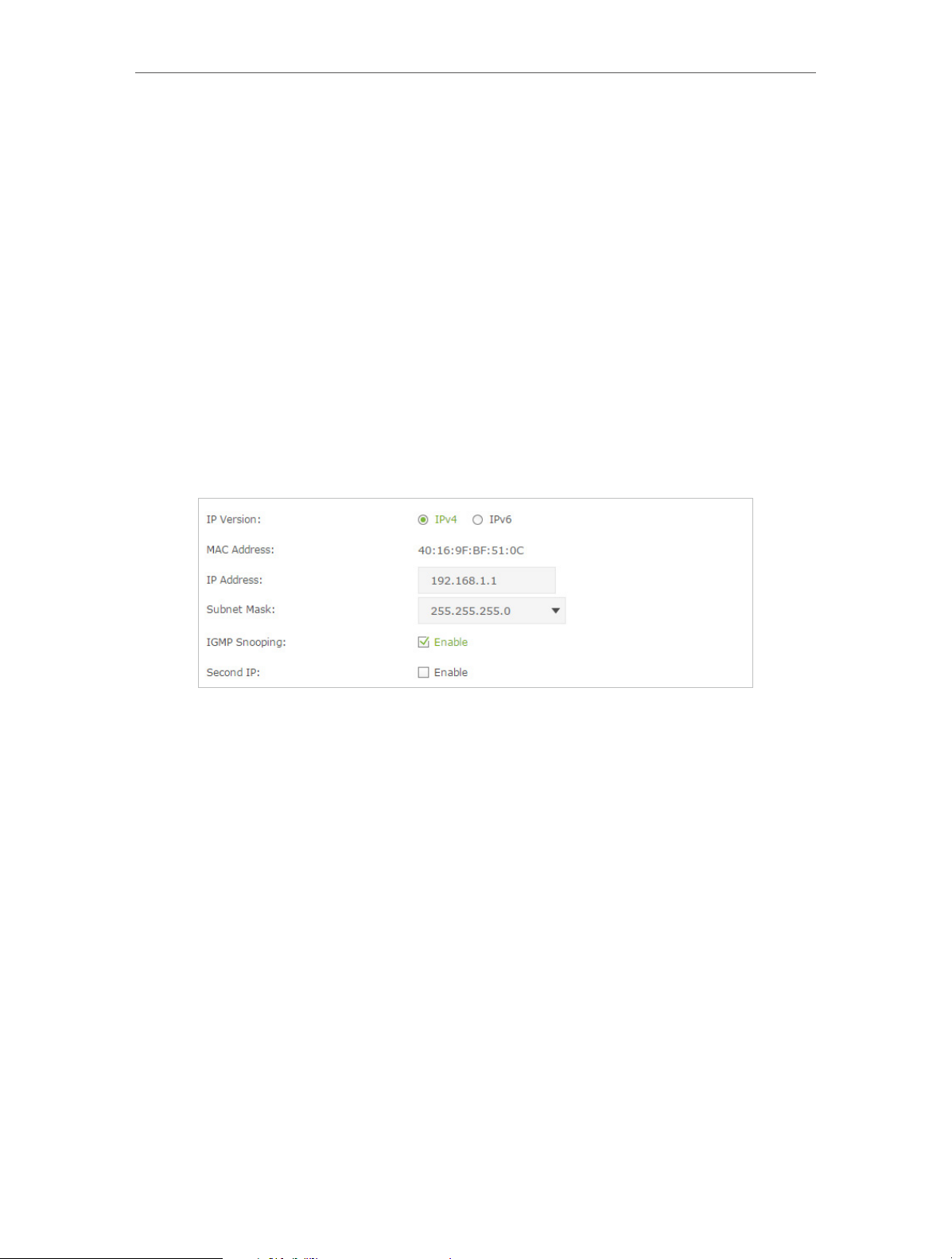
2. Go to Advanced > Network > LAN Settings page and select IPv4.
3. Type in a new IP Address appropriate to your needs.
4. Select the Subnet Mask from the drop-down list. The subnet mask together with
the IP address identifies the local IP subnet.
5. Keep IGMP Snooping as enabled by default. IGMP snooping is the process of
listening to IGMP (Internet Group Management Protocol) network traffic. The
function prevents hosts on a local network from receiving traffic for a multicast
group they have not explicitly joined.
6. You can configure the modem router’s Second IP and Subnet Mask for LAN interface
through which you can also access the web management page.
7. Leave the rest of the default settings as they are.
8. Click Save to make the settings effective.
12. 1. 2. Use the Modem Router as a DHCP Server
You can configure the modem router to act as a DHCP server to assign IP addresses to
its clients. To use the DHCP server function of the modem router, you must configure all
computers on the LAN to obtain an IP Address automatically.
63
Page 68
Chapter 12
Specify Your Network Settings
Follow the steps below to configure DHCP server.
1. Visit http://tplinkmodem.net, and log in with the password you set for the modem
router.
2. Go to Advanced > Network > LAN Settings page and select IPv4.
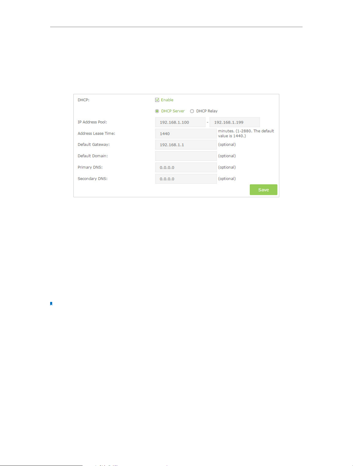
3. Select DHCP to enable the DHCP function and select DHCP Server.
4. Specify the IP Address Pool, the start address and end address must be on the same
subnet with LAN IP. The modem router will assign addresses within this specified
range to its clients. It is from 192.168.1.100 to 192.168.1.199 by default.
5. Enter a value for the Address Lease Time. The Address Lease Time is the amount of
time in which a DHCP client can lease its current dynamic IP address assigned by the
modem router. After the dynamic IP address expires, the user will be automatically
assigned a new dynamic IP address. The default is 1440 minutes.
6. Keep the rest of the settings as default and click Save to make your settings effective.
Note:
1. The modem router can be configured to work as a DHCP Relay. A DHCP relay is a computer that forwards DHCP
data between computers that request IP addresses and the DHCP server that assigns the addresses. Each of the
device’s interfaces can be configured as a DHCP relay. If it is enabled, the DHCP requests from local PCs will be
forwarded to the DHCP server that runs on WAN side.
2. You can also appoint IP addresses within a specified range to devices of the same type by using Condition Pool
feature. For example, you can assign IP addresses within the range (192.168.1.50 to192.168.1.80) to Camera
devices, thus facilitating the network management. Enable DHCP feature and configure the parameters according
to your actual situation on Advanced > Network > LAN Settings page.
12. 1. 3. Reserve LAN IP Addresses
You can view and add a reserved address for a client. When you specify an IP address
for a device on the LAN, that device will always receive the same IP address each time
when it accesses the DHCP server. If there are some devices in the LAN that require
64
Page 69
Chapter 12
Specify Your Network Settings
permanent IP addresses, please configure Address Reservation on the router for the
purpose.
Follow the steps below to reserve an IP address for your device.
1. Visit http://tplinkmodem.net, and log in with the password you set for the modem
router.
2. Go to Advanced > Network > LAN Settings page and select IPv4.
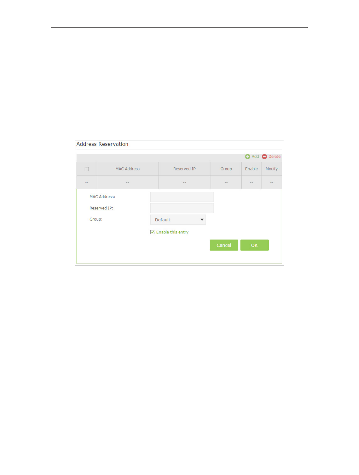
3. Scroll down to locate the Address Reservation table and click Add to add an address
reservation entry for your device.
4. Enter the MAC address of the device for which you want to reserve IP address.
5. Specify the IP address which will be reserved by the router.
6. Check to Enable this entry and click OK to make the settings effective.
12. 2. Wireless Settings
12. 2. 1. Specify Basic Wireless Settings
The modem router’s wireless network name (SSID) and password, and security option
are preset in the factory. The preset SSID and password can be found on the product
label. You can customize the wireless settings according to your needs.
Visit http://tplinkmodem.net, and log in with the password you set for the modem
router. Go to Basic > Wireless page.
65
Page 70
Chapter 12
Specify Your Network Settings
¾ To enable or disable the wireless function:
Enable the Wireless Network 2.4GHz or 5GHz. If you don’t want to use the wireless
function, just uncheck the box. If you disable the wireless function, all the wireless
settings won’t be effective.
¾ To change the wireless network name (SSID) and wireless password:
Enter a new SSID using up to 32 characters. The default SSID is TP-LINK_XXXX and the
value is case-sensitive.
Note:
If you use a wireless device to change the wireless settings, you will be disconnected when the settings are effective.
Please write down the new SSID and password for future use.
¾ To hide SSID:
Select Hide SSID, and your SSID will not broadcast. Your SSID won’t display when you
scan for local wireless network list on your wireless device and you need to manually
join the network.
¾ To change the mode or channel:
Go to Advanced > Wireless >Wireless Settings page and select the wireless network
2.4GHz or 5GHz.
Mode: Select the desired mode.
• 802.11n only: Select only if all of your wireless clients are 802.11n devices.
• 802.11gn mixed: Select if you are using both 802.11g and 802.11n wireless clients.
• 802.11bgn mixed: Select if you are using a mix of 802.11b, 11g, and 11n wireless
clients.
Note: When 802.11n only mode is selected, only 802.11n wireless stations can connect to the modem router.
It is strongly recommended that you select 802.11bgn mixed, and all of 802.11b, 802.11g, and 802.11n wireless
stations can connect to the modem router.
66
Page 71
Chapter 12
Specify Your Network Settings
• 802.11ac/n mixed (5Ghz): Select if you are using both 802.11ac and 802.11n wireless
clients.
• 802.11a/n/ac mixed (5Ghz): Select if you are using a mix of 802.11a, 802.11n and
802.11ac wireless clients. It is strongly recommended that you select 11a/n/ac mixed.
Channel: Select the channel you want to use from the drop-down list. This field
determines which operating frequency will be used. It is not necessary to change the
wireless channel unless you notice interference problems with another nearby access
point.
Channel Width: Select the channel width from the drop-down list. The default setting is
Automatic, which can adjust the channel width for your clients automatically.
¾ To change the security option:
1. Go to Advanced > Wireless >Wireless Settings page.
2. Select the wireless network 2.4GHz or 5GHz.
3. Select an option from the Security drop-down list. The router provides four options,
None, WPA/WPA2 Personal (Recommended), WPA/WPA2 Enterprise, WEP. WPA2
uses the newest standard and the security level is the highest. We recommend you
don’t change the default settings unless necessary.
12. 2. 2. Use WPS for Wireless Connection
You can use WPS feature to add a new wireless device to your existing network quickly.
Method 1 Use the Wi-Fi Protected Setup Button
Use this method if your client device has a Wi-Fi Protected Setup button.
1. Press the WPS/RESET button on the back panel of the modem router for 1 second.
2. Press the WPS button of the client device directly.
3. The WPS LED flashes for about 3 minutes during the WPS process.
4. When the WPS LED is on, the client device has successfully connected to the
modem router.
67
Page 72
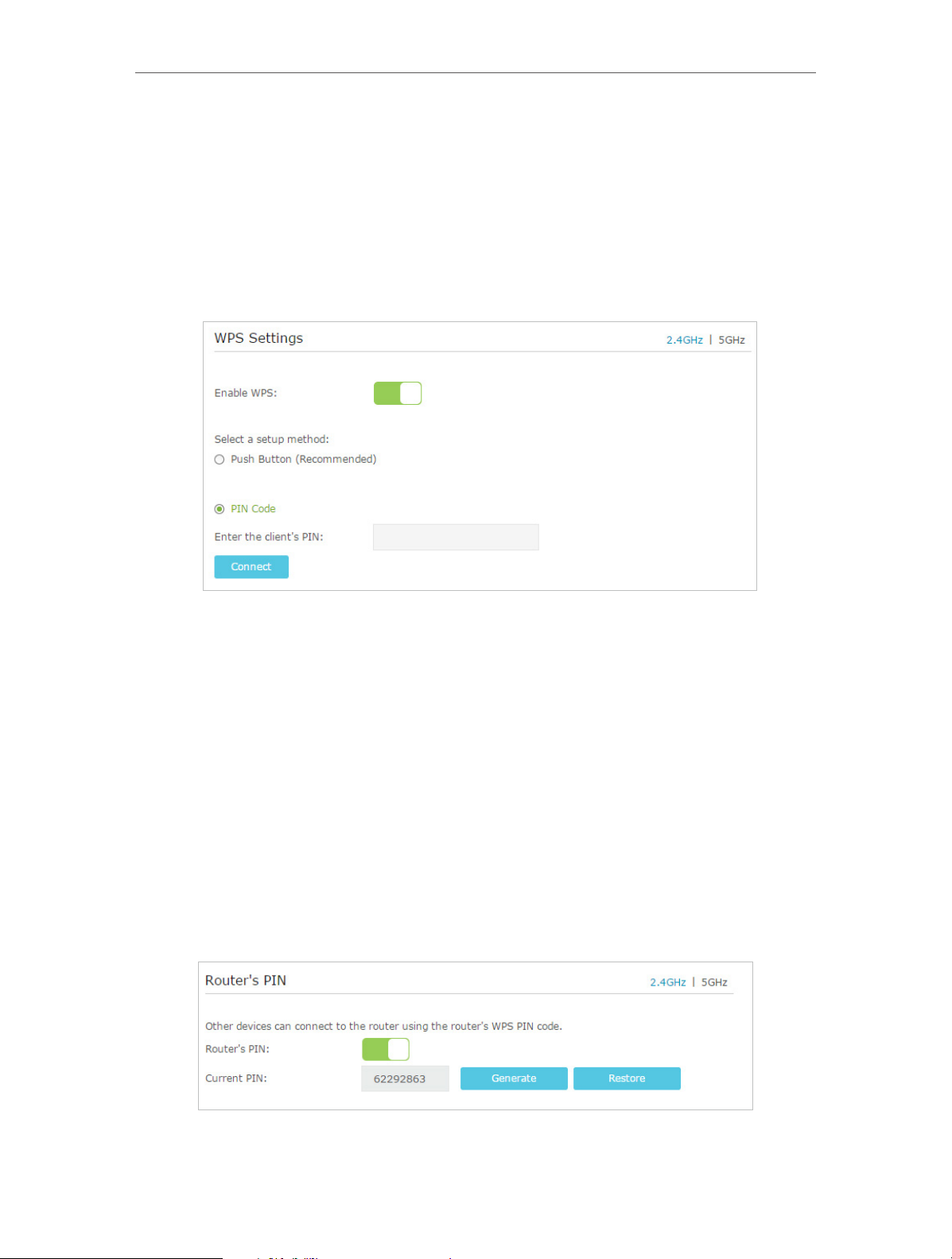
Chapter 12
Specify Your Network Settings
Method 2 Enter the client device’s PIN on the modem router
1. Visit http://tplinkmodem.net, and log in with the password you set for the modem
router.
2. Go to Advanced > Wireless >WPS page. Select the wireless network 2.4GHz or 5GHz
according to your wireless client.
3. Keep the default WPS status as Enabled and select the PIN Code radio button.
4. Enter the client device’s PIN in the field on the above WPS screen. Then click the
Connect button.
5. “Connect successfully” will appear on the above screen, which means the client
device has successfully connected to the modem router.
Method 3 Enter the modem router’s PIN on your client device
Use this method if your client device asks for the modem router’s PIN.
1. Visit http://tplinkmodem.net, and log in with the password you set for the modem
router.
2. Go to Advanced > Wireless >WPS page. Select the wireless network 2.4GHz or 5GHz
according to your wireless client.
68
Page 73

Chapter 12
Specify Your Network Settings
3. Keep the Router’s PIN status as enabled. Take a note of the Current PIN of the
modem router. You can also click the Generate button to get a new PIN.
4. On the client device, enter the modem router’s PIN. (The default PIN is also labeled
on the bottom of the modem router.)
5. The WPS LED flashes for about three minutes during the WPS process.
6. When the WPS LED is on, the client device has successfully connected to the
modem router.
Note:
1. The WPS LED on the modem router will light green for five minutes if the device has been successfully added to
the network.
2. The WPS function cannot be configured if the wireless function of the modem router is disabled. Please make
sure the wireless function is enabled before configuring the WPS.
12. 2. 3. Schedule Your Wireless Function
You can automatically turn off your wireless network (both 2.4GHz and 5GHz) at time
when you do not need the wireless connection.
1. Visit http://tplinkmodem.net, and log in with the password you set for the modem
router.
2. Go to Advanced > Wireless > Wireless Schedule page.
3. Select the 2.4GHz wireless network to configure. Toggle on the button to enable
the Wireless Schedule feature.
69
Page 74

Chapter 12
Specify Your Network Settings
4. Set the time. Drag the cursor to cover the time area and click Save to make the
settings effective. The selected time will be in green.
5. Repeat steps 3 and 4 to set time for 5GHz wireless network.
Note:
1. If you just set time for one wireless band, the other wireless band is still always on, so set time for both of the two
bands to schedule your whole wireless network.
2. The wireless LED (2.4GHz , 5GHz ) will turn off if the corresponding wireless network is disabled.
3. The wireless network will be automatically turned on after the time period you set.
12. 2. 4. View Wireless Information
¾ To view the detailed wireless network settings:
1. Visit http://tplinkmodem.net, and log in with the password you set for the modem
router.
2. Go to Advanced > Status page. You can see the Wireless box.
3. Select 2.4GHz or 5GHz to view the wireless details.
70
Page 75

Chapter 12
Tips: You can also see the wrieless details by clicking the router icon on Basic> Network Map.
Specify Your Network Settings
¾ To view the detailed information of the connected wireless clients:
1. Visit http://tplinkmodem.net, and log in with the password you set for the modem
router.
2. Go to Advanced > Wireless > Statistics page.
3. You can view the detailed information of the wireless clients, including its connected
wireless band and security option as well as the packets transmitted.
Tips: You can also see the wrieless details by clicking the wireless clients icon on Basic> Network Map.
12. 2. 5. Advanced Wireless Settings
Advanced wireless settings are for those who have a network concept. If you are not
familiar with the settings on this page, it’s strongly recommended that you keep the
provided default values; otherwise it may result in lower wireless network performance.
1. Visit http://tplinkmodem.net, and log in with the password you set for the modem
router.
2. Go to Advanced > Wireless > Advanced Settings page.
71
Page 76

Chapter 12
Specify Your Network Settings
• Beacon Interval: Enter a value between 25 and 1000 in milliseconds to determine the
duration between which beacon packets are broadcasted by the router to synchronize
the wireless network. The default is 100 milliseconds.
• RTS Threshold: Enter a value between 1 and 2346 to determine the packet size of
data transmission through the router. By default, the RTS (Request to Send) Threshold
size is 2346. If the packet size is greater than the preset threshold, the router sends
Request to Send frames to a particular receiving station and negotiates the sending
of a data frame, or else the packet will be sent immediately.
• DTIM Interval: Enter a value between 1 and 255 to determine the interval of the
Delivery Traffic Indication Message (DTIM). 1 indicates the DTIM Interval is the same
as Beacon Interval.
• Group Key Update Period: Enter the number of seconds to control the time interval
for the encryption key automatic renewal. The default is 0, indicating no key renewal.
• Enable WMM: This feature guarantees the packets with high-priority messages being
transmitted preferentially. WMM is enabled compulsively under 802.11n or 802.11ac
mode. It is strongly recommended to enable WMM.
• Enable Short GI: This feature is enabled by default and recommended to increase the
data capacity by reducing the Guard Interval (GI) time.
• AP Isolation: Select this checkbox to enable the AP Isolation feature that allows you to
confine and restrict all wireless devices on your network from interacting with each
other, but still able to access the Internet. AP isolation is disabled by default.
• WDS: Select this checkbox to enable the WDS (Wireless Distribution System) Bridging
feature to allow the router to bridge with another access point (AP) in a wireless local
area network (WLAN). Refer to Appendix B: Troubleshooting for detailed instructions.
72
Page 77

Chapter 12
Specify Your Network Settings
12. 3. Set Up a Dynamic DNS Service Account
Most ISPs (Internet service providers) assign a dynamic IP address to the router and
you can use this IP address to access your router remotely. However, the IP address can
change any time and you don’t know when it changes. In this case, you might need
the DDNS (Dynamic Domain Name Server) feature on the router to allow you and your
friends to access your router and local servers (FTP, HTTP, etc.) using domain name, in
no need of checking and remembering the IP address.
Note: DDNS does not work if the ISP assigns a private WAN IP address (such as 192.168.1.x) to the modem router.
To set up DDNS, please follow the instructions below:
1. Visit http://tplinkmodem.net, and log in with the password you set for the modem
router.
2. Go to Advanced > Network> Dynamic DNS.
3. Select the DDNS service provider (Dyndns or NO-IP). If you don’t have a DDNS
account, select a service provider and click Go to register.
4. Enter the username, password and domain name of the account (such as lisa.ddns.
net).
5. Click Login and Save.
Tips: If you want to use a new DDNS account, please Logout first, then login with the new account.
12. 4. Interface Grouping
I want to:
Divide my devices connected to the modem router into different
groups and disallow devices’ cross-group communication.
For example, in my house, devices connected to LAN1 and LAN3
are for work, while others for entertainment. I want to isolate
working devices from others while keep all devices’ access to
the Internet.
73
Page 78

Chapter 12
Specify Your Network Settings
How can I
do that?
1. Visit http://tplinkmodem.net, and log in with the password
you set for the modem router.
2. Go to Advanced > Network > Interface Grouping to open the
configuration page where some interfaces can be grouped
together.
3. Click to Add a new group.
4. Name the group.
5. Check the boxes of LAN1 and LAN3 in Available LAN. Here
Wi-Fi 2.4G network and Wi-Fi 5G network are viewed as a
LAN interface respectively.
6. Click Enable Group Isolation to isolate working devices and
disallow other devices from communicating with them.
7. Click OK to save the settings.
74
Page 79

Chapter 12
Specify Your Network Settings
Done!
Now your working devices connected to LAN1 and LAN3 are in
an isolated group!
Note: VLAN function is enabled by default. You cannot disable it when IPTV is
enabled.
12. 5. Create Static Routes
A static route is a pre-determined path that network information must travel to reach
a specific host or network. Data from one point to another will always follow the same
path regardless of other considerations. Normal Internet usage does not require this
setting to be configured.
I want to:
Visit multiple networks and multiple servers at the same time.
For example, in a small office, my PC can surf the Internet, but I
also want to visit my company’s server. Now I have a switch and
another router. I connect the devices as shown in the following
figure so that the physical connection between my PC and my
company’s server is achieved. To surf the Internet and visit my
company’s network at the same time, I need to configure the
static routing.
How can I
do that?
Modem router
LAN: 192.168.1.1
Switch
192.168.1.100
Router 2
WAN: 172.30.30.100
LAN: 192.168.1.2
My PC
Company’s server
172.30.30.1
1. Make sure the routers use different LAN IP addresses on the
same subnet. Disable Router 2’s DHCP function.
2. Visit http://192.168.1.1, and log in with the password you set
for the modem router.
3. Go to Advanced > Network > Advanced Routing. Select your
current WAN Interface and click Save.
75
Page 80
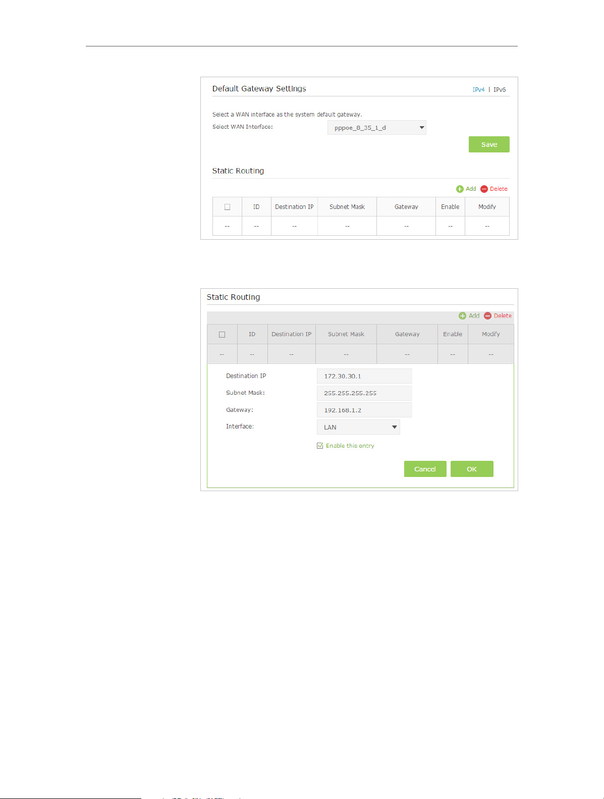
Chapter 12
Specify Your Network Settings
4. Click Add to add a new static routing entry. Finish the settings
according to the following explanations:
• Destination IP: The destination IP address that you want to
assign to a static route. This IP address cannot be on the same
subnet with the WAN IP or LAN IP of the router. In the example,
the IP address of the company network is the destination IP
address, so here enters 172.30.30.1.
• Subnet Mask: Determines the destination network with the
destination IP address. If the destination is a single IP address,
enter 255.255.255.255; otherwise, enter the subnet mask of
the corresponding network IP. In the example, the destination
network is a single IP, so here enters 255.255.255.255.
• Gateway: The IP address of the gateway device to which the
data packets will be sent. This IP address must be on the same
subnet with the router’s IP which sends out the data. In the
example, the data packets will be sent to the LAN port of
76
Page 81

Chapter 12
Router 2 and then to the Server, so the default gateway should
be 192.168.1.2.
• Interface: Determined by the port (WAN/LAN) that sends
out the data packets. In the example, the data is sent to the
gateway through the LAN port, so LAN should be selected.
5. Check to enable this entry and click OK to save the settings.
Specify Your Network Settings
Done!
Open a web browser on your PC. Enter the company server’s IP
address to visit the company network.
12. 6. Set up a VPN Connection
VPN (Virtual Private Network) is a private network established across the public network,
generally via the Internet. However, the private network is a logical network without
any physical network lines, so it is called Virtual Private Network.
With the wide application of the Internet, more and more data are needed to be shared
through the Internet. Connecting the local network to the Internet directly, though can
allow the data exchange, will cause the private data to be exposed to all the users on
the Internet.
The VPN (Virtual Private Network) technology is developed and used to establish
the private network through the public network, which can provides a secure
communication to a remote computer or remote network, and guarantee a secured
data exchange. IPSec is one of the major implementations of VPNs.
I want to:
Establish an IPSec VPN tunnel to connect two LANs via Internet so
that the hosts in different remote LANs are able to communicate
with each as if they are in the same LAN.
For example, I am the network administrator of a regional office,
I need to let my office staff can visit the headquarter’s servers
and resources, and vice versa. I know that the modem router
in my office and the device in headquarter both support IPSec
VPN feature, so I decide to set up a VPN connection with the
headquarter office.
The following diagram is a typical VPN topology. Here Site A
refers to regional office’s network (local network). And Site B
refers to the headquarter’s network (remote network) which I
want to connect.
77
Page 82

Chapter 12
Specify Your Network Settings
How can I
do that?
Site A
Modem router 1
PC 1
WAN: 219.134.112.246
LAN: 192.168.1.1
Subnetmask: 255.255.255.0
WAN: 219.134.112.247
LAN: 192.168.2.1
Subnetmask: 255.255.255.0
Modem Router 2
Site B
PC 2
1. Make sure of the topology you want to build and record site
A (local network) and site B (remote network)’s LAN IP and
WAN IP.
2. Configuration on site A (local network).
1 ) Visit http://tplinkmodem.net, and log in with the password
you set for the modem router.
2 ) Go to Advanced > Network > IPSec VPN to open the
configuration page. Click Add to set up a VPN tunnel.
78
Page 83
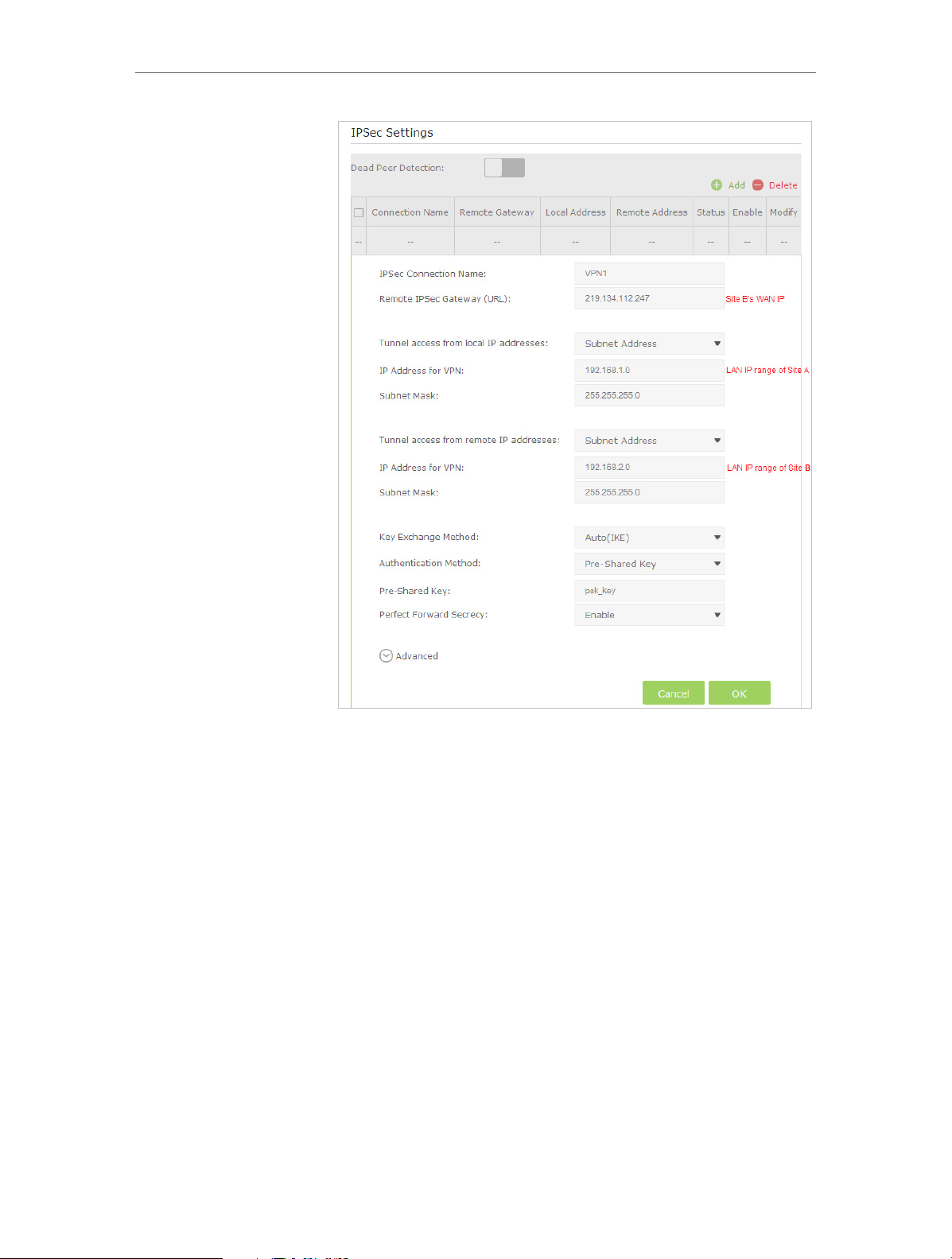
Chapter 12
Specify Your Network Settings
3 ) In the IPSec Connection Name column, specify a name.
4 ) In the Remote IPSec Gateway (URL) column, Enter Site B’s
WAN IP address.
5 ) To configure Site A’s LAN:
In the Tunnel access from local IP addresses column, here we
take Subnet Address as an example. Then input the LAN IP
range of Site A in the IP Address for VPN column, and input
Subnet Mask of Site A.
6 ) To configure Site B’s LAN:
In the Tunnel access from local IP addresses column, here we
take Subnet Address as an example. Then input the LAN IP
range of Site B in the IP Address for VPN column, and input
Subnet Mask of Site B.
7 ) Select the Key Exchange Method for the policy. We select
Auto(IKE) here.
79
Page 84

Chapter 12
Specify Your Network Settings
8 ) Enter the Pre-Shared Key for IKE authentication. Then
keep Perfect Forward Secrecy enabled.
Note:
The key should consist of visible characters without blank space.
Make sure Site A and Site B use the same key.
9 ) Leave the Advanced Settings as default value. Then click
OK to save.
3. Configuration on Site B (remote network). Refer to step 2
configuration on Site A and make sure that Site A and Site B
use the same pre-shared keys and Perfect Forward Secrecy
settings.
4. The Status column will change to UP if the VPN connection
has been set up successfully.
5. Check the VPN connection. You can ping site B’ LAN IP
from your computer in site A to verify that the IPSec VPN
connection is set up correctly.
Tips: To check the VPN connection, you can do the following.
On the host in Site A, press [Windows Logo] + [R] to open Run dialog. Input “cmd”
and hit OK.
In the CLI window, type in “ping 192.168.2.x” (“192.168.2.x”
can be IP address of any host in Site B). Then press [Enter].
80
Page 85
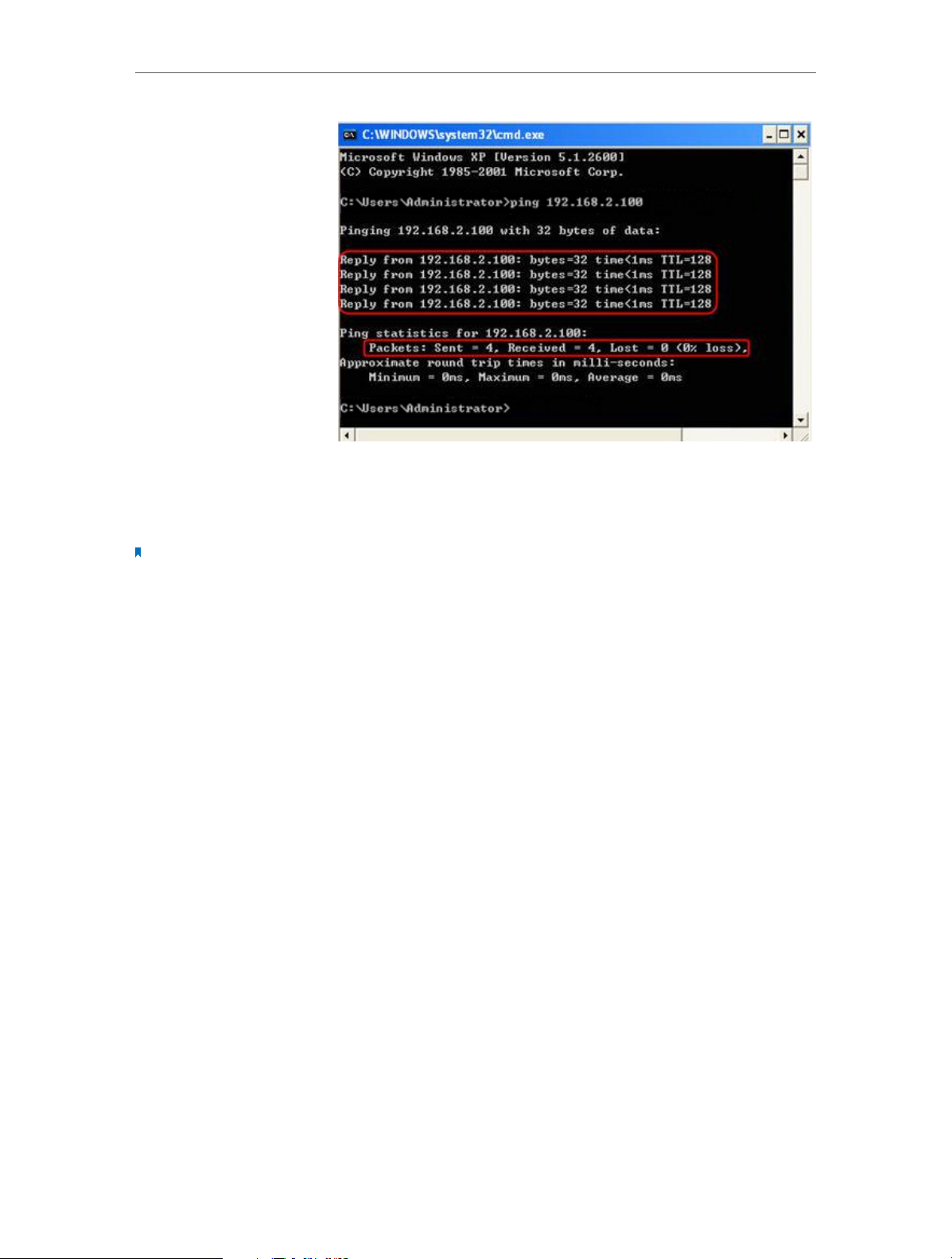
Chapter 12
Specify Your Network Settings
If Ping proceeds successfully (gets replies from host in Site B),
the IPSec connection is working properly now.
Done!
Note:
1. The product supports a maximum of ten simultaneous connections.
2. If one of the site has been off line for a while, for example, if Site A has been disconnected, on Site B you need to
click Disable and then click Enable after Site A back on line in order to re-establish the IPSec tunnel.
Now IPSec VPN is implemented to establish a connection.
12. 7. Set Up the IPv6 Tunnel
The IPv6 Tunnel feature helps you obtain IPv6 resources based on an IPv4 WAN
connection or vice versa.
IPv6 Tunnel is a transition mechanism that enables IPv6-only hosts to reach IPv4
services or vice versa and allows isolated IPv6 hosts and networks to reach each other
over IPv4-only infrastructure before IPv6 completely supplants IPv4. It is a temporary
solution for networks that do not support native dual-stack, where both IPv6 and IPv4
run independently.
The modem router provides three tunneling mechanisms: 6to4, 6rd and DS-Lite. The
way to set up 6rd and DS-Lite tunnel are similar.
12. 7. 1. Use the Public IPv6 Tunnel Service-6to4
The 6to4 tunnel is a kind of public service. If there is any 6to4 server in your network,
you can use this mechanism to access IPv6 service. If your ISP provides you with an
IPv4-only connection but you want to visit IPv6 websites, you can try to set up a 6to4
tunnel.
81
Page 86
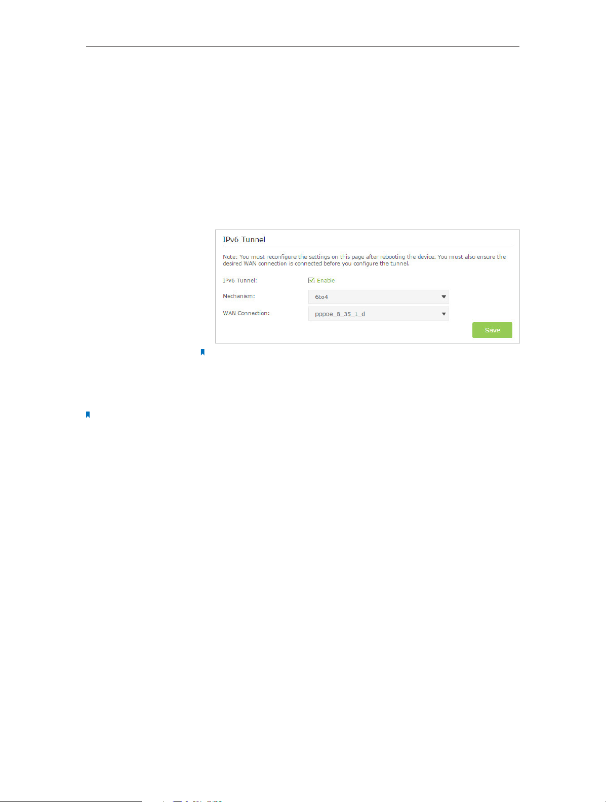
Chapter 12
Specify Your Network Settings
I want to:
How can I
do that?
Set up the IPv6 tunnel though my ISP doesn’t provide me with
the tunnel service.
1. Visit http://tplinkmodem.net, and log in with the password
you set for the modem router.
2. Go to Advanced > Network > IPv6 Tunnel.
3. Tick the check box, select 6to4 as the tunneling mechanism
and select a WAN connection from the drop-down list, then
click Save.
Note:
If there is no available WAN connection to choose, make sure you have connected to
the Internet and the connection type is not Bridge.
Done!
Note:
Still not being able to access IPv6 resources means that not any 6to4 public server was found in your network. You
can contact your ISP to sign up for IPv6 connection service.
Now you can visit the IPv6 websites with the 6to4 tunnel.
12. 7. 2. Specify the 6rd Tunnel with Parameters Provided by Your ISP
I want to:
How can I
How can I
do that?
do that?
Specify the 6rd tunnel with the parameters provided by my 6rd
tunnel service provider.
1. Visit http://tplinkmodem.net, and log in with the password
you set for the modem router.
2. Go to Advanced > Network > IPv6 Tunnel.
3. Tick the check box, select 6rd as the tunneling mechanism
and select a WAN connection from the drop-down list.
4. According to the parameters provided by your ISP, choose
Auto or Manual. More parameters are needed if you choose
Manual.
5. Click Save.
82
Page 87
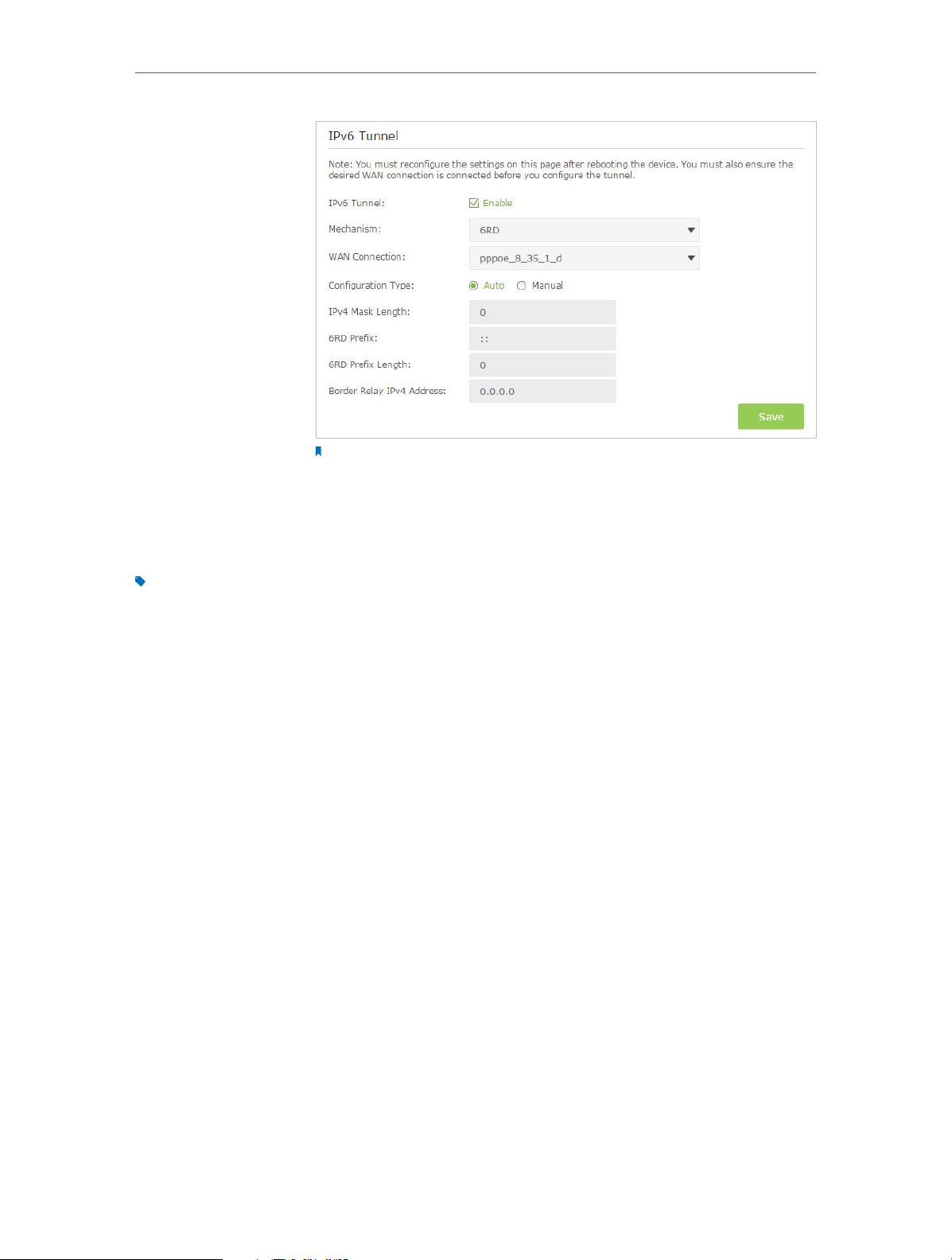
Chapter 12
Note:
If there is no available WAN connection to choose, make sure you have connected to
the Internet and the connection type is not Bridge.
Specify Your Network Settings
Done!
Tips:
The way to set up DS-Lite tunnel is similar to that of 6rd tunnel. If you are provided with an IPv6-only WAN connection
and have signed up for DS-Lite tunnel service, specify the DS-Lite tunnel by referring to the steps above.
Now you can visit the IPv6 websites with the 6rd tunnel.
83
Page 88

Chapter 13
Administrate Your Network
This chapter introduces how to change the system settings and administrate your
modem router’s network.
This chapter contains the following sections:
• Set System Time and Region
• Update the Firmware
• Back up and Restore Configuration Settings
• Change the Administrator Account
• Local Management
• Remote Management
• System Log
• Monitor the Internet Traffic Statistics
• CWMP Settings
• SNMP Settings
Page 89
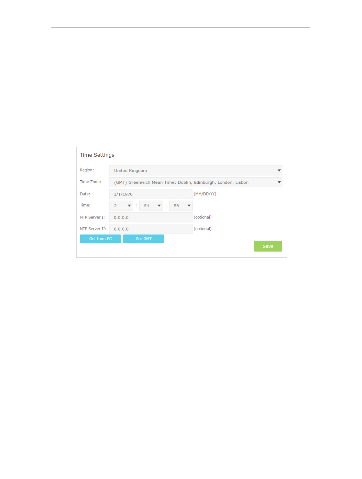
Chapter 13
Administrate Your Network
13. 1. Set System Time and Region
System time is the time displayed while the modem router is running. The system time
you configure here will be used for other time-based functions like Parental Controls
and Wireless Schedule. You can manually set how to get the system time.
Follow the steps below to set your system time.
1. Visit http://tplinkmodem.net, and log in with the password you set for the modem
router.
2. Go to Advanced > System Tools > Time Settings page.
3. Select your Region from the drop-down list. The region is where the wireless
function of the device can be used. It may be illegal to use the wireless function
of the device in a region other than regions specified in the list. If your country or
region is not listed, please contact your local government agency for assistance.
4. Configure the system time using the following methods :
Manually: Select your time zone and enter your local time.
Get from PC: Click this button if you want to use the current managing PC’s time.
Get GMT: Click this button if you want to get time from the Internet. Make sure your
modem router can access the Internet before you select this way to get system
time.
5. Click Save to make your settings effective.
6. After setting the system time, you can set Daylight Saving time according to your
needs. Tick the checkbox to enable Daylight Saving, set the start and end time and
then click Save to make the settings effective.
85
Page 90

Chapter 13
Administrate Your Network
13. 2. Update the Firmware
TP-LINK is dedicated to improving and enriching the product features, giving you a
better network experience. We will release the latest firmware at TP-LINK official
website, you can download the latest firmware file from our website: www.tp-link.com
and upgrade the firmware to the latest version.
Follow the steps below to update your firmware to the latest.
1. Download the latest firmware file from our website: www.tp-link.com.
2. Visit http://tplinkmodem.net, and log in with the password you set for the modem
router.
3. Go to Advanced > System Tools > Firmware Upgrade page.
4. Click Browse to locate the downloaded new firmware file, and click Upgrade.
5. Wait for the upgrading and then the modem router will automatically reboot.
Note:
1. Before upgrading the firmware, it’s better to back up your current settings. For more details, refer toBack up and
Restore Configuration Settings.
2. During the upgrading process, do not turn off or reset the router.
3. The upgraded firmware version must correspond to the hardware.
86
Page 91
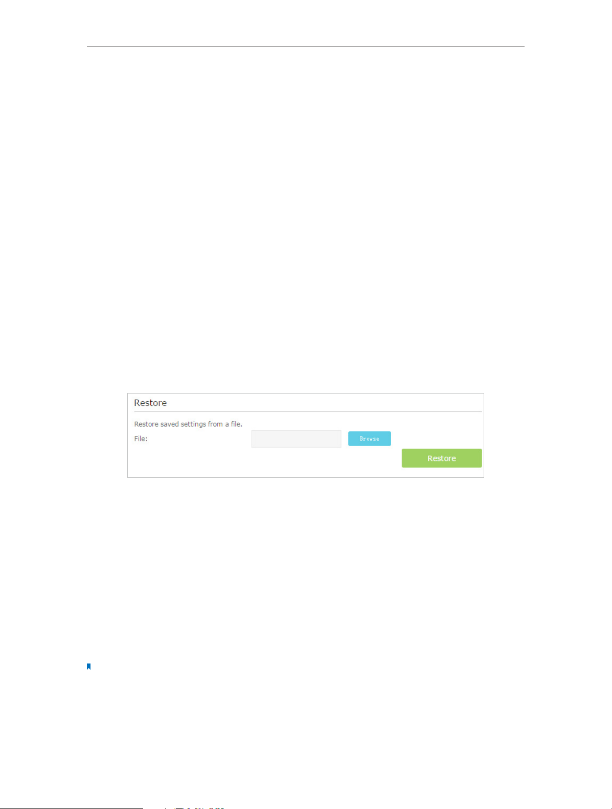
Chapter 13
Administrate Your Network
13. 3. Back up and Restore Configuration Settings
The configuration settings are stored as a configuration file in the router. You can back
up the configuration file to your computer for future use and restore the modem router
to a previous settings from the backup file when needed. Moreover, if needed you can
erase the current settings and reset the modem router to the default factory settings.
To back up configuration settings:
1. Visit http://tplinkmodem.net, and log in with the password you set for the modem
router.
2. Click Advanced > System Tools > Backup & Restore page.
3. Click Backup to save a copy of the current settings to your local computer. A conf.
bin file will be stored to your computer.
To restore configuration settings:
1. Visit http://tplinkmodem.net, and log in with the password you set for the modem
router.
2. Click Advanced > System Tools > Backup & Restore page.
3. Click Browse to locate the previous backup configuration file, and click Restore.
4. Wait for the restoring and then the modem router will automatically reboot.
To reset the modem router to factory default settings:
1. Visit http://tplinkmodem.net, and log in with the password you set for the modem
router.
2. Click Advanced > System Tools > Backup & Restore page.
3. Click Factory Restore to reset the modem router.
4. Wait for the resetting and then the modem router will automatically reboot.
Note:
1. During the resetting process, do not turn off or reset the modem router.
2. We strongly recommend you back up the current configuration settings before resetting the modem router.
87
Page 92

Chapter 13
Administrate Your Network
13. 4. Change the Administrator Account
Admin account is used to log in to the modem router’s web-based management page.
You are required to set the admin account at first login. You can also change it on the
web page.
1. Visit http://tplinkmodem.net, and log in with the password you set for the modem
router.
2. Go to Advanced > System Tools> Administration page. Locate the Account
Management section.
3. Enter the old password. Enter the new password and enter again to confirm.
4. Click Save to make the settings effective.
13. 5. Local Management
You can control the local devices’ authority to manage the modem router via Local
Management feature. By default all local connected devices are allowed to manage the
modem router. You can also allow only one device to manage the modem router.
Follow the steps below to specify the local management.
1. Visit http://tplinkmodem.net, and log in with the password you set for the modem
router.
2. Go to Advanced > System Tools> Administration page. Locate the Local
Management section.
3. Keep the Port as the default setting. Enter the IP address or MAC address of the
local device to manage the modem router.
88
Page 93

Chapter 13
Administrate Your Network
4. Click Save to make the settings effective. Now only the device (192.168.1.100)
can manage the modem router. If you want that all local devices can manage the
modem router, just leave the IP/MAC Address field blank.
13. 6. Remote Management
By default, the remote devices are not allowed to manage the modem router from the
Internet.
Follow the steps below to allow remote devices to manage the modem router.
1. Visit http://tplinkmodem.net, and log in with the password you set for the modem
router.
2. Go to Advanced > System Tools> Administration page. Locate the Remote
Management section.
3. Tick the checkbox to enable Remote Management. Keep the Port as the default
setting. Leave the IP/MAC Address field blank. If you just want to allow a specific
device to manage the modem router, you can enter the IP address of the remote
device in the IP/MAC Address field.
4. Click Save to make the settings effective. Now, all devices on the Internet
can log in to http://modem router’s WAN IP address:port number (such as
http://113.116.60.229:80) to manage the modem router.
Tips:
1. You can find the WAN IP address of the router on Basic > Network Maps > Internet.
2. The router’s WAN IP is usually a dynamic IP. Please refer to Set up a Dynamic DNS Service Account if you want to log
in to the router through a domain name.
89
Page 94

Chapter 13
Administrate Your Network
13. 7. System Log
System Log can help you know what happened to your modem router, facilitating
you to locate the malfunctions. For example when your modem router does not work
properly, you will need to save the system log and send it to the technical support for
troubleshooting.
1. Visit http://tplinkmodem.net, and log in with the password you set for the modem
router.
2. Click Advanced > System Tools > System Log page.
To view the system logs:
1. Select the log Type. Select ALL to view all kinds of logs, or select DHCPD or IGMP to
view the specific logs.
2. Select the log Level and you will see the logs with the specific or higher levels.
3. Click Refresh to refresh the log list.
To save the system logs:
You can choose to save the system logs to your local computer or a remote server.
90
Page 95

Chapter 13
Click Save Log to save the logs in a txt file to your computer.
Click Log Settings to set the save path of the logs.
Administrate Your Network
• Save Locally: Select this option to cache the system log to the router’s local memory,
select the minimum level of system log to be saved from the drop-down list. The logs
will be shown in the table in descending order on the System Log page.
• Save Remotely: Select this option to send the system log to a remote server, select
the minimum level of system log to be saved from the drop-down list and enter the
information of the remote server. If the remote server has a log viewer client or a
sniffer tool implemented, you can view and analyze the system log remotely in realtime.
13. 8. Monitor the Internet Traffic Statistics
The Traffic Statistics page displays the network traffic of the LAN, WAN and WLAN sent
and received packets, allowing you to monitor the volume of Internet traffic statistics.
1. Visit http://tplinkmodem.net, and log in with the password you set for the modem
router.
2. Go to Advanced > System Tools > Statistics.
3. Toggle on Traffic Statistics, and then you can monitor the traffic statistics in Traffic
Statistics List section. This function is disabled by default.
91
Page 96

Chapter 13
Administrate Your Network
13. 9. CWMP Settings
The modem router offers CWMP feature. The function supports TR-069 protocol which
collects information, diagnoses the devices and configures the devices automatically
via ACS (Auto-Configuration Server).
1. Visit http://tplinkmodem.net, and log in with the password you set for the modem
router.
2. Go to Advanced > System Tools > CWMP Settings page.
92
Page 97

Chapter 13
Administrate Your Network
• Enable CWMP: Toggle On to enable the CWMP (CPE WAN Management Protocol)
feature.
• Inform: Enable this feature to send an Inform message to the ACS (Auto Configuration
Server) periodically.
• Inform Interval: Enter the time interval in seconds when the Inform message will be
sent to the ACS.
• ACS URL: Enter the web address of the ACS which is provided by your ISP.
• ACS Username/Password: Enter the username/password to log in to the ACS server.
• Interface used by TR-069 client: Select which interface to be used by the TR-069 client.
• Display SOAP messages on serial console: Toggle to enable or disable this feature.
• Connection Request Authentication: Select this checkbox to enable authentication
for the connection request.
• Connection Request Username/Password: Enter the username/password for the ACS
server to log in to the router.
• Connection Request Path: Enter the path for the ACS server to log in to the router.
93
Page 98

Chapter 13
Administrate Your Network
• Connection Request Port: Enter the port that connects to the ACS server.
• Connection Request URL: Enter the URL that connects to the ACS server.
• Get RPC methods: Click to get the methods to support CWMP.
Click Save to make the settings effective.
13. 10. SNMP Settings
SNMP (Simple Network Management Protocol) has been widely applied in the computer
networks currently, which is used for ensuring the transmission of the management
information between two nodes. In this way, network administrators can easily search
and modify the information on any node on the network. Meanwhile, they can locate
faults promptly and implement the fault diagnosis, capacity planning and report
generating.
An SNMP Agent is an application running on the modem router that performs the
operational role of receiving and processing SNMP messages, sending responses to the
SNMP manager, and sending traps when an event occurs. So a router contains SNMP
“agent” software can be monitored and/or controlled by SNMP Manager using SNMP
messages.
1. Visit http://tplinkmodem.net, and log in with the password you set for the modem
router.
2. Go to Advanced > System Tools > SNMP Settings page.
• Enable SNMP Agent: Toggle On to enable the built-in SNMP agent that allows
the router to operate as the operational role in receiving and processing of SNMP
94
Page 99

Chapter 13
Administrate Your Network
messages, sending responses to the SNMP manager, and triggering SNMP traps
when an event occurs.
• Read Community: Displays the default public community string that protects the
router from unauthorized access.
• Set Community: Displays the default read and write community string that protects
the router from unauthorized changes.
• System Name: Displays the administratively-assigned name for this managed device.
• System Description: Displays the textual description of the managed device. This
value should include the full name and version identification of the system’s hardware
type, software operating-system, and networking software.
• System Location: Displays the physical location of this device (e.g., telephone closet,
3rd floor).
• System Contact: Displays the textual identification of the contact person for this
managed device, together with information on how to contact this person.
• Trap Manager IP: Displays the IP address of the host to receive the traps.
You are suggested to keep the default settings. Click Save to make the settings effective.
95
Page 100

Appendix A: Specications
General
ANSI T1.413, ITU G.992.1, ITU G.992.3, ITU G.992.5,
Standards and
Protocols
Safety & Emission FCC, CE
IEEE 802.11a, IEEE 802.11b, IEEE 802.11g, IEEE 802.11n, IEEE 802.11ac, IEEE
802.3, IEEE 802.3u, IEEE802.3ab, TCP/IP, PPPoA, PPPoE, SNTP, HTTP, DHCP,
ICMP, NAT
Antenna
Ports
Network Medium
Data Rates
System Requirement
Antenna Type: Three detachable external dual band antennas
Antenna Gain: 3 × 2dBi for 2.4GHz and 3 × 3dBi for 5GHz
1 10/100/1000Mbps RJ45 WAN/LAN Port
3 10/100/1000Mbps RJ45 LAN Ports
1 RJ11 Port
1 USB 2.0 Port
10Base-T: UTP category 3, 4, 5 cable
100Base-TX: UTP category-5, 5e cable
1000Base-TX: UTP category-5, 5e cable
Max line length: 6.5Km
Downstream: Up to 24Mbps
Upstream: Up to 1Mbps
Windows 8.1/8/7/Vista/XP or Mac OS or Linux-based operating system
Microsoft Internet Explorer, Firefox, Chrome or Safari browser for web-based
configuration
Physical and Environment
Working
Temperature
Working Humidity 10% ~ 90% RH (non-condensing)
0℃ ~ 40℃
Storage Temperature
Storage Humidity 5% ~ 90% RH (non-condensing)
-40℃ ~ 70℃
 Loading...