

Page 1

Configuration Guide
Wireless Controller
AC50/AC500
1910012001 REV 1.0.0
Page 2

Content
About This Guide .................................................................................................................. 1
1 Quick Start ....................................................................................................................... 2
1.1 Determine the Network Topology ............................................................................................................ 2
1.1.1 Manage CAPs in the LAN ................................................................................................................................ 2
1.1.2 Manage CAPs in Different Network Segment ..................................................................................... 3
1.2 Log in to the AC ...............................................................................................................................................3
1.2.1 Preparations ........................................................................................................................................................... 3
1.2.2 Log in .......................................................................................................................................................................... 4
2 Status ................................................................................................................................ 6
2.1 System Status .................................................................................................................................................. 6
2.2 Client Status ...................................................................................................................................................... 7
2.3 AP Status ............................................................................................................................................................ 8
2.4 Authentication Status ....................................................................................................................................9
2.4.1 Authentication Status .......................................................................................................................................9
2.4.2 Non-sense Authenticated User ...............................................................................................................10
3 Network ..........................................................................................................................11
3.1 Interface........................................................................................................................................................... 11
3.2 DHCP Server .................................................................................................................................................. 12
3.2.1 DHCP Server ....................................................................................................................................................... 12
3.2.2 DHCP Client List ................................................................................................................................................ 14
3.2.3 Address Reservation ...................................................................................................................................... 14
3.3 VLAN ................................................................................................................................................................. 15
3.3.1 VLAN ........................................................................................................................................................................ 15
3.3.2 Ports .........................................................................................................................................................................17
3.3.3 Relations ................................................................................................................................................................ 18
3.4 Switch ............................................................................................................................................................... 19
Page 3

3.4.1 Statistics ................................................................................................................................................................ 19
3.4.2 Mirror .......................................................................................................................................................................20
3.4.3 Rate Control .........................................................................................................................................................20
3.4.4 Port Config ...........................................................................................................................................................21
3.4.5 Port Status ............................................................................................................................................................22
4 AP Control ......................................................................................................................23
4.1 AP Settings ..................................................................................................................................................... 23
4.2 AP Firmware Upgrade ................................................................................................................................. 26
4.3 AP Database ................................................................................................................................................... 27
4.4 Load Balancing .............................................................................................................................................. 28
5 Radio ................................................................................................................................ 30
5.1 Radio Settings ............................................................................................................................................... 30
5.2 Rate Settings ................................................................................................................................................. 33
5.3 Band Steering ................................................................................................................................................ 34
6 Wireless .......................................................................................................................... 37
6.1 Wireless Service ........................................................................................................................................... 37
7 Authentication ..............................................................................................................41
7.1 MAC Authentication .................................................................................................................................... 41
7.1.1 MAC Address ......................................................................................................................................................42
7.1.2 MAC Authentication ........................................................................................................................................ 43
7.2 Portal Authentication .................................................................................................................................. 44
7.2.1 Redirect Page ..................................................................................................................................................... 44
7.2.2 Web Authentication ........................................................................................................................................46
7.2.3 Configuring Web Authentication .............................................................................................................47
7.2.4 Onekey Online .................................................................................................................................................... 50
7.2.5 Remote Portal ..................................................................................................................................................... 51
7.2.6 Free Authentication Policy .......................................................................................................................... 53
7.2.7 Authentication Config .................................................................................................................................... 56
Page 4

7.3 User Management ....................................................................................................................................... 57
7.3.1 Authentication Server .................................................................................................................................... 59
7.4 Applications ................................................................................................................................................... 62
7.4.1 Application for Onekey Online ..................................................................................................................62
7.4.2 Application for Web Authentication ....................................................................................................... 65
8 Link Backup ................................................................................................................... 69
8.1 Dual-link Backup ........................................................................................................................................... 69
8.2 Application ...................................................................................................................................................... 70
9 System Tools ................................................................................................................ 73
9.1 Account ............................................................................................................................................................ 73
9.1.1 Account ..................................................................................................................................................................73
9.1.2 System Settings ................................................................................................................................................ 74
9.2 Administration ............................................................................................................................................... 74
9.2.1 Factory Default Restore ................................................................................................................................ 74
9.2.2 Backup & Restore ............................................................................................................................................. 75
9.2.3 Reboot .................................................................................................................................................................... 76
9.2.4 Firmware Upgrade ............................................................................................................................................ 76
9.3 Traffic Statistics ............................................................................................................................................ 77
9.4 Diagnostics ..................................................................................................................................................... 78
9.5 Time Settings ................................................................................................................................................. 79
9.6 System Log..................................................................................................................................................... 81
Page 5

About This Guide
This Configuration Guide provides information for managing AC500/AC50 Series Wireless
Controller. Please read this guide carefully before operation.
Intended Readers
This Guide is intended for network managers familiar with IT concepts and network
terminologies.
Conventions
When using this guide, please notice that features of the device may vary slightly
depending on the model and software version you have. All screenshots, images,
parameters and descriptions documented in this guide are used for demonstration only.
The information in this document is subject to change without notice. Every effort has
been made in the preparation of this document to ensure accuracy of the contents, but
all statements, information, and recommendations in this document do not constitute
the warranty of any kind, express or implied. Users must take full responsibility for their
application of any products.
In this Guide, the following conventions are used:
Notes contains suggestions or references that helps you make better use of your device.
For GUI, Menu Name > Submenu Name > Tab page indicates the menu structure. Network >
DHCP Server > DHCP Client List means the DHCP Client List page under the DHCP Server
menu option that is located under the Network menu.
Bold font indicates a button, a toolbar icon, menu or menu item.
More Information
The latest software and documentations can be found at Download Center at
http://www.tp-link.com/support
The Installation Guide (IG) can be found where you find this guide or inside the package
of the wireless controller.
Specifications can be found on the product page at http://www.tp-link.com.
A Technical Support Forum is provided for you to discuss our products at
http://forum.tp-link.com.
Our Technical Support contact information can be found at the Contact Technical
.
Support page at http://www.tp-link.com/support.
1
Page 6
1
Wireless Controller
Quick Start
The wireless controller (AC) is a device used for centralized management of access points
(APs). At present, the supported APs are TP-Link’s CAPs. The AC can configure CAPs
in batches using a web browser and conduct a real-time monitoring of each CAP in the
network. This AC supports AP automatic discovery, AP status monitoring, AP centralized
control, MAC filtering, radio management, load balance, dual-link backup and various
authentication types.
This wireless controller makes it easier to configure and manage dozens or hundreds of
CAPs in a large public environment, such as markets, hotels, companies and campuses,etc.
AC500 wireless controller supports to manage 500 CAPs at the same time and AC50
wireless controller supports 50 CAPs.
1.1 Determine the Network Topology
You can use the AC to centrally manage the CAPs in the same or different network
segment.
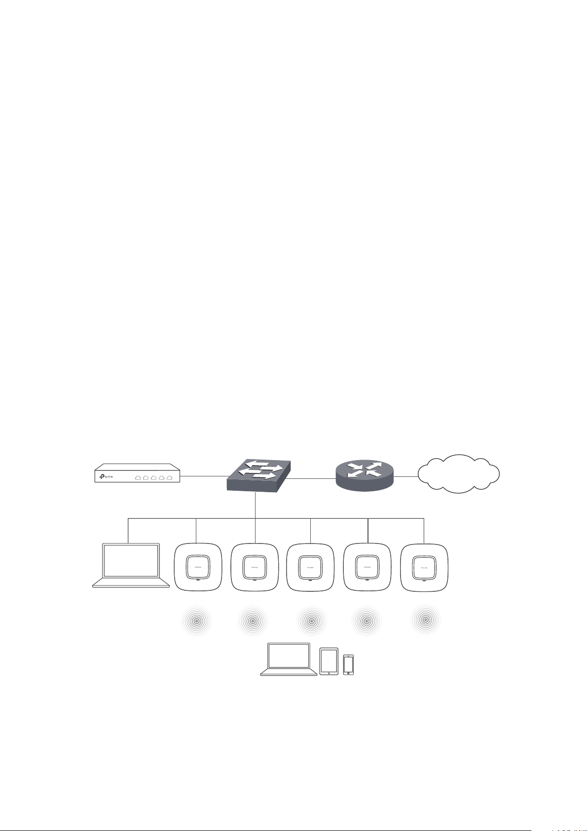
1.1.1 Manage CAPs in the LAN
If you want to manage the CAPs in the LAN, refer to the following network topology.
Router (DHCP Server)
LAN IP:192.168.0.1
Internet
CAP
IP: 192.168.0.100
Host A
IP: 192.168.0.200
Switch
Clients
2
Page 7
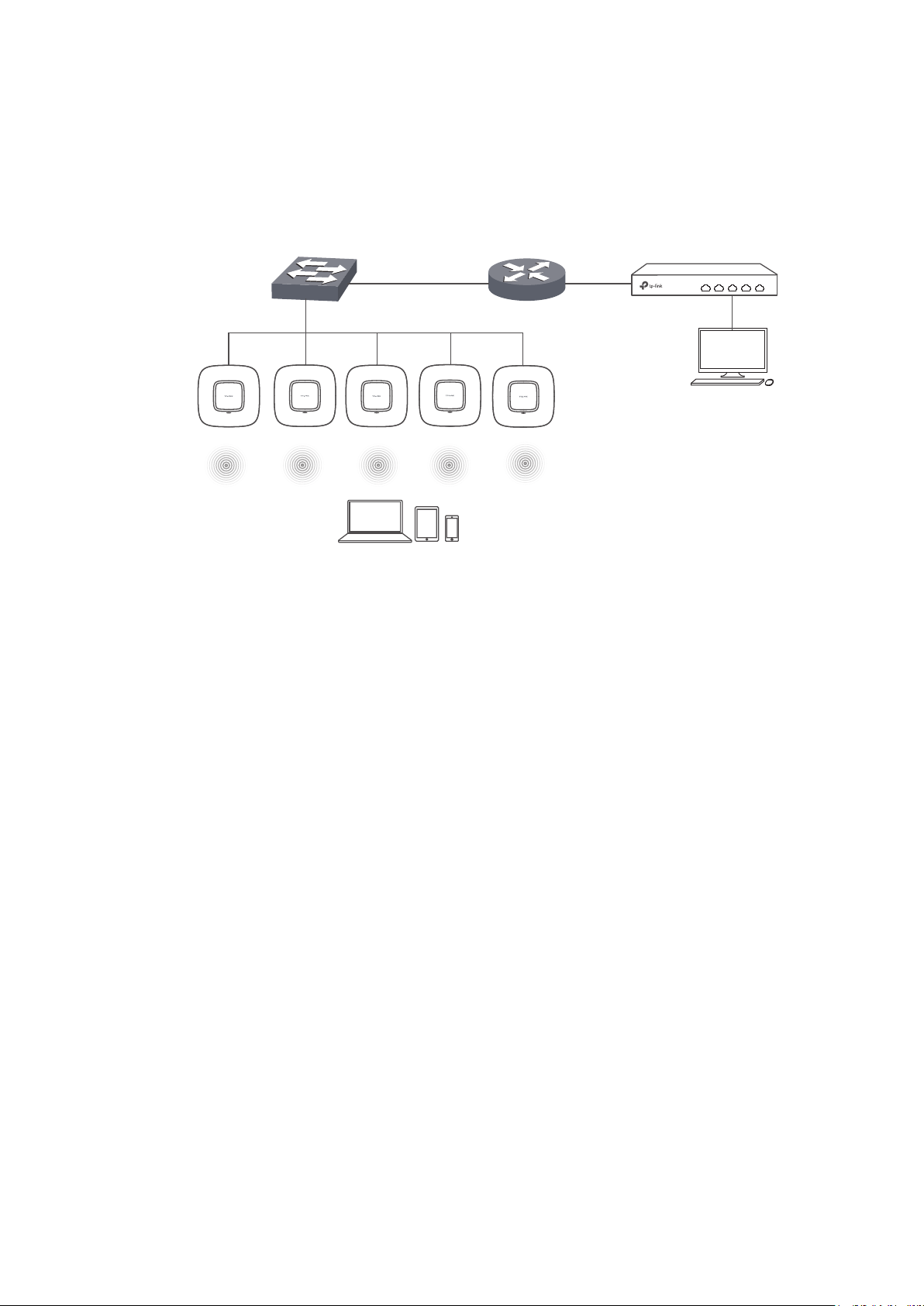
1.1.2 Manage CAPs in Different Network Segment
If the AC needs to manage CAPs in a different network segment, refer to the following
topology.
Switch
Router
1.1.1.2192.168.1.1
CAP
Clients
Wireless Controller
IP: 1.1.1.100
Host A
IP: 1.1.1.101
Note:
In this situation, the router acting as the CAPs' DHCP server should support option 60 and option138 in DHCP
settings.
1.2 Log in to the AC
1.2.1 Preparations
Before login, you should verify the following:
The AC is powered on and correctly connected. The management host is accessible to
the AC.
Specify the management host with a static IP address on the 192.168.0.x subnet (for
example, IP address 192.168.0.100 and subnet mask 255.255.255.0).
Operating System: Microsoft Windows XP/Vista/7/8/10.
Web Browser: Mozilla Firefox 32 (or above), Google Chrome 37 (or above), Opera 24 (or
above), or Microsoft Internet Explorer 8-11.
3
Page 8
1.2.2 Log in
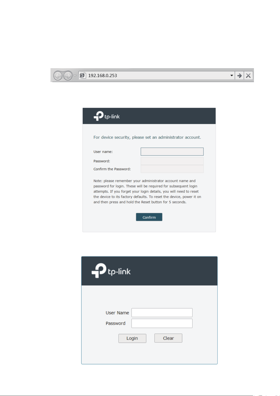
1 Open a web browser and enter 192.168.0.253 in the address field, then press Enter key.
Figure 1-1 Enter the IP Address
2 Create a username and a password for subsequent login attempts.
Figure 1-2 Create an account
3 Use the username and password set above to log in to the webpage.
Figure 1-3 Log in to the webpage
4
Page 9
4 After a successful login, the main page will appear as in the figure below, and you can
configure the function by clicking the setup menu on the left side of the screen.
Figure 1-4 Main Page
The wireless controller’s configuration files fall into two types: the running configuration file
and the start-up configuration file. After you perform configurations on the sub-interfaces
and click Save, the modifications will be saved in the running configuration file. However,
the configurations will be lost when the device reboots.
If you need to keep the configurations even if the device reboots, please use the function
to save the configurations in the start-up configuration file. Click Save Config on the topright of the interface, especially before you power off or reboot the device.
5
Page 10
2
Status
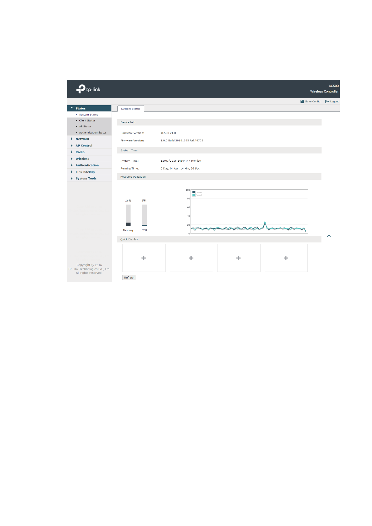
2.1 System Status
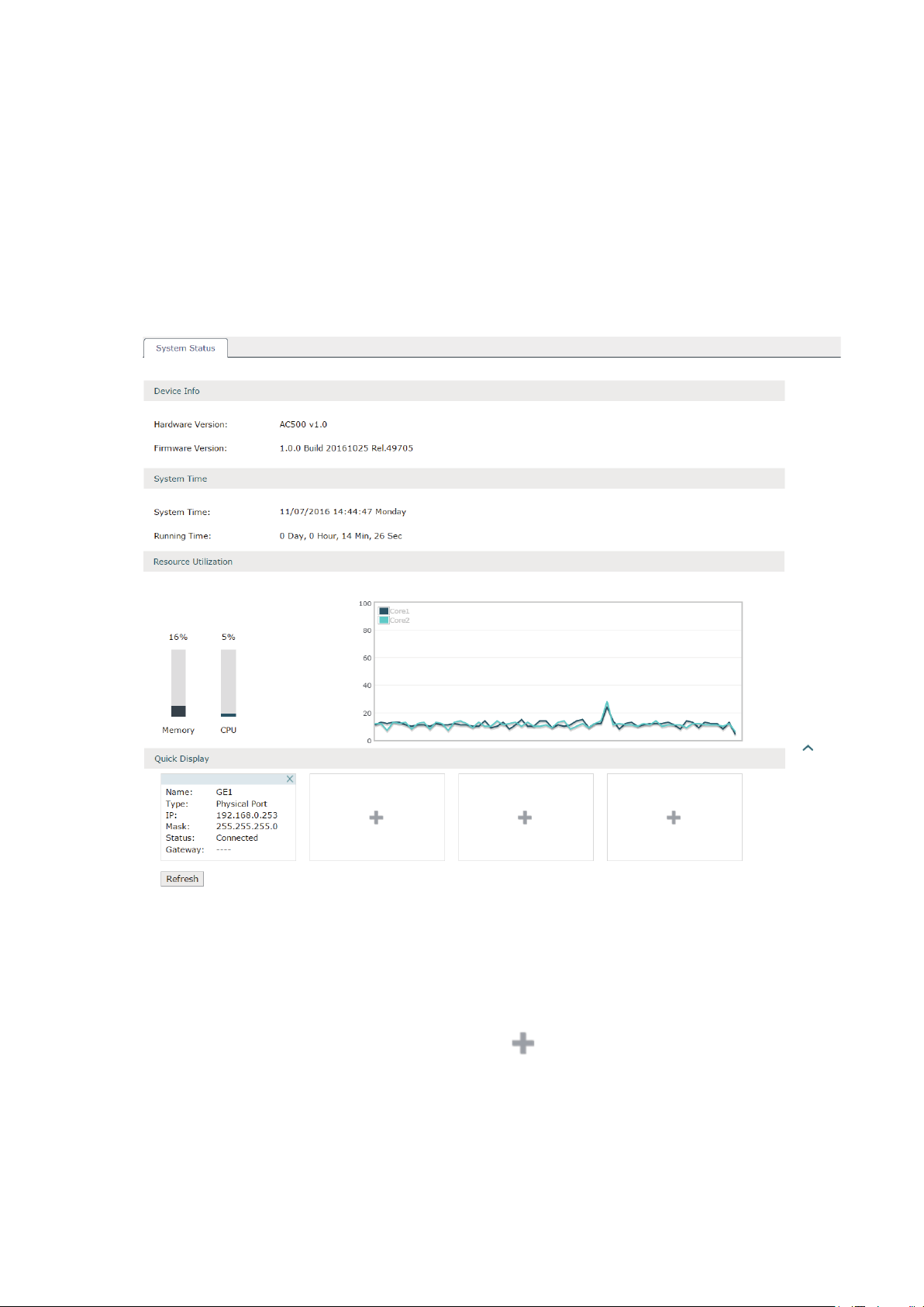
Choose the menu Status > System Status > System Status to load the following page.
Figure 2-1 System Status
In the Resource Utilization section, you can monitor the utilization of the memory and CPU.
It is recommended that the CPU utilization should be at about 50%. The CPU utilization
above 85% indicates that the AC is under a high load and above 95% means AC is
completely loaded. When the CPU utilization keeps at high loads, some function of the AC
may be abnormal. Please check to find the real reason.
In the Quick Display section, click the button
basic information such as interface name, type and IP address will be shown in this section.
6
to select the desired interface and its
Page 11
2.2 Client Status
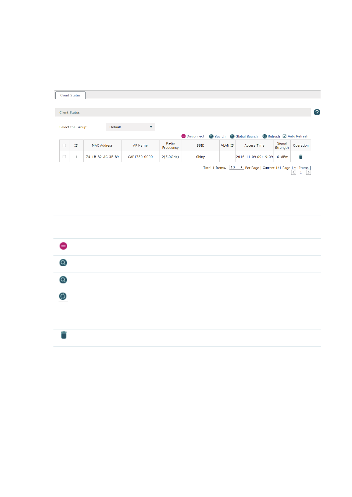
Choose the menu Status > Client Status > Client Status to load the following page.
Figure 2-2 Client Status
You can check the information of the connected clients on this page. Select the desired
clients by checking the boxes in front of the entries. Click the buttons above the list for
additional operations.
Select the Group Select the group from the drop-down list to see the clients' information in the
corresponding group.
Disconnect
Search
Global Search
Refresh
Auto Refresh Check the box to enable the Auto Refresh function. With it enabled, the list will
Disconnect one or more clients from the AP(s).
Search the specified clients in the list.
Search the specified clients globally.
Refresh the list manually.
refresh every few seconds automatically.
Disconnect the client from the AP in this corresponding entry.
7
Page 12
2.3 AP Status
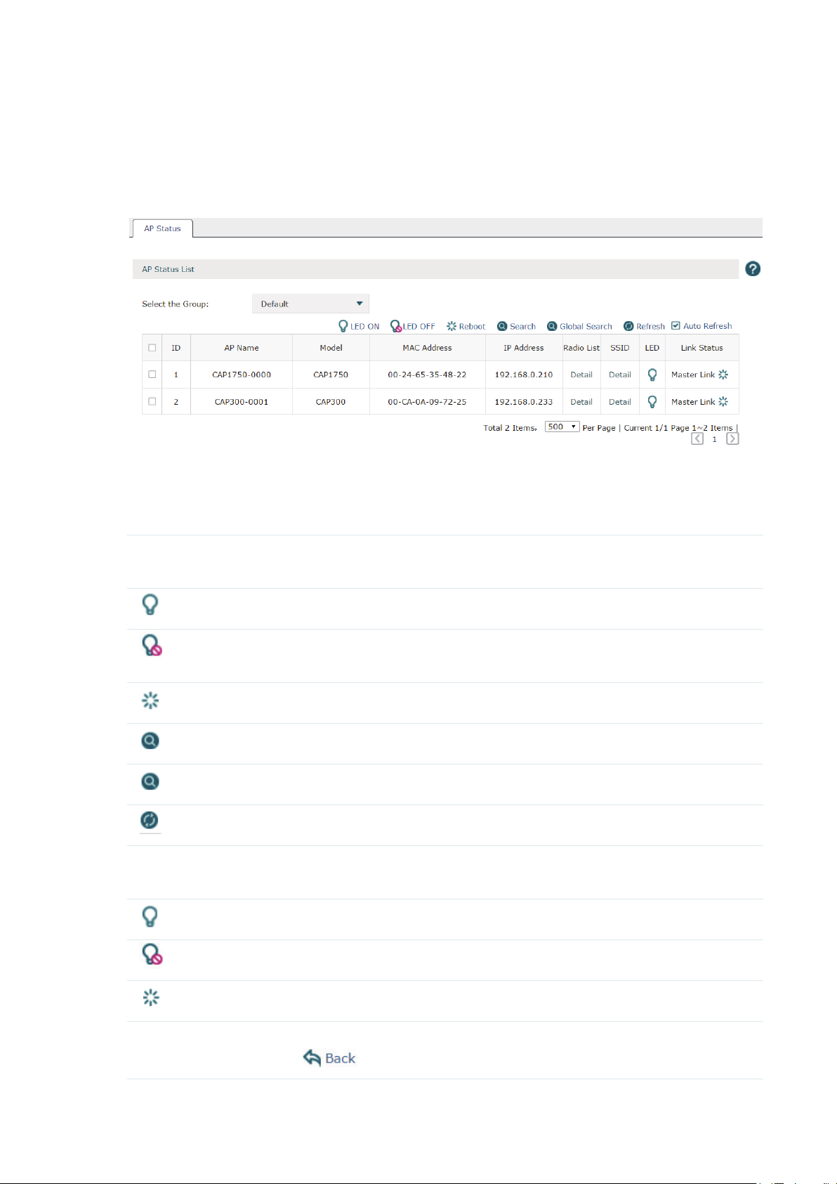
Choose the menu Status > AP Status > AP Status to load the following page.
Figure 2-3 AP Status
The information of the connected CAPs will be displayed in this section.
Select the desired
CAPs by checking the boxes in front of the entries. Click the buttons above the list for
additional operations.
Select the Group Select the group from the drop-down list to see the CAPs' information in the
corresponding group.
LED ON
LED OFF
Reboot
Search
Global Search
Refresh
Auto Refresh Check the box to enable the Auto Refresh function. With it enabled, the list will
Select the corresponding CAPs and click this button to turn on their LEDs.
Select the corresponding CAPs and click this button to turn off their LEDs. For
example, if the CAP's LED disturbs you at night, you can turn off it.
Select the corresponding CAPs and click this button to reboot them.
Search the specified clients in the list.
Search the specified clients globally.
Refresh the list manually.
refresh every few seconds automatically.
It indicates the LED is on. you can click the icon to turn off it.
It indicates the LED is off. you can click the icon to turn on it.
Click this icon to reboot the CAP.
Detail Click Detail to check the information of the radio list and SSID and click
to return.
8
Page 13
2.4 Authentication Status
2.4.1 Authentication Status
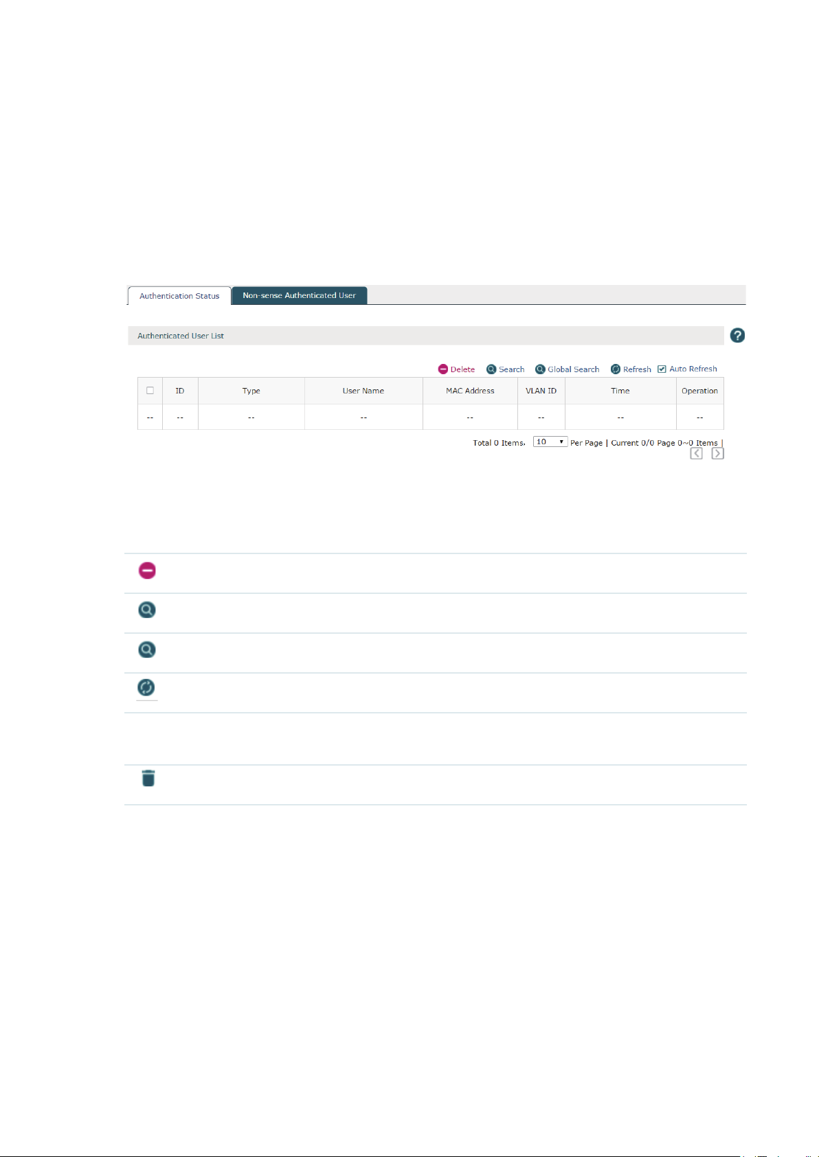
Choose the menu Status > Authentication Status > Authentication Status to load the
following page.
Figure 2-4 Authentication Status
You can check the information of the authentication status on this page. Select the desired
users by checking the boxes in front of the entries. Click the buttons above the list for
additional operations.
Delete
Search
Global Search
Refresh
Auto Refresh Check the box to enable the Auto Refresh function. With it enabled, the list will
Delete the users from the authentication list.
Search the specified users in the list.
Search the specified users globally.
Refresh the list manually.
refresh every few seconds automatically.
Disconnect the client from the AP in this corresponding entry.
9
Page 14
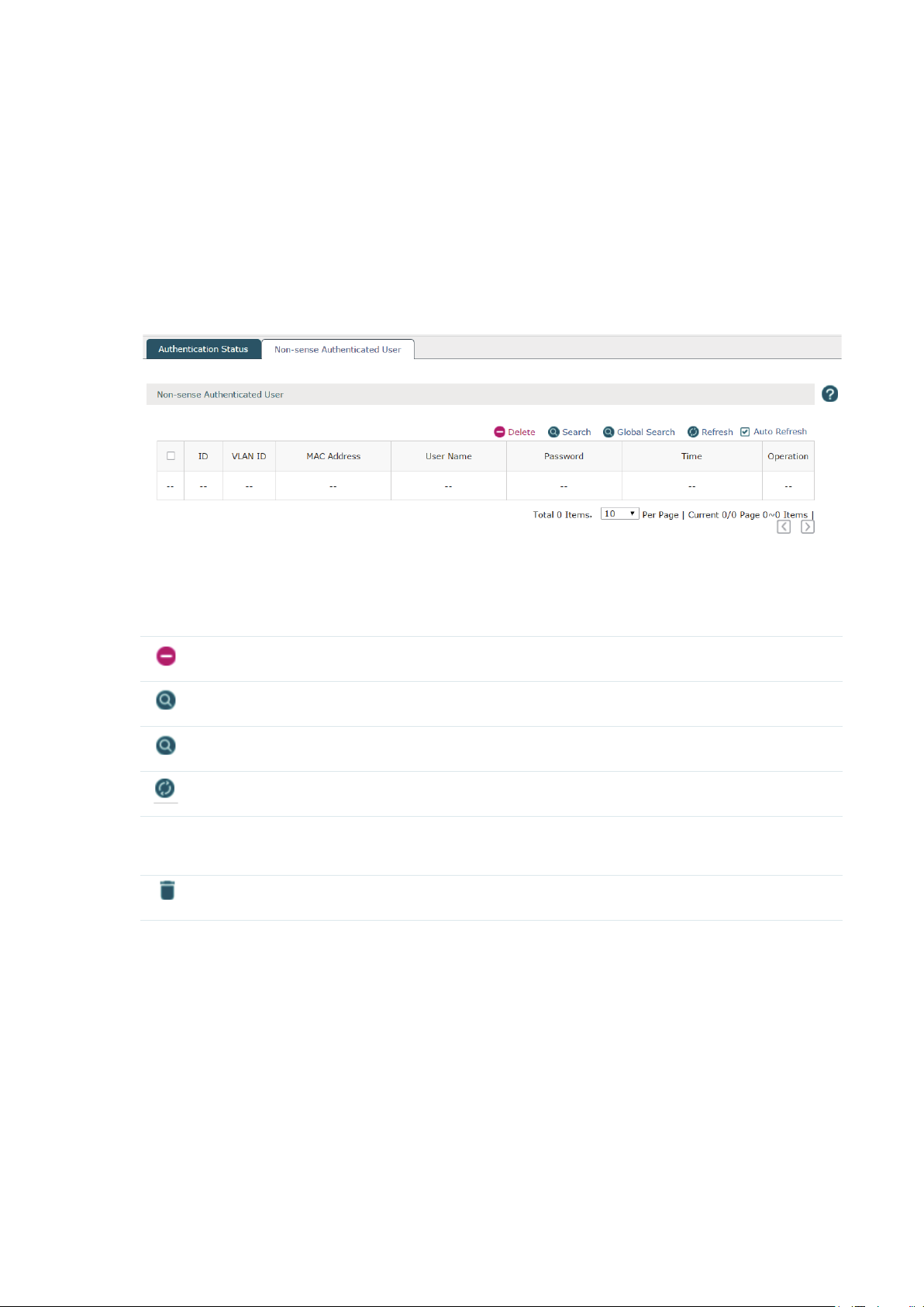
2.4.2 Non-sense Authenticated User
Non-sense authenticated users are users who have passed the authentication, leave the
wireless network and then join the wireless network again. If the time they left is within the
time threshold set by the AC, they don’t have to re-authenticate.
Choose the menu Status > Authentication Status > Non-sense Authenticated User to load
the following page.
Figure 2-5 Non-sense Authenticated User
You can check the information of the non-sense authenticated users on this page. Select
the desired users by checking the box in the front of the entries. Click the buttons above
the list for additional operations.
Delete
Search
Global Search
Refresh
Auto Refresh Check the box to enable the Auto Refresh function. With it enabled, the list will
Delete the users from the authentication list.
Search the specified users in the list.
Search the specified users globally.
Refresh the list manually.
refresh every few seconds automatically.
Disconnect the client from the AP in this corresponding entry.
10
Page 15
3
Network
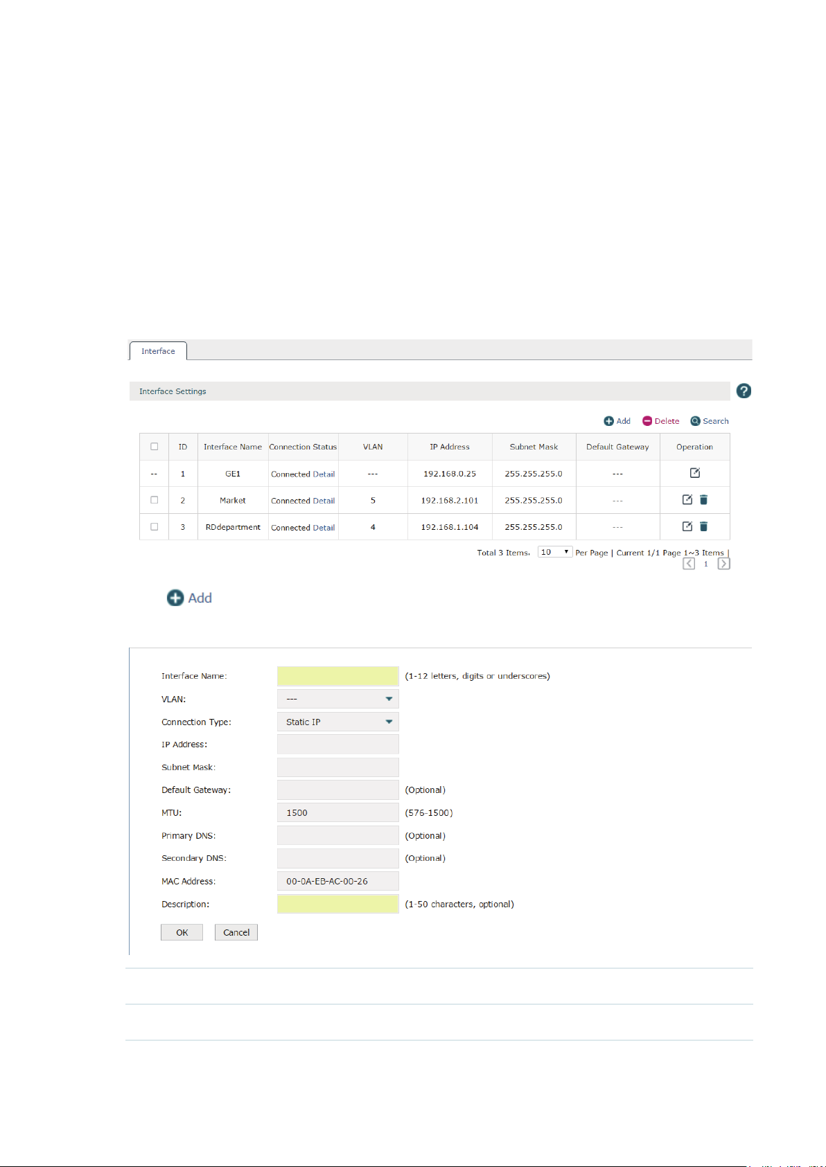
3.1 Interface
Choose the menu Network > Interface > Interface to load the following page. On this page
you can create a logical interface and specify it to a specified VLAN. Please refer to
to set VLANs first.
VLAN
Figure 3-1 Interface
3.3.1
Click to create a new interface. The page will be shown as below.
Figure 3-2 Add an Interface
Interface Name Specify a name for the interface to make it easier to search for and manage.
VLAN Specify a VLAN for the interface.
11
Page 16
Connection Type Select the connection type for the interface. Only static IP is supported at
present.
IP Address Specify an IP address for the interface.
Subnet Mask Specify a subnet mask for the interface.
Default Gateway (Optional) Specify a default gateway for the interface.
MTU Specify the MTU (Maximum Transmission Unit) for the interface. Its value is
between 576 to 1500 and 1500 by default.
Primary DNS (Optional) Specify the primary DNS server for the interface.
Secondary DNS (Optional) Specify the secondary DNS server for the interface.
MAC Address The MAC address is filled automatically. You can modify it manually.
Description Specify a description for the entry to make it easier to search for and manage.
Click OK to finish the settings.
3.2 DHCP Server
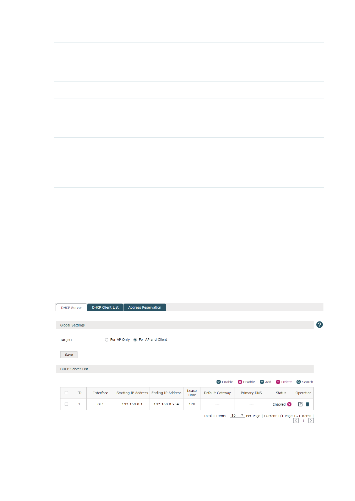
3.2.1 DHCP Server
Choose the menu Network > DHCP Server > DHCP Server to load the following page.
Figure 3-3 DHCP Server
DHCP (Dynamic Host Configuration Protocol) allows the wireless controller to assign IP
addresses, subnet masks, default gateways and other IP parameters to CAPs and clients
12
Page 17
that request this information. In the global settings you can select that the DHCP server
assigns IP parameters to AP only or both AP and client.
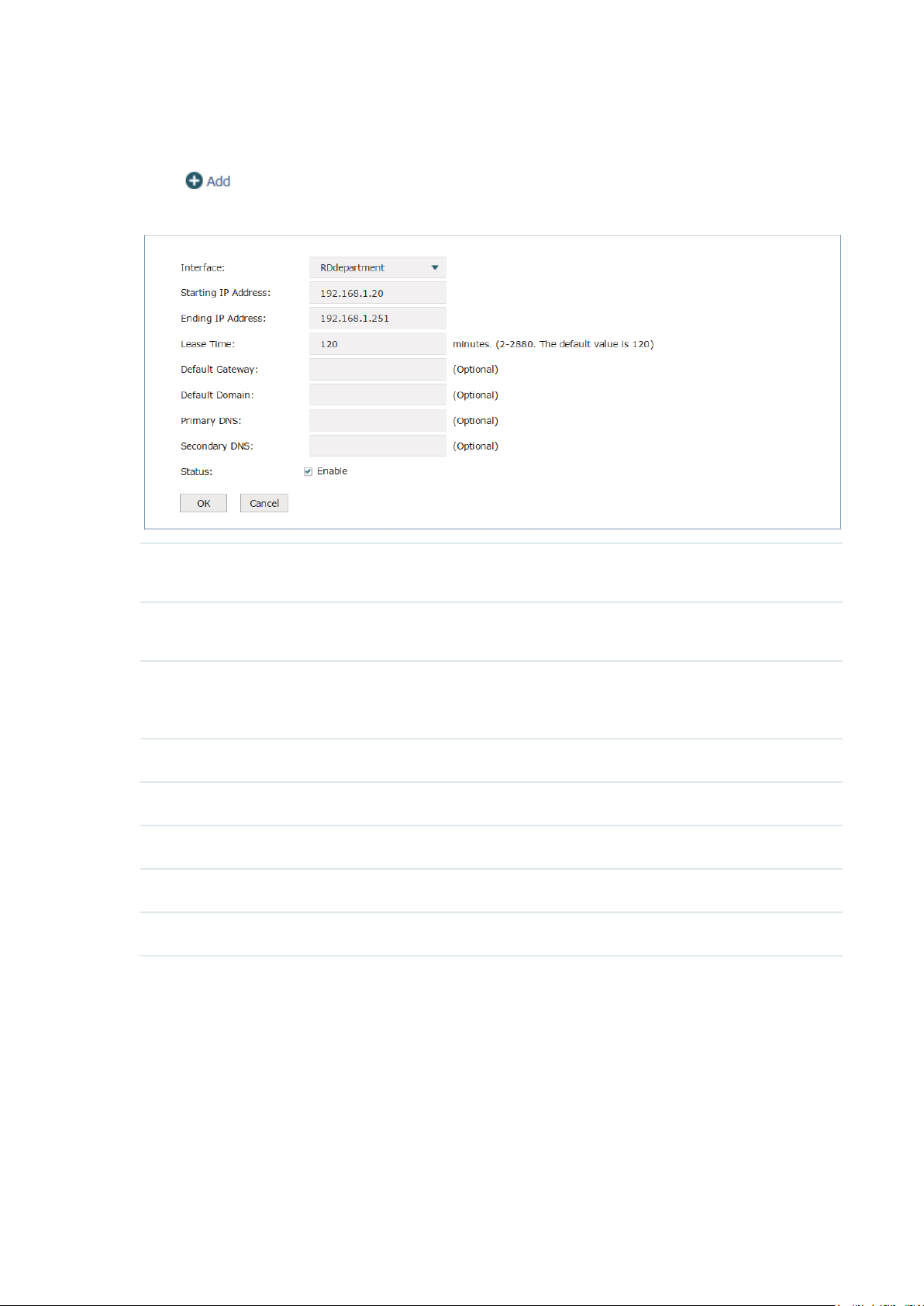
Click
Figure 3-4 Add a DHCP Server
Interface Select the interface which you want to create the DHCP server for. Refer to
Starting/Ending IP
Address
to create a DHCP server. The page will be shown as below.
Interface
Specify the starting IP address and ending IP address of the DHCP server IP
pool. The IP pool should be in the same segment with the interface IP address.
to set the interface first.
3.1
Lease Time Enter the time duration of the IP address assigned by the DHCP server between
2 and 2880 minutes. The default is 120 minutes. Before the time is up, DHCP
server would not assign this IP address to other APs or clients.
Default Gateway Optional: Specify the IP address of gateway for the server.
Default Domain Optional: Specify the domain of for the server.
Primary DNS Optional: Specify the primary DNS server for the server.
Secondary DNS Optional: Specify the secondary DNS server for the server.
Status Check the box to enable the DHCP service.
Click OK to finish the settings.
13
Page 18
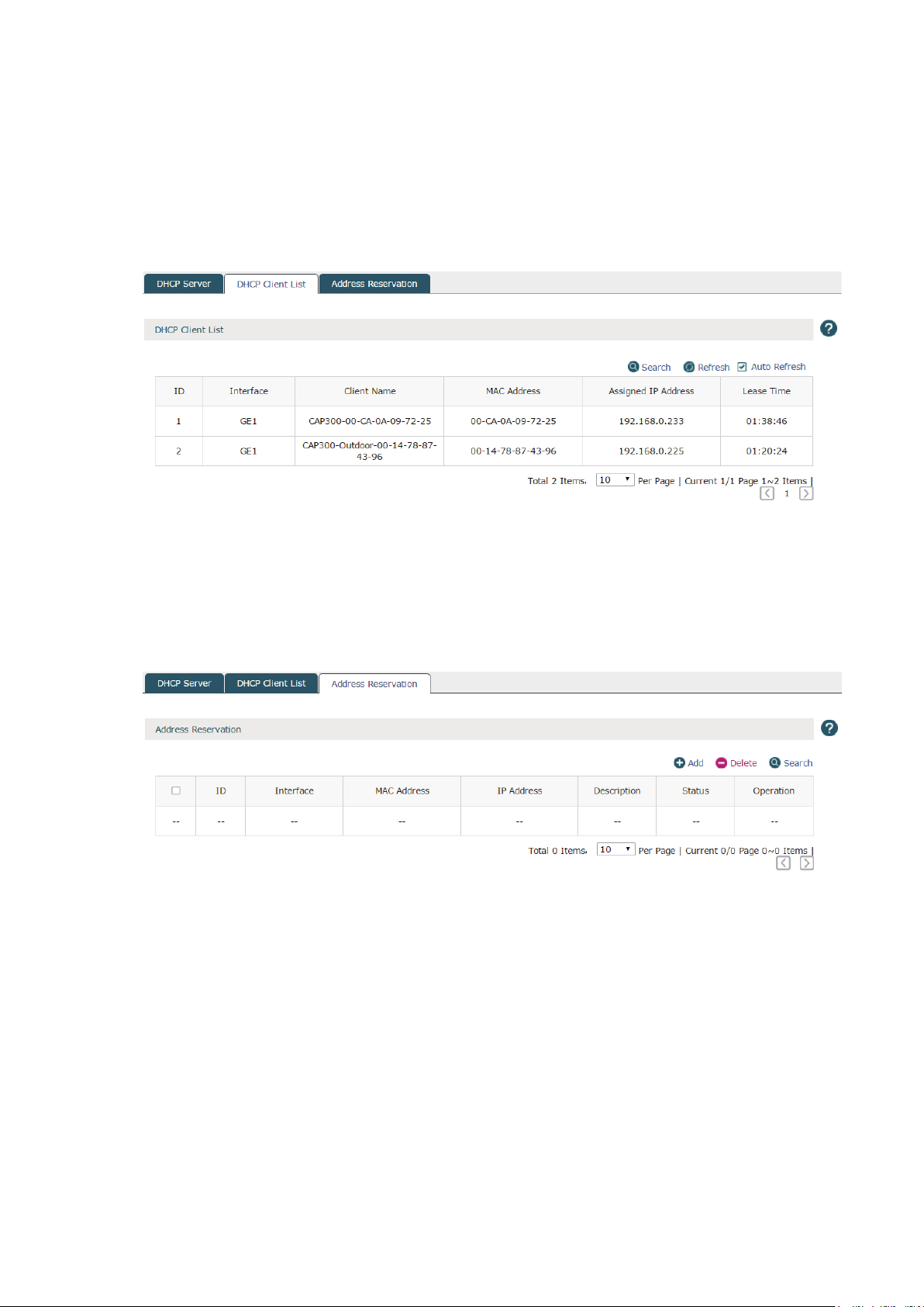
3.2.2 DHCP Client List
Choose the menu Network > DHCP Server > DHCP Client List to load the following page.
The list displays the information such as the IP address, MAC address and lease time of the
connected clients.
Figure 3-5 DHCP Client List
3.2.3 Address Reservation
Choose the menu Network > DHCP Server > Address Reservation to load the following
page.
Figure 3-6 Address Reservation
If the CAP or client requires a static IP address, you can manually reserve an IP address
for it. Once reserved, the IP address will only be assigned to the same client by the DHCP
server.
14
Page 19
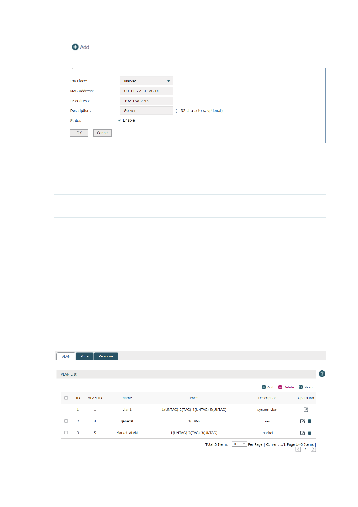
Click to create an IP address reservation.
Figure 3-7 Create an IP Address Reservation
Interface Select the interface which the CAP or client requiring the static IP address
belongs to. Refer to
MAC Address Enter the MAC address of the specified AP or client to which you want to assign
the static IP address.
IP Address Specify a static IP address to the specified AP or client. The IP address should
be in the same segment as the interface.
3.1 Interface
to set the interface first.
Description Specify a description for the entry to make it easier to search for and manage.
Status Check the box to enable the address reservation.
Click OK to finish the settings.
3.3 VLAN
3.3.1 VLAN
Choose the menu Network > VLAN > VLAN to load the following page.
Figure 3-8 VLAN
15
Page 20
VLAN (Virtual Local Area Network) is a network technique that solves broadcasting issues
in local area networks. A local area network is partitioned into several VLANs, and all VLAN
traffic remains within its VLAN. Therefore, you can group and isolate APs and clients to
enhance network security. VLANs group devices logically instead of physically, so devices
in the same VLAN can be located in different places.
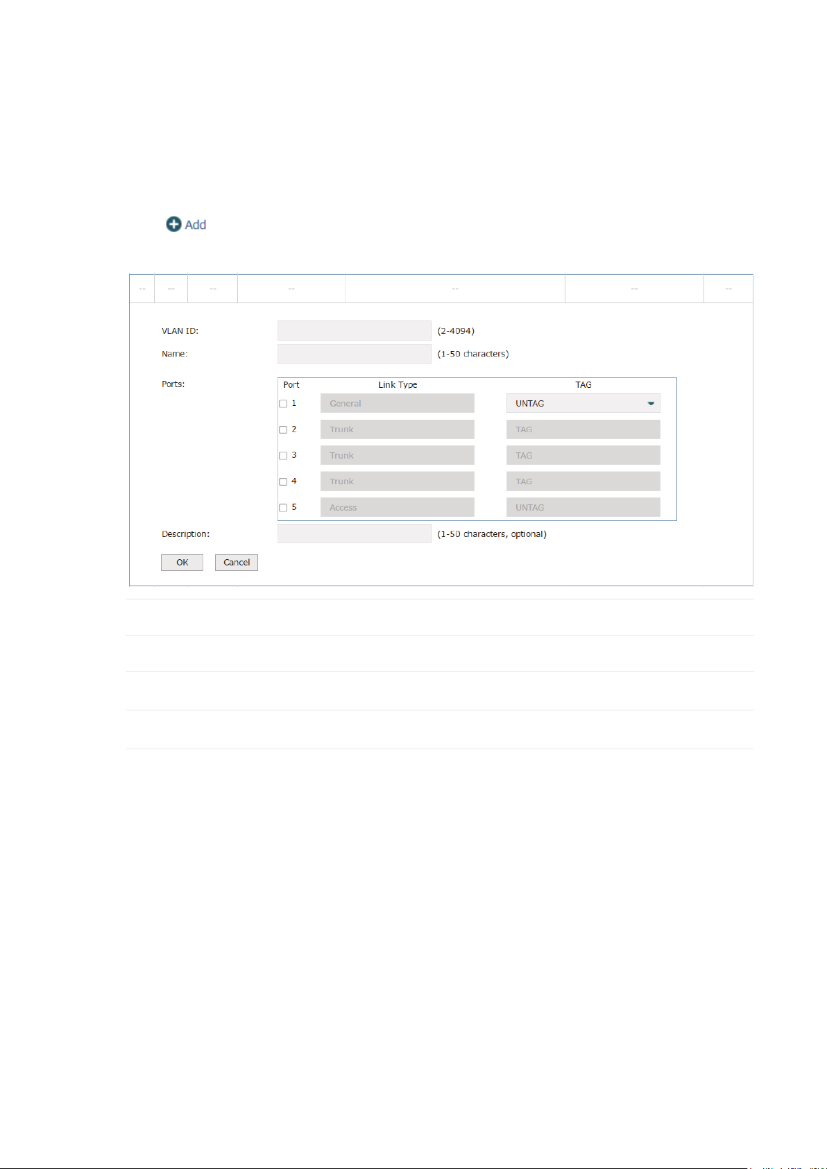
Click
Figure 3-9 Create a VLAN
VLAN ID Specify a VLAN ID between 2 to 4094.
to create a VLAN.
Name Specify an easy-to-remember name for the VLAN.
Ports Select the ports that belong to the VLAN.
Description Specify a description for the entry to make it easier to search for and manage.
Click OK to finish the settings.
16
Page 21
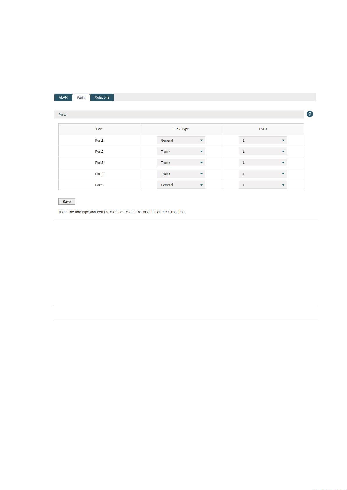
3.3.2 Ports
Choose the menu Network > VLAN > Ports to load the following page. Specify the link type
and PVLD for each port. The link type and PVID can not be modified at the same time.
Figure 3-10 Ports
Link Type The ports can be divided into three link types:
Access: The access port can be added in a single VLAN, and the egress rule
of the port is UNTAG. The PVID is same as the current VLAN ID. If the current
VLAN is deleted, the PVID will be set to 1 by default.
Trunk: The trunk port can be added in multiple VLANs. The egress rule of the
port is UNTAG if the arriving packet’s VLAN tag is the same as the port’s PVID,
otherwise the egress rule is TAG. The PVID can be set as the VID number of any
valid VLAN.
General: The general port can be added in multiple VLANs and set various
egress rules according to the different VLANs. The default egress rule is
UNTAG. The PVID can be set as the VID number of any valid VLAN.
PVID Enter the VLAN ID of the port.
Note:
AC50 doesn't include a General port link type.
17
Page 22
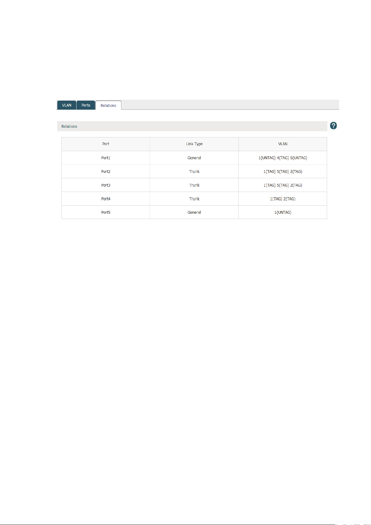
3.3.3 Relations
Choose the menu Network > VLAN > Relations to load the following page. This list displays
the relations among ports, link types and VLANs.
Figure 3-11 Relations
18
Page 23
3.4 Switch
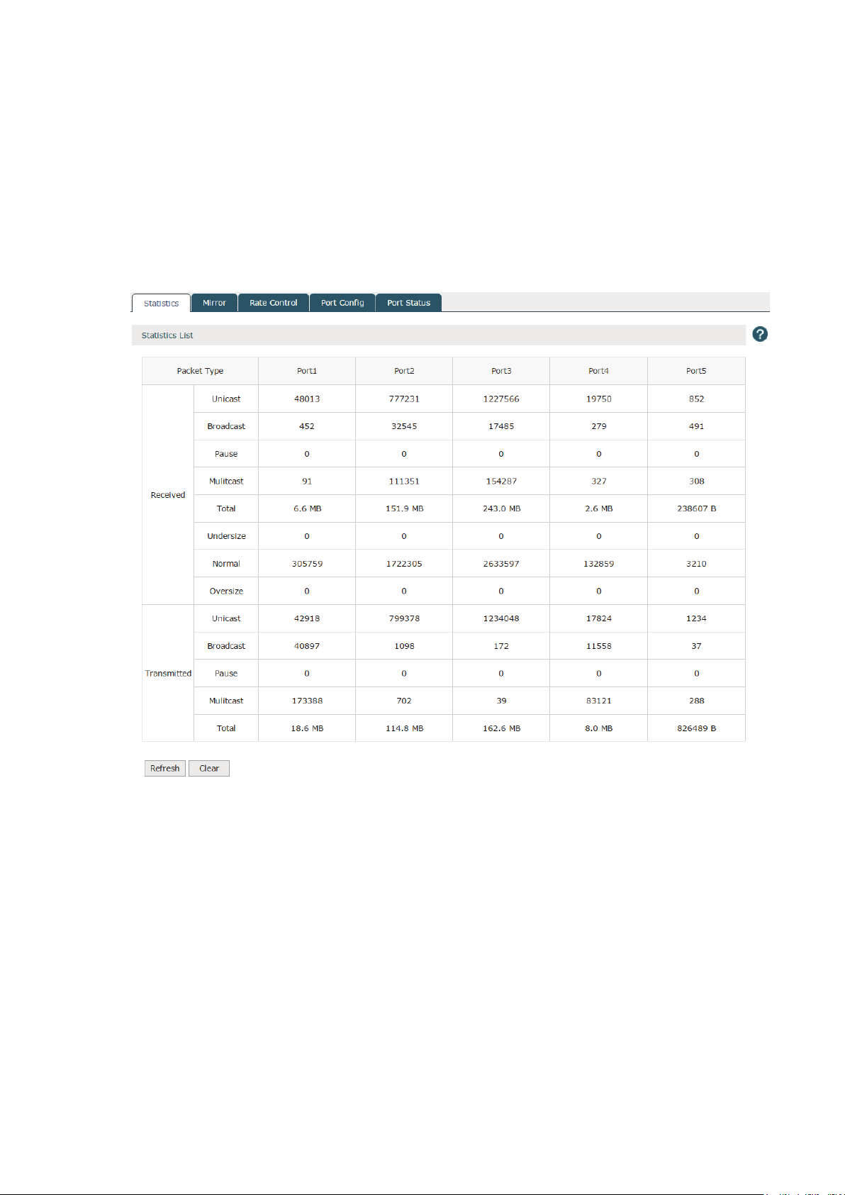
3.4.1 Statistics
Choose the menu Network > Switch > Statistics to load the following page. The statistics
list displays the information of data packets received or transmitted by each port.
Figure 3-12 Statistics
19
Page 24
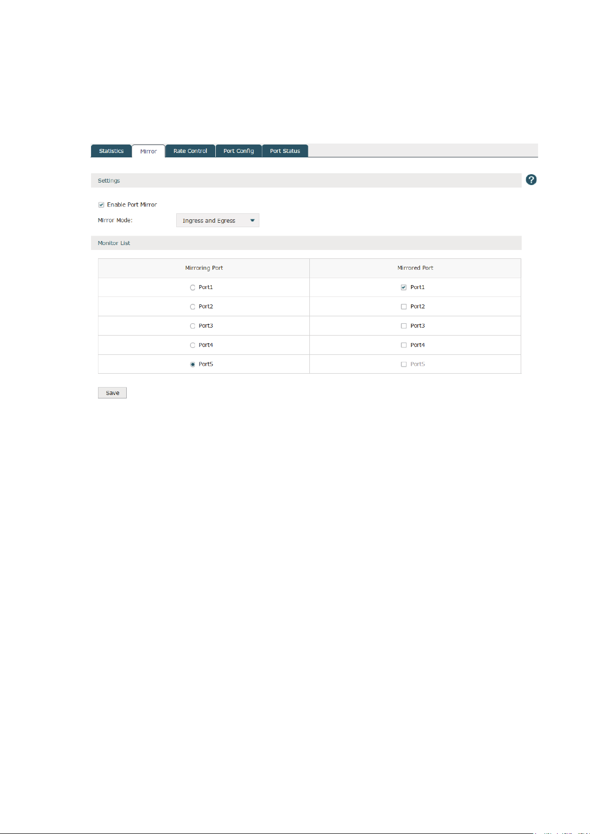
3.4.2 Mirror
Choose the menu Network > Switch > Mirror to load the following page.
Figure 3-13 Mirror
Check the box to enable the Port Mirror function. There are three port mirror modes as
follows.
Ingress and egress: When this mode is selected, both the incoming and outgoing packets
through the mirrored port will be copied to the mirroring port.
Ingress: When this mode is selected, the incoming packets received by the mirrored port
will be copied to the mirroring port.
Egress: When this mode is selected, the outgoing packets sent by the mirrored port will be
copied to the mirroring port.
A port cannot be set as the mirrored port and the mirroring port simultaneously. Only one
mirroring port can be set.
3.4.3 Rate Control
Choose the menu Network > Switch > Rate Control to load the following page. Here
you can control the data transfer rate for each port. Check boxes to manually enter the
corresponding rates.
Note:
The data transfer rate ranges from 1 to 100Mpbs for AC50, and from 1 to 1000Mpbs for AC500.
20
Page 25
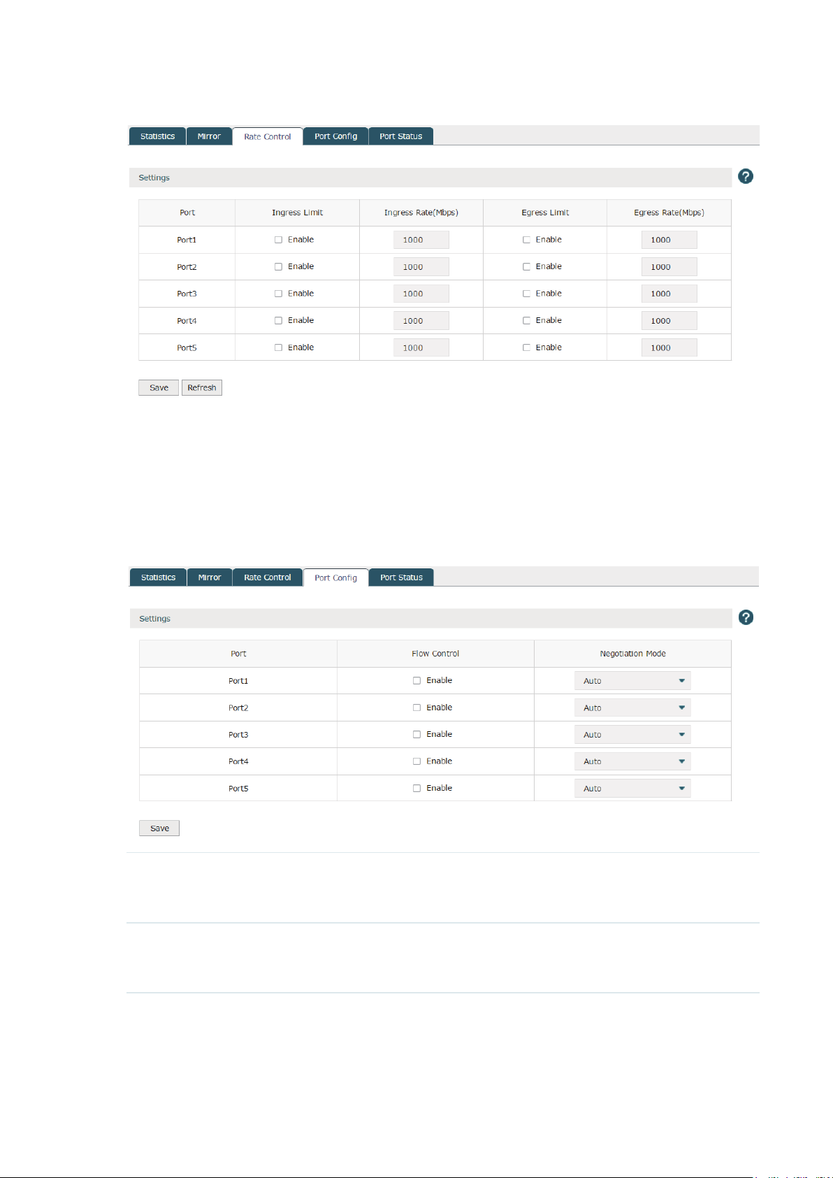
Figure 3-14 Rate Control
Click Save to finish the settings.
3.4.4 Port Config
Choose the menu Network > Switch > Port Config to load the following page.
Figure 3-15 Port Cofig
Flow Control With this option enabled, the device synchronizes the data transmission speed
with the peer device, thus avoiding the packet loss caused by congestion. By
default, it is disabled.
Negotiation Mode Select the Negotiation Mode for the port including auto and duplex mode.
Duplex mode includes 10M Half-duplex, 10M Full-duplex, 100M Half-duplex,
100M Full-duplex and 1000M Full-duplex.
Note:
The AC50 doesn't support 1000M Full-duplex.
21
Page 26
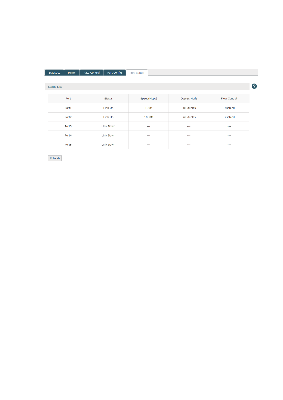
3.4.5 Port Status
Choose the menu Network > Switch > Port Status to load the following page.
Figure 3-16 Port Status
This page displays the connection status, speed, duplex mode and flow control status of
each port.
Disabled: The port is disabled.
Link down: The port is enabled but with physical connection.
Link up: The Port is enabled and connected normally.
Note:
The data transfer rate ranges from 1 to 100Mpbs for AC50, and from 1 to 1000Mpbs for AC500. AC50 doesn't
support 1000M Full-duplex.
22
Page 27

4
AP Control
4.1 AP Settings
Choose the menu AP Control > AP Settings > AP Settings to load the following page.
Figure 4-1 AP Settings
In the global settings, check the Reboot Schedule box and then the Lock to AC
Automatically box to enable the corresponding function. Click Save to complete.
Reboot Schedule With the reboot schedule enabled, all connected APs will reboot at the
specified time.
Reboot Date Select the date to reboot the APs. If you want to reboot the APs everyday,
please select everyday in the list.
Reboot Time Specify the reboot time to reboot the APs in the format of HH/MM/SS.
Lock to AC
Automatically
Click to create a new group. The following figure will be shown. Specify a group
name in the field and click OK.
With the lock to AC automatically enabled, all the APs entries will be locked to
AC automatically once APs connect to the AC. The unlocked AP entries will
disappear when the AC reboots.
23
Page 28

Figure 4-2 Add a group
In the group list, click the numbers at the Group Statistics Information row. The group
information will be shown as below. Click the buttons above the list for additional
operations.
Figure 4-3 Group statistics information
Back to Group List
Move to Other
Group
Lock to AC
Bulk Edit
Search
Intra Group Search
Click this button to return to the group list.
Select the corresponding entries and click this button to move them to your
desired group.
Select the corresponding entries and click this button to lock the APs to the
AC.
Select the corresponding entries and click this button to bulk edit the APs' AP
keep-alive time, client keep-alive time and client idle time. Refer to the following
introduction below the table for details.
Click this button to search the specified AP(s) on the current page.
Click this button to search the specified AP(s) in all the AP entries without the
limitation of groups.
24
Page 29

Click at the Operation row of the list. The following figure will be shown.
Figure 4-4 AP Settings
Name Specify the AP's name.
AP Keep-alive Time Specify the time interval for the AP sending echo packets to the AC. AC can
detect whether the AP is online or not by receiving the echo packets.
Client Keep-alive Time Specify the time interval for the client sending heartbeat packets to the AP. APs
can detect whether the client is online or not by receiving heartbeat packets.
Client Idle Time Specify a time interval for the client idle time. The clients will be disconnected
from the AP if there is no data transmission between AP and clients for the
specific time interval.
25
Page 30

4.2 AP Firmware Upgrade
Choose the menu AP Control > AP Firmware Upgrade > AP Firmware Upgrade to load the
following page.
With it enabled, import the correct firmwares and set the starting upgrade time. The
connected APs will start to upgrade at the specified time. If it is disabled, the APs that
haven’t started upgrading will not be upgraded.
Figure 4-5 AP Firmware Upgrade
AP Model Displays the AP model.
Hardware Version Displays the current hardware version.
Firmware Version Displays the imported firmware version.
Upgrade Starting Time After the upgrade file has been imported successfully, specify the upgrade
starting time. With upgrade enabled, the APs of this model will automatically
upgrade using the upgrade file.
Upgrade Process Displays the upgrade process. The format is X/Y/Z, which means there are Z
APs of this model in the system, with Y APs waiting to upgrade and X APs have
upgraded successfully. Click the numbers to check each AP's upgrade status.
Upgrade Failure Displays the number of APs which failed to upgrade. Click the number to check
the detailed log information.
26
Page 31

Upgrade Status Displays the upgrade status of current APs of this model. Click to check the
detailed upgrade information of each AP of this model.
Latest: There is no AP of the current model to be upgraded.
Waiting: APs of the current model are waiting to be upgraded.
Upgrading: Some APs of the current model are upgrading.
Completed: All APs of the current model are upgraded.
Terminated: The upgrade was disabled while the AP was waiting to upgrade.
The AP's upgrade process is terminated. When the upgrade is enabled again,
the status of the AP will change to "Waiting".
Operation Click Import to import the upgrade firmware into the system.
Click Delete to delete the firmware.
Note:
1. Only one model can upgrade at a time.
2. When the AC reboots or the CAPs reboot automatically, the CAPs can only upgrade after ten minutes.
3. The parameter of upgrade process and upgrade failure will be cleared when the AC reboots.
4. The standby link doesn't support upgrade schedule.
4.3 AP Database
Import the AP database file to support the identification and management of new AP
models on this page. When there is an undetected AP model connecting to the AC, the AC
should import the latest AP database to identify the new AP models.
Choose the menu AP Control > AP Database > AP Database to load the following page.
Figure 4-6 AP Settings
Current Version Displays the current version of the AP database.
File Path Click Browse to locate and select the new AP database. Click Upgrade to
import it.
Download the latest AP
database
Click Download the latest AP database. You will be redirected to the TP-Link
download center to download the AP database files. The download center will
update the AP database file.
27
Page 32

4.4 Load Balancing
Load Balancing is applied in the high density wireless environment. It can balance the APs
load and guarantee the reasonable access of the clients to APs. Therefore, the wireless
resources and bandwidth of each AP can be used fairly.
The following example is used to illustrate the working process of load balancing.
Figure 4-7 Topology
Wireless Controller
CAP1
Client number: 20 Client number: 16
Client
CAP2
The client is within the wireless range of CAP1 and CAP2. The client requests to connect to
CAP1 and the following two conditions are met:
1 The client number of CAP1 has reached or exceeded the maximum number that the
load balancing set ( 20 as an example).
2 The client is also in the coverage of other CAPs. And the difference of the connected
client number between CAP1 and one of the other CAPs is greater than the difference
threshold set in load balancing (4 as an example, 20-16≥4).
Due to load balancing, AC will reject the client’s request to connect to CAP1 and instead
connect the client to other CAPs with a smaller load. Thus, the performance of the whole
network is improved.
If the client requests to connect to CAP1 continually, and the request fail number exceeds
the maximum fail number set in load balancing, CAP1 will accept the connecting request of
the client.
If the signal strength of the client is smaller than the RSSI threshold, it will not count to the
total number of clients in load balancing.
28
Page 33

Choose the menu AP Control > Load Balancing > Load Balancing to load the following
page.
Figure 4-8 Load Balancing
Load Balancing Specify whether to enable load balancing.
Mode Load balancing supports session mode only at present. In this mode, each AP
will be assigned an average number of clients by the AC.
Threshold Set the maximum number of clients that are allowed to access the AP. The
client's request to connect to the CAP will be rejected when the threshold and
difference threshold are exceeded.
Difference Threshod Set the maximum difference between the number of clients connected to the
AP with the number of clients connected to other APs. The client's requests
to connect will be rejected when the threshold and difference threshold are
exceeded.
Maximum Fail Number Set the maximum fail number for the client's connection request. When the
client's connection requests fail more than the specified number, the AP will
allow it to connect.
RSSI Threshold Specify the RSSI (Received Signal Strength Indicator) threshold. If the signal
strength of the client is lower than the RSSI threshold, it will not count to the
total number of clients for the purpose of load balancing.
29
Page 34

5
5.1 Radio Settings
Radio
Choose the menu Radio > Radio Settings > Radio Settings to load the following page.
Figure 5-1 Radio Settings
On this page, you can specify the radio parameters of multiple or individual CAPs. Select
the entries and click the buttons above the list to change the radio status or bulk edit the
parameters.
Click
at the operation row in the radio list, the following figure will be shown.
30
Page 35

Figure 5-2 Change the Radio Settings
AP Name Displays the AP's name.
Radio Frequency Displays the radio frequency of the AP to be modified.
Mode Specify the working mode of the wireless network. AP with a frequency band of
2.4GHz supports five wireless modes: 802.11b, 802.11g, 802.11n, 802.11b/g and
802.11b/g/n. You are recommended to select the 11b/g/n mode, and all of 802.11b,
802.11g and 802.11n wireless stations can connect to the AP. AP with a frequency
band of 5GHz supports 802.11a, 802.11n, 802.11a/n and 802.11a/n/ac modes.
You are recommended to select 11a/n/ac mode, allowing 802.11a, 802.11n and
802.11ac wireless stations to access the AP.
Bandwidth Specify the bandwidth of the wireless network. According to IEEE 802.11n standard,
using higher bandwidth can increase wireless throughput. However, users may
choose lower bandwidth due to the following reasons:
1. Increase the available number of channels within the limited total bandwidth.
2. To avoid interference from overlapping channels occupied by other devices in the
environment.
3. Lower bandwidth can concentrate higher transmit power, increasing stability of
wireless links over long distances.
Channel Specify a channel for the wireless network. If auto is selected, the AP will
automatically choose a suitable channel.
31
Page 36

Transmit Power Specify a transmit power for the wireless network. A larger transmission power than
needed may cause interference to other wireless networks.
Maximum Users Specify the maximum number of clients that can be connected to the AP.
Antenna Specify the antenna type. Only internal antenna is supported at present.
Fragment
Threshold
Beacon Interval Enter a value between 40 and 1000 in milliseconds to determine the duration
RTS Threshold Enter a value between 1 and 2347 to determine the packet size of data transmission
DTIM Period This value indicates the number of beacon intervals between successive Delivery
Specify the fragment threshold for transmitting packets. If the size of the packet
is larger than the fragment threshold, the packet will be fragmented into several
packets. A value that is too low for the fragment threshold may result in poor
wireless performance caused by the excessive packets. The recommended and
default value is 2346 bytes.
between beacon packets that are broadcasted by the AP to synchronize the wireless
network. The default is 100 milliseconds.
through the AP. By default, the RTS (Request to Send) Threshold size is 2346. If the
packet size is greater than the preset threshold, the AP sends Request of Send
frames to a particular receiving station and negotiates the sending of a data frame,
or else the packet will be sent immediately.
Traffic Indication Messages (DTIM) and this number is included in each Beacon
frame. A DTIM is contained in Beacon frames to indicate whether the AP has
buffered broadcast and/or multicast data for the client devices. Following a Beacon
frame containing a DTIM, the access point will release the buffered broadcast and/or
multicast data, if any exists. You can specify a value between 1-255 Beacon Intervals.
The default value is 1, indicating the DTIM Interval is the same as the Beacon Interval.
An excessive DTIM interval may reduce the performance of multicast applications. It
is recommended to keep it as the default.
WMM Specify whether to enable the WMM. With WMM enabled, this device uses the QoS
function to guarantee the transmission of audio and video packets with high priority.
Broadcast Probe
Response
Short GI Specify whether to enable the Short GI. Short GI is used to increase the throughput
Weak Signal
Forbidden
Weak Signal
Discard
Specify whether to enable the broadcast probe response function. The clients send
broadcast probes to detect the wireless networks nearby. If the function is enabled,
the AP will respond to the broadcast probe to let the clients know of its existence.
With the function disabled, the client cannot find the AP by sending broadcast
probes.
by reducing the guard interval time. It is recommended to enable this function.
Specify whether to enable the weak signal forbidden function. With this function
enabled, the AP will forbid the client with a signal strength lower than a certain value
from connecting.
Specify whether to enable the weak signal discard function. With this function
enabled, the AP will discard the client with a signal strength lower than a certain
value.
Click OK to complete the configuration. Click Default Settings to restore the parameters to
the default.
32
Page 37

5.2 Rate Settings
Choose the menu Radio > Rate Settings > Rate Settings to load the following page. Specify
the data transmission rate on this page.
Figure 5-3 Rate Settings
802.11a Basic Rate: Specify the basic rate set with which the 802.11a clients are
allowed to access the network. At least one rate should be selected from the
rate set. 6Mbps, 12Mbps and 24Mbps are selected by default.
Supported Rate: Specify the supported rate for 802.11a clients. The supported
rate set should not overlap with the basic rate set. 9Mbps 18Mbps, 36Mbps
48Mbps and 54Mbps are selected by default.
Multicast Rate: Specify the multicast rate for the 802.11a multicast packets.
The rate should be selected from the basic rate set. When auto is selected, the
system will select a suitable rate from the basic rate set automatically.
33
Page 38

802.11b Basic Rate: Specify the basic rate with which 802.11b clients are allowed to
access the wireless network. At least one rate should be selected in the rate
set. 1Mbps and 2Mbps are selected by default.
Supported Rate: Specify the supported rate for 802.11b clients. The supported
rate should not overlap with the basic rate that has been set. 5.5Mbps and
11Mbps are selected by default.
Multicast Rate: Specify the multicast rate for the 802.11b multicast packets.
The rate should be selected from the basic rate set. When auto is selected, the
system will select a suitable rate from the basic rate set automatically.
802.11g Basic Rate: Specify the basic rate with which the 802.11g clients are allowed to
access the network. At least one rate should be selected in the rate set. 1Mbps,
2Mbps, 5.5 Mbps and 11Mbps are selected by default.
Supported Rate: Specify the supported rate for 802.11g clients. The supported
rate set should not overlap with the basic rate set. 6Mpbs, 9Mbps, 12Mbps,
18Mbps, 24Mbps, 36Mbps, 48Mbps and 54Mbps are selected by default.
Multicast Rate: Specify the multicast rate for the 802.11g multicast packets.
The rate should be selected from the basic rate set. When auto is selected, the
system will select a suitable rate from the basic rate set automatically.
802.11n Basic MCS Index: Specify the basic MCS index for 802.11n clinet. The
maximum MCS index value for 802.11n clients should be equal to or greater
than the basic MCS index value. Otherwise, the clients cannot be allowed to
access the wireless network. The default setting is blank. If a value is selected ,
only 802.11n clients are allowed to access the network.
802.11ac Basic MCS Set: Specify the basic MCS set for the device. The 802.11ac clients
Note:
For the connected APs enabled with radio, the rate settings won’t take effect until the APs
reboot or their radios are disabled and enabled again.
5.3 Band Steering
There are clients that only support the 2.4GHz band and clients that support dual band in a
wireless network. If all the clients connect to the 2.4GHz band, the 2.4GHz band will become
very congested, reducing the network performance. With band steering enabled, the AP
would steer the dual band clients to connect to the 5GHz first, which would balance the
band connections and improve the network performance. When enabling band steering,
please ensure the SSIDs of both 2.4GHz and 5GHz bands are the same.
Supported MCS Index: Specify the support MCS index for the device. The
support MCS index should be equal to or greater than the basic MCS index.
should support the number of antennas and MCS index range regulated by the
basic MCS set. Otherwise, the clients cannot access the wireless network.
Supported MCS Set: Specify the support MCS set for the device. The
corresponding number of antennas and MCS index range of the support MCS
set should be equal to or greater than that of basic MCS set.
34
Page 39

The following example is used to illustrate the process of band steering.
Figure 5-4 Band Steering Process
Wireless Controller
Dual-band CAP
2.4GHz SSID: TP-Link
Client Number: 36
Dual-band Client
5GHz SSID: TP-Link
Client Number: 40
The 2.4GHz SSID and 5GHz SSID of the dual-band CAP are set the same. If a 2.4GHz client
or 5GHz client requests to connect to the CAP, the band steering won’t take effect and the
client will connect to the 2.4GHz or 5GHz directly. If a dual band client requests to connect
to the CAP, due to band steering, the CAP will lead the client to connect to the 5GHz band
first.
When the wireless network satisfies the following two conditions:
1 The client number of the 5GHz band reaches or exceeds the maximum client numbers
that are allowed to connect (40 as an example).
2 The difference value in client number of the 2.4GHz band and the 5GHz band
reaches or exceeds the difference threshold set in band steering setting (4 as an
example,40-36≥4)
.
Due to band steering, a new dual band client will be rejected from connecting to the 5GHz
band and be allowed to connect to the 2.4GHz band.
But if the client repeatedly requests to connect to the 5GHz, and the rejection exceeds the
maximum failure number set in band steering setting, the client will be allowed to connect.
35
Page 40

Choose the menu Radio > Band Steering > Band Steering to load the following page.
Check the Enable radio button to enable the band steering function.
Figure 5-5 Band Steering
5GHz Maximum
Connection Threshold
Difference Threshold Specify the maximum difference value between the number of clients
Maximum Failure
Number
Specify the maximum number of clients that are allowed to connect to the 5GHz
band. When the client number meets the 5GHz maximum connection threshold
and difference threshold, the AP will prevent more APs from connecting to the
5GHz band.
connected to the 5GHz band and the number connected to the 2.4GHz band.
When the client connections meet the 5GHz maximum connection threshold
and the difference threshold, the AP will prevent more APs from connecting to
the 5GHZ band.
Specify the maximum number of failed connection attempts of the client.
If the clients continuously request to connect to the 5GHz band and the number
of failed attempts exceeds the specified number, the CAP will accept the
connection request.
Click Save to finish the settings.
36
Page 41

6
Wireless
6.1 Wireless Service
Choose the menu Radio > Wireless > Wireless Service to load the following page.
Figure 6-1 Wireless Service
Specify and view the wireless service on this page. Click to create a new wireless
service. Click
Figure 6-2 Add a New Wireless Service
Status Specify whether to enable the wireless network.
SSID Specify the SSID (Service Set Identifier) for the wireless network. The SSID
Description Specify a description for the entry to make it easier to search for and manage.
button, you can go into the radio binding page.
should be unique.
AP Isolation Enable AP isolation to isolate the wireless clients connected to the same AP
so that they cannot communicate with each other. This setting cannot take
effect in other APs; that is, AP isolation cannot isolate the clients connected to
different APs with the same SSIDs.
37
Page 42

Security Specify the security option of the wireless network. If all the clients are allowed
to access the wireless network, please select None. For the safety of the
wireless network, you are suggested to encrypt your wireless network with
password. This device provides three security options: WPA/WPA2 (Wi-Fi
Protected Access) and WPA-PSK/WPA2-PSK (WPA Pre-Shared Key). WPAPSK/WPA2-PSK is recommended. Settings vary in different security options as
the details is in the following introduction.
Following is the detailed introduction of security mode: WPA/WPA2 and WPA-PSK/WPA2-
PSK.
WPA-PSK/WPA2-PSK
Based on pre-shared key. It is characterized by higher safety and simple settings, which
suits for common households and small business. WPA-PSK has two versions: WPA-PSK
and WPA2-PSK.
Figure 6-3 Security of WPA-PSK/WPA2-PSK
Authentication Type Select one of the following versions:
Auto: Select WPA or WPA2 automatically based on the wireless client's
capability and request.
WPA-PSK: Pre-shared key of WPA.
WPA2-PSK: Pre-shared key of WPA2.
Encryption Select the encryption type, including Auto, TKIP, and AES. The default setting is
Auto, which can select TKIP (Temporal Key Integrity Protocol) or AES (Advanced
Encryption Standard) automatically based on the wireless station's capability
and request. AES is more secure than TKIP and TKIP is not supported in
802.11n mode. It is recommended to select AES as the encryption type.
Group Key Update
Period
PSK Password Configure the PSK password with ASCII or Hexadecimal characters. For ASCII,
WPA/WPA2
Enter the number of seconds (minimum 30) to control the time interval for the
encryption key automatic renewal.
the length should be between 8 and 63 characters with a combination of
numbers, letters (case-sensitive) and common punctuations. For Hexadecimal,
the length should be 64 characters (case-insensitive, 0-9, a-f, A-F).
Based on Radius Server, WPA can assign different passwords for different users and it is
much safer than WPA-PSK. However, it has high maintenance costs and is only suitable for
enterprise users. At present, WPA has two versions: WPA and WPA2.
38
Page 43

Figure 6-4 Security of WPA/WPA2
Authentication Type Select one of the following versions:
Auto: Select WPA-PSK or WPA2-PSK automatically based on the wireless
station's capability and request.
WPA: Wi-Fi Protected Access.
WPA2: Version 2 of WPA.
Encryption Select the encryption type, including Auto, TKIP, and AES. The default setting is
Auto, which can select TKIP (Temporal Key Integrity Protocol) or AES (Advanced
Encryption Standard) automatically based on the wireless station's capability
and request. AES is more secure than TKIP and TKIP is not supported in
802.11n mode. It is recommended to select AES as the encryption type.
Group Key Update
Period
PSK Password Configure the PSK password with ASCII or Hexadecimal characters. For
Enter the number of seconds (minimum 30) to control the time interval for the
encryption key automatic renewal.
ASCII, the length should be between 8 and 63 characters with combination of
numbers, letters (case-sensitive) and common punctuations. For Hexadecimal,
the length should be 64 characters (case-insensitive, 0-9, a-f, A-F).
Click button, you can go into the radio binding page.
Figure 6-5 Radio Banding
SSID Displays the current wireless network.
39
Page 44

Select the Group Select the group to be displayed in the list.
VLAN Binding
Bound
Unbind
Back to Wireless
Enter a VLAN ID into the field and Click
network will be bound to the corresponding VLAN.
Select the desired entries and click this button to bind the service to
corresponding radios. Unlocked APs cannot be bound. Please refer to
Settings
Select the desired entries and click this button to unbind the service in
corresponding radios.
Click this button to return to the wireless service page.
and check the box Lock to AC Automatically.
above the list. The wireless
4.1 AP
40
Page 45

7
Authentication
7.1 MAC Authentication
MAC Authentication is based on port and MAC address. AC can control the clients’ network
access by their MAC addresses.
In MAC Authentication, the AC should first get the MAC addresses information of the
clients that are authorized to access the network. When the AC detects the MAC address
of the client for the first time, it initiates the authentication for the client immediately.
The clients do not need to install any client software, nor any operation during the
authentication process.
Figure 7-1 Topology for MAC Authentication
Internet
AC
List of MAC Addresses that are
allowed to access the network:
01-86-FC-75-B1
01-86-FC-75-B2
PoE Switch
CAP
Client 1
01-86-FC-75-B1
Client 2
01-86-FC-75-B2
Client 3
01-86-FC-75-B3
The administrator presets the MAC addresses of the clients allowed to access the network
in the AC. Only those users whose MAC addresses are in the “ MAC address list of allowed
clients” can access the network, and the others are forbidden.
Configure MAC Authentication
1 Choose the menu Authentication > MAC Authentication > MAC Address to configure
the MAC addresses of the clients allowed to access the network.
2 Choose the menu Authentication > MAC Authentication > MAC Authentication to
create MAC Authentication List of the allowed clients or the forbidden clients.
41
Page 46

7.1.1 MAC Address
Choose the menu Authentication > MAC Authentication > MAC Address to load the
following page.
Figure 7-2 MAC Address
Click Backup to backup all the MAC authentication entries in the CSV file which are in ANSI
coding format. This file can be restored to the AC and all MAC addresses can be added into
the MAC address list.
Add multiple MAC address entries at a time:
1 Save the MAC address entries as a CSV file with ANSI coding format in the AC. You can
use the Backup MAC Address function to obtain a CSV file to view the correct format.
2 Click Browse to select the file path, and then click Restore to restore the file.
Note:
Using Excel to open the CSV le may cause some numerical format changes, and the number may be displayed
incorrectly. If you use Excel to edit the CSV le, please set the cell format as text.
In the MAC address list you can view the MAC address entries.
Click
Figure 7-3 Add a new MAC address entry
to add a new MAC address entry, as shown in the following figure.
42
Page 47

Name Specify the name for the entry.
MAC Address Specify the MAC address of the client.
Effective VLAN Name Specify the effective VLAN entry range. The range is 1 to 4094. Number and
range are both supported. The ranges can be seperated by commas. For
example:
1
11-20
1,3,5,4090-4094
7.1.2 MAC Authentication
Choose the menu Authentication > MAC Authentication > MAC Authentication to load the
following page.
Figure 7-4 MAC Authentication
Here you can view the MAC Authentication List.
Click
Figure 7-5 Add a MAC Authentication List
MAC Authentication
Name
Effective VLAN Range Specify or check the effective VLAN range of the MAC authentication entry.
to add a new entry.
Specify or check the name of the MAC authentication entry to make it easier to
search for and manage.
The range is 1 to 4094. Number and range are both supported. The ranges can
be seperated by commas. For example:
1
11-20
1,3,5,4090-4094
Description Specify or check the description of the authentication entry to make it easier to
search for and manage.
43
Page 48

Authentication Mode Black List: All the MAC addresses in this authentication mode are forbidden to
access the network.
Status Specify whether to enable this authentication entry.
7.2 Portal Authentication
AC provides portal authentication, including Web authentication, Onekey Online, Remote
Portal, as well as Redirect Page, Free Authentication Policy and Authentication Config.
Note:
Before conguring portal authentication, make sure that the IP address of the AC’s interface that manages the
AP and the IP addresses of the clients are routable.
7.2.1 Redirect Page
Choose the menu Authentication > Portal Authentication > Redirect Page to load the
following page.
Figure 7-6 Redirect Page
Here you can upload pictures, specify external links or use the default template to set the
redirect pages for subsequent authentication to meet the requirements of advertisement
promotions.
Click
to add a new entry. There are two authentication types of the redirect page,
including Web authentication and Onekey Online.
44
Page 49

Figure 7-7 Add a Redirect Page
Redirect Page Specify the name of the redirect page template.
Authenticaiton Type Select the authentication type of the redirect page . Options include Web
Authentication and Onekey Online.
Web Authentication: Users need to enter a username and password to log in
on the login page, and can access the network after successful authentication.
Onekey Online: Users can access the network without entering any parameters
on the login page.
Page Title Specify the page title for the authentication.
Background Picture Upload the background picture for the authentication.
Welcome information Specify the welcome information for the authentication.
Copyright Specify the copyright information for the authentication.
Description Specify a description for the entry to make it easier to search for and manage.
Page Preview Click the button to preview the redirect page.
45
Page 50

7.2.2 Web Authentication
The AC provides Web Authentication. Users need to log in by entering a username and
password, and can then access the network after successful authentication.
Web Authentication Model
The Web Authentication model is shown as below
Figure 7-8 Web Authentication Topology
Client
Access Device
:
Web Server
Authentication Server
Client: The client needs to be authenticated before accessing the network.
Access Device: Access Devices includes routers, switches and AC. Its helps to:
redirect all HTTP requests to the Web Server before authentication; interact with the
Web Server to authenticate the client during the authentication process; allow users
to access the network resources authorized by the administrator after the successful
authentication.
Web Server: Web Server responds to user’s authentication requests, and provides an
authentication login page.
Authentication Server: Authentication Server interacts with the Access Device to
authenticate clients.
46
Page 51

Web Authentication Process
Figure 7-9 Web Authentication Process
Client
http://
Visit the Internet
Redirect the client to Web Server
Enter the Username and Password in the login page
Returns the authentication result
AP AC Web Server
Visit the Web Server
Returns the authentication login page
http://ACip/portal/auth
Forwards the username and password to the Authentication Server
Returns the authentication result
Authentication Server
1 The client connects to the network but is not authenticated, and starts to visit the
Internet through HTTP;
2 The Access Device returns a redirect URL and redirects the client to the Web Server.
3 The client visits the Web Server.
4 The Web Server returns the authentication login page to the client.
5 The client enters the username and password at the login page.
6 The Access Device forwards the username and password to the Authentication Server.
7 The Authentication Server returns the authentication result to the Access Device.
8 The Access Device replies to the client with the authentication result.
7.2.3 Configuring Web Authentication
Choose the menu Authentication > Portal Authentication > Web Authentication to load
the following page.
Figure 7-10 Web Authentication
Here you can view the Web Authentication information and edit the entries.
47
Page 52

Click to add a new entry. There are two authentication server types, including Local
Authentication Server and Remote Authentication Server.
Figure 7-11 Local Authentication Server Page
Status Specify the status of the entry.
Redirect Page Select the redirect page of the Web authentication.
VLAN ID Specify the VLAN ID of the Web authentication.
Authenticaiton Server
Type
Success Redirect URL Specify the redirect URL address after successful authentication
Fail redirect URL Specify the redirect URL address after the authentication failure.
Non-sense
Authentication
Description Specify a description for the Web authentication entry to make it easier to
Specify the server type of the Web authentication.
If non-sense authentication is enabled, the non-sense authenticated users will
pass the authentication automatically when connecting to the wireless network.
search for and manage.
Note:
When Local Authentication Server is selected, you need to add the login information of the allowed users. For
detailed conguration, refer to
7.3 User Management
.
48
Page 53

Figure 7-12 Remote Authentication Server Page
Status Specify the status of the entry.
Redirect Page Select the redirect page of the Web authentication.
VLAN ID Specify the VLAN ID of the Web authentication.
Authenticaiton Server
Type
Authentication Server
Group
Free Authentication
Timeout
Success Redirect URL Specify the redirect URL address after successful authentication
Fail redirect URL Specify the redirect URL address after the authentication failed.
Non-sense
Authentication
Specify the server type of the Web authentication.
Select the server group of the Web authentication.
If the remote authentication server is selected, and the server is configured
with an online time duration for the users, then this time duration is the length
of time that users can connect to the wireless network for free.
If non-sense authentication is enabled, the non-sense authenticated users will
pass the authentication automatically when connecting to the wireless network.
49
Page 54

Description Specify a description for the Web authentication entry to make it easier to
7.2.4 Onekey Online
In Onekey Online Authentication, users can access the network need without entering any
parameters on the login page .
Choose the menu Authentication > Portal Authentication > Onekey Online to load the
following page.
Figure 7-13 Onekey Online
Here you can view the Onekey Online Authentication information and edit the entries.
search for and manage.
Click
Figure 7-14 Add a New Onekey Online Entry
Status Specify whether to turn on the Onekey Online authentication entry.
Redirect Page Select the redirect page of Onekey Online authentication.
VLAN ID Select the VLAN ID used to Onekey Online authentication.
Free Authentication
Timeout
to add a new entry.
Select the free online time for users who have passed onekey online
authentication.
Description Specify a description for the onekey online authentication entry to make it
easier to search for and manage.
50
Page 55

7.2.5 Remote Portal
Choose the menu Authentication > Portal Authentication > Remote Portal to load the
following page.
Figure 7-15 Remote Portal
Here you can view the Remote Portal Authentication information and edit the entries.
Click
to add a new entry. There are two authentication server type: Local
Authentication Server and Remote Authentication Server.
Figure 7-16 Local Authentication Server Page
Status Specify whether to turn on the remote portal authentication entry.
Redirect Page Enter the redirect page name of the remote portal authentication.
VLAN ID Select the VLAN ID used for remote portal authentication.
Remote Portal Address Enter the address of the server used for remote portal authentication.
Authenticaiton Server
Type
Select the server type used for remote portal authentication.
51
Page 56

Success Redirect URL Specify the redirect URL address after successful authentication.
Fail redirect URL Specify the redirect URL address after the authentication failed.
Non-sense
Authentication
Description Specify a description for the remote portal authentication entry to make it
If non-sense authentication is enabled, the non-sense authenticated users will
pass the authentication automatically when connecting to the wireless network.
easier to search for and manage.
Note:
When Local Authentication Server is selected, you need to add the login information of the
allowed users. For detailed configuration, refer to
Figure 7-17 Remote Authentication Server Page
7.3 User Management
.
Status Specify whether to turn on the remote portal authentication entry.
Redirect Page Enter the redirect page name of the remote portal authentication.
52
Page 57

VLAN ID Select the VLAN ID used to remote portal authentication.
Remote Portal Address Enter the address of the server used for remote portal authentication.
Authenticaiton Server
Type
Authentication Server
Group
Free Authentication
Timeout
Success Redirect URL Specify the redirect URL address after successful authentication.
Fail redirect URL Specify the redirect URL address after the authentication failed.
Non-sense
Authentication
Description Specify a description for the remote portal authentication entry to make it
Select the server type used for remote portal authentication.
Select the server group used for remote portal authentication.
If the remote authentication server is selected, and the server is configured
with an online time duration for the users, then this time duration is the length
of time that users can connect to the wireless network for free.
If non-sense authentication is enabled, the non-sense authenticated users will
pass the authentication automatically when connecting to the wireless network.
easier to search for and manage.
7.2.6 Free Authentication Policy
Choose the menu Authentication > Portal Authentication > Free Authentication Policy to
load the following page.
Figure 7-18 Free Authentication Policy
Free authentication policy is used to provide free resources for users before they pass the
portal authentication. Here you can view the Free Authentication Policy information and
edit the entries. Entry 1 to entry 4 are default free authentication policies and cannot be
edited.
53
Page 58

Click to add a new entry. There are two Match Modes, including Five Tuple Type and
URL Type.
Five Tuple Type
Five Tuple Type is configured based on the IP address range, MAC address, VLAN ID,
port and protocol. It is recommended to select Five Tuple Type when there are many
parameters to be configured in the free authentication policy.
Figure 7-19 Five Tuple Type
Strategy Name Specify a name for the free authentication policy entry.
Match Mode Specify a match mode for the free authentication policy.
Source IP Range Specify the source IP address and subnet mask of the free authentication
policy entry.
Source MAC Address Specify the source MAC address of the free authentication policy entry.
Source VLAN Specify the source VLAN ID of the free authentication policy entry.
Source Port Specify the source port range of the free authentication policy entry.
Destination IP Range Specify the destination IP address and subnet mask of the free authentication
policy entry.
Destination Port Specify the destination source MAC address of the free authentication policy
entry.
Protocol Specify the service protocol of the free authentication policy entry.
54
Page 59

Description Specify a description for the free authentication policy entry to make it easier
to search for and manage.
Status Specify whether to turn on the free authentication policy.
URL Type
URL Type is configured based on the URL address, IP address range, MAC address and
VLAN ID. It is recommended to select URL Type when the URL address is already known.
Figure 7-20 URL Type
Strategy Name Specify a name for the free authentication policy entry.
Match Mode Specify a match mode for the free authentication policy.
URL Address Specify the URL address for the URL type of free authentication policy.
Source IP Range Specify the source IP address and subnet mask of the free authentication
policy entry.
Source MAC Address Specify the source MAC address of the free authentication policy entry.
Source VLAN Specify the source VLAN ID of the free authentication policy entry.
Protocol Specify the service protocol of the free authentication policy entry.
Description Specify a description for the free authentication policy entry to make it easier
to search for and manage.
55
Page 60

Status Specify whether to turn on the free authentication policy.
Note:
1. The empty strategy means all sources are allowed to visit.
2. Only when one of the source port or the destination port is congured, can the protocol take eect.
7.2.7 Authentication Config
Choose the menu Authentication > Portal Authentication > Authentication Config to load
the following page.
Figure 7-21 Authentication Config
Here you can configure and view the global parameters for the authentication.
Authentication Aging Specify whether to enbale authentication aging. If the authenticated users
leave the wireless network within the aging time, they could reconnect to the
AP without re-authentication. If the leave time is longer than the aging time,
authentication is required again for users to connect to the AP.
Aging Time Enter the aging time within which the users could reconnect to the AP without
authentication.The default value is 5.
Portal Authentication
Port
Specify the service port for portal authenticaiton. The default setting is 8080. It
should not be the same as other occupied service ports.
56
Page 61

7.3 User Management
Choose the menu Authentication > User Management > User Management to load the
following page.
Figure 7-22 User Management
Backup User Information
Click Backup to backup all the local users’ information into a CSV file in ANSI coding format.
This file can be restored to the user’s list.
Restore User Information
Add multiple local user entries at a time:
1 Save the local user entries as a CSV file with ANSI coding format in the device. You
can use the Backup User Information function to obtain a CSV file to view the correct
format.
2 Click Browse to select the file path, and then click Restore to restore the file.
Note:
Using Excel to open the CSV file may cause some numerical format changes, and the
number may be displayed incorrectly. If you use Excel to edit the CSV file, please set the
cell format as text.
Rule List
Here you can specify and view the local users. Click
two user types, including Formal User and Free User.
to add a new entry. There are
Formal User
You can provide formal users with continuous internet service. When the user’s account
expires, the account will be invalid.
57
Page 62

Figure 7-23 Add a Formal User
User Type Specify the user type as formal user.
User Name Specify the username. The username should not be the same as any existing
one.
Password Specify the password. Users will be required to enter the user name and
password when they attempt to access the network.
Authentication
Timeout
Authentication Period Specify the authentication period during which the users can log in to the web
MAC Address Binding
Type
Maximum Users Specify the maximum number of users able to use this username and password
Name Specify the user's name (optional).
Telephone Specify the user's telephone number (optional).
Specify the authentication timeout for formal users. After the timeout, the users
need to log in at the web authentication page again to access the network.
authentication page.
There are three types of MAC binding: No binding, Static binding and dynamic
binding.
If dynamic binding is selected, the MAC address of the first user that passes
the authentication will be bound.
If static binding is selected, the MAC address of all users that pass the
authentication will be bound.
to authencitate.
Description Enter a description for the user (optional).
Status Specify whether to turn on authentication.
58
Page 63

Free User
You can provide free users with internet service for a short time (in minutes). The account
can be reused. When the time expires, the user can log in to the authentication page again
and can be re-authenticated.
Figure 7-24 Add a Free User
User Type Specify the user type as free user.
User Name Specify the username. The username should not be the same as any existing
one.
Password Specify the password. Users will be required to enter the user name and
password when they attempt to access the network.
Authentication Period Specify the authentication period during which the users can log in to the web
authentication page.
Free Period Specify the free period for the users to be online.
Maximum Users Specify the maximum number of users able to use this username and password
to authencitate.
Description Optional: Enter a description for the user.
Status Specify whether to turn on authentication.
7.3.1 Authentication Server
AC supports external Radius server. When clients start the authentication process, the
AC will forward user information to the external authentication server, and the server will
authenticate the user.
Configure the Radius Server
1 Configure the Radius Server. Choose the menu Authentication > Authentication Server
> Radius Server.
59
Page 64

2 Configure the Server group. Choose the menu Authentication > Authentication Server
> Authentication Server.
Radius Server
Choose the menu Authentication > Authentication Server > Radius Server to load the
following page.
Figure 7-25 Radius Server
Here you can add, edit or delete an external radius server.
Click
Figure 7-26 Add a Radius Serve
to add a new entry.
Server Name Specify a name for the Radius server.
Server Address Specify the address of the server. It should be an IPv4 address or a DNS
domain.
Authentication Port Specify a port for the server to monitor the authentication packets.
Billing Port Specify a port for the server to monitor the billing packets. 0 means disable the
billing function.
Share Key Specify a shared key for the Radius server.
60
Page 65

Retry Count If no reply is received after the client sends a connect request, it will keep
resending the request. Specify the number of times the client is allowed to
resend the request.
Timeout Interval Specify the timeout interval after the client sends a request packet.
NAS IP Address Specify the NAS IP address for the authentication. Generally, it is the address
by which the AC and Radius server communicate. This field can be left empty.
Authentication Type The authentication type includes PAP, CHAP, MSCHAP and MSCHAPv2.
Authentication Server
Choose the menu Authentication > Authentication Server > Authentication Server to load
the following page.
Figure 7-27 Server Group
Here you can view or edit the server group.
Click
Figure 7-28 Add a Serve Group
Group Name Specify a group name for the authentication server. The group name should not
Authentication Type Select the authentication server type. Only Radius server is supported so far.
Main Server Select the main server for the group. The main server will have higher priority.
to add a new entry.
be the same as the existing one.
Standby Server Select the standby server for the group. If the main server malfunctions, the
standby server will come into use.
Recovery Time Specify the time interval after the main server malfunctions for reconnection.
Description Specify a description for the authentication server group.
61
Page 66

7.4 Applications
7.4.1 Application for Onekey Online
Network Requirements
A hotel wants to offer customers free internet access and push hotel advertisement
through the Web authentication page. In this case, the hotel can use Onekey Online to
meet the requirements.
Network Topology
Figure 7-29 Network Topology
Internet
Router
AC
PoE Switch PoE Switch
CAP CAP
Core Switch
Web Server
62
Clients
Page 67

Configuration Steps
1 Configure the redirect page.
Choose the menu Authentication > Portal Authentication > Redirect Page, Click
to
add a new entry. Set the Authentication Type as Onekey Online and set the other related
parameters. Here you can upload a promotional image of the hotel to the device.
Figure 7-30 Redirect Page Configurations
63
Page 68

After all the parameters are configured, click Redirect Page Preview to preview the redirect
page.
Figure 7-31 Redirect Page Preview
2 Configure Onekey Online
Choose the menu Authentication > Portal Authentication > Onekey Online, Click
add a new entry. Turn on the Onekey Online and set the related parameters.
Figure 7-32 Onekey Online Configurations
to
64
Page 69

7.4.2 Application for Web Authentication
Clients
CAP CAP
Core Switch
AC
Web Server
PoE Switch PoE Switch
Router
Internet
Network Requirements
A hotel wants to offer customers Internet access and push hotel advertisement through
the Web authentication page. The clients can access the network only after Web
authentication.
In this case, the hotel can use the local authentication server to authenticate the clients.
Network Topology
Figure 7-33 Network Topology
65
Page 70

Configuration Steps
1 Configure the redirect page.
Choose the menu Authentication > Portal Authentication > Redirect Page, Click
to
add a new entry.
Set the Authentication Type as Web Authentication and set the related parameters. Here
you can upload a promotional image of the hotel to the device.
Figure 7-34 Redirect Page Configurations
After all the parameters are configured, click Redirect Page Preview to preview the
redirect page.
Figure 7-35 Redirect Page Preview
66
Page 71

2 Configure the Web Authentication.
Choose the menu Authentication > Portal Authentication > Web Authentication, Click
to add a new entry.
Enable Web Authentication and set the related parameters.
Figure 7-36 Web Authentication Configurations
3 Add Authentication Accounts
After Web Authentication configuration, we still need to add user accounts to the device.
In this example, we create accounts to meet the following requirements:
Each room is offered a free account, and up to three users are able to use this account
to authenticate at the same time. The free time is two hours, and the user needs to
restart the authentication after the time expires.
For the VIPs, the hotel offers each of them a formal account. Formal accounts can
access the network throughout their stay at the hotel.
67
Page 72

Choose the menu Authentication > User Management > User Management, Click
to add a new entry.
Here we take the free account configuration as an example. Set the related parameters as
shown below.
Figure 7-37 Add a Free Account
68
Page 73

8
Link Backup
8.1 Dual-link Backup
Choose the menu Link Backup > Dual-link Backup > Dual-link Backup to load the following
page. Check the option to enable the dual-link backup.
Figure 8-1 Dual-link Backup
Enble Check this option to enable the dual-link backup function.
Priority Specify the priority of the AC. The AC with a greater number represents a
higher priority to be selected as the master link. The modification of priority will
result in the reconnection of all CAPs in the master link.
Peer Address Specify the address of the peer AC as the standby link. The CAP will get the
peer address when obtaining the IP address from the DHCP server. You should
enable the DHCP service on the AC.
Click Save to complete the configuration.
Note:
1. If the priority and peer address are changed, the CAPs in the standby link should be rebooted to make the
settings take eect. To keep the settings of the master link and standby link consistent, please reboot all
the CAPs in the standby link after the modication of the settings.
2. ACs used in the dual-link backup should be the same models.
3. With the dual-link backup enabled, please ensure the settings of the master AC and standby AC are
consistent.
4. When the CAPs switch to the standby link from the master link, the authenticated wireless clients will expire
and be required to re-authenticate.
69
Page 74

8.2 Application
Scenario
The dual-link backup and the standby AC are applied in the scenario that two ACs are used
to manage wireless networks together.
Topology
Figure 8-2 Topology
AC1
192.168.1.253
Priority: 150
AC2
192.168.0.253
Priority: 100
Internet
Router
Core Switch
PoE Switch PoE Switch
CAP
Configuration
1 Configure the external DHCP server.
DHCP Server
CAP
The external DHCP should support the configuration of the option field. Refer to the
corresponding guide for details of the option settings.
70
Page 75

When an AP obtains an IP address from the DHCP server, it also needs the DHCP server
to deliver the IP addresses of the two ACs in the network. You should configure the
following parameters in the DHCP server:
Enter TP-LINK at the DHCP Option 60 field.
Enter the IP addresses of the two ACs into DHCP Option 138 filed, therefore, the CAPs
in the network can find the two ACs.
Note:
1. Before conguring the external DHCP server, please disable the DHCP function of the AC to avoid CAPs
obtaining IP addresses abnormally.
2. Please enable DHCP Relay function on the core switch to ensure that the DHCP packets can be
transmitted.
2 Configure the priority
There are several ACs in the network and they can manage all the CAPs normally. If you
want CAPs to be managed by a specified AC, set a higher priority for it. When a new
CAP requests to connect to an AC, the AC with higher priority will be connected first.
The higher value means higher priority.
In the above topology, the priority of AC1 is 150 and AC2 is 100. Therefore the AC
becomes the master controller of the CAPs and all CAPs will connect to AC1 first. AC2
is the standby controller.
3 Configure the standby AC
The standby AC comes into use when the master AC breaks down and cannot work
normally. In this situation, the CAPs will automatically accept the management of the
standby AC.
If you want CAPs to connect to another AC when the master AC malfunctions, please
enter the IP address of the standby AC into the peer address field. Therefore, the
master AC will deliver the IP address of the standby AC to CAPs when assigning IP
addresses. CAPs will be associated with master AC and standby AC at the same time.
When the master AC breaks down, the standby AC becomes the master AC.
71
Page 76

Figure 8-3 Working Process
Note:
Master AC: 192.168.1.253
Standby AC:192.168.1.252
CAP
PoE Switch
Master AC: 192.168.1.252
Standby AC:192.168.1.253
Core Switch
PoE Switch
CAP
Standby AC should be congured along with the link priority. The AC with higher priority becomes the master
AC and the lower one is the standby AC.
72
Page 77

9
System Tools
9.1 Account
9.1.1 Account
Choose the menu System Tools > Account > Account to load the following page.
Figure 9-1 Account
Here you can change the login user name and password.
Old User Name Enter the current user name.
Old Password Enter the current password.
New User Name Enter a new username. Letters, digits and special characters are allowed.
New Password Enter a new password. Please enter a strong password to secure your device
and network.
Confirm New Password Enter the new password again for confirmation.
Strength Low, Middle and High indicate the password strength.
Tip: Use a combination of letters, digits and symbols to create a strong
password.
73
Page 78

9.1.2 System Settings
Choose the menu System Tools > Account > Systems to load the following page.
Figure 9-2 System Settings
Here you can specify the service port and session timeout.
HTTP Server Port Specify the web server port. Port 80 is the default. The port should not be the
the same as other service ports.
Redirect HTTP to
HTTPS
HTTPS Server Port Specify the secure web server port. Port 443 is the default. The port should not
Web Idle Timeout If the device does not perform any tasks in the specified time interval, the
With redirect HTTP to HTTPS enabled, the http website will be redirected to
https website automatically.
be the same as other service ports.
system will log out automatically to secure the device and network. The default
setting is 6 minutes.
9.2 Administration
9.2.1 Factory Default Restore
Choose the menu System Tools > Administration > Factory Default Restore to load the
following page.
Figure 9-3 Factory Default Restore
Click Factory Restore to restore your device to its factory default settings.
74
Page 79

Factory Restore will clear all the configurations. It is highly recommended to back up your
current configurations in case a recovery is needed to restore the system to a previous
state or from the factory defaults.
The device will reboot after the factory restore is complete.
9.2.2 Backup & Restore
Choose the menu System Tools > Administration > Backup & Restore to load the following
page.
Figure 9-4 Backup & Restore
Version
View the current version.
Backup
Click Backup to save a copy of your current settings. Please save your copy in a secure file
location. It is recommended to back up the settings before you change the configurations
and upgrade the firmware.
Restore
Click Browse to locate and select the backup file, then click Restore to import the file to
recover the configurations.
Note:
1. Please keep the power supply stable and avoid power o during the backup and import process.
2. If the version of the imported conguration le diers a lot from the current version of the controller, the
conguration information may be lost.
75
Page 80

9.2.3 Reboot
Choose the menu System Tools > Administration > Reboot to load the following page.
Figure 9-5 Reboot
Click Reboot to reboot your device. Some settings will be applied only after the device has
rebooted.
Note:
DO NOT power o your device while it is rebooting.
9.2.4 Firmware Upgrade
Choose the menu System Tools > Administration > Firmware Upgrade to load the
following page.
Figure 9-6 Reboot
Here you can upgrade your firmware. Please back up your configurations before upgrading.
Click Browse to locate the firmware file, then click Upgrade to upgrade your firmware.
For the latest firmware version, please go to
Firmware Version Displays the current firmware version.
Hardware Version Displays the current hardware version.
www.tp-link.com
Note:
1. DO NOT power off your device or refresh the page during the upgrade. The device will reboot after the
upgrade is complete.
2. The congurations may be lost after upgrading. Please back up your congurations before upgrading.
76
Page 81

9.3 Traffic Statistics
Choose the menu System Tools > Traffic Statistics > Interface Statistics to load the
following page.
Figure 9-7 Interface Statice
Here you can view the traffic statistics of the interfaces and click the header to display the
data in ascending or descending order.
Interface Displays the current enabled interface of the device.
TX Rate (Kb/s) Displays the rate data frames are transmitted.
RX Rate (Kb/s) Displays the rate data frames are received.
TX Packet Rate (Pkt/s) Displays the rate data packets are transmitted.
Total TX Bytes Displays the total bytes transimitted by the interface.
Total RX Bytes Displays the total bytes received by the interface.
Total TX Packets Displays the total packets transmitted by the interface.
Total RX Packets Displays the total packets received by the interface.
77
Page 82

9.4 Diagnostics
Choose the menu System Tools > Diagnostics > Diagnostics to load the following page.
Figure 9-8 Diagnostics
Here you can use the diagnostic tools to detect the current network connection status.
The device provides Ping and Traceroute tools to help you troubleshoot network
connection problems.
The Ping tool sends packets to a target IP Address or Domain Name and logs the results,
such as the number of packets sent and received, and the round-trip time.
The Traceroute tool sends packets to a target IP Address or Domain Name and displays
the number of hops and time to reach the destination.
Diagnostic Tool Specify the diagnostic tool as Ping/Traceroute.
IP Address/Domain
Name
Interface Enter the interface of the Ping host or the traceroute host.
Ping Count Specify the ping count.
Ping Packet Size Specify the ping packet size.
Traceroute Max TTL Specify the number of hops (to be reached) in the Traceroute Max TTL (Time to
Enter the IP address or the domain name of the Ping host or the traceroute
host.
Live) field.
78
Page 83

9.5 Time Settings
Choose the menu System Tools > Time Settings > Time Settings to load the following
page.
Figure 9-9 Time Settings
Here you can view or set the system time. You can get the system time from the Internet,or
set it manually.
Get automatically from the Internet
Figure 9-10 Get Automatically from the Internet
If the AC can access the Internet, you can get the system time automatically from the
Internet. The AC will search available internal NTP (Network Time Protocol) server and get
the system time. If failed, please set the IP address of the NTP server manually. After the
configuration, click Save, and the AC will get the system time from the NTP server.
Current Time Displays the current system time.
79
Page 84

Set Time Specify the way the time is set (get automatically from the internet or manually).
Time Zone Specify the time zone of the device.
NTP Server I / NTP
Server II
Manually
Figure 9-11 Get Automatically From the Internet
IP Address for the NTP Server.
If the AC cannot access the Internet, you should set the system time manually.
Current Time Displays the current system time.
Set Time Specify the way the time is set (get automatically from the internet or manually).
Date Specify the time zone of the device.
Time IP Address for the NTP Server.
Synchronize with PC‘s
Clock
Click this button, and the system time of the device will be matched with the
current time on the host PC.
Note:
AC500 has a built-in RTC (Real-time Clock) chip, the system time won't be restored to the default time setting
when the AC is rebooted or powered off. AC50 doesn't have an RTC chip. Please set the time manually or
connect to the internet to set the time after the device is rebooted or powered o.
80
Page 85

9.6 System Log
Choose the menu System Tools > System Log > System Log to load the following page.
Figure 9-12 System Log
Log Settings
Log Level Filter Displays a list of the most recent activity (events) on the network. You can
define the level of logs you want to view in the log level filter dropdown list.
All level: Displays all level of the system logs.
EMERGENCY: Displays emergency system logs. These are fatal errors that may
result in system breakdown.
ALERT: Displays alert system logs. These are serious errors that require urgent
system repair.
CRITICAL: Displays critical system logs. These are fatal errors that may result
in danger to the system.
ERRORS: Displays error system logs. These are ordinary errors in the system.
WARNING: Displays warning system logs. These are warning messages that
remind the user that there may be some hidden threats to the system.
NOTICE: Displays notice system logs. These are important notices about the
system.
INFO: Displays ordinary system information.
DEBUG: Displays the debug information.
81
Page 86

Module Filter You can define the module of logs you want to view in the module filter
dropdown list.
ALL Module: Displays all system log modules.
System Management: Displays the system's management log, including the
account, device management and time settings.
Interface Management: Displays the system's interface management log.
DHCP server: Displays the system's DHCP server log.
AP Control: Displays the system's AP control log.
AP Upgrade: Displays the system's AP upgrade log.
AP database: Displays the system's AP database log.
Radio: Displays the system's radio setings log.
Link Backup: Displays the system's link backup log.
Portal authentication: Displays the system's portal authentication log.
MAC Authentication: Displays the system's MAC authentication log.
User Management: Displays the system's user management log.
Wireless service: Displays the system's wireless service log.
Wireless Client: Displays the system's client log.
Load Balancing: Displays the system's load balancing log.
Send Log Check the box and specify the server address the log will be sent to.
Backup Log Information
Click Save Log to save the system log.
System Log
Displays the system log.
82
 Loading...