

Page 1

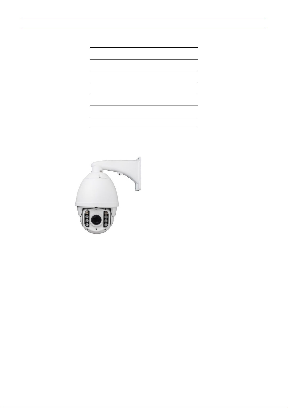
1080P 23X Network IR PTZ Camera
User manual
NOTE: This is a generic user manual for the IP PTZ camera,
as features and specifications vary. Please confirm the
features and specifications with the supplier.
Page 2

Contents
1 Introduction................................................................................................................................................................................................................................. 1
Performance Characteristics Features.............................................................................................................................................................................. 1
2 Hardware Installation.................................................................................................................................................................................................................2
System requirement..............................................................................................................................................................................................................2
Installation environment....................................................................................................................................................................................................... 2
Installation environment requirements.......................................................................................................................................................................2
Recommend operating environment.......................................................................................................................................................................... 2
Hardware installation steps..........................................................................................................................................................................................2
Network connection...................................................................................................................................................................................................... 3
Connection instruction.......................................................................................................................................................................................................... 4
3 Operating Guide for Network High Speed Dome..................................................................................................................................................................5
Set the IE Browser................................................................................................................................................................................................................ 5
Download and Install ActiveX..............................................................................................................................................................................................6
Login........................................................................................................................................................................................................................................8
Live view................................................................................................................................................................................................................................. 9
Playback............................................................................................................................................................................................................................... 11
File management................................................................................................................................................................................................................ 12
System specification setting..............................................................................................................................................................................................13
Device Information...................................................................................................................................................................................................... 13
QR code........................................................................................................................................................................................................................14
PTZ Settings................................................................................................................................................................................................................ 14
Time Settings............................................................................................................................................................................................................... 15
Audio Settings..............................................................................................................................................................................................................16
Display settings........................................................................................................................................................................................................... 17
Streams.........................................................................................................................................................................................................................18
ROI Settings.................................................................................................................................................................................................................19
Camera set...................................................................................................................................................................................................................19
Motion Detection......................................................................................................................................................................................................... 20
Video Tampering......................................................................................................................................................................................................... 21
Target Count................................................................................................................................................................................................................ 22
Object Left/Lost........................................................................................................................................................................................................... 23
Area Detection............................................................................................................................................................................................................. 24
Line Crossing...............................................................................................................................................................................................................25
Video Plan.................................................................................................................................................................................................................... 26
Network Settings......................................................................................................................................................................................................... 27
Http/Https......................................................................................................................................................................................................................28
Management Platform................................................................................................................................................................................................ 28
Multicast Config........................................................................................................................................................................................................... 29
DDNS Setting...............................................................................................................................................................................................................29
UPnP Settings............................................................................................................................................................................................................. 30
Email Settings..............................................................................................................................................................................................................31
Alarm Input................................................................................................................................................................................................................... 32
Alarm Output................................................................................................................................................................................................................33
Exception......................................................................................................................................................................................................................33
User Management...................................................................................................................................................................................................... 34
System Update............................................................................................................................................................................................................ 35
Auto Reboot................................................................................................................................................................................................................. 35
Storage Management................................................................................................................................................................................................. 36
Restore......................................................................................................................................................................................................................... 36
Local Setting................................................................................................................................................................................................................ 37
Developer..................................................................................................................................................................................................................... 38
Log.........................................................................................................................................................................................................................................38
Alarm.....................................................................................................................................................................................................................................39
4 Appendix................................................................................................................................................................................................................................... 40
SPECIFICATIONS.............................................................................................................................................................................................................. 40
Network Interface of Network High Speed Dome.......................................................................................................................................................... 42
Default Network Parameters............................................................................................................................................................................................. 42
Network High Speed Dome DDNS.......................................................................................................................................................................... 43
Page 3

DDNS description................................................................................................................................................................................................43
Network High Speed Dome DDNS analytical process..................................................................................................................................43
Visit Network High Speed Dome under different network environments................................................................................................................... 43
LAN................................................................................................................................................................................................................................43
Static IP.................................................................................................................................................................................................................43
Dynamic IP........................................................................................................................................................................................................... 44
Internet..........................................................................................................................................................................................................................44
Frequently asked questions.............................................................................................................................................................................................. 48
Page 4

CAUTION
Non-technician should not try to operate this high speed dome before reading this manual carefully. (This manual are subject to change
Cut the power supply off before operating the device to avoid damage caused by mal-operation.
Interior of the camera are precision optical and electrical instruments. Heavy pressure, shock and other incorrect operations should be
Please do not use the product under circumstances where the limits exceed the maximum specified temperature, humidity or power
Contents in this manual may be different from the edition that you are using. Should any unsolved problem occur given that the product
This manual content will be updated unscheduled, our company reserves the right to do manual contents update without further notice.
The default user name for this device is “admin”, and the password is“blank”(Users can set the password according to the reminder).
Device will enable preheat function when it is cold booting below -20 ℃, it will take about 30 minutes to warm up and get the device to
PTZ camera installation grounding lightning protection: ground resistance≤4Ω, ground wire (Olivine copper wire) sectional area ≥
without prior notice.)
prevented. Otherwise, may cause damage to product.
supply specifications.
is used according to this manual, please contact our technical support department or your product suppliers.
Default IP address is 192.168.1.188, HTTP port is 80, device port is 5050. Default communication protocol is pelcoD, baud rate is
115200 BIT/s, and PTZ address is No.1
start normal work.
1.2mm².
Page 5
PACKING LIST
Part
Quantity
Network IR PTZ Camera
1
Wall mounting bracket
1
Screws bag
1
CD
1
Check if the packing contents match the packing list on receiving the products. The packing list is as below.
Glove 2
Contact your local retailer if anything is missing in your package.
Page 6

1
1 Introduction
Performance Characteristics Features
Support max 1920*1080@30fps HD video output
H.264/H.265/MJPEG encoding
Low illumination 0.02Lux/F1.6(Color), 0.002Lux/F1.6(B/W), 0 Lux(IR on)
23X 2MP UHD optical zoom auto focus lens
Support 3DNR, WDR, defog, HLC, anti shake, etc
Support 360° pan endless; tilt 0°-90°
Support manual speed: 0.1°-180°/S, preset:200°/S
256 presets, 4 pattern scan, 8 preset cruise
3D positioning, privacy mask, PTZ watch
Support target counting, Object Left/Lost, area detection, line crossing detection
1CH audio input, 1CH audio output
2CH alarm input, 1CH alarm output, support alarm linkage
Support smart IR grouping control, IR distance can reach 120m
Support max 128G Micro SD card
SDK, ONVIF, API, GB/T28181 protocol
Lightning Protection, surging prevention, anti surge, IP66 protection level
Page 7
2
2 Hardware Installation
System requirement
LAN or WAN Internet to connect server, via PC Ethernet ( network card or network cable) TCP/IP protocol (Windows
Monitor and PC configuration:
Monitor: 17",1920×1080 resolution
Operation system: Windows NT, Windows2000, Windows XP or later.
Unpack the box to check the goods
Take out all goods which needed for installation from the box
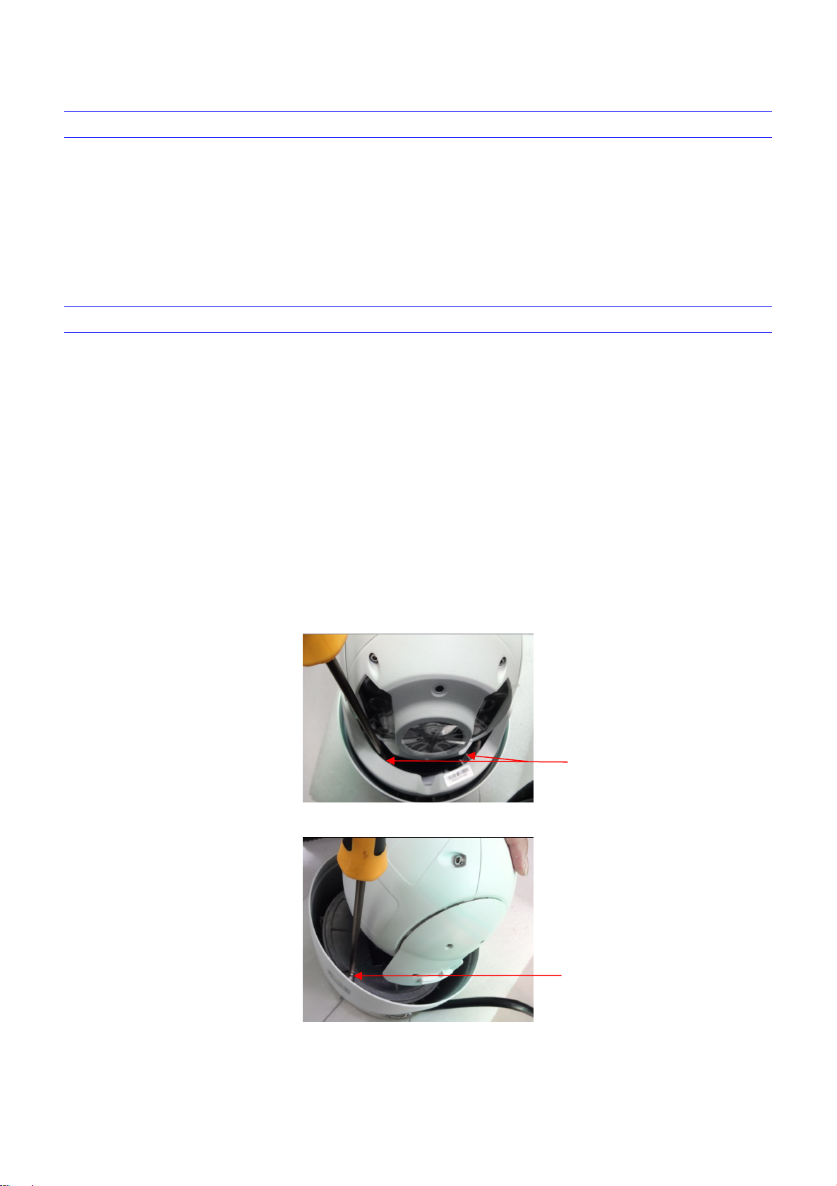
Take off the protection cover and insert the TF card. Please refer to the TF card installation steps below.
Remove the screws of
ornament(2pcs),then take
off ornament
Loosen the screws of
horizontal installation
panel(4pcs), then put up the
panel for a little
/NT/2000/XP) connect , suggest Internet Explorer 9.0 version or later.
CPU: PⅢ or latter, RAM: 512M or latter( Above DirectX8.1)
Installation environment
Installation environment requirements
Far away from humid or high-temperature environment; Choose proper place for ventilation; avoid installing on shaky place, and try to stay
away from heat device.
Recommend operating environment
-30°C~60°C
Hardware installation steps
Please make sure LAN and WAN are working in order before installation of the Network High Speed Dome. After checked all the network
system in good condition, keep your hands clean and dry, following the steps below.
Figure 2- 1
Figure 2- 2
Page 8
3
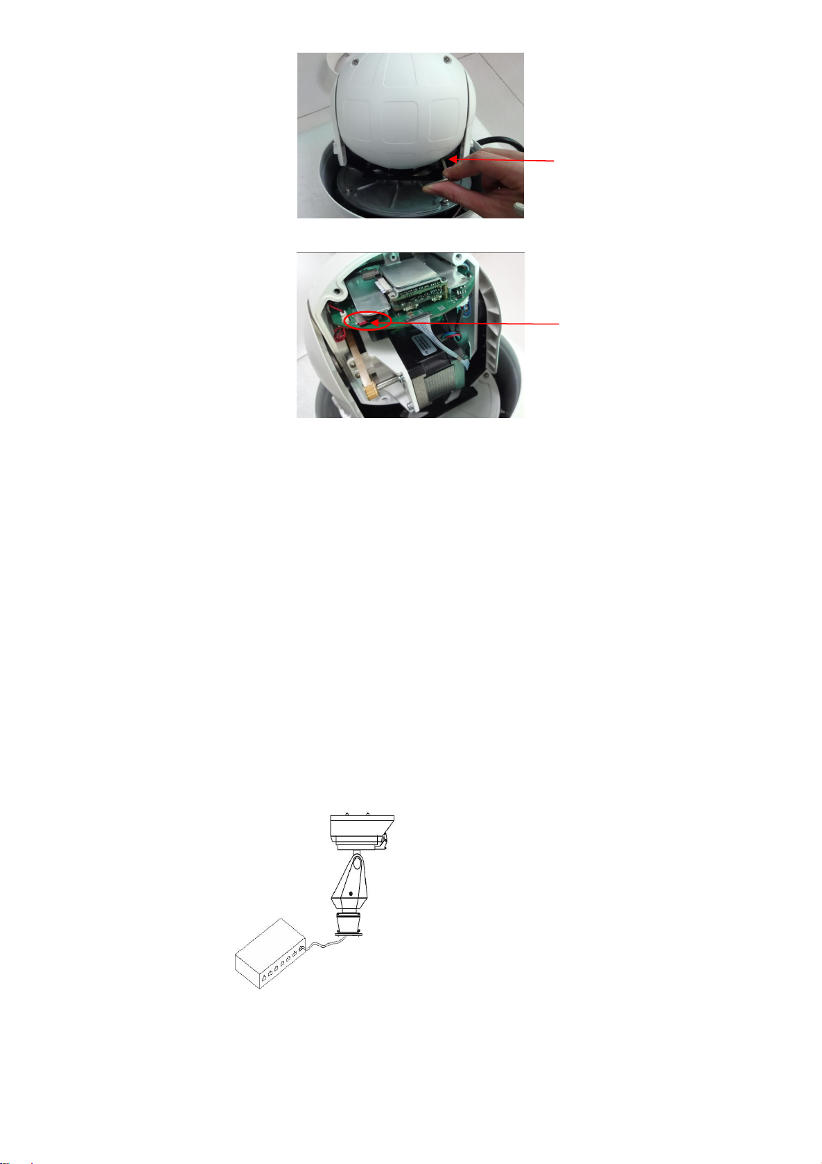
Figure 2- 3
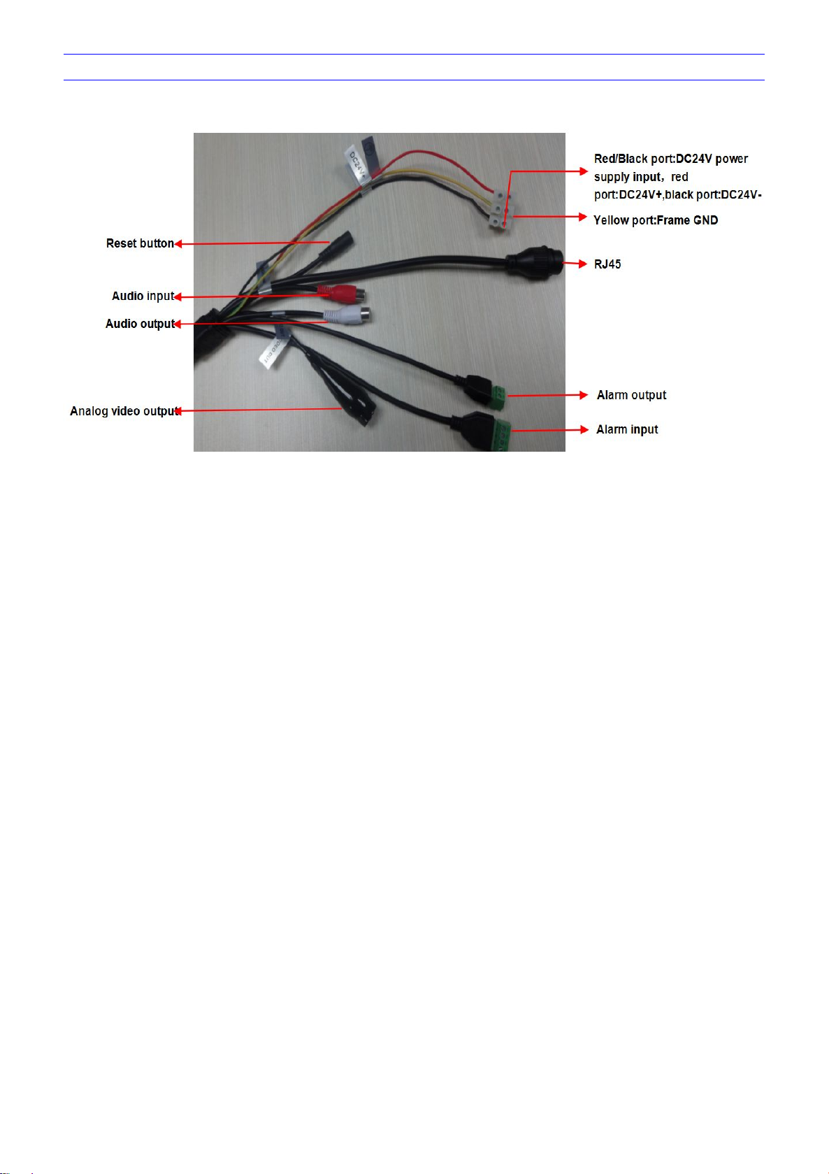
Connect related cables according to actual need (Power line, network line, audio line etc.)
Connect the power supply
When open the box, please check all of parts carefully, confirm the parts in the box as same as packing list.
Please read the user manual carefully before the installation.
Make sure to turn off all the power when install the camera
Please confirm the power transformer, avoid the device damage with unmatched power source
LAN connection
WAN connection
Connect the power supply
Loosen the screws of back
cover(4pcs),and take off
the cover
Insert TF card
Figure 2- 4
Please read the Note carefully, any question you should contrast us without hesitation.
Note:
Network connection
Use one network line to connect IP camera with concentrator or switchboard of the LAN. As shown below, you can also use one
network line to directly connect Network High Speed Dome with your network card or switchboard
Use one network line to connect Network High Speed Dome with Router or XDSL Modem/Cable Modem. as shown bellow.
After connect the power source, the network camera will start operation automatically.
Page 9
4
Connection instruction
Page 10
5
3 Operating Guide for Network High Speed Dome
Set the IE Browser
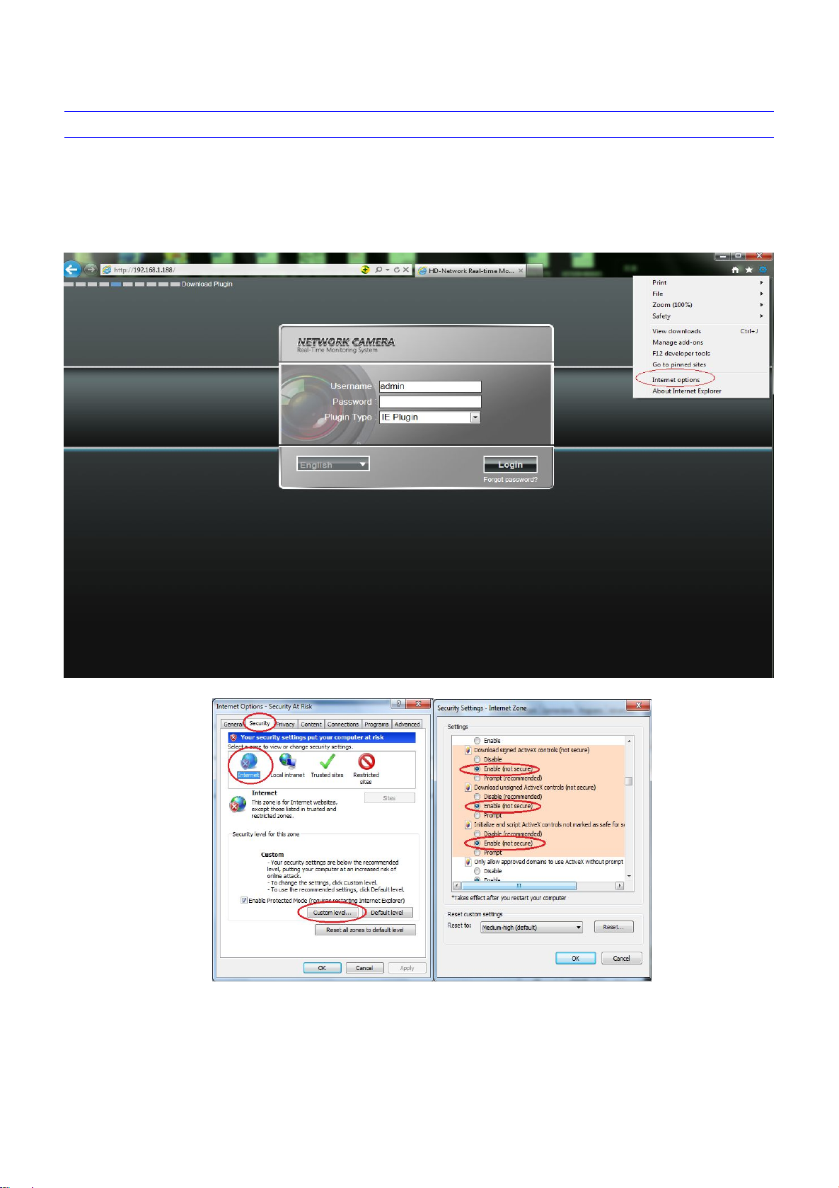
Due to the high level of IE security settings, the downloading of ActiveX and the updating of software will be influenced, probably failed to
conduct that. To realize the function of visiting the network PTZ camera video, it need to set the IE browser previously.
Setting Method: Open the IE browser, click “Internet Options” into the "tools/Internet Options/Security/Custom Level" page, click the
"Custom Level", and then “Start Using” the “ActiveX and plugins”. You can choose the recommended choice if it’s unsafe to start using, as
shown in the figure below:
Page 11

6
Download and Install ActiveX
You need to install ActiveX Control when you visit Network High Speed Dome for the first time through IE browser.ActiveX installing
method:
Download installation
Input the IP address of Network High Speed Dome(default address http://192.168.1.188.) in Internet Explorer to enter into login page,
Click to download and install Active X, it will pop-up installation control message after clicking, Click "run", install the ActiveX according to the
prompt.as shown in the following figure:
Figure 3- 1
A file download dialog will pop out, click “Next” to installation. as shown in the follow figure 3-2
Figure 3- 2
Select the ActiveX installation and storage file, the default installation and storage file is c:\Program Files\webactivex-rtsp, and click
“Next” to enter next dialog. as shown in the follow figure 3-3
Page 12

7
Figure 3-3
Click “ Install” to enter into the next dialog. as shown in the follow figure 3-4
Figure 3-4
Click “Finish” to complete the ActiveX installation. as shown in the follow figure 3-5
Figure 3-5
Page 13
8
Login
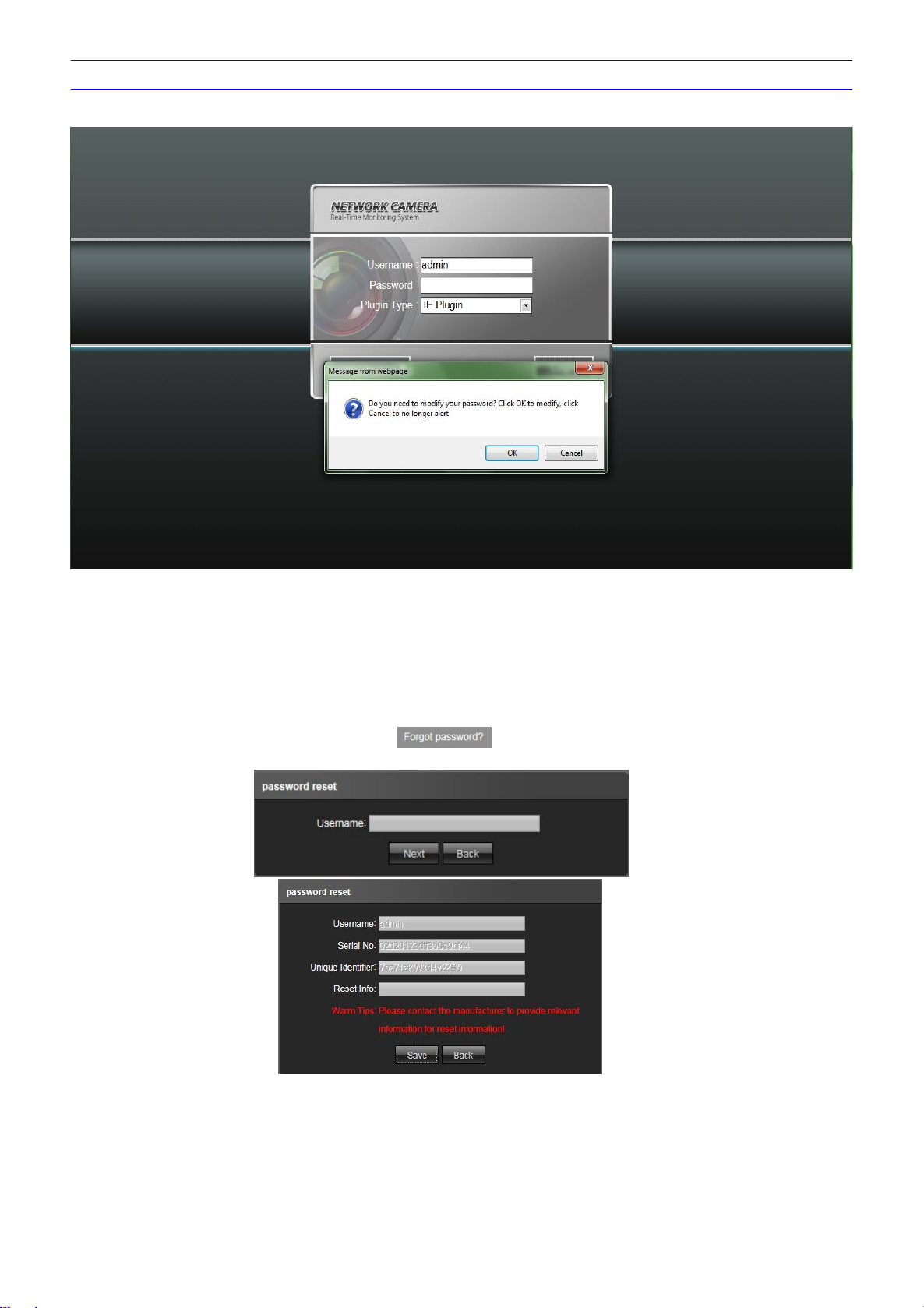
After installing the Active X, click “Login” will prompt whether to change the password, as shown in the following figure:
Figure 3-6
User Name: admin (default setting)
Password: blank (default setting) (Users can set the password according to the reminder)
Plugin Type: IE Plugin or Flash Plugin. If you use IE browser, then please select IE Plugin to login. While you use other browsers,
then select Flash Plugin to login. (Note: Select Flash Plugin without installing Activex control)
Select Language: English, implified Chinese, traditional Chinese
Note: if user sets password and then forgets, click on below the "login" , will pop-up password reset window (user
name default admin) ,can return password to factory settings according to the prompt .
Page 14
9
Live view
Voice intercom: Connect sound pick-up device on the audio input port and active loud speaker on the audio output port, then click
Capture: click button, snap the current image and save it in .JPG format automatically to the storage directory of snapped
Full Screen: press button or click right mouse button to live preview in full screen, press the Esc key or remove clip to exit full
Record: ON/ OFF selectable. When select ON, the icon turn blue as ., and device do video recording and saved in the
Event Type: Warns light flashing when camera device inform alarm. Support kinds of alarms record, and setup or remove the
Zoom-in: Use the mouse to do local zoom for the video display area by scrolling the mouse wheel.
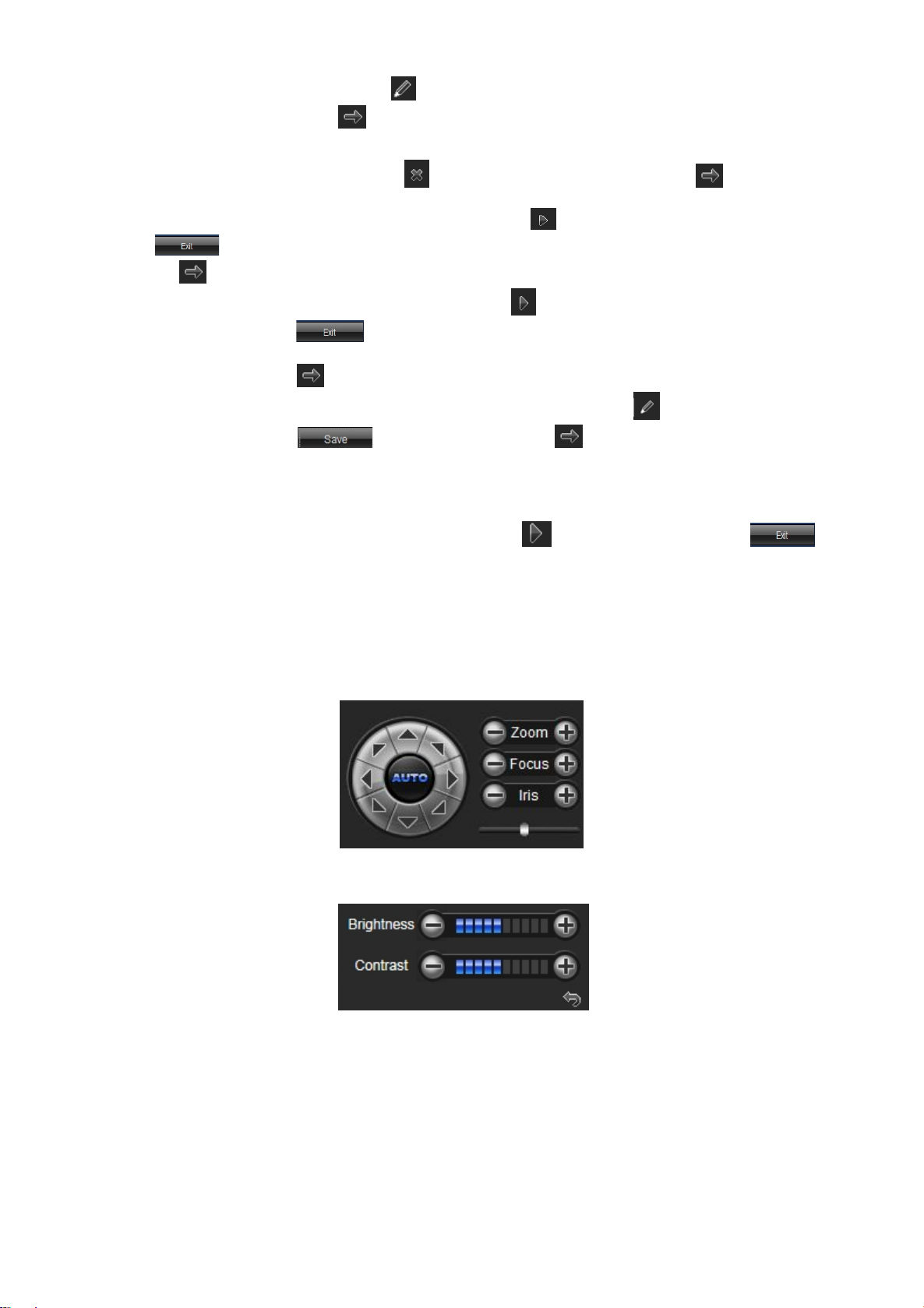
PTZ control: Up/ down/ left/ right/ auto/ adjust the PTZ rotate speed, etc. as shown in the follow figure 3-8.
Lens control: Do scaling, focus, iris operation, as shown in the follow figure 3-8.
Brightness: The brightness of graphics can be adjusted,but it can only change the brightness what the current previewed graphics
Contrast: The contrast ratio of graphics can be adjusted,but it can only change contrast ratio of what the current previewed
Cyclotron arrow: Restore the default parameters of brightness and contrast. as shown in the follow figure 3-9.
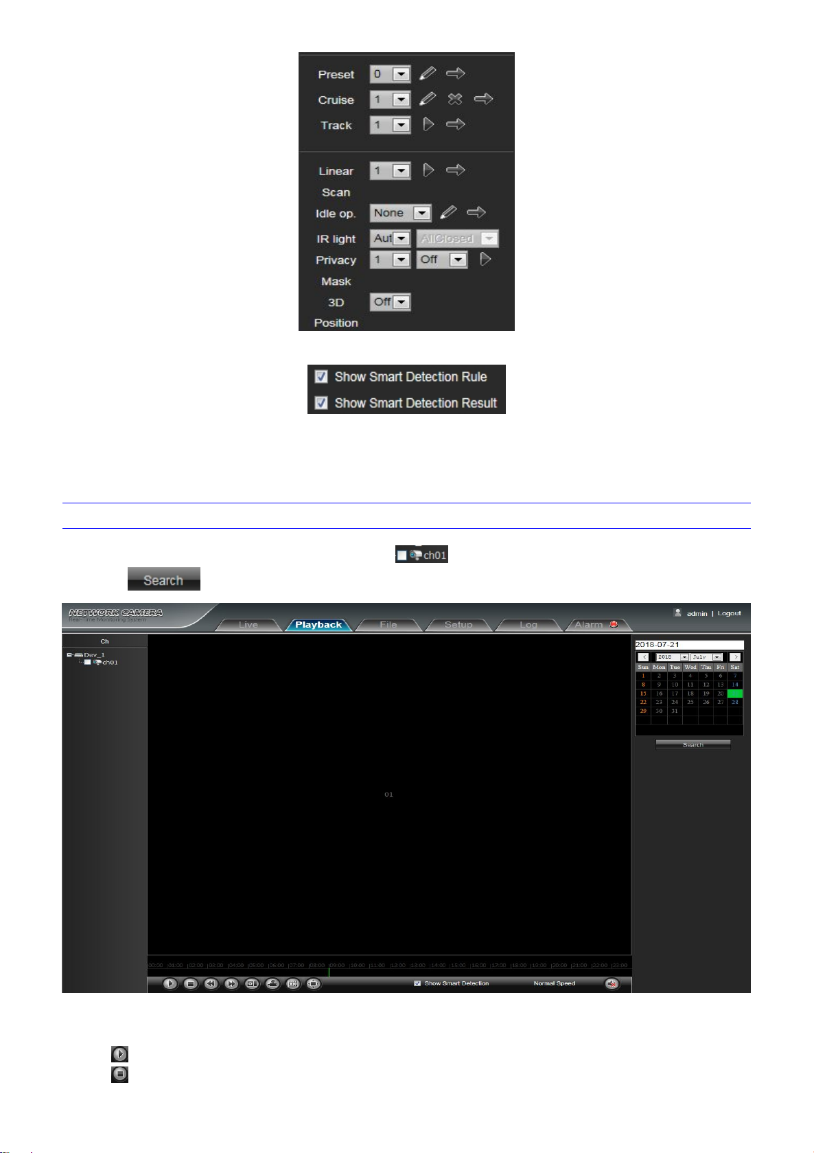
PTZ setting: preset setting, cruise, track setting, linear scan, idle ope , IR light, Privacy Mask, 3D Position, as shown in the follow
Note: The inserted TF card is for full function display interface, otherwise, it's for simple type interface.
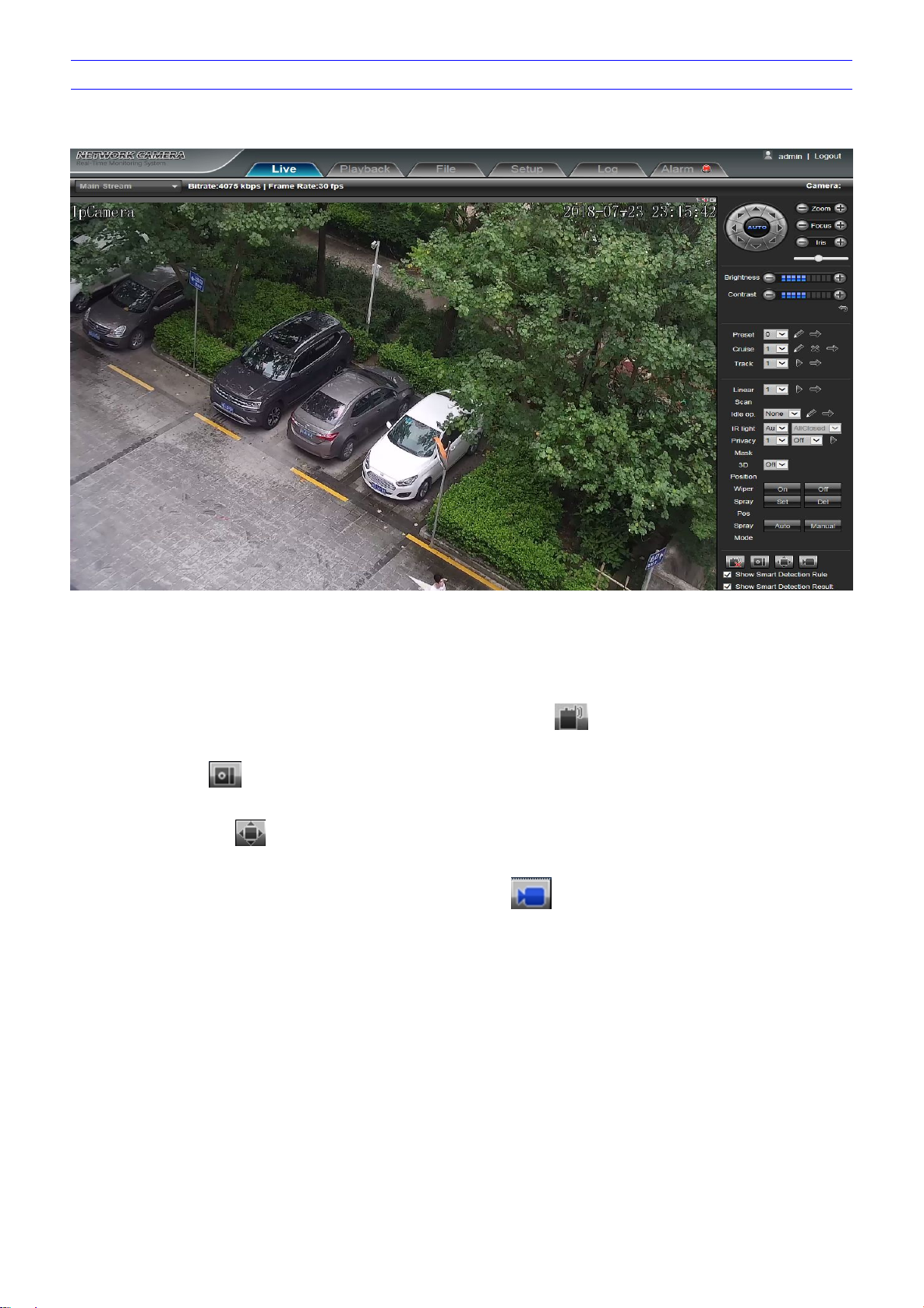
Live preview interface as shown in the follow figure:
Figure 3- 7
In the Live view interface, users can do operations such as voice intercom, listen, capture, full-screen preview, video record, Event Type
check, PTZ and lens control, brightness, contrast, preset setting, cruise, track setting, linear scan, idle op., IR light, Privacy Mask, 3D
Position,etc.
the talkback icon. Turn on the voice intercom switch and the icon shows as , the talkback between PC and Network High
Speed Dome can be performed. Audio input setting as default mode.
images. The default path is C:\Program Files\PREVIEW, and the storage path is changeable.
screen
appointed files as AVI format
alarm setting,clear the alarm information.
displayed, and it won't be effective in the video,as shown as in the figure 3-9.
graphics displayed, and it won't be effective in the video,as shown as in the figure 3-9.
figure 3-10.
Page 15
10
Preset setting: Adjust the camera to the appointed angle and location through directional buttons, and then select a preset
Show smart detection rule: choose whether to display intelligent detection types (total four types: Target Count, Object Left/Lost,
Show smart detection result:choose whether to display intelligent detection statistical result.
number on the preset drop down list, click to set it. Call preset: Select a preset number which needed to call on the
preset drop down list, then click to call it.
Cruise: 0-255 presets addable, stay time 1-255s adjustable, cruise speed 1-7 levels selectable. All cruise tracking can be call
and delete independently.Clear cruise: Click to clear all cruise scan setting, Call cruise: Click to call the cruise scan
which has been set
Track setting: Select a number at the tracking drop down list, click , and do a serious PTZ operation, then click
to save and exit the tracking path setting. Call tracking path: Select a number at the tracking drop down list,
click to call tracking path
Linear Scan: Select a number at the linear drop down list, click to set the linear scan initial position, and do a serious
PTZ operation, then click to save and exit the linear scan setting. Linear scan only supported horizontal scan, and
the vertical angle depend on the final position, linear path is two point minimum path. Call linear: Select a number at the
linear drop down list, click to call linear scan
Idle op. : Idle op. include None, preset setting, cruise scan, tracking, linear scan. Click to set idle ope, and the idle time is
1-15 min selectable, click to save the idle op. setting, click to verify whether the idle ope setting completed.
When set idle ope successfully, speed dome camera will do idle ope operation after the idle time that has been set
IR light: Auto/ Manual selectable, when select Auto, it will turn on the IR led according to the zoom module multiples. When
select Manual, there All close/ near open/ middle open/ far open totally four kind of choices
Privacy Mask: Select a number at the Mask drop down list, click to set the masking area, then click to
save and exit the masking setting
3D Position: 3D position function can be opened or closed
Area Detection, Line Crossing).
Figure 3- 8
Figure 3-9
Page 16
11
Figure 3- 10
Start: Start the current playback
Stop: Stop the current playback
Figure 3- 11
Playback
Playback interface as shown in the follow figure.Click the icon , next select the date time of the calling video in need, then
click the icon , the record video will search automatically.
Figure 3- 12
Page 17
12
Slow: Slow down the playback speed(1/2, 1/4, 1/8, 1/16 times optional)
Fast: Speed up the playback speed(2, 4, 8, 16 times optional)
Snapshot: Can be snapshot in playback channel
Backup: Can be backup video in playback channel
Frame Play: Single frame to play
Full Screen: Playback video will display with full screen
Show smart detection: when the video is to intelligent detect video,it can display intelligent Detection rules and statistical result.
Voice: Adjust the volume of playback audio
(Note: device should support TF card storage to enable this function)
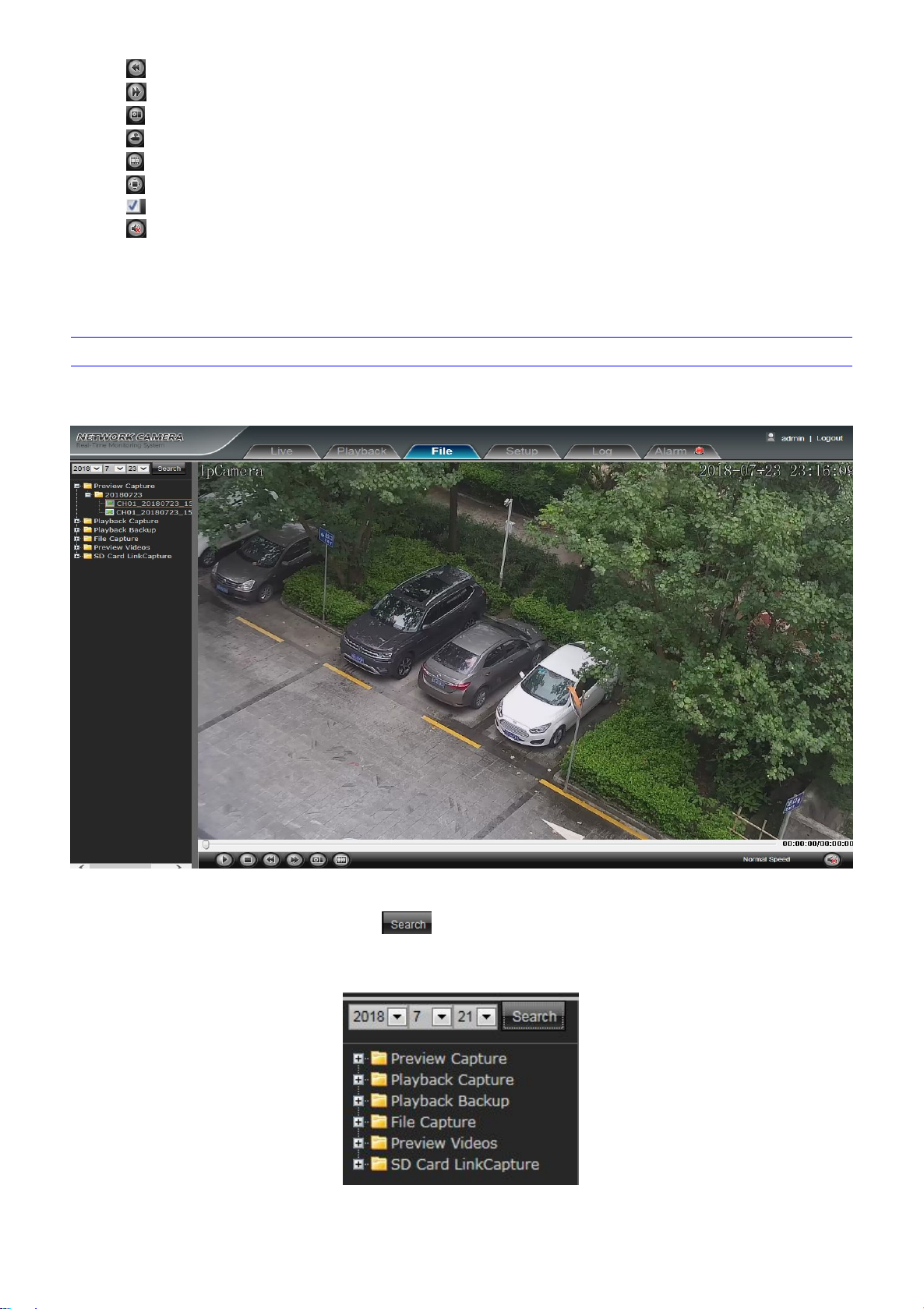
Search: Input the concrete time, and click the button, the lower part displays searched images and videos (double click to
Preview Capture: To review video record preview capture files, search and double click the image files directly
Playback Capture: To review video record playback capture files, search and double click the image files directly.
File management
Network High Speed Dome“File management” setting interface as shown in the follow figure.
Note: The inserted TF card is for full function display interface, otherwise, it's for simple type interface.
Figure 3-13
display files)
Page 18

13
Playback Backup: To review playback video files, search and double click the video files directly.
File Capture: To review capture files in file management, search and double click the image files directly.
Preview Videos: To review preview interface video record files, search and double click the video files directly.
SD Card Link Capture:To review SD Card Link Capture files, search and double click the video files directly.
Backup Video Play:
Start: Click button to play the backup video image file
Stop: Click button to stop the the play
Slow: Click button to slow play the backup video image file
Fast: Click button to fast play the backup video image file
Frame: Click button to play the backup video image file by frame
Capture: Click button to snap the backup video image during display
Voice: Click button to select turn on/off the voice during backup video image display
System specification setting
Device Name: Edit the camera name
Device Type: Display the device type
Serial No. : Display the product serial No.
Firmware Version: Display the software version date(Note: Based on the version information which displayed in factory product)
Hardware Version: Display the hardware version number
Format: Switch to select the PAL and NTSC image scanning system
Note: The inserted TF card is for full function display interface, otherwise, it's for simple type interface.
Device Information
Network High Speed Dome“Device Information” interface as shown in the follow figure:
Figure 3- 14
After all parameters setting completed, click “Save” and then it comes into effect immediately.
Page 19

14
QR code
The display interface of QR code of IP Camera is shown as below, iphone users use the "RichScan" browser to scan IOS APP QR code
to turn to Fseye downloading interface, Android mobile users use the "RichScan" of browser to scan the Android APP QR code to turn to
Fseye downloading interface.Use Fseye mobile client can directly scan the Device ID QR code to login.
(Note: The Device ID QR icon will display only after the opening the corresponding agreement in platform management interface,and it
supports QR code at present: Fseye, Fseye is corresponding to Fseye client in platform management interface)
Figure 3- 15
PTZ Settings
Network High Speed Dome“PTZ Settings” interface as shown in the follow figure.
Figure 3-16
Page 20

15
Protocol: Support pelcoD and pelcoP protocol
Address: 1-255 adjustable, default is 1
Baud Rate: Baud rate 115200 supported only
After all parameters setting completed, click “Save” and then it comes into effect immediately.
Device Time: Set and display the device current time
Time Zoom: Different area time format selectable
GMT: Adjust the time more exact
NTP Enable: Click to determine whether to use NTP
Server Address: Input NTP server IP address
Interval: Input the interval time
Enable DST: Can choose to enable or close the DST function, If in the implementation of daylight saving time region, just click
From: Set begin DST time
To: Set end DST time
DST Bias: Set DST offset time
Time Settings
Network High Speed Dome “Time Settings” interface as shown in the follow figure.
Figure 3-17
the enable daylight saving time
After all parameters setting completed, click “Save” and then it comes into effect immediately.
Page 21

16
Audio Settings
Audio Source: Select the audio input mode, LineIn or MicIn selectable
Input Volume: Set the size of the input volume,the range of volume:0-100, default is 50
Output Volume: Set the size of the output volume,the range of volume:0-100, default is 50
Network High Speed Dome“Audio Settings” interface as shown in the follow figure.
Figure 3-18
After all parameters setting completed, click “Save” and then it comes into effect immediately.
Page 22

17
Display settings
Name:Modify the appointed channel name
Main Stream OSD: Modify the appointed channel font of main stream OSD
Sub Stream OSD: Modify the appointed channel font of sub stream OSD
Third Stream OSD: Modify the appointed channel font of Third stream OSD
Multi OSD:Add multi user-defined OSD, it can be selected Show or not
Time Format: Select different time display mode for the appointed channel
Date Format: Select different date display mode for the appointed channel
Bright: Adjust the brightness for the appointed channel
Contrast: Adjust the contrast for the appointed channel
Saturation: Adjust the saturation for the appointed channel
Hue: Adjust the hue for the appointed channel
Cyclotron Arrow: Restore the default parameters(Only for Bright, Contrast, Saturation and Hue)
Name: Set the channel title location for the appointed channel
Date Time: Set the channel date location for the appointed channel
Multi OSD: Multi-line OSD characters can be set up the corresponding location
OSD Color: Can set the color of the OSD font
OSD Font:Optional OSD font
Network High Speed Dome“Display settings” interface as shown in the follow figure.
Figure 3-19
After all parameters setting completed, click “Save” and then it comes into effect immediately.
Page 23

18
Streams
Compress type: Primary Stream(Normal)/ Sub Stream/Third Stream selectable
Stream: Including complex stream/ video stream two types
Resolution: The camera supports several resolution, will display here
Frame Rate: Select different frame rate in the drop-down list, default is Full Frame
Video Encode: H.264/H.265/MJPEG three kinds of video encode format
H264 Profile: There are MainProfile/ Baseline/ HighProfile three types optional
I frame Interval: Set the I frame interval size
Bitrate Type: Constant/ Variable selectable
Bitrate: Set different bitrate for different channels
Network High Speed Dome“Streams” setting interface as shown in the follow figure.
Figure 3-20
After all parameters setting completed, click “Save” and then it comes into effect immediately.
Page 24

19
ROI Settings
ROI Setting: On the preview window, hold down the left mouse button and drag to set the ROI area. A total of four ROI areas can
IP Camera ROI Settings setting interface as shown in the follow figure:
Figure 3-21
be set, click to set the corresponding ROI region coding level, the higher the level of coding, the stronger the ROI
region encoding
After all parameters setting completed, click “Save” and then it comes into effect immediately.
Camera set
Network High Speed Dome“Camera set” setting interface as shown in the follow figure.
Page 25

20
Figure 3-22
Exposure Mode: Exposure mode include Full-automatic/ Shutter Priority/ Anti-Flicker, default is Full-automatic. When select Full-
AGC: Low/ Mid/ High selectable, default is High. The bigger of the gain value, the higher of the low illumination sensitivity, and the
Shutter:1/5~1/10000, the smaller of the shutter value, the darker of the brightness
Color-Mode: Normal/ Bright/ Nature selectable, default is Normal
WB Mode: Auto WB/ Inside/ Outside selectable, select different white balance mode according to different scenes, default is Auto
Mirror: Normal/ Horizontal Mirror/ Vertical Mirror/ 180 rotation selectable, default is Normal
Backlight Mode: Off/ WDR/Highlight Correction/Backlight correction selectable, default is Off
Intensity: Low/ Mid/ High selectable. It is invalid when Backlight mode set Off
Dark Compensation: Off/On selectable, default is Off
DNR Mode: Off/ Low/ Mid/High selectable, default is Mid
Zoom Rate: Show/ Hide selectable, set the zoom rate and view the corresponding effect on the screen interface
Coordinate: Show/ Hide selectable, set the zoom rate and view the corresponding effect on the screen interface
Status: Show/ Hide selectable, set the zoom rate and view the corresponding effect on the screen interface
Zoom Speed: Low/ Mid/ High selectable, default is High
Anti-Shake:Off On selectable, default is Off
Slow Shutter: Off/ On selectable, default is Off
Defogging:Off/ On selectable, default is Off
Day-Night Mode: Auto/ Color/ Black White three kinds of mode selectable,default is Auto, According to the actual scene to select
Enable: Select whether open the motion detection function.
Sensitivity: The higher of the sensitivity, the obvious of the motion detective.
Week:The protection time can be set up from Monday to Sunday.
Arming Schedule: Can set up protection period of time, one day can set up 8 time quantum.
Area Setting: Press and drag the left mouse button in the Area Setting preview interface, then draw the small check optional to set
Clear: Click Clear to clear the current detective areas.
Email: Send Email to appointed mailbox when alarm triggered.
automatic or Anti-Flicker, the shuttle value can not be set, and when select Shutter Priority, the shuttle value can be set.
more obvious of noisy point
WB
the Day&Night mode
After all parameters setting completed, click “Save” and then it comes into effect immediately.
Motion Detection
Network High Speed Dome“Motion Detection” setting interface as shown in the follow figure.
Figure 3-23
the detective areas
Page 26

21
Snap: Click Snap. Once alarm triggers that it will linkage camera to snapshot picture and store it in the TF card.
Record: Click Record.Once alarm triggers that it will linkage camera to record video and restore it in the TF card.
Alarm Output: There is a warner connect the alarm output port, alarm triggered the embedded relay switch to make alarm output.
PTZ: Enable or disable PTZ function
Preset: When motion detection triggers alarm, it will linkage the presets
Snap Interval: Set the snapshot interval time
Snap Number: Set the snapshot image count for every time
After all parameters setting completed, click “Save” and then it comes into effect immediately.
Enable: Set whether open the video tempering
Sensitivity: The higher the sensitivity, the more easier to trigger the video block alarm
Week:The protection time can be set up from Monday to Sunday.
Arming Schedule: Can set up protection period of time, one day can set up 8 time quantum.
Area Setting: Press and drag the left mouse button in the Mask Set preview interface, then draw the small check optional to set the
Clear: Click Clear to clear the current detective areas.
Email: Send Email to appointed mailbox when alarm triggered.
Snap: Click Snap. Once alarm triggers that it will linkage camera to snapshot picture and store it in the TF card.
Record: Click Record.Once alarm triggers that it will linkage camera to record video and restore it in the TF card.
Alarm Output: There is a warner connect the alarm output port, alarm triggered the embedded relay switch to make alarm output.
PTZ: Enable or disable PTZ function
Preset: When motion detection triggers alarm, it will linkage the presets
Snap Interval: Set the snapshot interval time
Snap Number: Set the snapshot image count for every time
Video Tampering
Network High Speed Dome“Video Tampering” setting interface as shown in the follow figure.
Figure 3-24
detective areas
After all parameters setting completed, click “Save” and then it comes into effect immediately.
Page 27

22
Target Count
Enable: Enable or disable the target counting function
Arming Schedule: Arm schedule can be set from Monday to Sunday
Area Setting: In preview interface of “Area Setting”, click “drawing”, then click the left mouse button to set detection line, then right-
Clear: Click Clear to delete all the test lines
Swap AB: Click "swap AB" to exchange position between A and B.
Test Line: To add new test lines (support max. 4 test lines), or set the parameter setting for the corresponding test line optional
Statistics: Set the test lines for targets passing through, there are A→B and B→A two statistical methods.
Flow Counter: Enable or disable the Flow Counter function
Interval: Set the counting time interval, when it is more than the time interval, the flow counter will reset and enter into next
Threshold: Set the upper limit value for counting, when it is more than the setting value, it will trigger alarm function automatically
Total Counter: Enable or disable the Total Counter function
Time: Set the effective time period for the day’s total counter
Alarm Threshold: Set the upper limit value for the day’s total flow, when it is more than the setting value, it will trigger alarm
Target Percent: Set the min. area percent for the effective counting targets, once the area of targets passing through the test line
Email: Click Email. Once alarm triggers that it will send Email to appointed mailbox
Snap: Click Snap. Once alarm triggers that it will linkage camera to snapshot picture and store it in the TF card
Record: Click Record. Once alarm triggers that it will linkage camera to record video and store it in the TF card.
Alarm Output: There is a active warner connected to the alarm output port. Once alarm triggers that it will linkage embedded relay
PTZ: Enable or disable PTZ function
Preset: When target counting triggers alarm, it will linkage the presets
Snap Interval: Set the snapshot interval time
Snap Number: Set the snapshot image count for every time
Network High Speed Dome Target Count setting interface as shown in the follow figure.
Figure 3-25
click to complete, the target will be counted when going through the line.
counting period automatically
function automatically
are smaller than the setting value, it will be invalid without be counted
switch to make alarm output
After all parameters setting completed, click “Save” and then it comes into effect immediately.
Page 28

23
Object Left/Lost
Enable: Enable or disable the object detection function
Arming Schedule: Can be set the arm schedule from Monday to Sunday
Area Setting: In preview interface of "Area Setting" , click "drawing", then click the left mouse button to set detection area, then
Clear: Click Clear to delete all the detect zones.
Detect Area: To add new detect zone (support max. 4 detect zones), can be set the parameter setting for the corresponding detect
Detect Type: Set the object detection type, there are three detection types, both of them will trigger alarm. Item lost refers to once
Object Percent: Set the min. area percent for the object, the area of object is smaller than the setting value, it will be invalid
Time: Set the upper limit value for the item lost and item left, when it is more than the setting value, it will trigger alarm function
Email: Click Email. Once alarm triggers that it will send Email to appointed mailbox
Snap: Click Snap. Once alarm triggers that it will linkage camera to snapshot picture and store it in the TF card
Record: Click Record. Once alarm triggers that it will linkage camera to record video and store it in the TF card.
Alarm Output: There is a active warner connected to the alarm output port. Once alarm triggers that it will linkage embedded relay
PTZ: Enable or disable PTZ function
Preset: When object detection triggers alarm, it will linkage the presets
Snap Interval: Set the snapshot interval time
Snap Number: Set the snapshot image count for every time
Network High Speed Dome Object Left/Lost setting interface as shown in the follow figure.
Figure 3-26
right-click to complete, items in the area will be monitored and detected
zone optional
the object lost in the detect zone, the camera will trigger alarm, Item left refers to once the new added object detected in the
detect zone, the camera will trigger alarm.Item lost or left refers to both of object lost and adding,the camera will trigger alarm.
automatically
switch to make alarm output
After all parameters setting completed, click “Save” and then it comes into effect immediately.
Page 29

24
Area Detection
Enable: Enable or disable the area detection function
Arming Schedule: Can be set the arm schedule from Monday to Sunday
Area Setting: In preview interface of "Area Setting" , click "drawing", then click the left mouse button to set detection area, then
Clear: Click Clear to delete all the detect zones.
Detect Area: To add new detect zone (support max 4 detect zones), can be set the parameter setting for the corresponding detect
Detect Type: Set the target detect type, there are four detect types, all of them will trigger alarm. Target enter refers to once the
Object Percent: Set the min. area percent for the object, the area of object is smaller than the setting value, it will be invalid
Time: When the staying time of the set target entering into detection area exceeds the upper limit of setting time, it will trigger the
Email: Click Email. Once alarm triggers that it will send email to appointed mailbox
Snap: Click Snap. Once alarm triggers that it will linkage camera to snapshot picture and store it in the TF card
Record: Click Record. Once alarm triggers that it will linkage camera to record video and store it in the TF card.
Alarm Output: There is a active warner connected to the alarm output port. Once alarm triggers that it will linkage embedded relay
PTZ: Enable or disable PTZ function
Preset: When area detection triggers alarm, it will linkage the presets
Snap Interval: Set the snapshot interval time
Snap Number: Set the snapshot image count for every time
Network High Speed Dome Area Detection setting interface as shown in the follow figure.
Figure 3-27
right-click to complete, items in the area will be monitored and detected
zone optional
target enter into the detect zone, the camera will trigger alarm, Target leave refers to the target go out the detect zone, the
camera will trigger alarm, Target enter or leave refers to both of them happen, the camera will trigger alarm .When the staying
time of target wander target entering into detection area exceeds the upper limit of setting time, it will trigger the alarm
alarm
switch to make alarm output
After all parameters setting completed, click “Save” and then it comes into effect immediately.
Page 30

25
Line Crossing
Enable: Enable or disable the virtual guard function
Arming Schedule: Can be set the arm schedule from Monday to Sunday
Area Setting: In preview interface of "Area Setting" , click "drawing", then click the left mouse button to set warning line, then right-
Clear: Click Clear to delete all the detect zones.
Swap AB: Click "swap AB" to exchange position between A and B
Detect Area: To add new guard line (support max. 4 guard lines), can be set the parameter setting for the corresponding guard
Detect Type: Set the guard lines to trigger alarm. A→B refers to the targets pass through the guard line from A area to B area and
Object Percent: Set the min. area percent for the object, the area of target passing through the guard line is smaller than the
Email: Click Email. Once alarm triggers that it will send Email to appointed mailbox
Snap: Click Snap. Once alarm triggers that it will linkage camera to snapshot picture and store it in the TF card
Record: Click Record. Once alarm triggers that it will linkage camera to record video and store it in the TF card.
Alarm Output: There is a active warner connected to the alarm output port. Once alarm triggers that it will linkage embedded relay
PTZ: Enable or disable PTZ function
Preset: When virtual guard triggers alarm, it will linkage the presets
Snap Interval: Set the snapshot interval time
Snap Number: Set the snapshot image count for every time
Network High Speed Dome Line Crossing setting interface as shown in the follow figure.
Figure 3-28
click to co mplete, the target will trigger the alarm when going through the line
lines optional
trigger alarm. A←→B refers to the targets pass through the guard line from A area to B area or from B area to A area, both of
them will trigger alarm.
setting value, it will be invalid without triggering alarm
switch to make alarm output
After all parameters setting completed, click “Save” and then it comes into effect immediately.
Page 31

26
Video Plan
Video Mode: Select the video mode, there are Time recording + Alarm recording, Time recording , Alarm recording, No video four
Week: You can set the recording time from Monday to Sunday
Pre Record: Pre-recording time can be set
Post Record: You can set the recording delay time
Video Edge IP Address:enter the IP of NVR or server
IP Camera Video Plan setting interface as shown in the follow figure:
Figure 3-29
modes optional
After complete all parameters setting, click Save, the settings will take effect immediately.
Page 32

27
Network Settings
IPV4: IP protocol version No. is 4
Static IP: The device IP address is permanent
DHCP: Click DHCP, when turn on the router’s DHCP, the camera will get the IP address from router automatically
IP address: Input the corresponding numbers to change the IP address
Subnet Mask: Input the corresponding IP subnet mask
Default Gateway: Input the corresponding gateway address
DNS 1: DNS server address
DNS 2: DNS server standby address
RTSP Port: Use domain name to access and login device need mapping RTSP, default port is 554
RTSP Validation: Choose RTSP verification mode, Http-Base64, Http-Digest selectable. After clicking to check and enable the
RTMP Port: Use domain name to access and login device need mapping RTMP, default port is 1935
Enable PPPoe: Click to enable PPPOE
Network High Speed Dome“Network Settings” interface as shown in the follow figure.
Figure 3-30
corresponding RTSP verification mode, When playing RTSP real-time stream, it needs to verify the user name and password
User Name: Input the user name
Password: Input the password
Confirm pwd: Input the password again to confirm it
PPPoe IP: Input device dynamic address
After all parameters setting completed, click “Save” and then it comes into effect immediately.
Page 33

28
Http/Https
Enable: Select whether to enable the http/https
HTTP Port: Input the corresponding port ( Default is 80)
HTTPS Port: Input the corresponding port ( Default is 443)
Network High Speed Dome“Http/Https” interface as shown in the follow figure.
Figure 3-31
After all parameters setting completed, click “Save” and then it comes into effect immediately.
Management Platform
Network High Speed Dome “Management Platform” interface as shown in the follow figure.
Figure 3-32
Page 34

29
User can open,close,edit,delete the protocol.
Multicast Config
Network High Speed Dome“Multicast Config”setting interface as shown in the follow figure.
Figure 3-33
Default disabling for multicast config. After click"Enable Multicast", users can set the primary stream video,primary stream audio, sub
stream video, sub stream audio, third stream video, third stream audio.
DDNS Setting
DDNS is implemented through a dynamic domain resolution server. It requires a PC with fixed IP address on the Internet, on which
the dynamic domain resolution server runs. Network High Speed Dome DDNS setting interface as below:
Page 35

30
Figure 3-34
Enable DDNS: Click to determine whether to use Dynamic Domain Name Server
Server Type: Select DDNS server type (There are Dyndns/ PeanutHull/ NO-IP/ 3322/ DnsDynamic five types selectable)
Status:Select on or off
Server Address: Input server name, for example, members.3322.org
Port: Input port No.(default is 80)
User Name: Input user name
Password: Input password
Confirm Pwd: Input the password again to confirm it
Domain: Input the standby domain
Enable UPnP: you can choose whether to turn on the UPnP function. When enabled, the device can port mapping through the
Add: optional TCP/UDP protocol, set internal and external port。
After all parameters setting completed, click “Save” and then it comes into effect immediately.
UPnP Settings
Network High Speed Dome“UPnP Settings” interface as shown in the follow figure.
Figure 3-35
router.
Page 36

31
Email Settings
Sender's Address: Input the address of the outbox
Password: Input the the password of the outbox
Confirm pwd: Input the password again to confirm it
SMTP Server: Input the smtp server address of the outbox
SMTP Port: Input the smtp server port of the outbox
SSL/Identity verification:Tick and to send the email correctly and safely
Receiver's Address: Input the address of the inbox, fill in the address of receiving email,and can fill in 3 address of receiving email
Network High Speed Dome“Email Settings” interface as shown in the follow figure.
Figure 3-36
After all parameters setting completed, click “Save” and then it comes into effect immediately.
Page 37

32
Alarm Input
Alarm Input: Select the alarm input number, Then click can implement follow parameters settings
Alarm In Name: Input alarm input name
Trigger: Select the alarm statue: Normal Open/ Normal Close
Alarm Schedule: Alarm schedule can be set from Monday to Sunday
Email: Click Email, then it will send Email to appointed mailbox when alarm triggered
Snap: Click Snap. Once alarm triggers that it will linkage camera to snapshot picture and store it in the TF card
Record: Click Record. Once alarm triggers that it will linkage camera to record video and restore it in the TF card
Alarm Output: There is a warner connect the alarm output port, alarm triggered the embedded relay switch to make alarm output.
Snap Number: Set the snapshot image count for every time
Snap Interval: Set the snapshot interval time
PTZ: Enable or disable PTZ function
Preset: When alarm input triggers alarm, it will linkage the presets
Network High Speed Dome“Alarm Input” setting interface as shown in the follow figure.
Figure 3-37
After all parameters setting completed, click “Save” and then it comes into effect immediately.
Page 38

33
Alarm Output
Output Relay Status: Normally Open/ Normally Close selectable
Output Delay: Select the alarm output time( Alarm delay output when alarm triggered)
Network High Speed Dome“Alarm Output” setting interface as shown in the follow figure.
Figure 3-38
After all parameters setting completed, click “Save” and then it comes into effect immediately.
Exception
Network High Speed Dome“Exception” interface as shown in the follow figure.
Figure 3-39
Page 39

34
Exception Type: Network broken/ IP address conflict/ Illegal access three exception types selectable
Record: Click Record, it will do video record as any exception type triggered the alarm output
Alarm Output: Click Alarm Out, it will linkage other alarm devices as any exception type triggered
After all parameters setting completed, click “Save” and then it comes into effect immediately.
Modify:The admin user can modify the login password, the default guest user can modify user type. While the new added user can
Del: Delete the new user
Permission: permission assignment for the default guest user and new user
Add User: Add a new user
User Management
Network High Speed Dome“User Management” setting interface as below, admin is the administrator (default), default indicates
general users, boot and login with permissions authorized to default users(default).
Figure 3-40
modify user name, login password and user type. Otherwise, the new added user can select None/Guest/Operator three types,
and set the different permission assignment in the Right Permission setting
After all parameters setting completed, click “Save” and then it comes into effect immediately.
Page 40

35
System Update
File: Click Browse to find and select the upgrade kit, then click Update.
Non-technician should not try to operate system upgrade, do not turn off the power during upgrade process.
Network High Speed Dome“System Update” setting interface as shown in the follow figure.
Figure 3-41
Auto Reboot
Network High Speed Dome“Auto Reboot” setting interface as shown in the follow figure.
Figure 3-42
Page 41

36
Maintenance Mode: Default Disable,and there are Every Day/ Every Week/ Once three modes optional, then IPC will reboot as
appointed mode
Storage Management
Network High Speed Dome“Storage Management” setting interface as below, you can check current TF card capacity/ spare
capacity/ status, and do TF card formatting.(Note: Turn off the power supply when insert or take out the TF card )
Figure 3-43
Restore
Network High Speed Dome“Restore” setting interface as shown in the follow figure.
Figure 3-44
Page 42

37
Export Config: Export all configurations to PC or USB
Import Config: Import selected configuration to the system
Restore: Restore to factory setting
Reboot: Reboot the devices
Local Setting
Window Mode: Set the preview window mode(Full/ 4:3/ 16:9/Original Image optional)
Preview Capture: Select the preview capture file storage path
Playback Capture: Select and modify the video record capture file storage path
File Capture: Select and modify the file management capture file storage path
Back Up: Select and modify video record backup file storage path
Preview Video: Select and modify the preview interface video record file storage path
Live View Mode: Realtime/ Smoothway two types selectable, the value of them can be adjustable
Network High Speed Dome“Local Setting” interface as shown in the follow figure.
Figure 3-45
After all parameters setting completed, click “Save” and then it comes into effect immediately.
Page 43

38
Developer
Network High Speed Dome“Developer” interface as shown in the follow figure.
Log
Figure 3-46
Network High Speed Dome“Log” setting interface as shown in the follow figure.
Figure 3-47
Page 44

39
Main Type: Select the log type to check. There are All/ Alarm/ Exception Settings/ Operation / Setup optional, or click All to check
Start Time: Set the start time
End Time: Set the end time
Page No.: Set the log numbers on each page
Search: Search the corresponding logs
Alarm
Network High Speed Dome“Alarm” setting interface as shown in the follow figure.
all types of them
Figure 3-48
Page 45

40
4 Appendix
SPECIFICATIONS
Image Sensor
1/2.8" CMOS
Min. Illumination
LED on:0Lux
Color:0.02Lux(F1.6 AGC ON)
B/W:0.002Lux(F1.6 AGC ON)
Effective Pixels
2MP
Resolution
More than 1000TVL
Optical Zoom
23X
Digital Zoom
1X-16X
Focus length
f=4.7~108.1mm
Angle Field of view
55.8°(Wide) / 3.2°(Tele)
Zoom Speed
3S(Wide-Tele)
Focus mode
Auto/ Manual/One push
S/N ratio
>50dB
Image adjust
Support brightness, contrast, saturation, Hue can be adjusted through web
White balance
Auto WB/Indoor/Outdoor
Image mode
Standard/gorgeous/natural
Iris control
Auto/ Manual
Electronic Shutter
1/5~1/10,000s
Auto slow shutter
On/Off
Gain control
Low/Mid/High
BLC
Off/WDR/HLC/BLC
Dark compensation
On/Off
HLC
On/Off
WDR
Off, Low/Mid/High
Day/Night
Auto/Color/ Black White
Mirror
Normal/ Horizontal Mirror/Vertical Mirror/180º rotation
DNR
Off/Low/Mid/High
Defog
On/Off
Anti Shake
On/Off
AUDIO/VIDEO COMPRESSION
Video Compression
H.264/MJPEG/H.265
H.264 Encoding Type
Base Line / Main Profile / High Profile
Frame Rate
1~30fps adjustable
Main Stream
1080P(1920*1080),960P(1280*960),720P(1280*720),D1(720*576),VGA(640*480),Q720P(640*360),CI
F(352*288)
Sub Stream
D1(720*576),VGA(640*480),Q720P(640*360),CIF(352*288)
Third Stream
1080P(1920*1080),960P(1280*960),720P(1280*720),D1(720*576),VGA(640*480),Q720P(640*360),CI
F(352*288)
Output Format
PAL/NTSC adjustable
Max.Resolution
1920X1080
Video Bit Rate
Constant bit rate, Variable bit rate(16kbps-8000kbps)
Stream Type
Complex stream/ Video stream
Audio Compression
G.711u
Audio Bit Rate
64Kbps
Audio Control
Input volume(0-100), Output volume(0-100)
ROI
4 regions(1-6)
FUNCTION
Page 46

41
Pan Range
360° endless
Tilt Range
0°~ 90°
Manual Control
0.1°~180°/s
Preset Speed
200°/s
Preset Accuracy
0.1°
Preset
256
Cruise
8 groups
Linear Scan
8 groups
Pattern Scan
4 groups
Continuous Scan
Support
Proportion Zoom
Auto
PTZ watch
None/ Preset/ Cruise/ Track/ Linear scan(1~15min)
Auto Flip
Mechanical Flip
Power Off Memory
Support
3D Positioning
Support
Magnification / Coordinate
display
Support
IR Irradiation Angle
Automatically adjusted, depending on the zoom ratio
IR Distance
120m
Smart IR
IR irradiation brightness and angle can be adjusted depending on the zoom ratio
NETWORK
Network Protocol
IPv4,TCP,UDP,HTTP,HTTPS,SMTP,FTP,NTP,DNS,DDNS,DHCP,ARP,UPnP,RTSP,RTP,RTCP,IGM
P,PPPoE,ICMP,SNMP
Access Protocol
ONVIF GB/T28181
Browser
Support IE above
Video Preview Meanwhile
Max 4CH
User Permission
User Add / Delete / Modify, Administrator/ Operator/ Ordinary users
Safe Mode
Authorized user name and password
Motion Detection
Multi-zone, Multi-level sensitivity optional
Tampering Alarm
1 zone can configuration
Privacy Mask
8 zones
Intelligent analysis
Target Count,Object Left/Lost,Area Detection,Line Crossing
Event Linkage
Snapshot, TF card record, FTP upload or Send email, Alarm output linkage, Preset linkage
Multicast Function
Enable/Disable Multicast
ANR
Support, match with NVR
Device Exception
Support network disconnected, IP conflict, illegal access alarm
OSD
Title, time and date overlay, OSD color/size adjustable
DST
Support
System Upgrade
Support online remote upgrade
INTERFACE
Network Interface
RJ45 10M/100M Network Adaptive
Analog video output
1.0Vp-p complex video output 75Ω
Audio
1CH Input/output, Monitoring or Bidirectional talk
Alarm Input
2CH input
Alarm Output
1CH output, support alarm linkage
Reset Button
Support
RS485
Half-duplex,support Pelco-P and Pelco-D
Page 47

42
TF Card
Support Max 128G, Support NFR
GENERAL
Protection Level
IP66
Operation Temperature
Outdoor: -30°C~60°C
Operation Humidity
0%~90% RH (No condensation)
Dimensions(mm)
380 (H) x 216 (D) mm
Weight/PCS(g)
About 7Kg
Power Supply
DC24V/1.5A (±10%)
Power Consumption(Max.)
36W
*Note: without notification to make changes in product design and/or specifications.
Cabled Network:
IP Address: 192.168.1.188
Data Port: 5050
Subnet mask: 255.255.255.0
Web port: 80
Gateway: 192.168.1.1
DHCP: OFF
TCP
80
Web port
5050
Communication port, audio/video data transmission port, talkback data
transmission port
UDP
5050
Audio/video data transmission port
Multi-cast port
28080 [Main stream] 28081 [Sub stream]
Onvif port
80
Rtsp port
554
RTSP port
8002
Search port
10000
Telnet port
23
Onvif search port
3702
Video stream port
5051
Playback, upgrade, search port
5052
Mobile visit port
5053
Https protocol port
443
Network Interface of Network High Speed Dome
The default network ports of Network High Speed Dome are:
Default Network Parameters
Default network parameters
Page 48

43
Network High Speed Dome DDNS
DDNS description
DDNS( Dynamic Domain Name System) means that DDNS is implemented through a dynamic domain resolution server. It requires
a PC with fixed IP address on the Internet, on which the dynamic domain resolution server runs. All internet users can view the Network High
Speed Dome via a fixed IP address.
Network High Speed Dome DDNS analytical process
Visit Network High Speed Dome under different network environments
Users visit the Network High Speed Dome through LAN/ WAN. The following directions will tell you how to operate the Network
High Speed Dome through LAN/ WAN.
LAN
There two ways to connect Network High Speed Dome: Static IP/ Dynamic IP
Static IP
Static IP means the webmaster distribute a LAN inner IP address to the Network High Speed Dome. Keep your PC IP address
same as the camera IP address and to implement access.
Network topological graph as follows::
Network setting reference:
Page 49

44
Setting procedure:
1. Log in Network High Speed Dome via the IE browser (the default IP is 192.168.1.188)
2. Switch to the page “ Network Setting” interface, fill the device IP address the network administrator distributed in the IP
3. Fill in subnet mask, the default is 255.255.255.0
4. Fill in gateway address, the default is 192.168.1.1
1. Fixed IP mode
2. ADSL broadband and router share online mode( Dynamic get the IP address mode)
3. PPPOE dial-up access
address(eg.192.168.1.50)
After input all parameters, click “Save”, then the device restart, Input the device IP address at the IE browser to visit the camera.
Dynamic IP
Dynamic IP means that Network High Speed Dome obtains IP address from DHCP server. See below picture for the network topology:
Please refer to below picture for the network settings:
Log in Network High Speed Dome via IE browser. Then turn to “ Network Setting” interface, click DHCP”
After setting all the parameters, click save and restart to make the parameters valid.
Internet
There are three ways to connect Network High Speed Dome to the Internet.
After Network High Speed Dome is connected to Internet, remote Internet users can visit it directly via domain name or IP address.
Page 50

45
Fixed IP mode
1. Log in Network High Speed Dome via crossover cable direct connection.(For details, please refer to “Hardware Installation”)
2. Switch to the page network settings, fill in the device IP address requested from network service provider in to Basic
3. enter correct subnet mask. Such as 255.255.255.0
4. enter correct gateway address. Such as 218.84.31.131
See below picture for the network topology:
Please refer to below picture for the network settings:
Setting steps:
Parameters, such as 218.84.31.168
After setup completes, click Save and restart the device, then connect it to public network so that all Internet users can visit the Network
High Speed Dome remotely via entering http://218.84.31.168 to IE browser
Broadband and router sharing Internet access mode (dynamic obtainment of extranet IP address mode) like ADSL and so on.
If you select router dial-up to connect internet, see below picture for the network topology:
Users can set up DDNS domain name service at the same time. Fill the user name and password which were applied in the DDNS server
into the DDNS setting item, implement port mapping from the router. The router determines and points to the Network High Speed Dome that
need to be visited according to different ports, long-distance Internet user can visit the Network High Speed Dome on the network via domain
name directly.
Please refer to below picture for the network settings:
Page 51

46
DDNS setting procedure:
1. Login DDNS server ( Such as http://www.no-ip.com), register accounts and password.
2. Click DDNS ( It is selectable when server provider is blank)
3. Select DDNS server provider, such as no-ip
4. Input the DDNS login username
5. Input the DDNS registered password
6. Input the domain name applied on the DDNS server, such as video.no-ip.net
7. Input the DDNS address, such as dynupdate.no-ip.com
8. Input the DDNS port, default is 80.( Suggested users keep it)
1. Ask network administrator for the IP address of the router (i.e. LAN gateway address), login user name and password, then log in
2. Open “Forwarding”, select “Virtual Servers” as below picture shows:
After all parameters setting completed, click “Save”and devices comes into effect.
Port mapping setting procedure
TP-LINK TL-WR340G illustration:
the router. The main interface is as follow:
Page 52

47
3. Select “Add New Items”, enter the IP address of the Network High Speed Dome(e.g.192.168.1.100 ), port (e.g. 85), status (valid)
and other information, click save, see below picture:
4. After save successfully, below screen appears:
5. If DDNS is successfully set in “Network Settings” of Network High Speed Dome, direct visit to the Network High Speed Domecan be
realized via entering http://test.mvddns.net:85 into IE browser.
Page 53

48
Frequently asked questions
1.No video image displayed in IE browser.
Possible reason: ActiveX not installed
Solution: ActiveX must be installed when visiting Network High Speed Dome for the first time via Internet Explorer.
How to install: Visit IP camera, file download dialog will pop up automatically, select Run or Save to download. After download
finishes, installation interface will pop up, click install, the installation of ActiveX will start automatically, “Finish” dialog box will pop
up to remind the completion of installation process.
2.Fail to visit Network High Speed Dome via IE after upgrade.
Solution: Delete the caching of Browser:
Open IEclick Toolselect “Internet Options”click delete files button in “Internet temporary files” select “delete all offline
contents”click OK and re-log in Network High Speed Dome.
3.The images do not flow.
Possible reason 1: The frame rate of Network High Speed Dome is too low.
Solution: Increase the video frame rate
Possible reason 2: Too many users are viewing the images.
Solution: Block some clients or reduce the video frame rate.
Possible reason 3: The bandwidth is low.
Solution: Reduce video frame rate or video compression bit rate.
4.Fail to visit Network High Speed Dome via IE browser.
Possible Reason 1: Network is disconnected.
Solution: Connect your PC to network, checking whether it works properly or not. Check whether there is cable failure or network
failure caused by PC virus, until PCs can be connected with the command of Ping.
Possible reason 2: IP Address has been occupied by other devices
Solution: Stop the connection between Network High Speed Dome and Network, hook up Network High Speed Dome to PC
separately, reset IP address according to the proper operations recommended.
Possible reason 3: IP addresses are in different subnets.
Solution: Check IP address, subnet masking address of the DVS and the settings of Gateway.
Possible reason 4: Physical address of network conflict with Network High Speed Dome
Solution: Modify the physical address of Network High Speed Dome.
Possible Reason 5: Web port has been modified
Solution: Contact Network Administrator to obtain related information.
5.The color of images is abnormal (green or other colors).
Sometimes Network High Speed Dome images cannot display properly for the difference between Graphics Cards, the images
appears to be green or other colors, then you should run the programme Config.exe (or run C:\windows/ system32\Config.exe)to
set the following parameters of display buffer: auto-detection, used display card memory or system memory, then reopen IE and
connect Network High Speed Dome.
6.There is no sound while monitoring.
Possible Reason 1: No audio input connection
Solution: Check audio connection of the host
Possible Reason 2: The audio option of Network High Speed Dome is off
Solution: Check audio parameter settings to see if you have opened the audio.
7.Search NVS software cannot find device.
Possible reason: Search NVS software adopts multicast protocol to perform searching. But the firewall forbids multicast data packet.
Solution: Disable the firewall.
Page 54

49
8.Image processing doesn’t work properly.
Enable DirectDraw speedup, Direct3D speedup, AGP veins speedup in DirectX function. If they
cannot be enabled, that means DirectX installation fails or hardware not supportive.
Possible Reason 1: System issue, DirectX function is disabled, which will cause slow display of images and abnormal color.
Possible Reason 2: Hardware issue, graphics card doesn’t support image acceleration and hardware zooming functions.(For
hardware issue, the only solution is to replace graphics card)
Solution: Install DirectX image drive, then StartRuninput “Dxdiag”order.
 Loading...