

TPL Communications 3 60 Users manual

USER’S MANUAL
MOBILE HIGH BAND VHF
RF POWER AMPLIFIER SERIES
PA3-1XC
3370 N SAN FERNANDO ROAD, #206
LOS ANGELES, CA 90065
TEL: (323) 256-3000 FAX: (323) 254-321
E-Mail: sales@tplcom.com
Web site: www.tplcom.com

TABLE OF CONTENTS
I. PRODUCT DESCRIPTION
II. GENERAL SPECIFICATION
III. OPTIONS
IV. CAUTION
V. OPERATING PRECAUTIONS
VI. INSTALLATION
VII. WARRANTY
VIII. SERVICE
I. PRODUCT DESCRIPTION
The PA3-1XC model is a VHF RF power amplifier series intended for use in the
mobile applications. This amplifier can deliver RF power from 15 to 60 W when
driven with 1 to 10 W (model dependant) and it will cover the frequency range
from 136 - 174 MHz. The mobile amplifier is designed to be installed in the
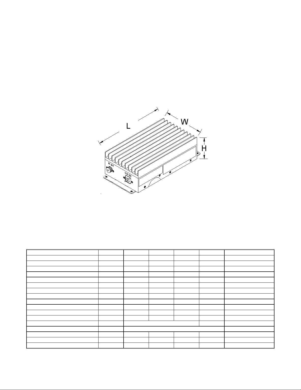
interior of a car or in the trunk. The amplifier’s dimensions are: 9.5”L x 3.0”H x
4.5” W (see figure 1) and the weight is 4 lbs.
Figure 1. Dimension (D package).
II. GENERAL SPECIFICATIONS
ELECTRICAL SPECIFICATIONS @ V
Parameter Symbol Min. Typ. Max. Unit Condition
Frequency Range BW 136 174 MHz
Operating bandwidth within range OBW 38 MHz
Input Power PIN 1 10 Watt Model dependant
Output Power P
Output Flatness ΔP
Gain G
Duty Cycle D 40 % per EIA/TIA-603-C
Harmonic Emissions Har -67 -62 dBc P
Spurious Emissions Spur -78 -72 dBc P
Operating Voltage VDD 11 13.8 15 Volt
Supply Current IDD 8 10 Amp P
Input VSWR S11 1.3:1 2:1 VSWR
Operating Mode Mode FM/CW
Emission Designators ED F1E, F1D, F1W, F3E, F2D, F7W, FXD, FXE
Input / Output Impedance Z
Receive Path Insertion Loss IL 0.5 1 dB
SSR Attack Time t
= 13.8 VDC Nom., TA = +25° C
DD
15 60 70 Watt See Note 1
OUT
OUT
50 Ω
IN / ZOUT
100 250 μS
ATK
±0.5
12
dB
dB
OUT
OUT
OUT
= 60 W
= 60 W
= 60 W
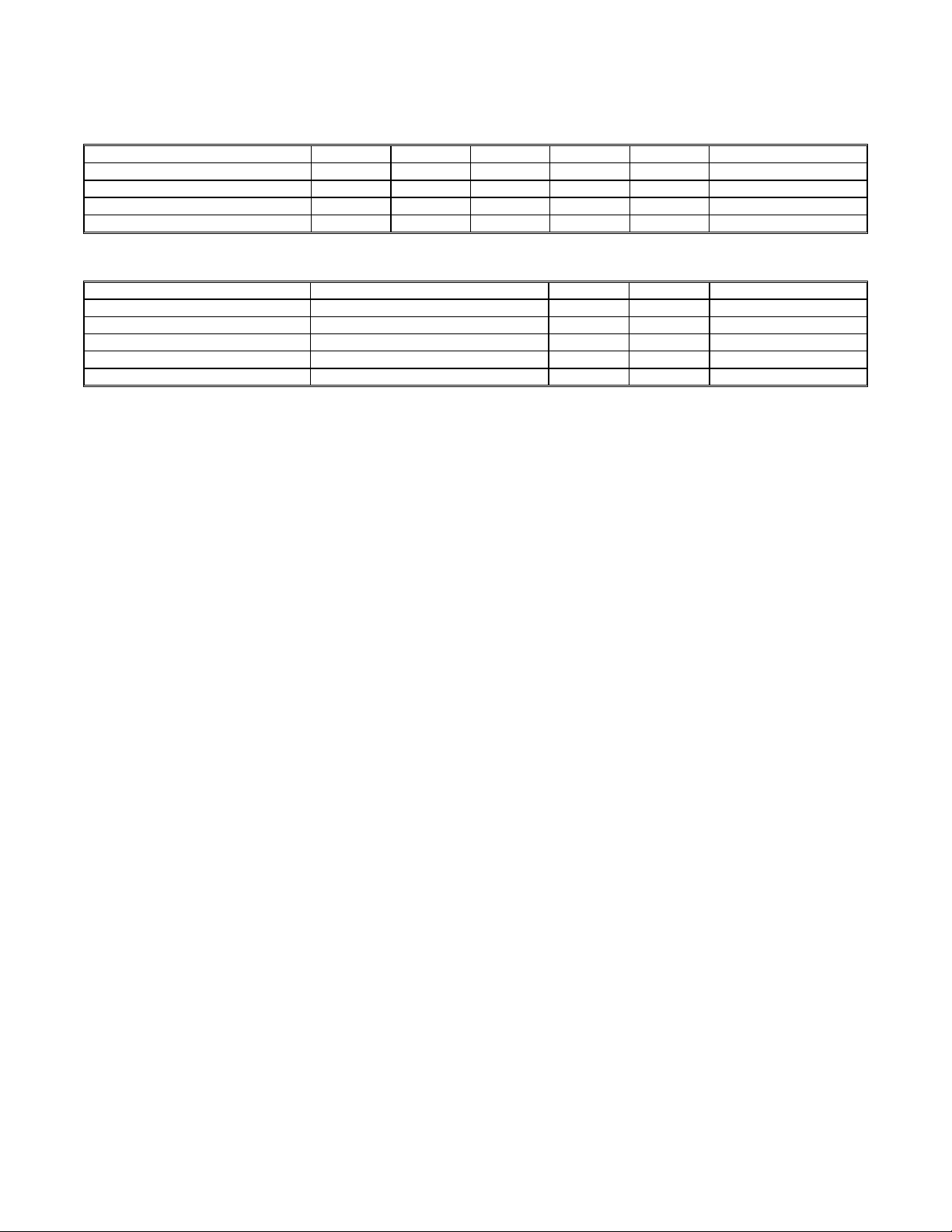
ENVIRONMENTAL CHARACTERISTICS
Parameter Symbol Min. Typ. Max. Unit Condition
Operating Temperature TO -20 +50 °C
Storage Temperature TS -40 +85 °C
Operating Humidity HO 0 85 %
Storage Humidity HS 0 95 %
MECHANICAL PROPERTIES
Parameter Value Units Limits Condition
Dimensions 9.5 L x 3.0 H x 4.5 W inch max
Weight 4 lb max
RF Connectors, In/Out UHF (SO-239) Type N optional
DC Connector Cinch 4-pin male
Cooling Convection
relative, non-condensing
relative, non-condensing
NOTES:
1. The rated output power of this amplifier is for single carrier operation.
For situations when multiple carrier signals are present, the rating would
have to be reduced by 3.5 dB, especially when the output signal is reradiated and can cause interference to adjacent band users. This power
reduction is to be by means of input power or gain reduction and not by
an attenuator at the output of the device.
OPERATING VOLTAGE:
Nominal DC operating voltage is 13.8VDC and the specifications are given
at this voltage, as measured at the DC input connector. Reduced DC input
voltage will result in lower output power and efficiency.
EIA DUTY CYCLE:
NOTE: Use of TPL Mobile Amplifiers above the recommended duty cycle
or in repeater applications is not recommended and voids the warranty.
CONFIGURATION:
All mobile amplifiers are supplied with Solid State Carrier Operated
Relay (SSR).
 Loading...