

Page 1

460 Handheld 20MHz
Digital Oscilloscope
User’s Guide
Test Products International, Inc.
9615 SW Allen Blvd.
Portland, OR 97005
Ph: 503-520-9197 ! Fax: 503-520-1225
E-mail: info@tpi-thevalueleader.com
The Value Leader
www.tpi-thevalueleader.com
TM
Page 2

Copyright © 2001
Test Products International, Inc.
All Rights Reserved
08/01
460 User’s Guide
ii
Page 3

Table of Contents
C1 - Introduction........................................................................................C1-1
Features ..........................................................................................C1-2
Specifications ..................................................................................C1-3
Scope Modes ........................................................................C1-3
Multimeter Modes ................................................................C1-5
C2 - Getting Started ..................................................................................C2-1
Equipment Needed ..........................................................................C2-1
460 Setup ........................................................................................C2-1
Measuring Voltage ..........................................................................C2-3
Measuring Frequency ......................................................................C2-3
Measuring Resistance......................................................................C2-4
Testing Continuity ............................................................................C2-4
Diode Test ........................................................................................C2-4
C3 - Operation............................................................................................C3-1
Principal Connectors and Keys ........................................................C3-1
Key / Screen Menus ........................................................................C3-3
C4 - Advanced Functions ..........................................................................C4-1
Triggering ........................................................................................C4-1
Trend Mode......................................................................................C4-1
Glitch Capture ..................................................................................C4-2
Saving Screens ................................................................................C4-2
Using the 10:1 Probe ......................................................................C4-3
10:1 Probe Compensation Adjustment ............................................C4-3
C5 - Using Adapters ..................................................................................C5-1
Temperature Adapter - A301............................................................C5-1
High Current Adapter - A251 / A256 / A296 ....................................C5-1
Low Current Adapter - A254 ............................................................C5-2
460 User’s Guide
iii
Page 4

Current Shunt Adapter - A130 ........................................................C5-2
Pressure Adapter - A620 ................................................................C5-2
PC Software & RS232 Cable - A404................................................C5-3
C6 - Safety Considerations ........................................................................C6-1
Instrument ......................................................................................C6-1
Environmental..................................................................................C6-2
Appendix A - Test and Calibration................................................................A-1
Appendix B - Maintenance Considerations ..................................................B-1
Appendix C - Glossary ................................................................................C-1
Appendix D - Optional RS-232C / PC Interface............................................D-1
Appendix E - Troubleshooting ......................................................................E-1
iv
460 User’s Guide
Page 5

Chapter 1
Introduction
This manual describes the TPI Scope Plus 460 and its functions. Normal and advanced functions
are covered in detail, as well as interactions with computers and other instrumentation. A full
chapter is also devoted to safety considerations, both instrument based and interactively. The following is a brief chapter and appendix summary:
Chapter 1 - Covers the introduction, features and Specifications.
Chapter 2 - Getting Started gets the new user up and running in the shortest time possible.
The basic functions are introduced in a hands on style designed to familiarize the
user with the keypad and screen display.
Chapter 3 - Explains all the normal functions of the TPI Scope Plus 460, including buttons,
menus, screen displays, and a sequencing guide for both external key actions and
their interaction with software driven menus.
Chapter 4 - Explains more advanced functions such as triggering, glitch capture, trend mode,
and saving screens.
Chapter 5 - Explains and illustrates uses of probes and adapters including pressure,
temperature, and current shunt adapters. This chapter also introduces general
aspects of the optional optically isolated RS-232 interface.
Chapter 6 - This important chapter details operating methods and tips designed to preserve
both the life of your instrument, and safety factors to prevent human injury. The
text is divided into Instrument and environmental safety subsections.
Appendix A - This appendix covers what to look for, and how to make simple tests to find out if
your TPI Scope Plus 460 requires replacement parts or calibration.
Appendix B - This Maintenance appendix gives tips on how to keep your TPI
Scope Plus 460 in top operating condition by assuring constant
peak performance. The appendix also covers battery servicing
and replacement.
Appendix C - A glossary describing the meanings of terms associated with the
460 and its working environment.
Appendix D - This appendix introduces and explains the powerful RS-232C
Interface option. All aspects are covered from Installation to
460 User’s Guide Introduction
C1-1
Page 6

Special Applications.
Appendix E - This Troubleshooting appendix covers problems that may arise
during installation or operation of your new TPI Scope Plus 460.
Features
The following features exist for the TPI Scope Plus 460:
"
20 MHz Bandwidth
Enough bandwidth to capture signals from AC/DC drive motors, sensors,
actuators, line and control voltages, UPS and industrial machines.
"
Sample Rate
A real time sampling of 25 megasamples/sec to capture spikes and dropouts of
industrial signals.
"
Dual Input
View two waveforms on the display for comparison and troubleshooting.
"
True RMS DMM
Includes a 4000 count True RMS DMM that measures AC/DC volts to 600V,
frequency to 20MHz, resistance to 20M Ohm, diode test and continuity audible
tone.
"
Autoranging
Autoranging capability across Voltage, Timebase and Frequency.
"
Bright LCD Backlight
Easy-to-see display in any light condition with user-adjustable backlight
brightness levels
"
Optically Isolated RS232 Output
Transfer data safely without any direct connections to your computer’s systems
security.
"
Optional Accessories
Temperature Adapter to measure temperature from -40 to 500
o
F (A301).
Pressure Adapter to measure pressure from -30 to 500psi (A620).
Protective Boot (A405).
Soft Carrying Case with Shoulder Strap (A905).
RS232 cable and software (A404).
Current Adapters:
o A254 - For measuring low current in milliamps
o A256 - Up to 400 AC/DC amps
460 User’s Guide Introduction
C1-2
Page 7

o A296 - Up to 1000 AC/DC amps
Specifications
Display:
Size 76mm X 76mm (3" X 3")
Pixels 240 X 240 pixels
LCD type STN Normally Gray or Black
Back Light CCFL
Memory:
Waveform Screens (2)
Setup User setup (1)
Power:
External Power Adapter (5.5V / 2A)
Internal Battery Ni-MH 1.2V X 4
Battery Operating Time More than 2.5 hours with bright backlight
Charging Time 10 hours
SCOPE MODES
Horizontal:
Samples per division 25 samples / div.
Time/division Equivalent sampling 50ns to 500ns/div
Real time sampling 1us to 2s/div
Modes Single, Normal, Auto, Glitch
Accuracy Real time sampling +/- (0.1% + 0.04 time/div)
Equivalent sampling +/- (0.5% + 0.08 time/div)
Vertical:
Sampling Rate 25 Mega samples per second
Bandwidth DC Coupled 1:1 shielded test leads ; DC to 10MHz
10:1 probe ; DC to 20MHz
AC Coupled 1:1 shielded test leads ; 10Hz to 10MHz
10:1 probe ; 10Hz to 20MHz
Resolution 8 bits
Channel 2
Coupling AC,DC,GND
Input impedance Approx. 1M Ohm
Sensitivity 50mV to 200V/div 1,2,5 sequence
460 User’s Guide Introduction
C1-3
Page 8

Accuracy +/- (3% + 0.05 range/div)
Display modes CH1, Dual
Maximum Input Voltage 600V
Trigger:
Position Ver 1; Fixed Position / Ver 3; Adjustable Position
Mode Free run, normal
Source Internal (CH1/CH2)
Slope Positive/Negative
Sensitivity Real time sampling .... 2 divisions or more
Equivalent sampling .... 3 divisions or more
Trend Plot:
Plot Time 30sec/div to 1-hour/div
Plot Data Type Max / Min Selectable
Temperature Measurement:
Optional Adapter A301 (k - Type thermocouple)
Range -40 F to 500 F
Accuracy +/- (1.5% + 5 digits)
Pressure / Vacuum Measurement:
Optional Adapter A620
Range Pressure 500 psi
Vacuum 30 inHg
Accuracy Pressure +/- (5% + 5 digits)
Vacuum +/- (1.5% + 5 digits)
Current Measurement:
Optional Adapter 1 A251 (AC AMPS)
Range 0 - 40A / 40 - 400A
Accuracy ( 0 - 40A ) +/- (2.0% + 10 digits , 50 / 60 Hz)
(40 - 400A) +/- (2.0% + 10 digits , 50 / 60 Hz)
Optional Adapter 2 A256 (AC/DC AMPS)
Range 0 - 40A / 40 - 400A
Accuracy ( 0 - 40A ) +/- (2.0% + 10 digits , 50 / 60 Hz)
(40 - 400A) +/- (2.0% + 10 digits , 50 / 60 Hz)
Optional Adapter 3 A296 (AC/DC AMPS)
460 User’s Guide Introduction
C1-4
Page 9

Range 0 - 400A / 400 - 1000A
Accuracy ( 0 - 400A ) +/- (2.0% + 10 digits , 50 / 60 Hz)
(400 - 1000A) +/- (2.0% + 10 digits , 50 / 60 Hz)
MULTIMETER MODES
DC Volts (CH1/CH2)
Range Resolution Accuracy
400mV 0.1mV +/- (0.5% + 5 digits)
4V 0.001V +/- (0.5% + 5 digits)
40V 0.01V +/- (0.5% + 5 digits)
400V 0.1V +/- (0.5% + 5 digits)
600V 1V +/- (0.5% + 5 digits)
AC Volts (CH1/CH2)
Range Resolution Accuracy
400mV 0.1mV 20Hz to 50Hz; +/- (2% + 20 digits)
4V 0.001V 50Hz to 1kHz; +/- (1% + 10 digits)
40V 0.01V 1kHz to 20kHz; +/- ( 2% + 10 digits)
400V 0.1V 40Hz to 400Hz; +/- (1% + 10 digits)
600V 1V 40Hz to 400Hz; +/- (1% + 10 digits)
Frequency (CH1/CH2)
Range Resolution Accuracy
100Hz 0.01Hz +/- (1.0% + 10 digits)
1KHz 0.1Hz +/- (0.5% + 5 digits)
10KHz 1Hz +/- (0.5% + 5 digits)
100KHz 10Hz +/- (0.5% + 5 digits)
1MHz 100Hz +/- (0.5% + 5 digits)
10MHz 1kHz +/- (0.5% + 5 digits)
20MHz 10kHz +/- (2.5% + 5 digits)
OHM (CH1 ONLY)
Range Resolution Accuracy
400 Ohm 0.1 Ohm +/- (0.75% + 5 digits)
4k Ohm 1 Ohm +/- (0.5% + 5 digits)
40k Ohm 10 Ohm +/- (0.5% + 5 digits)
400k Ohm 100 Ohm +/- (0.5% + 5 digits)
4M Ohm 1k Ohm +/- (1.0% + 10 digits)
20M Ohm 10k Ohm +/- (3.0% + 20 digits)
460 User’s Guide Introduction
C1-5
Page 10

Continuity (CH1 ONLY)
Range Resolution Accuracy
4 K ohm 1 ohm Beeps < 0.1 K ohm , +/- (2% + 5 digits)
Diode (CH1 ONLY)
Range Resolution Accuracy
4 V 1 mV Open circuit voltage < 5 V
Short circuit current < 5 mA
Reading accuracy; +/- (2% + 5 digits)
460 User’s Guide Introduction
C1-6
Page 11

Chapter 2
Getting Started
This chapter will get you started with the TPI Scope Plus 460. It will include initial power up, followed by a series of DMM and static tests. More detailed operations will be the subject of the
next chapter. Refer also to the chapters and appendices covering specifications and maintenance
if you run into problems outside the scope of this chapter. Also feel free to check with service
support using the phone numbers given at the beginning of this manual.
Equipment Needed
Required:
"
Fully operational TPI Scope Plus 460 with batteries fully charged
"
Set of probes with alligator clip attachments available
"
Set of fixed or variable resistances.
"
Set of fixed or variable inductances.
"
Set of fixed or variable capacitances.
"
Static or variable DC voltage source.
Optional:
"
Signal generator source with varied outputs
"
Random glitch or voltage spike generator
460 Setup
1. Use the tilt stand if necessary to set up the instrument in a readable position.
2. Switch the unit on by pressing POWER ON button for 3 seconds. If the unit will power
on, attach the power adapter. Initial charge of the battery must be made with 460 turned
on.
3. If the Power adapter is attached, check the battery level by pulling out the adapter and
checking if there is any change to the brightness of the display (For optimal performance,
the battery should be fully charged even with the Power adapter attached).
4. Check the Contrast. Refer to Figure 2-1, and press the USER button. Note the Contrast
menu button is displayed on the screen above F2. - Press F2 and note the menu item on
the screen is now darkened. Press the Up arrow to increase the contrast and the Down
arrow to reduce the contrast.
5. Check the Brightness (-there are ten levels). Refer to Figure 2-1, and press the
Brightness button (Sun Icon) to decrease the brightness. To increase the brightness,
continue pressing the brightness button until you have reached the bottom level, at which
460 User’s Guide Getting Started
C2-1
Page 12
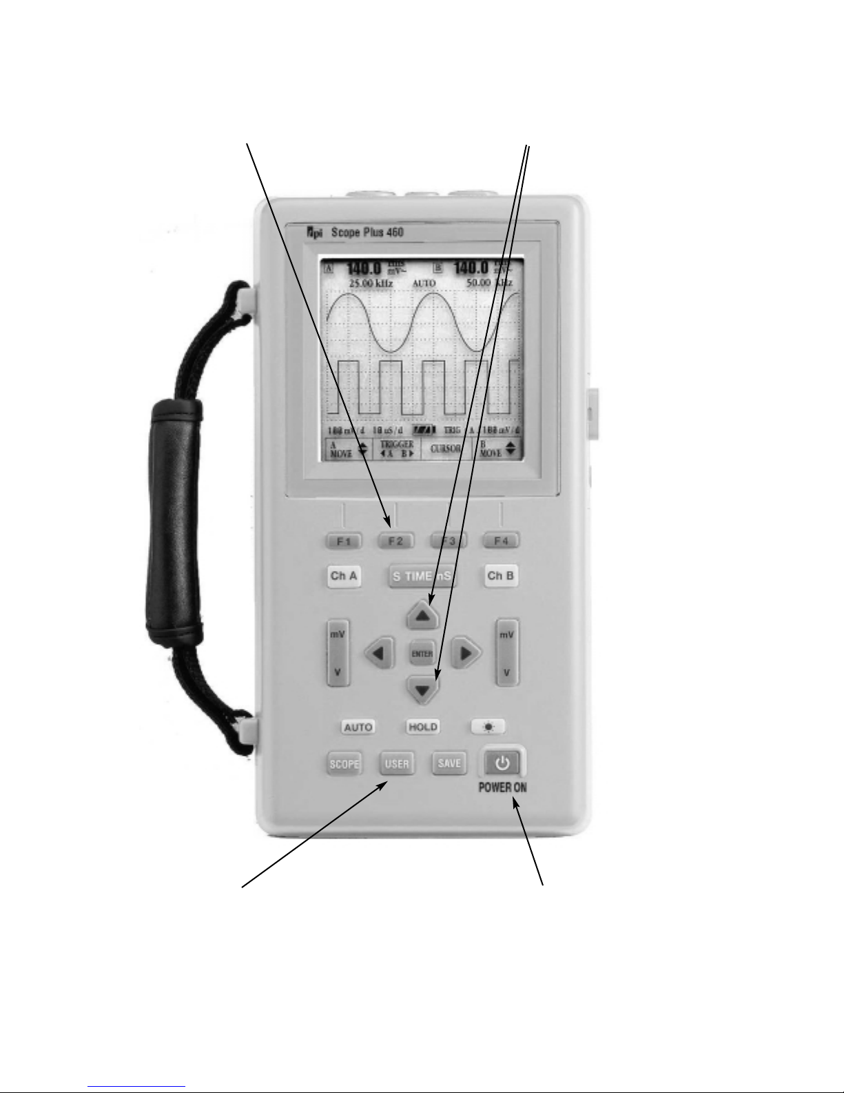
3. Press F2 (below the
Contrast Label).
4. Press the Up or Down direction
arrows to change contrast.
2. Press the User
Button
1. Press the POWER ON
Button
Figure 2-1. Contrast Adjustment with Low Visibility
460 User’s Guide Getting Started
C2-2
Page 13

time it will revert to the maximum brightness level.
NOTE: The Brightness control effects the backlighting whereas Contrast
effects the intensity of the liquid crystal display (both for the tracing beams
and the text display).
6. You have now completed the basic setup. Press Ch A (Channel A), to exit the user setup
mode and ready the instrument for Multimeter operations.
Measuring Voltage
1. With the 460 set for Input A (Ch A button), use the down arrow to set the highlight on
DCV. Press Enter.
2. Press the green V key, and connect the probes to a DC Voltage source. The voltage will
appear in alphanumeric text at the top left of the screen. The trace line A should be
steady, but if there are any AC components present on the line it will also show these
(especially in the case of partially rectified AC).
NOTE: Pressing the Green key V selection first will ensure you are not
being limited by the millivolt range. If the voltage reading is then read as
a small value, use the mV side of the green rocker key to display the millivolt
range on the screen.
3. Disconnect the DC Voltage source and press Ch A (Channel A blue button). Use the Up
arrow to move the screen highlight to ACV. Press Enter.
4. Press the green V key, and connect the probes to the AC source. The voltage can be read
at the top left of the screen expressed as an RMS value. The trace line A will show the
shape of the AC voltage source.
Measuring Frequency
1. With the 460 set for Input A (Ch A button), use the down arrow to set the highlight on
Freq. Press Enter.
2. Connect the probes to a frequency source. The frequency will be shown in alphanumeric
text at the top left of the screen. The trace line A will show the nature of the frequency
source.
Notes on Trace Stability:
a). Ensuring that the Channel B trace is off when making frequency
measurements on the A channel, will reduce clutter on the screen, and make
the A trace easier to read.
460 User’s Guide Getting Started
C2-3
Page 14

b). Using the HOLD/RUN button will freeze the trace and allow waveform
characteristics to be measured precisely against the background grid.
Measuring Resistance
1. With the 460 set for Input A (Ch A button), use the down arrow to set the highlight on
OHM. Press Enter.
2. Connect the probes across the resistance source. The resistance value is shown in two
forms. First as alphanumeric text at the top of the screen. Secondly, the value is shown
visually against a calibrated bar. The value of the bar is shown at the base of the screen.
For instance, if a resistance of 12.00 K Ohms is being read, a bar of value 40K Ohms will
typically be displayed, and the actual value of the resistance will show as 12.00 against
that bar
Testing Continuity
1. With the 460 set for Input A (Ch A button), use the down arrow to set the highlight on
Beep. Press Enter.
2. Connect the probes across the source to be tested. If the line is closed (equiv. of short
circuit) or not offering more than 100 Ohms of resistance, the full beep will be heard, and
the bar will show the degree of resistance (if any).
Note: The continuity test function can also be used to test the resistance in
a path up to a value of 4K Ohms. The actual value will be shown alphanumerically in the top left of the screen, and also shown graphically against
a bar having a span of 0 to 4K Ohms
Diode Test
1. With the 460 set for Input A (Ch A button), use the down arrow to set the highlight on
DIODE. Press Enter.
2. Connect the probes across the diode in the +/+ direction. A total resistance should be
noted (The full bar shows no reverse current flow).
3 Connect the probes to the diode in the normal +/- direction. The bar display should show
an open or almost open condition. - Forward bias is shown against a scale of 2.0 volts
and is also displayed alpha-numerically at top left of the screen.
460 User’s Guide Getting Started
C2-4
Page 15

Chapter 3
Operation
This chapter provides a general overview of the tpi Scope Plus 460 from an operations point of
view. The keys and adapter connectors will first be identified followed by a pictorial description
of the key and screen menu functions.
Principal Connectors and keys
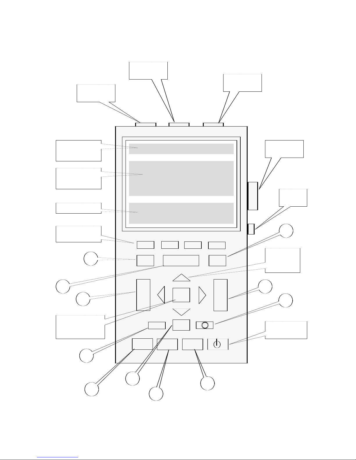
Figure 3-1 shows the general layout of the front panel and side connectors. Many of the functions are straight forward and identified in the illustration. The numbered items in the diagram
need additional explanation and are detailed below:
1. Ch A
This key controls the display of oscilloscope Channel A. The first screen requires
the user to first identify the nature of the display, e.g., AC Volts, DC Volts,
Frequency, etc. Then, after pressing ENTER, the Channel A trace is displayed as
well as the correct alphanumerics.
2. Ch B
This key controls the display of oscilloscope Channel B. The first screen requires
the user to first identify the nature of the display, This list is different from
Channel A and includes specialized measuring scales such as
o
C, oF and Psi, etc.
After selecting the scale, press ENTER , and the Channel B trace is displayed.
3. S TIME nS
This rocker switch controls the oscilloscope timebase. Pressing the left side
decreases the sweep rate in 1, 2, 5, increments down to 2-seconds per division.
Pressing the right side speeds the sweep rate in increments up to 50-nano
seconds per division. Sweep Rate is displayed above the TRIGGER label at the
base of the screen
4. mV / V
This vertically orientated rocker switch controls the vertical sensitivity for the A
Channel oscilloscope. The scale is in 1, 2, 5, increments from 50mV to 200V
per vertical division. The readout is at the extreme left of the display just above
the A MOVE label.
5 mV / V
This rocker switch is identical to Callout #4 except applicable to Channel B. The
readout is at the extreme right of the display just above the B MOVE label.
6. <Sun Icon>
This is the brightness button. It controls the screen background intensity of the
460 User’s Guide Operation
C3-1
Page 16
backlit LCD screen. The button has ten cycles of brightness, after which it resets
to the first position.
Figure 3-1. 460 Front Panel layout
Ch A COM Ch B
F1 F2
F3
F4
Ch A
Ch B
S TIME nS
ENTER
mV
V
mV
V
AUTO
HOLD
RUN
SCOPE
USER SAVE
POWER ON
Channel B
Connector
Channel A
Connector
Common
(Ground)
RS-232C
Connector
Power
Plug
Alphanumeric
Display Area
Dual Trace
Display Area
Menu Area
Menu Function
Keys (F1-F4)
Highlight
Direction
Arrows
460 Power
Switch
Function
Acknowledge
Key
1
3
4
2
5
6
7
8
9
11
10
460 User’s Guide Operation
C3-2
Page 17

7. AUTO
This is the Auto Ranging and optimal setting button. In the AUTO mode, the 460
will sense the parameter being measured and automatically adjust the oscilloscope
timebase to suit. The button also toggles between AUTO and MANUAL modes.
Note that the previous manual settings are lost once auto mode has activated.
8. SCOPE
This is a dual function oscilloscope switch. Initial activation (Scope /S1)
sets the oscilloscope program to display the SCOPE INPUTS interactive
menu. Activating the SCOPE switch a second time, sets the program to
display the Channel A waveform, the Channel B waveform (if it is
switched ON), and the A / B MOVE, TRIGGER / TREND selection menu.
Pressing the switch a third time will toggle the program back to SCOPE
INPUTS.
9. HOLD / RUN
This is a toggle switch that allows the user to freeze the currently dis
played waveforms. Once frozen, the user can choose to record the
waveform using the SAVE key (see callout #11), or to press the HOLD /
RUN key a second time to unfreeze the display.
10. USER
This is a toggle switch that allows a user to interrupt most ongoing
programs to revert to a setup mode to adjust Contrast, RS-232C output,
or Power Down, and then revert to the original program by pressing
the button a second time. Note that the POWER DOWN menu selection
allows an automatic timed power down for special functions.
11. SAVE
This is a toggle switch that allows a screen save (traces only) for a
maximum of two saves and/or recalls. You can delete an existing capture,
or automatically overwrite to the selected memory. Pressing the button
a second time reverts to the original display.
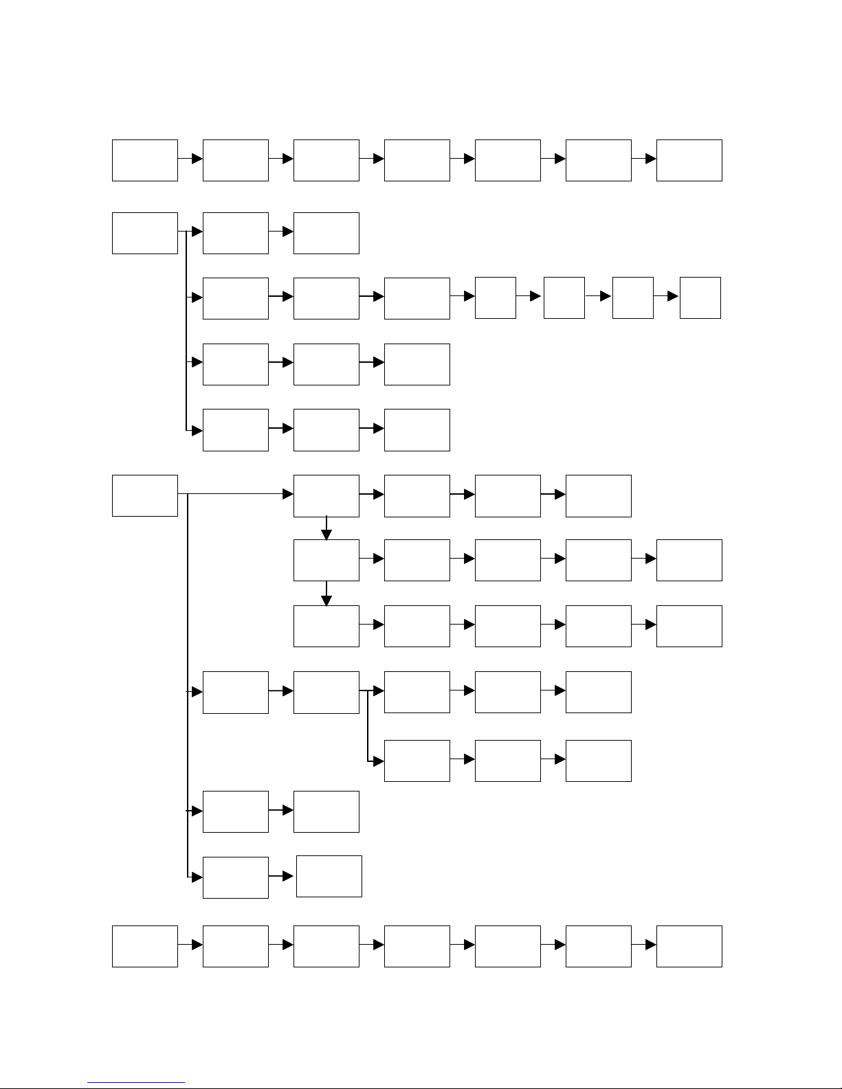
Key / Screen Menus
The following tables provide a graphical explanation of the key and menu interactions and menu
item sequencing. Most sequences begin with a key and are at the left of the diagrams. The colors of the keys are below the appropriate boxes.
Note that the two Scope entries (Scope / S1 in Table 3-1, and Scope / S2 in Table 3-2) represent
the two sequential functions of the same switch.
460 User’s Guide Operation
C3-3
Page 18
DIODECHA
ACV
DCV
FREQ OHM BEEP
CHB
OFF ON
Blue
Blue
ACV DCV FREQ
1mV/A 10mV/A
100mV
/A
1mV/A 10mV/A
100mV
/A
1mV
/
o
C
1mV
/
o
F
1mV
/Psi
1mV
/inHg
ACA
DCA
SCOPE
/ S1
F1
F2
F4
A
ACV
DCV GND
GLITCH
MODE
AUTO NORM SINGLE
Brown
OFFB ACV DCV GND
PROBES
SELECT
SEL B 1:1 10:1
SEL A 1:1 10:1
Probe
Adjust
Enter
NOSAVE
SAVE
RECALL DELETE
SCREEN
1
SCREEN
2
Brown
Table 3-1. 460 User Function / Menu Interactions – Part 1
460 User’s Guide Operation
C3-4
Page 19
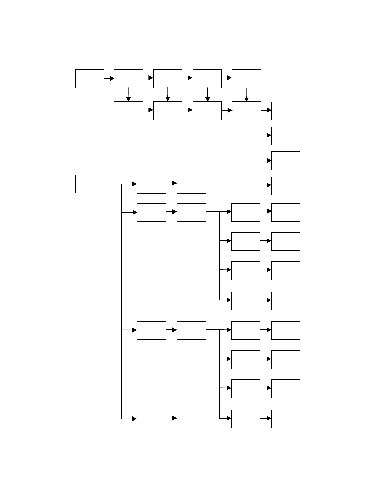
USER
F1
F2 F3 F4
EXIT
Brown
SCOPE
/ S2
F1
A
MOVE
F2
TRIGG-
ER
F1 EXIT
Brown
F2
SOURCE
A, B
F4
TRIG.
SLOPE
F3
TRIG.
LEVEL
Table 3-2. 460 User Function / Menu Interactions – Part 2
CON-
TRAST
RS-
232C
POWER
DOWN
F3
TREND
F1 EXIT
F2
MAX
F4
RE-
START
F3
MIN
F4
B
MOVE
AFTER
10 MIN
AFTER
20 MIN
AFTER
30 MIN
DIS-
ABLE
460 User’s Guide Operation
C3-5
Page 20

Page 21

Chapter 4
Advanced Functions
This chapter assumes the user has now become proficient with the general use of the tpi Scope
Plus 460, and is ready to utilize the more enhanced operations of the 460’s built-in oscilloscopes
and related logic circuits.
In this chapter we will look at triggering, trend mode and different aspects of capturing glitches.
We will also look at screen saves, use of the 10:1 probe and probe adjustments.
Triggering
Trigger level refers to the control of the threshold voltage amplitude level that is triggered from
the input signal, in turn synchronizing the waveform. Once the voltage exceeds or recedes the
trigger level, the meter will draw a trace of the signal with greater stability allowing the technician
to analyze the portion of interest more efficiently.
With Channel A on the 460 active, connect the Common and Probe Lead A to a signal source
(Sine Wave preferred), and proceed with the following steps:
1. Click SCOPE, then select A=ACU, Mode=Auto, B=Off. Then select ENTER
2. Move the highlight to TRIGGER and press ENTER
3. Use the mV / V Channel A rocker key to size the waveform.
4. With the highlight on TRIG. LEVEL, use the up and down keys to stabilize the waveform.
5. Observe that you have now stabilized the waveform without changing the frequency and
without intentionally freezing the waveform. So this is a stabilized live waveform suitable
for analysis or monitoring.
6 Use the SOURCE or TRIG. SLOPE highlight options in conjunction with the direction
buttons to modify the waveform.
7. Use the EXIT box (F1) to Exit from the trigger operation and / or to move the
waveform position on the screen.
Trend Mode
The Trend mode graphs signals over time to capture problems. This option has menu
boxes but is inactive on the current model of the 460.
460 User’s Guide Advanced Functions
C4-1
Page 22

Glitch Capture
The tpi Scope Plus 460 incorporates this feature for capturing intermittent or single event voltage
spikes occurring in a circuit. The spike is automatically detected, captured, and displayed for
analysis on the screen.
To perform this task as a test, you will need a signal generator with a spike or glitch generating
capability, or a means of imposing a glitch onto an otherwise stable signal.
With Channel A on the 460 active, connect the Common and Probe Lead A to a signal source
(Sine Wave preferred), and proceed with the following steps:
1. Click SCOPE, then select A=DCU, Mode=Glitch, B=Off. Then select ENTER
2. Use the up and down keys to center, or lower the waveform (-the spike will usually be
positive in test cases). Then introduce the spike (-this is usually a button on many test
signal generators).
3. If the 460 is performing correctly, you should now have the glitch on your screen,
complete with leading and trailing edges so that rise time as well as other parameters
can be measured.
4. Exit the glitch condition by selecting SCOPE, then change MODE = NORM, then press
ENTER.
Saving Screens
You can save any screen capture from Channel A, Channel B, or two instances of both channels
simultaneously. They can be recalled to the screen, or made available to your computer if you
also have the RS232 software option.
As an example of simultaneous capture, connect the Common and Probe Lead Ch A to one signal
source, then the Probe lead Ch B to a different signal source, and proceed with the following
steps:
1. Click SCOPE, then select A=ACU, Mode=Glitch, B=ACU. Then select ENTER
2. Use the up and down keys in conjunction with the A & B Move boxes at the base of the
screen to position both waveforms
3. Press the SAVE key, select SCREEN 1, and then select ENTER
460 User’s Guide Advanced Functions
C4-2
Page 23

NOTE: There may be no change to the screen after the last operation. This
is normal.
4. Press SAVE again, then select the menu item RECALL, then SCREEN 1, then ENTER.
5. You should now see your saved waveforms with the label RECALLED SCREEN 1,
immediately below the waveforms.
NOTE: The next screen save using the same screen number (e.g. Screen 1), will
overwrite the previous (Screen 1) save.
6. Select the on-screen EXIT to leave the Save program, then press SCOPE to reset the
scope parameters
Using the 10:1 Probe
The TPI Scope Plus 460 is also available with selectable attenuation probes (e.g. P/N SP60B).
These are usually in the form of a probe body with a 3-position switch, 1-meter co-axial lead terminating at the meter end with a BNC connector with an adapter for the 460 socket. This set-up
contains its own ground lead exiting from the probe body, and is supplied with a number of different probe tips.
Attenuation selection is X1, X10, and a ground reference position. Use of the 10:1 probe extends
the bandwidth to 100 MHz when used in the X10 position.
To use the 10:1 probe with the 460, press the SCOPE button, then the F1 key when the SCOPE
INPUTS / PROBES SELECT menu boxes are present on the screen.
With the 10:1 Adapter in the CH A socket, use the Up / Down keys to highlight 10:1 on the SEL A
side of the displayed Probe Selection menu box. Then select ENTER
When using the 10:1 probe on different dual oscilloscope channels, or from instrument to instrument, always perform the adjustment procedure which follows.
CAUTION: Do not use the 10:1 probe for resistance measurements.
10:1 Probe Compensation Adjustment
The following adjustment procedure will ensure that the displayed waveforms will be matched to
the correct division on the display.
There are two methods to compensate the 10:1 Probe. The first and recommended way is to
460 User’s Guide Advanced Functions
C4-3
Page 24

connect the probe to the 460 and set up a 1 KHz square wave using an external signal generator.
Method 1
1. Connect the 10:1 Adapter BNC connector to the Ch A socket on the 460.
2. Press the 460 SCOPE key. Then, when the SCOPE INPUTS display is present, press the
F2 key below the PROBE ADJUST selection box.
3. Attach the 10:1 Probe tip to the signal generator, and use the ground wire from the probe
body to connect with the signal generator ground.
4. With a square wave displayed on the 460 screen, adjust the trimmer located in the BNC
plug to maximize the squareness on the top and bottom of the square wave.
5. On the 460, press the F4 key, or the ENTER key to exit the program.
Method 2
1. Connect the 10:1 Probe BNC adapter to the Ch B input at the top of the 460. Then attach
the 10:1 Probe Tip with the Banana Adapter to the Ch A input.
2. Press the SCOPE key. Then, when the SCOPE INPUTS display is present, press the F2
key below the PROBE ADJUST selection box.
3. Following the instructions on the screen, use the screwdriver, supplied with the 10:1
Probe kit to adjust the trimmer in the BNC plug. Adjust the trimmer to obtain fully
squared edges on the displayed square wave.
4. On the 460, press the F4 key, or the ENTER key to exit the program.
460 User’s Guide Advanced Functions
C4-4
Page 25

Chapter 5
Using Adapters
This chapter covers general information on the accessories available for use with the tpi 460
Handheld Oscilloscope. For detailed information, please refer to the data sheets provided with
each adapter.
Temperature Adapter - A301
This adapter is used in conjunction with K-type probes to measure a variety of temperature targets with ranges from -40 to 500oF. tpi offers almost 20 different types of thermocouple probes
that work accurately with the A301.
The A301 (regardless of the type of thermocouple use, has a standard output of 1mV DC per
degree Fahrenheit. The range of the A130 is -40 to 500
o
F, therefore the output range is 960mV to
O.5V. On the 460 this equates to using the standard DCV scale on Channel A, or the 1mV/oF
scale on the B Channel (Press Ch B, make selection, and press F4 to Enter).
NOTE: The A Channel is recommended for this adapter, as the Ch A plug
orientation on the 460 allows the Adapter On/Off switch to face the user.
The A301 comes with a 9V battery and a standard 2-Pin plug that sockets directly into the top of
the tpi Scope Plus 460.
High Current Adapters - A251 / A256 / A296
o A251 - A clamp-on adapter that measures up to 400 AC amps.
o A256 - A clamp-on adapter that measures up to 400 AC and DC amps.
o A296 - A clamp-on adapter that measures up to 1000 AC and DC amps.
All three adapters have some common operating parameters. They should only ever be used on
a single wire. Clamping onto bundles or any more that one wire will result in erroneous readings.
Set up the 460 before making the test and ensure that power is initially off to the circuit under
test and that the input cable is inserted using the correct polarities.
On the 460, use ACV for making AC measurements, and DCV for making DC measurements. In
addition, use the V rocker button on he instrument to initially go to the highest voltage rating
when making an initial measurement (200V on both scales).
All the High Current measurement adapters use a 9V battery (supplied). If the battery runs low,
460 User’s Guide Using Adapters
C5-1
Page 26

the red LED will come on and remain on until it is exhausted or the battery is replaced.
Low Current Adapter - A254
This small clamp-on adapter measures currents one amp and below accompanied by voltages up
to 1000V in either AC or DC.
Plug the unit into the upper sockets of the 460. Use DCV on Channel A (Ch A) and convert 10mV
to 1.0 amp with the 254 set to 10mV/A and 100mV to 1.0amp with the 254 set to 100mV/A, or
Channel B (Ch B) and use either the 10mV/A DCA or 100mV/A selections (depending on the
appropriate A254 setting) to read both millivolts and equivalent amps at the top of the screen.
Be sure to plug the A254 into the correct sockets of the 460 for the channel being used.
CAUTION: This adapter is designed to measure currents up to 1 Amp.
Attempts to measure currents greater than 60 Amps could damage both
the adapter and the 460 measuring instrument.
The A254 uses a 9V battery (supplied), and includes a detachable instrument head socket (2-pin
to co-axial), and a zero adjust control.
Current Shunt Adapter - A130
This adapter is an inexpensive way of extending the current range of your tpi 460 Handheld
Oscilloscope to 30 amps.
The A130 comes with two probes and is used in series with the circuit to be measured. The unit
uses the power being measured and requires no batteries.
Plug the unit into the upper sockets of the 460. Use DCV on Channel A (Ch A) and convert
0.1mV to 0.1 amp, or Channel B (Ch B) and use the 1mV selection to read both millivolts and
equivalent amps at the top of the screen.
Be sure to plug the A130 into the correct sockets of the 460 for the channel being used.
NOTE: Channel A is recommended for the A130 adapter, as the Ch A plug
orientation on the 460 allows the Adapter On/Off switch to face the user.
Pressure Adapter - A620
This adapter can measure air densities from a vacuum of 30 inHg to a pressure of 500 psi.
Connect the adapter to the upper sockets of the 460. Use DCV on Channel A (Ch A) and convert
0.1mV to 1 psi for pressure and 1 inHg for vacuum, or Channel B (Ch B) using the 1mV/PSI or
460 User’s Guide Using Adapters
C5-2
Page 27

1mV/inHg selections as required.
On the A620, use the BAR switch position to measure vacuum or the X10psi position to measure
pressures from 1 to 500psi. Use the ZERO control only if you know the pressure to be zero and
stable, or at a standardized pressure.
The A620 uses a 9V battery (supplied) and includes a 1/4 inch NPT pressure port connection at
the end of a 2-Meter flexible cable.
PC Software and RS232 Cable - A404
This software allows the 460 to download data and waveforms to any computer environment running Microsoft Windows. The RS232 interface utilizes a fiber optic connection to shield the data
from electro magnetic radiation sources, and therefor from potential signal degradation.
Using the A404 package you can download data and put the information into spreadsheets and
charts for incorporating into reports and other documents. Reports from different units can also
be merged to produce one report.
In addition, graphs can be shown with the identification number of the instrument used, enabling
data to be cross-checked against calibration records helping to ensure full traceability.
Since live waveforms can also be transmitted to the computer via the RS232 connection, you can
compare stored waveforms to current waveforms for some types of fault recognition.
Refer to Appendix D for RS232 interactions with your personal computer.
460 User’s Guide Using Adapters
C5-3
Page 28

Page 29

Chapter 6
Safety Considerations
This chapter deals with various aspects of safety, both for personnel and the instrument. Also
included is a List of safety signals and their meanings.
Instrument Cautions
o Test the Instrument before using
o Check Backlighting and Contrast (this will also accomplish a quick test on the
battery level).
o Check both oscilloscope channels. - A simple standard waveform test will usually
accomplish this.
Check the Test Leads and/or Adapter
o If there is a break or intermittent in the test leads, it will have the same effect as a
malfunctioning instrument.
o Check the adapter using a known sample or set-up before using on the device or
environment under test.
o Test Connections
o Check the security and quality of both the adapter connections to the instrument and
DUT (Device Under Test) connector points.
Disconnect Power to the Circuit (Unless using Clamp-On’s)
o This step provides two safety factors. The first ensures that the operators hands are
not in the vicinity of dangerous voltages. The second allows you to check that the
instrument is set up to read the right values before power is present at the DUT.
o Understand the circuit being measured
o Failure to understand the circuit to be tested has the same level of risk as not setting
up the instrument before power is applied to the circuit. Namely the risk of too much
power for the level of measurement.
Keep the Instrument Non-Parallel to the Circuit
o If the instrument, or any substantial length of test cable is parallel to and/or in close
proximity to the bulk of the DUT or high current carrying cable, the test cable will
pick up some of the radiation and be affected by it. This is important when making
precise measurements or when seeking a stable waveform.
460 User’s Guide Safety Considerations
C6-1
Page 30

Personnel/Environmental Factors / Warnings
Assign a Checker
o Arrange to have someone check on you periodically. This is especially true of high
voltage environments. An unconscious worker stands a better chance of survival if
resuscitation is given in the shortest time after an accident.
Do not attempt to measure unknown voltages or currents
o With modern cabling, it is easy to assume that a small size wire or cable is carrying a
voltage or current that is less than actual. Either assumption can have disastrous
effects for both operator and instrument.
Do not touch any exposed part of the test lead assembly
o Some types of test leads have close to exposed metal parts that could potentially
come into contact with the body, especially hands or lead pencils and other
conducting items.
List of Danger/Warning Signals
The following are International Danger/Warning signals with an abbreviated explanation of their
meanings.
This label signifies that there is a distinct level of danger in
this area. This sign is usually accompanied with symbols
denoting the exact type of danger present.
This combination label signifies that a significant level of
danger exists in this area that can effect the eyes. This
symbol denotes that shaded goggles should be worn.
This combination label signifies that there is a distinct
possibility of a fire hazard in this area (--an explosion
symbol is sometimes substituted for the fire symbol in
similar situations). Do not carry combustible materials in
this area
460 User’s Guide Safety Considerations
C6-2
Page 31

This combination label signifies that there is a strong
possibility of electrical shock in this area. Proper attire,
and especially insulated footwear are required in these
areas.
This International symbol signifies that conditions exist that
could result in bodily harm. The symbol usually occurs in
conjunction with a symbolic description of the type of
hazard that exists.
This symbol indicates that there are open gears in the area
which could snag clothing and risk injury to the wearer.
Avoid wearing loose clothing and beware of test instrumentation with long leads attached.
This symbol indicates that a hazard exists in this area which
could effect exposed skin areas. The nature of this hazard
could be chemical of temperature based. Wear gloves at all
times and be careful of any other skin contact.
This International symbol indicates that a danger exists
which could damage equipment that you carry into the
area. Identify proper grounding and use in conjunction with
test equipment at all times
460 User’s Guide Safety Considerations
C6-3
Page 32

Page 33

Appendix A
Test and Calibration
This chapter is designed to re-affirm that your TPI Scope Plus 460 is functioning correctly and is
on a par with the original calibration. This test and calibration procedure can be used as an
annual test, goods inward (Acceptance) test, or re-affirmation test when readings have not been
expected ones.
Test Procedures
The TPI Scope Plus 460 has no built-in test programs, however, the following procedures can be
used to perform a quick functional check on most 460 operations. Procedural titles that are followed by an asterisk (*) are less important, and can be considered optional in cases where a
quicker spot test is required.
Initial Setup
The following tests should be made with an adequate battery charge and with the power charge
plug in place, and the RS232 cable disconnected. If the battery has previously been low, allow at
least 15-minutes for the battery charge to build up.
On power up (press and briefly hold the POWER ON button), allow a further 5-minutes for the
circuitry, and LCD screen to stabilize. After stabilization, press USER, then F2 to arrive at CON-
TRAST. Press ENTER, and use the Up / Down keys to adjust for optimal contrast. One way to do
this is to press the Up arrow until the background begins to darken and then backtrack down by
pressing the down arrow once. In any case , the waveform and alphanumeric characters should
both be black and stand out in strong contrast to the background
Check the brightness by pressing the blue button with the Sun icon. Continue pressing. After
10-counts, it should resume to maximum brightness.
If any of the above steps perform unsatisfactorily, you either have an undercharged battery, or a
malfunctioning LCD display. Check with the service department (see phone numbers on Page 1
of this document), before returning the unit.
A-1
460 User’s Guide Test and Calibration
Page 34

Sequencing Test
This test will verify that the internal multiplexors are correctly sequencing information to the display. Note that much of the sequence is dependent on the previous display, so many of these
steps will not work when separated from the overall context.
1. Press the USER key. The following menu bar should display at the base of the screen:
2. In the previous screen, use CONTRAST to make any necessary adjustment, then press
the SCOPE key. The following menu should display:
3. Press the F1 key. The following menu should display.
460 User’s Guide Test and Calibration
A-2
Page 35

4. Press SCOPE, then F2 (PROBE ADJUST). the following display should result.
5. Press ENTER to leave the PROBE ADJUST display, then complete the Scope input using
the ENTER button and Direction keys. Then press Ch A, ACV, then F3 (TREND). You
should get the following menu display:
6. Repeat the sequence for Step 6, except in the last step, press F2 (TRIGGER), instead of
F3. Follow by pressing ENTER -You should get the following menu display.
460 User’s Guide Test and Calibration
A-3
Page 36

7. Press F1 (EXIT) to leave the Trigger menu, then ENTER. Now press Ch B. The following
menu should result.
8. The previous screen shows the Channel B available selections. Click through the
sequence until you get to 1mV/Psi. Then finish the other selections and click ENTER. Check that the display shows Psi units at the top left of the screen. This is a spot check
on the sequence of one of the lists in this menu. You may choose to do this for the other
lists too (i.e.:ACA, DCA, etc.).
9. Press ENTER to exit with your selections from the previous screen, the press Ch A. The
result should show the selections available specific to Channel A, as depicted in the
following screen.
460 User’s Guide Test and Calibration
A-4
Page 37

10. Use the direction arrows to move down the menu to BEEP. Select F4 to acknowledge
selection. The following screen display should result.
11. Press CH A to return to the original Channel A menu, except this time use the direction
keys to move down to the DIODE selection. Press the F4 key to acknowledge selection.
The following display should result.
460 User’s Guide Test and Calibration
A-5
Page 38

12. Press the Ch B key, then F4 to acknowledge exiting the Diode Test mode. Select Ch B
a second time to bring the selection options up to the top of the menu. Then in the
Channel B menu, select ON, ENTER, ACV, ENTER. You should now have a dual trace
display. Press the SAVE key. This should give you the following menu selection.
13. In the screen save menu, select SAVE, F4 (ENTER), then SCREEN 1, F4. This will save
the first of the two possible saves in internal memory. Now repeat the screen save
function (SAVE key), except choose RECALL, F4, SCREEN 1, F4. A screen similar to
the following should result:
460 User’s Guide Test and Calibration
A-6
Page 39

14. Press the Ch B key. Select ON and ACV, then press F4 (ENTER) to enter the command.
You should get the following screen.
15. In the screen shown above, use the keys F1 and F4 to separate and position the two
traces from Channel A and Channel B in conjunction with the Up and Down arrow
buttons. Also note the Battery symbol in this depiction. The bars of the battery will
blink when the battery starts to get low. The battery symbol is replaced with a power
plug symbol whenever the power cord is attached.
16. Press the USER button, then F3 (RS-232C). Press the ENTER button. You should get
the following screen menu:
Battery
Check
460 User’s Guide Test and Calibration
A-7
Page 40

17. Select the correct baud rate for your computer and press F4 (ENTER). Refer to Appendix
D for other RS-232 interface details.
18. While still in the USER / CONTRAST Menu, select F4 to activate the POWER DOWN menu.
Then press ENTER. The resulting display should be similar to the following one:
19. Use he Up/Down arrow buttons to select 10-Mins, then press F4 to enter command.
Note the local time that the unit should switch off. If the unit switches off at any other
time, then the internal sequencer is incorrectly set and will need to be adjusted. Note
that you can continue to use the 460 in any way you choose up until it automatically
powers down.
20. This is the end of the general sequence test. If any problems were found with
sequencing, other column type lists that were not included should also be checked.
For general operational tests, refer to Chapters 2 and 4.
Calibration
Most calibration adjustments are carried out at the service facility or factory, however the following tests and adjustments can be made in the field. If you established that the instrument or
attachments are out of alignment and/or are not measuring within the confines of the specifications, call your local service representative or the number at the front of this manual for the correct address to return your parts to for test and calibration.
" Always use a known or reliable standard when making a test measurement. For instance,
when testing a resistance scale, use only high tolerance parts. E.g.: +/- 1%
" Check that the accessories such as test leads are the correct type for the entity being
measured (some test leads have their own specifications and are usually supplied with
the product.
460 User’s Guide Test and Calibration
A-8
Page 41

" Make sure that both the instrument and test leads are not close or parallel to electro-
magnetic sources which could be picked up by the 460 and/or the leads and which could
effect readings.
" Be sure that the ground (Common) for the entity being measured is the true ground.
" Check the specifications in Chapter 1 for the scale being measured
" Note that probes which are internally attenuated, usually have their own adjustment
procedure. Chapter 4 has an adjustment procedure for 10:1 probes.
460 User’s Guide Test and Calibration
A-9
Page 42

Page 43

Appendix B
Maintenance
This chapter covers basic maintenance for the hand-held TPI Scope Plus 460. These procedures
include general inspection, use and inspection of probes, and battery check and replacement.
Note that attempts to perform maintenance beyond the scope of this document, especially alterations to interior settings, may result in a default of your warranty coverage.
General Inspection
The following steps are recommended, but the sequence is not critical. If all steps are performed, and the instrument is malfunctioning, note the conditions on a label and attach it to the
instrument. Prepare the unit for mailing in to the address given at the front of this document, but
please call the service department before shipment.
1. Check the exterior of the instrument for damage and existence and functionality of the
carrying handle and back support flap.
2. Check the back of the instrument for any loose or missing screws, and any obvious
interior rattles. Note: Do not shake the instrument vigorously. A gentle rocking is
sufficient to check for loose parts.
3. Check the display face plate for nicks and scratches that could cause interference with
viewing waveforms.
4. Check the plug sockets at the top of the instrument for discoloration or burns, etc.
5. Check the key markings and silk screening above the display (Ch A / COM / Ch B), for
readability.
6. Connect the power adapter to the 460, and allow 10-minutes for the circuitry to stabilize.
Then press USER > CONTRAST and use the arrow keys and sun icon button to adjust for
optimal brightness and contrast. If the brightness and/or contrast are slightly out, the
internal battery may be undercharged. If the unit has been in service for a long time and
the display is very dim, you may need to replace the battery (see instructions on battery
checks and replacement later in this chapter).
Probes
The 460 comes with one set of probes and can be used with a number of other probes available
as optional extras. Most of the probes come with their own specifications and instructions, so
only general maintenance information will be included here. Please note the following points.
B-1
460 User’s Guide Maintenance
Page 44

1. The bandwidth of the 460 is 20 Mhz. Not all probes have this much bandwidth. If you
use probes with lesser bandwidth, the measurements and waveform interpretation may
be inaccurate. Check the specifications of the probes you receive before using them.
2. The ground potential in the shield of most co-axial type probes is the same potential as
the “Common” potential. This means that if you use the convenience ground outlet in
the body of many probes, it will have the same effect as using a separate wire from the
“COM” outlet of the 460.
3. The normal attenuation in probes is, for all practical purposes zero, these are the
probes referred to as 1:1 probes. Another commonly used probe is the 10:1 probe.
The 10:1 probe is attenuated (sometimes switchable) to read only one tenth (1/10th) of
the potential that the probes detect at the probe tips. The 460 has an internal ability to
read 10:1 probes correctly, as long as the instrument is correctly set (SCOPE > F1 > 10:1
> ENTER) . Note that you can set up the two channels of the 460 for different probe
sensitivities.
4. The 10:1 probe requires a minor adjustment (because of the internal attenuation circuit)
whenever you set the probe up, or use the same probe on a different channel. This
adjustment is so that the displayed waveform will accurately represent the shape of the
waveform being measured. The adjustment is usually made via a trimmer (variable
capacitance) in the head of the adapter at the instrument end. Refer to Chapter 4 (10:1
Probe Compensation Adjustment), for instructions on making the adjustment.
Battery Check and Replacement
The 460 uses a rechargeable 4.8V Ni-Cad battery (4-cells @ 1.2V, 1.4Ah). The battery should last
through many recharges before losing the capacity to hold a charge. Should the latter case happen, the best option is to replace the battery. The following steps will guide you through this
process.
Disassembly:
1. Disconnect the power charging plug and all connectors and cables. Then check that
power for the instrument is off. If the battery compartment cover is hot, you may wish
to let the instrument cool before performing the next step.
2. At the back of the instrument, remove the two screws near the base of the support flap.
3. Turn the instrument over so that the battery cover and battery fall into the palm of your
lowest hand. If they do not come out on their own, give a slight up and down shake to
the instrument. However do not use excessive force.
B-2
460 User’s Guide Maintenance
Page 45

4. Reverse the instrument again, so that you can see the battery connections entering the
instrument. Gently pull the leads back and downwards so that the plug releases without
catching onto the inside of the case.
5. Note the battery type that you have just removed as a double check with the type you
are going to replace it with.
6. If you are going to dispose of the old battery, mark it for proper disposal. Ni-Cad
batteries should not be incinerated in standard incinerators or crushed.
Assembly
1. The 460 uses a TPI A006 replacement 4.8V rechargeable Ni-Cad battery. Unpack and
check the battery type and the existence of a 4-pin plug on the end of the leads. The
battery comes uncharged and will need to be fully charged after installation.
2. Refer to Figure B-3 and install the connector into the battery compartment socket.
Note that the red leads are to the right of the connector. The leading edge of the
connector is best inserted slightly upward and forward.
3. Refer to Figures B-2 and B-3, and install the battery into the compartment, connector
end first. Fold the wires in a single fold to the left, keeping the wires at the top of the
compartment.
4. Check the wires are inside the perimeter of the battery case housing and replace the lid
above the battery. Insert slight pressure on the lid to determine if the wires are properly
folded inside. Insert the two screws and tighten down without using excessive force.
5. Turn the unit over and insert the power charging plug. Set the instrument aside to fully
charge. --Typically 12-hours for the initial charge.
6. Refer to Chapter 2 and perform the 460 setup with special emphasis on setting up the
initial contrast setting. Note that even after fully charging the batteries, a low contrast
setting may make the screen difficult to read until adjusted.
B-3
460 User’s Guide Maintenance
Page 46

Use single loop U configuration between connector
and battery outlet.
Fig. B-1. Pre-install
Battery Wire position
Fig. B-2 Battery Wire
position after installation
Fold wire within confines of
inner battery compartment
Fig. B-3. Battery Connector
position before insertion.
Note topside position of
guide bar, and location of red
wires to right side.
B-4
460 User’s Guide Maintenance
Page 47

Appendix C
Glossary
The following terms are pertinent to the TPI Scope Plus 460 and the environment in which it
typically works. The meanings in other environments may be different to those described here.
Cross references in this glossary are identified with an asterisk (*).
Active Power A power measurement in Watts that is derived by
multiplying the voltage portion of the signal by the current
that is in phase with that voltage.
Analog Output A non-digitized signal such as those used to drive an oscilloscope.
Apparent Power The product of the voltage applied times the current flow. The unit
of measure is VA (Voltamperes), and the term is only applicable to
Alternating Current (AC) circuits.
Auto Hold The action by a measuring device to (on command) wait until a
reading has stabilized before storing that reading and making
it available for display.
Auto Ranging Ability of a measuring device to automatically select the
appropriate range of measurement.
Auto Set A command to the measuring device (AUTO on the 460) to go from
manual to automatic setting based on the magnitude of the signal
being measured.
Bandwidth The frequency range over which the instrument operates efficiently.
CCFL Acronym for Cold Cathode Fluorescent Lighting. -- The type of
backlighting used in several tpi instrument displays to light the
back of the LCD* screens.
Cold Junction A circuit in a measuring device which automatically resolves
Compensation the difference between an ambient reference (used when the
device was calibrated), and the actual operating temperature of
of the measuring device.
Conductance The reciprocal of resistance expressed in terms of Siemans
(formally mhos).
460 User’s Guide Glossary
C-1
Page 48

Contrast The level difference between light and dark.
Continuity Beeper Audible tone emitted from a meter when the resistance falls below
a preset threshold value (typically 100 Ohms).
Cosine F Voltage and Current do not always happen together, often there is a
difference. The difference is an angle between 0 and 90, termed F.
The greater e angle, the bigger the difference between True and
Apparent Power and the smaller the Power Factor. If Voltage and
Current happen at about he same time, F is small, the values of
True and Apparent Power are close, Power Factor approaches 1.
Criterion Sound Level The eight hour average weighted sound level, expressed in dB, that
Level corresponds to the maximum permitted daily exposure to noise
as prescribed in national and state regulations.
Data Acquisition The ability of an instrument to acquire measurement information
as it occurs, and to be able to store it, for future retrieval or
transmission.
Data Logging Typically, the ability of an instrument to store information in non
volatile memory for use later (on demand) for analysis and report
generation.
Data Hold The temporary storage function of a measuring device which holds
a displayed value when a user presses a key or button.
Decibels The unit of measure expressed as dB’s, used when measuring the
level of sound. Every 3dB represents approximately double the
power or sound level, hence 53dB is twice as loud as 50dB. dBm
refers to decibels above one milliwatt.
Differential In dual input measuring devices, differential is the displayed
difference between the two inputs (Input A - Input B = Differential).
Diode Check A function of a measuring device in analyzing the operation of a
diode. The probe leads are attached to either side of the diode and
the user is alerted visually and/or audibly as to the diode’s integrity.
Display Counts The number of display units a meter or other device can indicate.
For example, a 3-1/2 digit display can indicate from 0 - 1,999 and
a 4-1/2 digit display can indicate from 0 - 19,999. If a meter is
bi-polar it can indicate positive and negative depending on the
460 User’s Guide Glossary
C-2
Page 49

polarity of the signal being monitored
Duty Cycle The ratio of the working time to the total time of a pulse train
expressed as a percent.
Elapsed Time The period of time between the start of a measurement series to
the last measurement observed or recorded.
Electric Power The measure of electric energy whose unit is the Watt.
E.g.: 1 Horsepower = 746 Watts. It is derived by multiplying the
applied voltage by the current passing through the circuit
Emissivity A term related to temperature measurement using Infrared
radiation. Errors in IR measurements can occur based on the
color, shape, and presence of reflection on the measurement
surface. A wide emissivity adjustment should be available on a
IR thermometer to allow the user to compensate for these types
of errors.
EMF/Electromagnetic Waves generated by a magnet configuration usually consisting of a
Radiation coil wound around a steel core. The core is strongly magnetized
when current flows through the coil. Video Monitors, power lines,
and wire harnesses are a few of the devices which produce electromagnetic radiation.
Glitch Capture The ability of an instrument to listen for and capture spikes that
occur in signals. The resulting captures are usually sent directly to
the screen for display.
Go/No Go Alarm An output from a meter or controller which is used to indicate
when a preset measurement point has been reached or exceeded.
On the tpi 460, the continuity checker is a form of Go/No Go alarm
Kelvin Connection A four wire method of connecting test leads which is designed to
eliminate or greatly reduce the effect of lead and contact resistance
and thus permitting accurate measurements of low resistance.
LCD Acronym for Liquid Crystal Display. Liquid crystal is a liquid that
is not isotopic, that is, it forms patterns when polarized. The
orientation of the molecules of the liquid are arranged by the
meter to form the display.
LED Acronym for Light Emitting Diode. An electric current is passed
through the diode causing illumination. When used for alphanumeric display purposes, the LED’s usually have seven segments
460 User’s Guide Glossary
C-3
Page 50

per digit Orange, yellow and Green are common LED colors.
Load A device that is driven by the output of a meter or other measuring
or control equipment. An example of a load is a resistor being
measured by a multimeter. The resistor “loads” the meter since it
becomes part of the measuring circuit.
Microprocessor Integrated circuits which perform many instructions per second
for functions such as mathematical equations,data storage, display
updates, etc. Microprocessors are at the heart of computer
accuracy, repeatability and speed. Also called CPU’s (Central
Processing Units).
Min/Max A function of a measuring device which records (saves) the highest
and lowest reading it has encountered since being reset (cleared)
or powered up.
Multiplexer A device that sequences access to a communication port. Several
different devices can share a single COM port on a computer if
they are multiplexed.
Overload A signal that is greater than that which a measuring device can
accurately or safely accept. Many meters have overload protection
in the form of a fuse, or similar device, to protect the meter from
overload input.
Over Range Visual display alerting the user that the signal present at the
Indication meter’s input is out of range.
Peak Hold The ability of a measuring device to hold the highest reading until
the user clears the display. Also known as Peak Detect.
Relative Mode Displays the difference between the measured value and the stored
value.
Relative % Mode Displays measured value as a percentage of stored value for
checking component tolerances.
Power Factor This is the ratio of Watts to VA, or True Power* divided by
Apparent Power. This can be expressed as a decimal or
percentage, i.e. : PF=0.65 or PF=65%. True Power is never
greater than Apparent Power, so the Power Factor is never greater
than 1. Power Factor may also be expressed as Cosine F*
Probe Select Most probes are only mechanically different. However when they
460 User’s Guide Glossary
C-4
Page 51

differ electrically they will effect metering. The most common
electrical difference is a change in attenuation. tpi probes typically
come with attenuations of either 1:1 or 10:1.
Probe Adjust For the meter to read accurately, the DUT and input capacitances
should match. Probe adjust allows a capacitance compensation to
be made whenever a change of probes or oscilloscope input
is made.
Psychrometers A relative humidity measuring device which has two thermometers.
(Wet Bulb) One of the thermometers measures ambient temperature (dry
bulb), the second measures the temperature of an element
surrounded by a fibrous material saturated with water (wet bulb).
Reference tables are than used to determine relative humidity.
Real Time Update The tracking of events as they happen.
Recall Mode To bring back from memory and display a previously recorded
waveform.
Resolution The smallest value a display device can indicate. For example, if a
device can display 0.0 to 100.0 RPM, the smallest measurement,
and therefore the resolution, is 0.1 RPM
Response Time The rate at which a measuring device responds to a change in the
measured variable
RH Capacitance Probe A capacitive device that senses relative humidity The meter used
with such a probe senses the change in capacitance based on the
moisture encountered by the capacitor’s dielectric and displays the
relative humidity based on this capacitance value.
RH Resistance Probe A resistive device that senses relative humidity The meter used
with such a device monitors the resistance of the probe which
changes proportionally to the amount of moisture encountered.
The meter then displays the relative humidity based on this
resistive value.
RMS See “True RMS”
RTD A temperature measurement device whose resistance is
proportional to temperature.
Single Phase A single alternating current source such as a typical AC wall outlet.
Three-phase on the other hand, provides three separate alternating
460 User’s Guide Glossary
C-5
Page 52

signals.
Thermistor A resistive temperature measurement device whose resistance
decreases as the temperature increases. A thermistor is a stable,
compact and rugged two terminal ceramic-like semiconductor
bead.
Thermocouple A 2-wire temperature measurement sensor constructed of two
dissimilar metals which form a junction. Current flows from one
metal to the other in proportion to temperature. A millivolt signal
is then measured by a thermometer or other display device
temperature.
Threshold Sound levels below this point (also called Threshold Cutoff), are
excluded from dosimeter measurements. National and state
regulations determine the threshold level.
Transistor Test A function of a measuring device which can be used o check the
operation of a transistor. The leads of a transistor are inserted into
a receptacle and the meter indicates whether the device is
operational or not.
Trend Mode The function of graphing signals over time to capture problems.
Trigger Selection The basis and point at which the oscilloscope begins its tracking.
Usually selected on the basis of AC, DC, or Glitch Capture, with
slope edge, level, and sensitivity selectable.
True Power Electric power, measured in Watts.
True RMS Voltmeter A Voltmeter that measures an AC sine wave (voltage and current)
and displays the rout mean square (rms) of each waveform cycle.
Important when measuring true power, and on the non-sinusoidal
waveforms found in many circuits and controls.
Watt The unit of measure for electric power. 1-Horsepower = 746 Watts.
Zero Adjust Ability of a meter to be calibrated to a null or “zero” reference
ensuring accurate readings in all ranges.
460 User’s Guide Glossary
C-6
Page 53

Appendix D
RS - 232C / PC Interface (Optional)
The RS-232C / PC Interface is a powerful tool for downloading instrument data, especially waveforms to your PC for subsequent program integration. In addition you are able to view your
waveforms on a larger scale, on a clearer grid and in a color of your choice. This appendix is
divided into the following sub-sections:
" Installation
" Set-Up
" File Management
" Print Management
" Controlling the A460 from the PC
" Archiving
" Special Applications
Installation
The RS-232C package comes with an optically isolated RS-232C connector/cable assembly to fit
the standard 9-Pin RS-232C Communication Port (Com Port) on your PC, and two 3-1/2
diskettes for the software. Use the following procedure for initial installation into any PC running
in a Windows environment.
1. Connect the 2-pin optical end of the cable assembly into the side socket of the
460. Connect the other end to the Com Port of the PC. Tighten the screw of
the Com Port plug.
2. Insert the first software installation disk, and use the mouse to select Start ->
Run. Enter A:\SETUP.EXE into the Open box and select OK. Repeat for the
second installation disk. You should have a screen similar to the one shown in
Figure D-1
Set-Up
After software installation, you will have the display but not necessarily the trace and other data
capture information. Use the following steps to bring up the data:
1. Set up the active display colors by selecting Color Set Up in the Printer section
of the display. Select the color box next to Background. In the resulting display,
select a box or color band and then click OK. Repeat for Grid and Graph, then
click OK to exit from the Graph box.
460 User’s Guide RS-232C / PC Interface
D-1
Page 54

Figure D-1. Basic 460 RS-232C display
2 Assign a save identifier for both channels. To do this, select the Save button for
Channel 1. Click the entry box and enter an identifier (See Figures D-2 and
D-3). Then click Ok. Repeat for Channel 2 with a different identifier.
3. Select the Start button. If the Comm Port selection is correct there should be a
display.
4. If no display is present (a center trace line should exist even if there is no wave
form), click the Stop button twice to ensure that it is not in a hold position.
3. If there is still no display present, click Stop, then select Comm Port 1, then
click Start. Repeat this for the other port numbers if necessary.
4. If there is still no display present, click Stop, then select a different Baud rate,
then click Start. Repeat this for the other baud rates if necessary
5. If there is still no display present you may have a cabling problem. If you do
now have a display, continue with File Management.
File Management
1. Save a file to the default folder, or use the File Browser to select any folder,
then enter the identifier in the entry box. You can also type the complete save
sequence string directly into the save entry box if you know the path names
2. To restore a previously saved file into the display area you will need to use
Load, however you will first have to Stop the current display.
460 User’s Guide RS-232C / PC Interface
D-2
Page 55

Figure D-2. Save Input Display
Figure D-3. Waveform Display with Identifiers
3. Press Load for Channel 1, and enter the load identifier into the entry box. Use
the Browser utility if needed. Then click Ok. (See example in Fig. D-4). The
result will be the waveform previously recorded.
4. Repeat for Channel B as required. Note that the Print option for the Data View
dialog box is for the data entry only (not the waveform).
Channel 1 Identifier
Channel 2 Identifier
460 User’s Guide RS-232C / PC Interface
D-3
Page 56

Figure D-4. Waveform Load Example
Print Management
The print management buttons are at the lower left part of the RS-232 display. See also Fig. D-5
Figure D-5. Print Management Options
1. Use Print Set Up to set the line printer up in the same way you would for text.
I.e: Location of printer and number of prints, etc. The only thing to remember
here is that the dialog box will not display unless the RS-232 display has first
been set to Stop (-That is the software has received instructions to temporarily
cease communicating with the 460).
2. Use Color Set Up to specify the background, grid, and waveform colors as
described in Set-Up on the first page of this appendix.
3. Use Waveform Print to print the actual waveforms displayed (See example in
Fig. D-6). The included grid graduations will be to the same scale as used in
the actual 460 display. The data and time recording at the top of the waveform
display can be used to help sort a series of waveform captures.
460 User’s Guide RS-232C / PC Interface
D-4
File Identifier
Frequency (In current example)
Select Ok
when done
Page 57

Figure D-6. Waveform Print Sample
4. Use Screen Print to print the whole display area including keys, waveform and
identifiers. This print will preserve a copy of the information using the same
color identification chosen for the screen display.
Controlling the A460 from the PC
There are four types of control available to control the 460 from the PC side. The
following steps provide a walk-through. Refer to Fig D-7 for the control button identification.
Figure D-7. A460 Controls
1. Use the Time Base controls labeled Fast and Slow to change the speed of the
time base and hence the stretching or compression of the waveform as it
appears on the screen (Fast will lengthen the pulse, while Slow will compress
it). Note that each press of the keys will only advance or retard the time base by
one step at a time.
2. Use the mV/V keys to size the waveform in terms of Volts per Division, which
will effectively cause a change in the height of the displayed waveform (mV will
D-5
460 User’s Guide RS-232C / PC Interface
Page 58

effectively increase the height of the waveform, while V will decrease it). The
same single press restrictions will apply as for the Time Base.
3. Use the Auto/Man key to set the 460 to either a manual setting or automatic.
As with many of the RS-232 controls, there may be a short delay before the
DMM accepts the command, so keep the mouse pointer on the button till this
happens (Refer to Chapter 3 for Auto functions).
4. Use the Run/Hold key to accept the Sample Time Run updates or to place the
460 in a hold pattern. The latter choice is usually the best option when saving
a waveform as otherwise you may catch the change after a new waveform
update.
Archiving
This function in the 460 is normally carried out by using the Save display button. However, you
may also choose to use a Screen Capture facility and open a separate file and folder to paste this
into.
For remote archiving using the Save function, select the name you want the data saved under
and then select the File Browser to choose the folder location. For a screen capture using
Windows, press Ctrl, hold the button down and then press PrtSc (Print Screen). You can then
retrieve the paste after you have opened the destination folder or other receiving facility such as
Microsoft PowerPoint.
Special Applications
The A460 with the RS-232C facility offers a powerful tool in waveform evaluation and testing
management. The following suggestions of usage are just a few of many the many choices you
can pursue to increase your TPI Scope Plus 460 investment opportunities.
" Catalog near-perfect waveforms and then use parameters based on these as
Pass/Fail limits on new incoming waveforms from the same source.
" Use a graphics program to enlarge the scale of the waveforms in order to
examine small perturbations on these, or to match and sort differences with
previously captured waveforms.
" Create a split-screen presentation between archived displays and the current
RS-232C display.
" Use the captured 460 text data to log performance of a DUT (Device Under
Test) over long periods of time.
460 User’s Guide RS-232C / PC Interface
D-6
Page 59

Page 60

Appendix E
Troubleshooting
This chapter provides a resource for troubleshooting the hand-held TPI Scope Plus 460.
Common problems are addressed from the point of view of the new user, and responded to with
methods that correct the problem in a majority of cases. Try these solutions before calling the
TPI service department for assistance.
Coverage
The following troubleshooting problems have been identified. If you find a problem and an
answer which is not in this list, please send it to us for inclusion in the next update of this appendix. If you do not find a question or answer to your current problem, please call a service representative from your local dealership, or by calling the number shown on the inside cover sheet of
this manual.
" Cannot read screen characters or oscilloscope trace
" Some front panel buttons do not give the same results when pressed.
" The A460 switches off by itself.
" Waveform shapes appear to be effected when using the 10:1 probe.
" RS-232 link will not capture waveforms.
" RS-232 Waveform updates very slowly
" Trouble effectively archiving RS-232 waveforms
Cannot read Screen Characters
The most likely problem is that the contrast adjustment is set incorrectly, or that the memory did
not maintain storage of the settings the last time it was adjusted due to battery disconnection.
Use the procedure provided in Chapter 2 (“Getting Started”) to correct the basic contrast adjustment. Note that the brightness adjustment will also effect readability and may need to be cycled
through its ten steps to ensure the correct level.
Check for cover film. When the 460 is shipped, the screen is covered with a thin mylar film that
is removable but hard to see. Check the edges of the display screen. If you see a raised edge,
use tweezers or your nail to peel the sheet back. You should have a more visible screen as a
result.
E-1
460 User’s Guide Troubleshooting
Page 61

If none of the above methods work in your case, the battery is suspect. Refer to Appendix B to
check and/or replace your battery.
If the battery is replaced, you will need to re-perform the contrast setting described in Chapter 2.
Front Panel Buttons do not give consistent results
Many of the front panel buttons are dual purpose. The second time they are pressed will produce
the alternative menu. These buttons include:
Button First Option Second Option
o USER: EXIT, CONTRAST, A-MOVE, TRIGGER,
RS-232C, POWER DOWN TREND, B-MOVE
o SCOPE: PROBES SELECT, PROBES A-MOVE, TRIGGER
ADJUST, ENTER TREND, B-MOVE
SAVE SCREEN SAVE A-MOVE, TRIGGER
TREND, B-MOVE
Note that the second option is always the one beginning with the A-MOVE. This is true regardless of the last setting of the USER key. E.g. If the USER key has the EXIT menu chosen, then the
SCOPE key is pressed (resulting in PROBES SELECT), the next time SCOPE is pressed, the screen
will revert to the A-MOVE menu.
Refer to Chapter 3 for a full list of key/menu interactions.
The A460 Switches OFF by itself
The 460 has an on-screen menu option to time itself off. This menu is found by pressing the
USER button, then F4, then ENTER. Notice that the menu gives the user a total of four options.
If an option other that DISABLE has been previously selected, it will remain the selection unless
changed.
To disable the Power Down function, chose DISABLE and then press F4 to record the selection.
Waveform Shapes effected by the 10:1 Probe
The 10:1 probe includes an adjustment which can effect the shape of the waveform you are
measuring. The adjustment is intended to compensate for different levels of input capacitance
(commonly encountered at the interface connection points of instruments). In this subsection we
will look at the effect of this adjustment for different kinds of waveforms.
Figures E-1 through E-3 show three different kinds of waveform: Sine, square, and sawtooth. The
(a) versions of each waveform are those showing the maximum effects of incorrect compensa-
E-2
460 User’s Guide Troubleshooting
Page 62

tion. The (b) versions show correct compensation.
Fig.
E-1(a) Uncompensated Sinewave Fig. E-1(b) Compensated Sinewave
Fig.
E-2(a) Uncompensated Squarewave Fig. E-2(b) Compensated Squarewave
Fig. E-3(a) Uncompensated Sawtooth Fig. E-3(b) Compensated Sawtooth
E-3
460 User’s Guide Troubleshooting
Page 63

Note that in terms of shape, the sine and sawtooth waveforms are hardly effected. Only the
squaretooth waveform shows excessive shape change effect and, for this type of attenuation,
mostly effecting the leading edge.
Refer to the procedure outlined in chapter 4 which uses a square wave to adjust the 10:1 probe
for proper compensation
RS-232 link will not capture waveforms.
This problem is usually associated with the computer not looking at the right port. The display
software is local to the PC, but the data is coming across the 440 computer interconnect. Also,
the software driver will not allow a new port to be addressed without the connection being effectively shut down.
On the RS-232 display, note the Comm Port and Baud Rates being addressed. Defaults are usually 9600 Baud and Comm Port 2. Click the Stop button. Click Comm Port 1, then click Start.
This usually will fix the problem. If not, go through all the Comm Port options, being sure to
cycle the Stop/Start buttons between each choice. If you still do not see the trace displayed,
repeat the same process with a different Baud Rate.
A less common problem, but one you should check, is that the chosen trace/graph color is different from the background color. Select Color Set Up, and check or change the three color option
boxes. Once you click a color box you will be presented with a full color palette to chose from.
Once you have selected choices from the above options, the settings will remain until they are reselected and changed.
RS-232 Waveform updates too slowly
This problem could be Baud Rate or sample time. If the displayed Baud Rate is slower than
9600, try the faster rate. Select Stop, then 9600, then Start.
The Sample Rate (S/Rate), is selectable from 1 to 9999 seconds. Click the S/Rate box, then
enter the required sample rate. The fastest available sample rate is 1 Sec.
Trouble effectively archiving RS-232 waveforms
The following problems could arise when attempting to archive waveforms captured using the
RS-232C / PC interface
" The RS 232 screen was not issued a file name / identifier to store the waveform
under. Use the mouse to click on the save button and enter an identifier label
in the Save File Name As dialog box. Then click Ok.
E-4
460 User’s Guide Troubleshooting
 Loading...