

Page 1
Mechanical Products Catalog
INDUSTRIAL - COMMERCIAL - RESIDENTIAL
© Copyright 2020; TPI Corporation, P.O. Box 4973, Johnson City, TN 37602
November 1, 2019: Distribution Products Catalog - REV: 010120 - PRINT DATE: 110119
www.facebook.com/tpicorporation
Tel: 1-800-682-3398 | 1-423-477-4131 | Fax: 1-423-477-0064 | www.tpicorp.com
@tpicorporation
HEATERS
CONTROLS
Page 2

Table Of Contents
CATEGORY PAGE
AMPERAGE CHART & WARRANTY 2
ELECTRIC HEAT COMFORT ZONES 3
HAZARDOUS LOCATION & WASHDOWN
HLA* Hazardous Location Fan Forced 4-7
PHLA* Portable Hazardous Location Fan Forced 7
FEP* Hazardous Location Convector 8-9
WD* Washdown Fan Forced 10-11
UNIT HEATERS
UH Horizontal Fan Forced 12-13
5100 Horizontal or Vertical Fan Forced 14-19
2600 Downow Fan Forced 20-21
5700 Conned Space Plenum Rated 22
5600 Multiple Wattage Fan Forced 23
T Cabinet Fan Forced 24-27
WALL CONVECTORS
8500* Commercial Slope Top 28-29
8800* Institutional 30-31
4100* Recessed Commercial 32-33
CEILING & COVE
3000 Fan Forced 34
3380 Commercial Fan Forced 34
RCH* Commercial Recessed Fan Forced 35
SCH* Commercial Surface Fan Forced 36
CP/RCP Radiant Ceiling Panel 37
CVX Radiant Cove 38
WALL HEATERS
305 Commercial Midsized Fan Forced 39
4400 Commercial Low Prole Fan Forced 39
AFA Commercial Fan Forced 40
AFC/AFH Heavy Duty Fan Forced; Setback 41-43
3310 Residential/Commercial Fan Forced 44-45
3200 Midsized Fan Forced 46
4300 Low Prole Fan Forced 47
4800 Register Style Fan Forced 48
ARCHITECTURAL SILL LINE
9100* Radius Front Draft Barrier 50-51
9300* Radius Front Draft Barrier 52-53
DBF/DBT* 3
RDBT* 7” x 6” Convector (Round) 54
ASHDB* 5
9900* Commercial/Industrial Floor Heater 56-60
BASEBOARD HEATERS
3900 Hydronic Electric 61
3700 Architectural Style Electric 62
2900S Stainless Steel Element Electric 64
2900C Heavy Duty Commercial Electric 65
ELECTRIC INFRARED HEATERS
FSS Heavy Duty Flat Panel Emitter 69-70
FSA Architectural Flat Panel Emitter 71-72
TH & THSS Mul-T-Mount 73-78
THA Mul-T-Mount 79-80
OCH Outdoor/Indoor Rated Quartz 81-83
RPH Outdoor Rated Stainless Steel 84
MM Mitey Midget 84
FFH Utility 84
Note: The information contained herein is deemed to be as accurate as
possible upon the time of printing. However, to insure that you receive
the most reliable information contact the factory should a question arise.
PH: 1-800-682-3398. © Copyright 2020; TPI Corporation.
General Product Information 49
1
⁄8” x 4 1⁄2” Convector 54
1
⁄2” X 8” Thru 20” Tall Convector 55
Hydronic/Architectural Accessories 63
Electric Baseboard Accessories 66
Electric Infrared Product Information 67-68
Prices are subject to change without notice.
All prices are given in U.S. Dollar Amounts.
CATEGORY PAGE
ELECTRIC INFRARED HEATERS, CONTINUED
ICP* Infrared Control Panels 88-89
FSP Heavy Duty Flat Panel Emitter 90
PCH Portable Quartz Infrared Spot Heater 91
RHG
HP Portable Electric Infrared Heat Panels 91
PORTABLE HEATERS
FES & YES Salamander Heat Wave™ 92-93
150-TS 120V Electric Portable Heater 94
198 120V Fan Glo 94
178 120V Ceramic 94
188 120V Milk House 95
E3915 120V Hydronic Baseboard 95
483 120V Baseboard 95
474 240V Dual Heat Fan Forced 96
5800 240V Garage/Workshop 96
ICH 240V Construction/Utility 96
680 240V Heavy Duty 97
SPECIALTY HEATERS
RPH Pump House 97
FH In-Floor Fan Forced 98
TSH Kick-Space Fan Forced 98
AIR CURTAIN
CF-C 2 Speed Commercial Air Curtain 98
CF/CFH* Variable Speed Air Curtain 99
THERMOSTATS
ET9 Line Voltage, 22A, 277VAC 100
EPET / HLT Line Voltage, Haz. Loc., 120-277VAC 100
2000 Line Voltage, 22A, 120-277VAC 100
TW Line Voltage, 120-277VAC 101
CKT / KT Line Voltage, 120-250VAC 101
LB Bi-Metal In-Built 102
LR Bi-Metal Outdoor 102
RH Air Flow / Differential Pressure Switches 102
H Humidistat/DeHumidistat, 24-240VAC 103
T Line Voltage, Precision, 120-277VAC 103
TL Line Voltage, Programmable 104
TH Low Voltage, Programmable 104
TG Thermostat Guards 104
SD Clever Comfort Setback on Demand 105-106
UT Low Voltage, Vertical/Horizontal Mnt. 107
RK Low Voltage, Square 107
24A Low Voltage Relays 107
THERMAL AREA TREATMENT
TAT Thermal Area Treatment/Accessories 108
HR Hot Room Heaters 108
DUCT HEATERS
HP* HotPod Resi. Supplemental Duct Heat 109-110
5700 Conned Space Plenum Rated 111
7200/7300* Plenum Heaters 111- 114
PD* Packaged (precongured) Duct Heat 115
CHMS* Enclosed Finned Tubular Element 116
HF* Open Coil Element 117-118
RFH* Fan Coil Units 119-122
PRODUCT INDEX
Elements, Accessories, & Controls 85-87*
Portable Infrared Instant “On-Off” Heat Gun
Differential Pilot Tubes 103
91
*Products listed in this section are custom built and
subject to 100% cancellation/restocking charges
1
Page 3
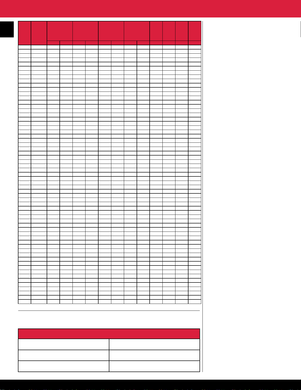
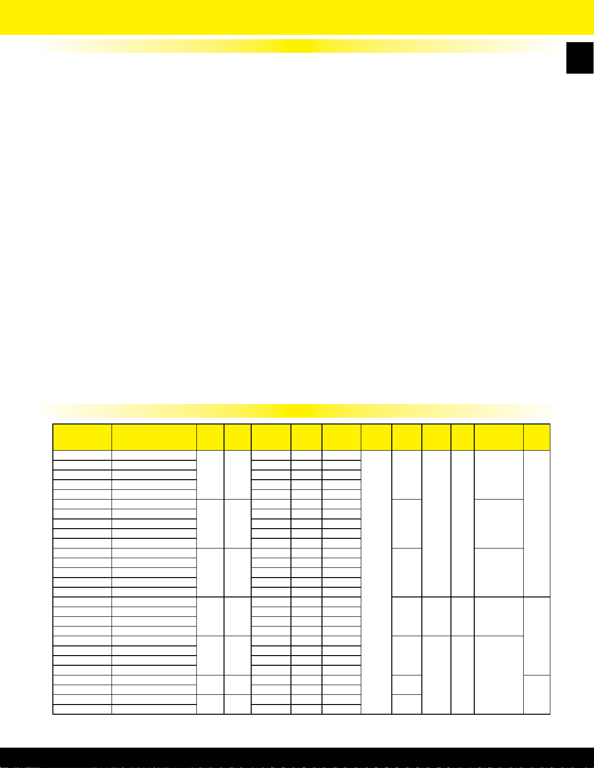
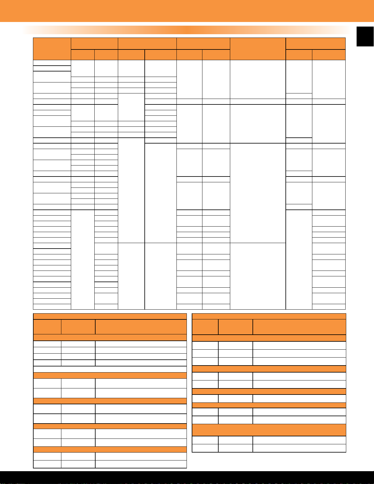
Amperage Chart & Electric Heat Products Limited Warranty
277
440
2
K.W
B.T.U.H.
Rating
00.5 1,706 2.4 1.4 2.3 1.3 2.2 1.3 2.1 1.2 1.8 0.6 0.6 0.5
01.0 3,413 4.8 2.8 4.5 2.6 4.3 2.5 4.2 2.4 3.6 1.3 1.2 1.0
02.0 6,826 9.6 5.5 9.1 5.2 8.7 5.0 8.3 4.8 7.2 2.6 2.4 2.1
03.0 10,239 14.4 8.3 13.6 7.9 13.0 7.5 12.5 7.2 10.8 3.9 3.6 3.1
04.0 13,652 19.2 11.1 18.2 10.4 17.5 10.1 16.6 9.6 14.4 5.2 4.8 4.2
05.0 17,065 24.0 13.8 22.7 13.1 21.7 12.6 20.8 12.0 18.1 6.6 6.0 5.2
06.0 20,478 28.8 16.6 27.3 15.7 26.1 15.1 25.0 14.4 21.7 7.9 7.2 6.3
07.0 23,891 33.6 19.4 31.8 18.4 30.4 17.6 29.1 16.8 25.3 9.2 8.4 7.3
08.0 27,304 38.5 22.2 36.4 20.9 34.9 20.1 33.3 19.2 28.9 10.5 9.6 8.4
09.0 30,717 42.8 24.9 40.9 23.3 39.1 22.6 37.7 21.4 32.5 11.8 10.8 9.5
10.0 34,130 48.1 27.4 45.4 26.2 43.5 25.1 41.7 24.0 36.1 13.2 12.0 10.5
11.0 37,543 52.9 30.5 50.0 28.6 47.8 27.6 45.8 26.4 39.7 14.5 13.2 11.6
12.0 40,956 57.7 33.2 54.5 31.5 52.1 30.2 50.0 28.6 43.3 15.8 14.4 12.6
13.0 44,369 62.5 36.0 59.1 34.1 56.9 32.7 54.2 31.3 46.9 17.1 15.6 13.7
14.0 47,782 67.3 38.8 63.6 36.7 60.9 35.2 58.3 33.7 50.5 18.4 16.8 14.7
15.0 51,195 72.1 41.5 68.2 39.1 65.2 37.7 62.5 35.1 54.2 19.8 18.0 15.8
16.0 54,608 76.9 44.3 72.7 41.9 69.6 40.2 66.7 38.5 57.8 21.1 19.2 16.9
17.0 58,021 81.7 47.1 77.3 44.3 73.9 42.7 70.8 40.9 61.4 22.4 20.4 17.9
18.0 61,434 86.5 49.8 81.8 47.2 78.3 45.2 75.0 43.3 65.0 23.7 21.6 19.0
19.0 64,847 91.3 52.6 86.4 49.6 82.6 47.7 79.2 45.7 68.6 25.1 22.8 20.0
20.0 68,260 96.1 55.1 90.9 52.5 86.9 50.3 83.3 48.1 72.2 26.4 24.0 21.1
21.0 71,673 100.0 58.2 95.6 55.1 91.3 52.9 87.5 50.5 75.8 27.7 25.2 22.1
22.0 75,086 105.8 60.9 100.0 57.7 95.7 55.3 91.7 52.9 79.4 29.0 26.4 23.1
23.0 78,499 110.6 63.7 14.5 60.4 100.0 57.9 95.8 55.3 83.0 30.3 27.6 24.3
24.0 81,912 115.4 66.5 109.1 62.9 104.3 60.3 100.0 57.7 86.6 31.7 28.8 25.3
25.0
85,325 120.2 69.2 113.6 65.3 108.6 62.8 104.1 60.1 90.3 33.0 30.1 26.4
26.0 88,738 125.0 72.0 118.2 68.3 113.0 65.3 108.3 62.5 93.9 34.3 31.3 27.4
27.0 92,151 129.8 74.8 122.7 70.9 117.4 67.8 112.5 64.7 97.5 35.6 32.5 28.5
28.0 95,564 134.6 77.2 128.2 73.5 121.7 70.3 116.6 67.3 101.1 36.9 33.7 29.5
29.0 98,977 139.4 80.3 131.8 76.0 126.0 72.9 120.8 69.7 104.7 38.3 34.9 30.6
30.0 102,390 144.2 83.1 136.4 78.7 130.4 75.4 125.0 72.1 108.3 39.6 36.1 31.7
31.0 105,803 149.0 85.9 140.9 81.3 134.7 77.9 129.2 74.5 111 .9 40.9 37.3 32.7
32.0 109,216 153.8 88.7 145.4 83.9 139.0 80.4 133.4 76.9 115.5 42.2 38.5 33.8
33.0 112,629 158.6 91.5 149.9 86.5 143.3 82.9 137.6 79.3 119.1 43.5 39.7 34.8
34.0 116,042 163.4 94.3 154.4 89.1 147.6 85.4 141.8 81.7 112.7 44.8 40.9 35.9
35.0 119,455 168.2 97.1 158.9 91.7 151.9 87.9 146.0 84.1 126.4 46.1 42.1 36.9
36.0 122,868 173.0 99.9 163.4 94.3 156.2 90.4 150.2 86.5 130.0 47.4 43.3 38.0
37.0 126,281 177.8 102.7 167.9 96.9 160.5 92.9 154.4 88.9 133.6 48.7 44.5 39.0
38.0 129,694 182.6 105.5 172.4 99.5 164.8 95.4 158.6 91.3 137.2 50.0 45.7 40.1
39.0 133,107 187.4 108.3 176.9 102.1 169.1 97.9 162.8 93.7 140.7 51.3 46.9 41.1
40.0 136,520 192.2 111 .1 181.4 104.7 173.4 100.4 167.0 96.1 144.4 52.6 48.1 42.2
41.0 139,933 197.0 113.9 185.9 107.3 177.7 102.9 171.2 98.5 148.0 53.9 49.3 43.2
42.0 143,346 201.8 116.7 190.4 109.9 182.0 105.4 175.4 100.9 151.6 55.2 50.6 44.3
43.0 146,759 206.6 119.5 194.9 112.5 186.3 107.9 179.6 103.3 155.2 56.5 51.8 45.3
44.0 150,172 211.4 122.3 199.4 115.1 190.6 110.4 183.8 105.7 158.8 57.8 53.0 46.4
45.0 153,585 216.2 125.1 203.9 117.7 194.9 112.9 188.0 108.1 162.5 59.1 54.2 47.4
46.0 156,998 221.0 127.9 208.4 120.3 199.2 115.4 192.2 110.5 166.1 60.4 55.4 48.5
47.0 160,411 225.8 130.7 212.9 122.9 203.5 117.9 196.4 112.9 169.7 61.7 56.6 49.5
48.0 163,824 230.6 133.5 217.4 125.5 207.8 120.4 200.6 115.3 173.3 63.0 57.8 50.6
49.0 167,237 235.4 136.3 221.9 128.1 212.1 122.9 204.8 117.7 176.9 64.3 59.0 51.6
50.0 170,650 240.2 139.1 226.4 130.7 216.4 125.4 209.0 120.1 180.5 65.6 60.2 52.7
51.0 174,063 245.0 141.9 230.9 133.3 220.7 127.9 213.2 122.5 184.1 66.9 61.4 53.7
52.0 177,476 249.8 144.7 235.4 135.9 225.0 130.4 217.4 124.9 187.7 68.2 62.6 54.8
53.0 180,889 254.6 147.5 239.9 138.5 229.3 132.9 221.6
54.0 184,302 259.4 150.3 244.4 141.1 233.6 135.4 225.8 129.7 194.9 70.8 65.0 56.9
55.0 187,715 264.2 153.1 248.9 143.7 237.9 137.9 230.0 132.1 198.6 72.2 66.2 57.9
56.0 191,128 269.0 155.9 253.4 146.3 242.2 140.4 234.2 134.5 202.2 73.5 67.4 58.8
57.0 194,541 273.8 158.7 257.9 148.9 246.5 142.9 238.4 136.9 205.8 74.9 68.6 59.9
58.0 197,954 278.6 161.5 262.4 151.5 250.8 145.4 242.6 139.3 209.4 76.2 69.8 60.9
59.0 201,367 283.4 164.3 266.9 154.1 255.1 147.9 246.8 141.7 213.0 77.5 71.0 62.3
60.0 204,780 288.2 167.1 271.4 156.7 259.4 150.4 251.0 144.1 216.6 78.8 72.2 63.0
208 Volt
AMP Rating
1 PH 3 PH 1 PH 3 PH 1 PH 3 PH 1 PH 3 PH 1 PH 3 PH 3 PH 3 PH
220 Volt
AMP Rating
230 Volt
AMP Rating
240 Volt
AMP Rating
Volt
AMP
Rating
Rating
127.3 191.3 69.5 63.8 55.8
Volt
AMP
480
Volt
AMP
Rating
Note: All custom built products are subject to 100% cancellation/restock charges.
In addition to the Limited Warranty stated to the right covering general products, TPI Corporation
extends this warranty on the following listed products, which are warranted to the original
consumer from the original date of purchase for the total time periods indicated herein below:
Heat Products
Elements in 2900 Series Baseboard 10 Years
All Other Heating Products 1 Year
Thermostats & Controls 2 Years
TPI Corporation provides a limited warranty
550
of materials and workmanship for a period
Volt
of (i) ten (10) years for elements in 2900
AMP
Series baseboard heaters, (ii) two (2) years
Rating
for Thermostats and Controls, (iii) ve (5)
years on HD and HDH series fans, (iv) three
(3) years on UHP and IHP series fans, (v)
and twelve (12) months for all other products,
with the warranty period commencing on the
original date of purchase. The TPI warranty
is limited to materials manufactured and work
performed by TPI Corporation, and does not
include damage or failure caused by acts of
God, abuse, misuse, connected to or placed
on other than rated voltage, abnormal usage,
faulty installation, failure to follow suggested
maintenance procedures enclosed with
the product, improper maintenance or any
repairs other than those provided by an
authorized TPI Corporation service center.
For the name of your nearest authorized TPI
Corporation service center, please write to
TPI Corporation, P.O. Box 4973, Johnson
City, Tennessee, 37602 or call
1-800-682-3398.
During the warranty period, TPI Corporation
will, at its sole option, repair or replace any
defective parts or products returned, freight
prepaid, to the TPI Corporation factory or
such other location as TPI Corporation may
designate. No parts or products will be
accepted for repair or replacement without
prior authorization from TPI Corporation
and a return merchandise authority (RMA)
number issued by TPI Corporation. Returned
products must be packaged carefully and
TPI Corporation shall not be responsible for
damage in transit. When returning parts,
the owner must provide the model number
of the product and nature of difculty being
experienced.
This warranty does not obligate TPI
Corporation to bear the cost of labor in
replacing any assembly, unit or component
part thereof, nor does TPI Corporation
assume any liability for secondary charges,
expenses for installing or removal, freight or
damages. There will be charges rendered
for product repairs made after the warranty
period has expired. Proof of purchase,
including date, must accompany request for
in-warranty service. This warranty gives you
specic legal rights and you may have other
rights, which may vary, from state to state.
Except for the limited warranty provided in the
foregoing paragraph, all parts and products
sold by TPI Corporation are sold ‘as is’,
‘where is’, and without any other warranty of
any kind or nature, whether express, implied,
or statutory and including, without limitation,
any implied warranty of specic performance
or merchantability.
Under no circumstances, even with respect
to claims covered by the foregoing warranty,
will TPI Corporation be responsible for any
incidental, consequential, special, or punitive
damages of any kind or nature arising from
or related to the parts or products sold by TPI
Corporation.
In any event, TPI Corporation’s maximum
liability shall not in any case exceed the
purchase price for the part or product claimed
to be defective.
You hereby expressly agree to waive any
and all rights to a trial by jury with respect to
any product manufactured or supplied by TPI
Corporation.
Page 4
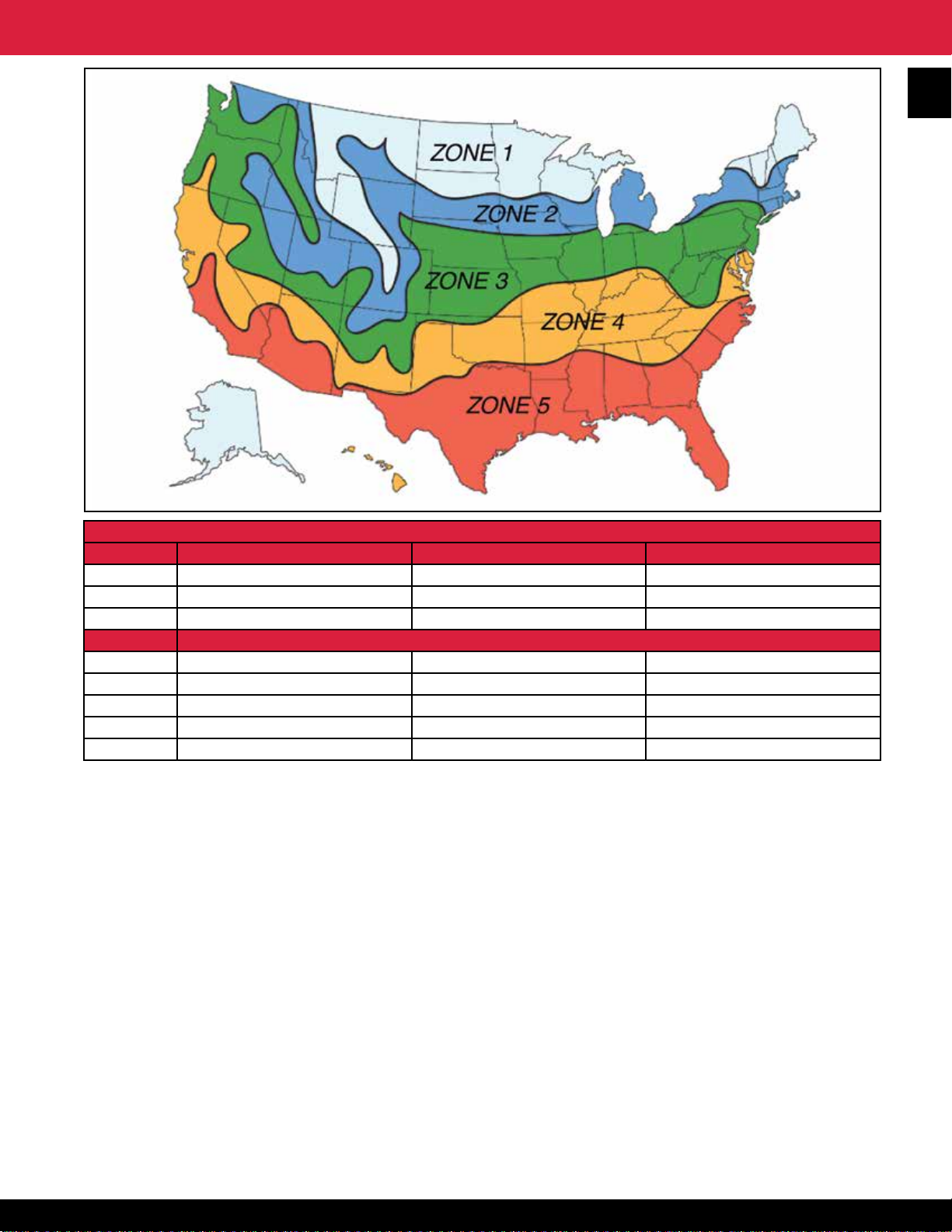
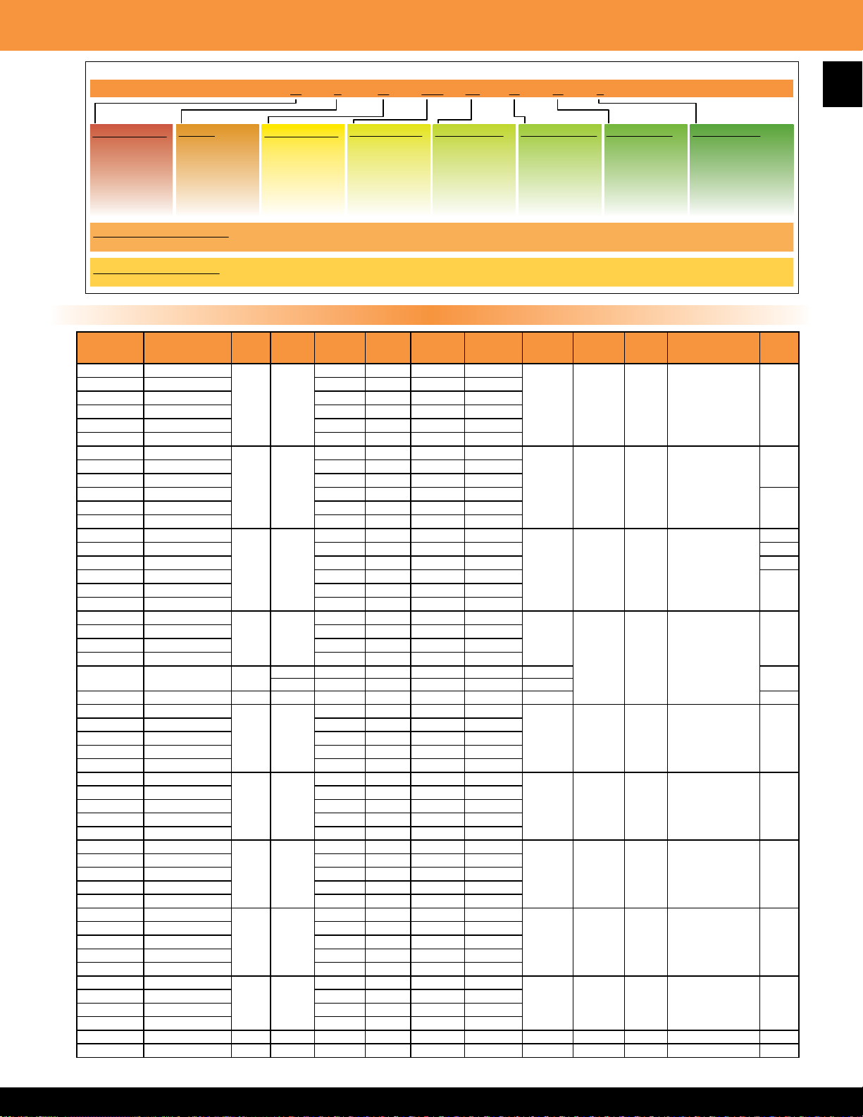
Electric Heat Comfort Zones
3
INSULATION
R-VALUE Recommended FHA Standard Minimum: Not Recommended
Ceiling *R-24 *R-19 *R-11
Walls R-13 11 R-7
Floor R-24 11 ----
ZONE APPROXIMATE WATTAGE NEED PER SQUARE FOOT
1 8.6 10.0 14.6
2 7.7 9.0 13.1
3 7.1 8.2 12.0
4 6.4 7.4 10.8
5 6.0 7.0 10.2
*”R”values are industry standards for insulation effectiveness. Ask company representative for assistance if you do not know “R” for your present structure insulation.
Baseboard or wall mount style? Recessed or surface type? It’s easy to select the heater that’s right for you.
1. Measure the size of the room(s) or area you intend to heat for square footage.
You will need the length times the width to get this calculation.
2. Find your location on the map above. This determines your basic heating zone.
3. The chart shown below the map lists insulation values based on the effectiveness of the insulation presently in your home.
Find your heating zone on the chart and the approximate wattage per square foot you will need.
4. Multiply the total number of square feet you intend to heat by the approximate wattage per square foot you just obtained.
This will determine your total heating requirement in watts for the room.
How Much Heat is Right For You?
Figures are based on 15% total window and door openings in outside walls, and 3/4 total home air changes per hour.
Typical frame-type construction with unheated basement or unventilated crawl space.
If you do not have storm doors and windows, add 30% to the watts per square foot (multiply by 1.3).
That’s all there is to it! Now choose the heater with a wattage equal to what you need. Your nal selection will, of course, depend on available wall space, window placement, ect.
Sample Calculation:
Example = 10’ x 12’ room in Zone 3 with FHA standard insulation
1. Determine room square footage: 10’ x 12’ = 120 sq. ft.
2. Zone 3 with FHA standard insulation requires 8.2 watts per sq. ft.
3. Multiply square footage of room to be heated by the approximate wattage per square foot required.
120 sq. ft x 8.2 watts = 984 watts required.
From this calculation it can be reasoned that a 1000 watt heater would be required.
Page 5
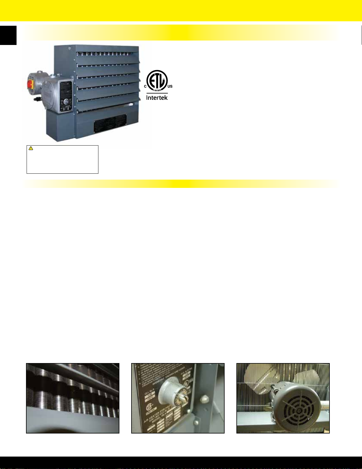
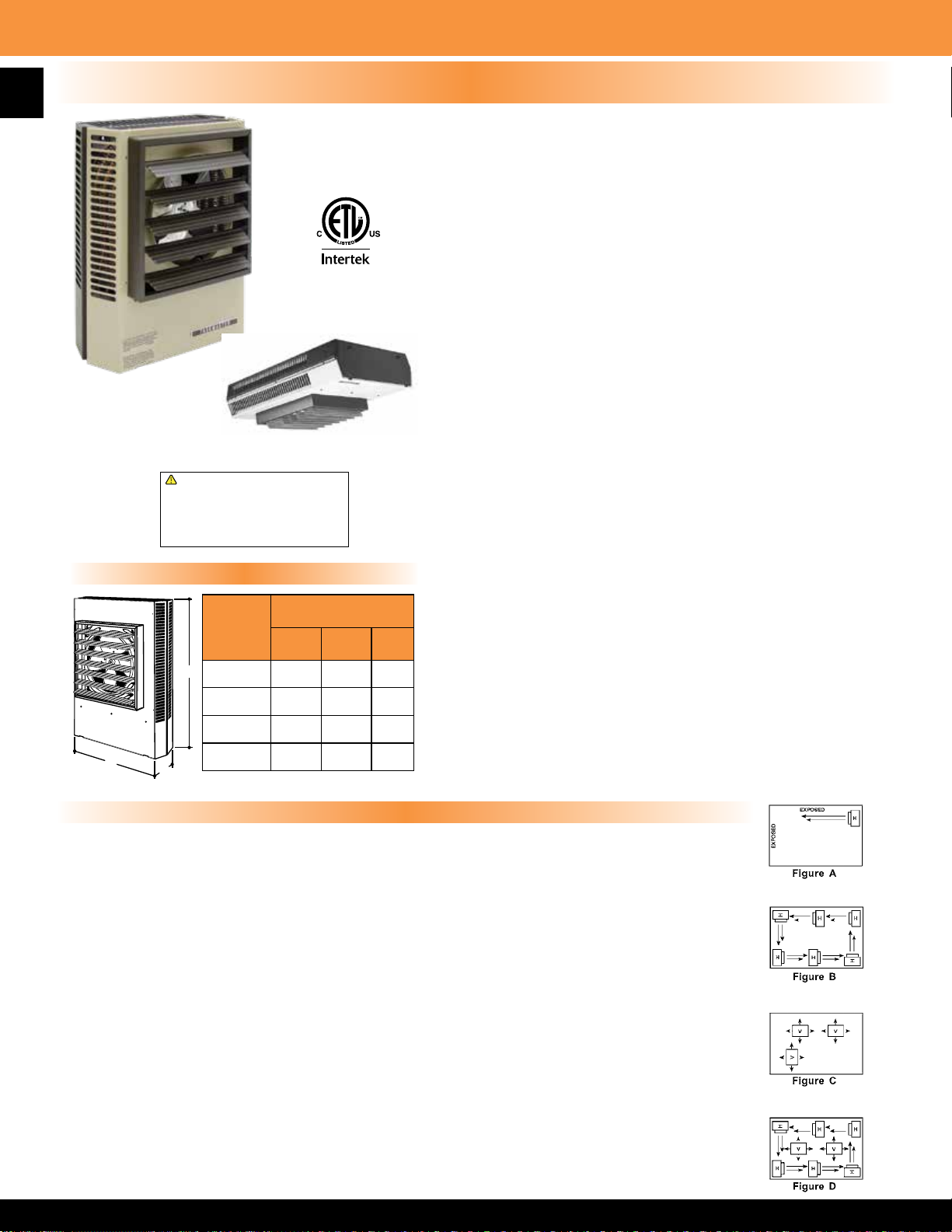
HLA Series Hazardous Location Fan Forced Unit Heater
FAN-FORCED SUSPENDED UNIT HEATERS 3-25 KW FOR T-3B CLASS I, GROUP C & D,
4
!
WARNING: This product can expose you
to chemicals including nickel which is known
to the State of California to cause cancer,
and chromium, which is known to the State
of California to cause birth defects and/or
reproductive harm. For more information go
to www.P65Warnings.ca.gov.
Heat Exchanger and Elements:
Heavy walled, painted carbon steel with aluminum ns liquid heat exchanger, liquid lled with three-immersion type copper
sheathed elements. The elements shall have the highest quality nickel-chromium resistance wire encased in a magnesium oxide
dielectric and be hermetically sealed into the heat exchanger core. The heat transfer uid is Ethylene-glycol solution for operation
to -49 degrees F (– 45 degrees C). Stainless steel and aluminum pressure relief valve for overpressure.
DIVISION 1 & 2 AND CLASS II, GROUPS E, F & G, DIVISIONS 1 & 2.
• Designed for rugged industrial applications in hazardous locations
where the possibility of explosion or re exists due to the presence of
certain ammable gases, vapors, powdered metals or dust
• Permanently sealed, liquid to air, nned tube heat exchanger core
• Ethylene Glycol to water mixture used as a heat transfer uid in the
heater core, providing -45° C. (-49° F) freeze damage protection
• High-performance electric motor driven fan blows air across nned
tubes to effect uniform heat transfer and area heat distribution
• Manual Reset capillary type limit provides high temperature regulation
and is rated for 6,000 cycles of service
• Stainless steel and aluminum pressure relief valve for overpressure
• A back-up contactor is included for additional protection
• 14 gauge steel cabinet powder coated epoxy paint nish contains
Shown with optional
pilot light and
disconnect switch
heater core, motor, and fan assembly
• Narrow gap safety fan guard shields all moving parts
• Adjustable louvers allow directional control of air
• Copper conductor wires enclosed in rigid metal conduits carry all
electrical power
• Box lugs furnished for eld connections within approved enclosure
• Made in U.S.A.
Product Specications
Thermal Cutout High Limit Protection and Optional Pilot Light:
The capillary type manual reset thermal cutout shall be rated for 6000 cycles of service and mounted in the liquid lled heat
exchanger. An optional pilot light to indicate manual reset tripped, if safe operating temperatures are exceeded, is located on
control enclosure.
Motor:
The motor shall be a permanent split capacitor type, permanently lubricated, ball bearing type. The motor shall be rated for
hazardous location and operate at rated voltage of heater, 60 Hz, 1725 RPM.
Control Enclosure:
All controls shall be factory installed and wired in a hazardous location enclosure. Contactors and back-up contactors are heavy
duty type and break all ungrounded conductors and be rated for 100,000 cycles at full load. Standard 24-Volt control circuit shall
be supplied by internal class II transformer. An optional factory wired integral thermostat or standard terminal block for eld wiring
to optional remote wall thermostat are wired in control panel. No fan delay relay.
Disconnect Switch:
Factory mounted and wired hazardous location disconnect switch is available as optional accessory.
Cabinet With Adjustable Louvers:
The Cabinet shall be 14 gauge, cold rolled steel with powder coated epoxy nish. Plated fan guards with less than 1/4 inch
spacing to cover motor and fan shall conform to OSHA Requirements.
Note: Before selecting a hazardous location electric heater refer to Article 500 or other applicable standard referenced in the
National Electric Code.
Liquid-to-air heat exchanger Optional built-in thermostat Hazardous Location Rated Motor
Page 6
HLA Series Hazardous Location Fan Forced Unit Heater
Rating Denitions
CLASS I: Equipment does not have surface operating temperature in excess of the ignition temperature of the specic gas or vapor.
Application Examples:
• Offshore and land based drilling rigs, petroleum exploration and testing facilities
• Petroleum reneries, gasoline storage and dispensing areas
• Industrial rms that use ammable liquids in dip tanks for parts cleaning or other operations
• Petrochemical companies that manufacture chemicals from gas or oil
• Dry cleaning facilities where vapors from cleaning uids may be present
• Aircraft hangers and fuel servicing areas
• Utility gas plants and operations involving storage and handling of liqueed petroleum or natural gas
GROUP C: Atmospheres such as but not limited to acetaldehyde, allyl alcohol, hydrogen sulde, ethylene, carbon monoxide, or other gases or
vapors of equivalent hazard.
GROUP D: Atmospheres such as but not limited to acetone, alcohol, gasoline, lacquer solvent vapors, natural gas, propane or other gases or
vapors of equivalent hazard.
CLASS II: Equipment does not have surface temperature greater than the ignition temperature of the specied dust.
Application Examples:
• Coal preparation plants and other carbon handling or processing areas
• Grain elevators, our and feed mills
• Plants which manufacture, use or store Magnesium or Aluminum powders
• Plants that have chemical or metallurgical processes.
• Producers of starch products or candy
• Spice grinding plants, sugar plants and cocoa plants
GROUP E: Atmosphere containing combustible metal dust regardless of resistivity, or other combustible dust of similar hazard characteristics
having resistivity of less than 105 OHM - Centimeter.
5
GROUP F: Atmosphere containing carbon black, charcoal, coal or coke dust.
GROUP G: Atmospheres containing combustible dust having resistivity of 105 OHM-Centimeter or greater.
DIVISION I: A location in which ignitable concentrations of ammable material exist under normal operating conditions.
DIVISION II: Locations in which ammable materials will normally be conned within closed containers and escape only in the case of accidental
rupture, breakdown or during maintenance operations. Any equipment approved for Division I is automatically also approved for Division II.
Standard Hazardous Location Models
MFG CATALOG
NUMBER
07343502 HLA 12-208160-3.0-24
07340002 HLA 12-208360-3.0-24 208 3 9.8
07340102 HLA 12-240160-3.0-24 240 1 14.8
07340202 HLA 12-240360-3.0-24 240 3 8.6
07340302 HLA 12-480360-3.0-24 480 3 4.3
07343602 HLA 12-208160-5.0-24
07340502 HLA 12-208360-5.0-24 208 3 15.4
07340602 HLA 12-240160-5.0-24 240 1 23.1
07340702 HLA 12-240360-5.0-24 240 3 13.4
07340802 HLA 12-480360-5.0-24 480 3 6.7
07343702 HLA 12-208160-7.5-24
07341002 HLA 12-208360-7.5-24 208 3 22.3
07341102 HLA 12-240160-7.5-24 240 1 33.6
07341202 HLA 12-240360-7.5-24 240 3 19.4
07341302 HLA 12-480360-7.5-24 480 3 9.7
07341502 HLA 16-208360-10.0-24
07341602 HLA 16-240160-10.0-24 240 1 44
07341702 HLA 16-240360-10.0-24 240 3 25.5
07341802 HLA 16-480360-10.0-24 480 3 12.7
07342002 HLA 20-208360-15.0-24
07342102 HLA 20-240360-15.0-24 240 3 38.1
07342202 HLA 20-480360-15.0-24 480 3 19
07342302 HLA 20-600360-15.0-24 600 3 15.2
07342402 HLA 20-480360-20.0-24
07342502 HLA 20-600360-20.0-24 600 3 20
07342602 HLA 20-480360-25.0-24
07342702 HLA 20-600360-25.0-24 600 3 24.9
Note: Products listed in this section are custom built and subject to 100% cancellation/restock charges.
MFG MODEL
NUMBER
KW BTUs VOLTS PH AMPS
208 1 16.3
3 10250
208 1 26
5 17100
208 1 38
7.5 25600
208 3 29.3
10 34150
208 3 43.5
15 51200
20 68300
25 85400
480 3 25.1
480 3 31.1
Control
Voltage
24
Temp
Rise °F
16.5
27.6 8’
41.4 8’
21.7 40’ 1500 10’
19.2
26.2
32.8
Air
CFM
Throw
24’ 580
43’ 2450 13’
Mounting Ht.
Recom’d
WT.
(LBS)
8’
167
193
225
Page 7
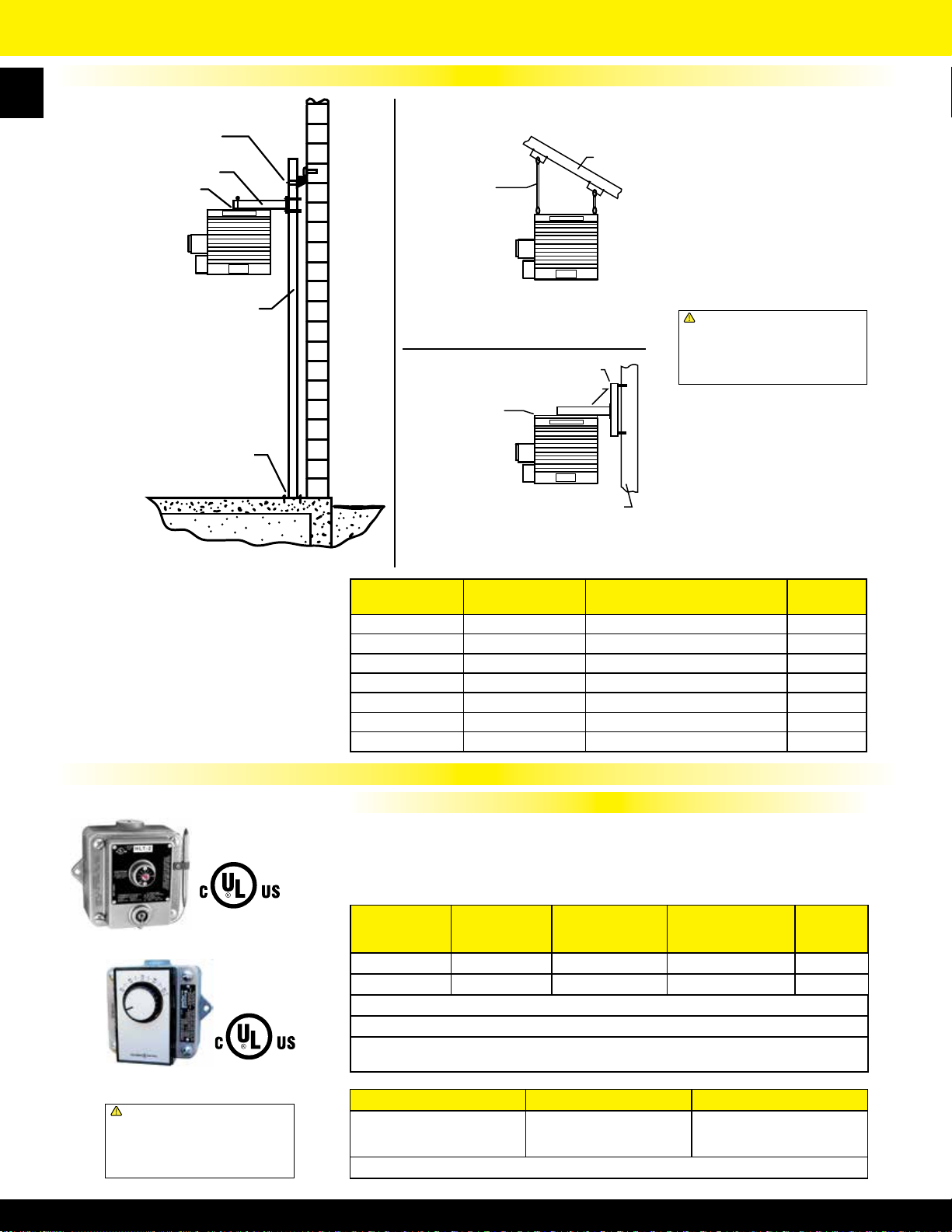
6
Mounting arm assembly
Mounting Arm Assembly
Attachment Assembly
Attachment assembly
HLA Series Hazardous Location Fan Forced Unit Heater
Mounting Bracket Kits
Column Stabilizing
Column stabilizing
components
Components
1/2” Pipe
1/2” Pipe
(Not Supplied)
(Not Supplied)
Roof or overhead
Roof or Overhead
structure
Structure
3 1⁄2” Schedule 40 (Pipe)
3 1/2” Schedule 40 (Pipe)
(Not Supplied)
(Not Supplied)
Base assembly
Base Assembly
HLPM Pipe Mounting Kit
Particularly useful in buildings with
insufcient strength to use other
types of mounts. Requires 3 1⁄2’’ pipe
(4’’ O.D. - not supplied).
HLHM Hanging Mounting Kit
Simple and economical if adequate
overhead structure exists. Requires 1/2’’
pipe, cut and threaded (not supplied)
Wall Bracket
Wall bracket
Mounting Arm
Attachment
Attachment
Assembly
assembly
Mounting arm
Wall or Structure
Wall or structure
!
WARNING: This product can expose you
to chemicals including nickel which is known
to the State of California to cause cancer,
and chromium, which is known to the State
of California to cause birth defects and/or
reproductive harm. For more information go
to www.P65Warnings.ca.gov.
HLWM Wall Mounting Kit
Ideal for use in buildings that have
substantial walls. Arm only can also
be bolted directly to structural steel.
MFG CATALOG
NUMBER
MFG MODEL
NUMBER
USE WITH HEATERS
07342802 HLPM37 3.0 kW - 7.5 kW 37
07342902 HLPM10 10.0 kW 38
07343002 HLPM1525 15.0 kW - 25.0 kW 40
07343102 HLHM ALL 5
07343202 HLWM37 3.0 kW - 7.5 kW 27
07343302 HLWM10 10.0 kW 28
07343402 HLWM1525 15.0 kW - 25.0 kW 29
WT.
(LBS)
EPET Series and HLT Series Hazardous Location Thermostats For Single Phase
HLT Series
!
WARNING: This product can expose you
to chemicals including nickel which is known
to the State of California to cause cancer,
and chromium, which is known to the State
of California to cause birth defects and/or
reproductive harm. For more information go
to www.P65Warnings.ca.gov.
Features
• Celsius and Fahrenheit temperature scale
• Bi-Metal or capillary sensor
• Snap action switch
• Casting tapped top and bottom for 3⁄4” conduit
• 1⁄2” thick cast aluminum housing
MFG CATALOG
NUMBER
MFG MODEL
NUMBER
DESCRIPTION LOAD RATINGS RANGE
05381002 EPETD8S SPDT - Bi-Metal 22A @120-277VAC 50-90
05231502 HLT-1 SPDT - Capillary 22A @120-277VAC 40-110
Master ctn: 4 pcs, 24 llbs (varies slightly by model), 16” x 14.5” x 6”
EPET Series incorporate plastic knob & Bi-Metal Sensor housing.
HLT Series incorporates screwdriver temperature adjustment slot and all metal housing.
External bulb and capillary sensor.
Motor Rating Rating Rated*
(full load)
1
⁄2 HP at 250V
1
22A at 125-277VAC;
125 VA at 24VAC
*Thermostat is not rated for use in Group B environments.
• All EPET optional thermostats
manufactured with anti-static plastic
• Dimension 5.75” x 6.375” x 5.57”
• Made in U.S.A.
Class I Group C & D,
Class II Group E, F, G
o
F
o
F
Page 8
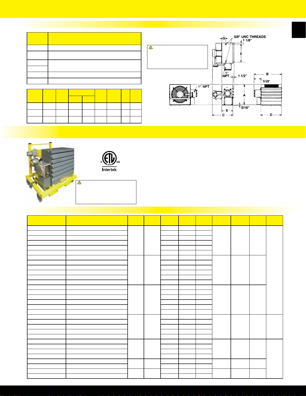
HLA Series Hazardous Location Fan Forced Unit Heater
Factory Installed Accessories & Physical Dimensions
Top View
SUFFIX DESCRIPTION
!
T In-Built single pole thermostat 40° - 100° F
120
208
240
Control transformer w/ primary fusing
(Delete 24 sufx - add 120)
208/240V Control available on 208/240V units
(Delete 24 sufx and add 208 OR 240)
D Disconnect Switch
P Pilot Light
WARNING: This product can expose you
to chemicals including nickel which is known
to the State of California to cause cancer,
and chromium, which is known to the State
of California to cause birth defects and/or
reproductive harm. For more information go
to www.P65Warnings.ca.gov.
7
Front View
MFG
MODEL
HLA 12 17
HLA 16 20
HLA 20 24
A B
3
⁄4 22 3⁄8 19 3⁄4 20 5⁄8 16 1⁄4 10 1⁄2 14 3
3
⁄4 26 3⁄8 20 3⁄4 21 5⁄8 20 1⁄4 11 1⁄2 18 4
3
⁄4 30 3⁄8 22 1⁄2 N/A 24 1⁄4 12 1⁄2 22 4 1⁄2
C
3 ph. 1 ph.
D E F G
Rear View
PHLA Series Portable Hazardous Location Fan Forced Unit Heater
• 3.0 through 25 KW rating
• 208, 240, 480, 600 Volt available in selected capacities
• Cart has anti-static wheels to reduce the risk of static discharge
• Wheeled cart allows for easy maneuverability
• Cart has integrated fork-lift channels to provide ease
of lifting on to ramps or trucks
• Excellent for providing seasonal heating in hazardous environments
• All units have disconnect switch, pilot light, and thermostat - standard
!
WARNING: This product can expose you
to chemicals including nickel which is known
to the State of California to cause cancer,
and chromium, which is known to the State
of California to cause birth defects and/or
reproductive harm. For more information go
to www.P65Warnings.ca.gov.
Standard Portable Hazardous Location Models
MFG CATALOG
NUMBER
07393402 PHLA12-208160-3.0-24-TDP
07393302 PHLA12-208360-3.0-24-TDP 208 3 9.8
07393202 PHLA12-240160-3.0-24-TDP 240 1 14.8
07393102 PHLA12-240360-3.0-24-TDP 240 3 8.6
07393002 PHLA12-480360-3.0-24-TDP 480 3 4.3
07394302 PHLA12-600360-3.0-24-TDP 600 3 3.5
07392902 PHLA12-208160-5.0-24-TDP
07392802 PHLA12-208360-5.0-24-TDP 208 3 15.4
07392702 PHLA12-240160-5.0-24-TDP 240 1 23.1
07392602 PHLA12-240360-5.0-24-TDP 240 3 13.4
07392502 PHLA12-480360-5.0-24-TDP 480 3 6.7
07394202 PHLA12-600360-5.0-24-TDP 600 3 5.4
07392402 PHLA12-208160-7.5-24-TDP
07392302 PHLA12-208360-7.5-24-TDP 208 3 22.3
07392202 PHLA12-240160-7.5-24-TDP 240 1 33.6
07392102 PHLA12-240360-7.5-24-TDP 240 3 19.4
07392002 PHLA12-480360-7.5-24-TDP 480 3 9.7
07394102 PHLA12-600360-7.5-24-TDP 600 3 7.8
07391902 PHLA16-208360-10.0-24-TDP
07391802 PHLA16-240160-10.0-24-TDP 240 1 44
07391702 PHLA16-240360-10.0-24-TDP 240 3 25.5
07391602 PHLA16-480360-10.0-24-TDP 480 3 12.7
07394002 PHLA16-600360-10.0-24-TDP 600 3 10.2
07391502 PHLA20-208360-15.0-24-TDP
07391402 PHLA20-240360-15.0-24-TDP 240 3 38.1
07391302 PHLA20-480360-15.0-24-TDP 480 3 19
07393902 PHLA20-600360-15.0-24-TDP 600 3 15.2
07391202 PHLA20-480360-20.0-24-TDP
07393802 PHLA20-600360-20.0-24-TDP 600 3 20
07391102 PHLA20-480360-25.0-24-TDP
07393702 PHLA20-600360-25.0-24-TDP 600 3 24.9
MFG MODEL
NUMBER
• 24 Volt control, transformer, and contactor in NEMA 7 enclosure
• Durable epoxy coating on heater housing
• Hazardous location unit mounted male / female plug
• Adjustable louvers; manual reset
• Made in U.S.A.
KW BTUs VOLTS PH AMPS
208 1 16.3
3 10,250
208 1 26
5 17,100
208 1 38
7.5 25,600
208 3 29.3
10 34,150
208 3 43.5
15 51,200
20 68,300
25 85,400
480 3 25.1
480 3 31.1
Side View
TEMP
RISE F
16.5 24’ 580
27.6 24’ 580
41.4 24’ 580
21.7 40’ 1500 305
19.2 43’ 2450
26.2 43’ 2450
32.8 43’ 2450
AIR
THROW
CFM
WT.
(LBS)
260
350
Page 9
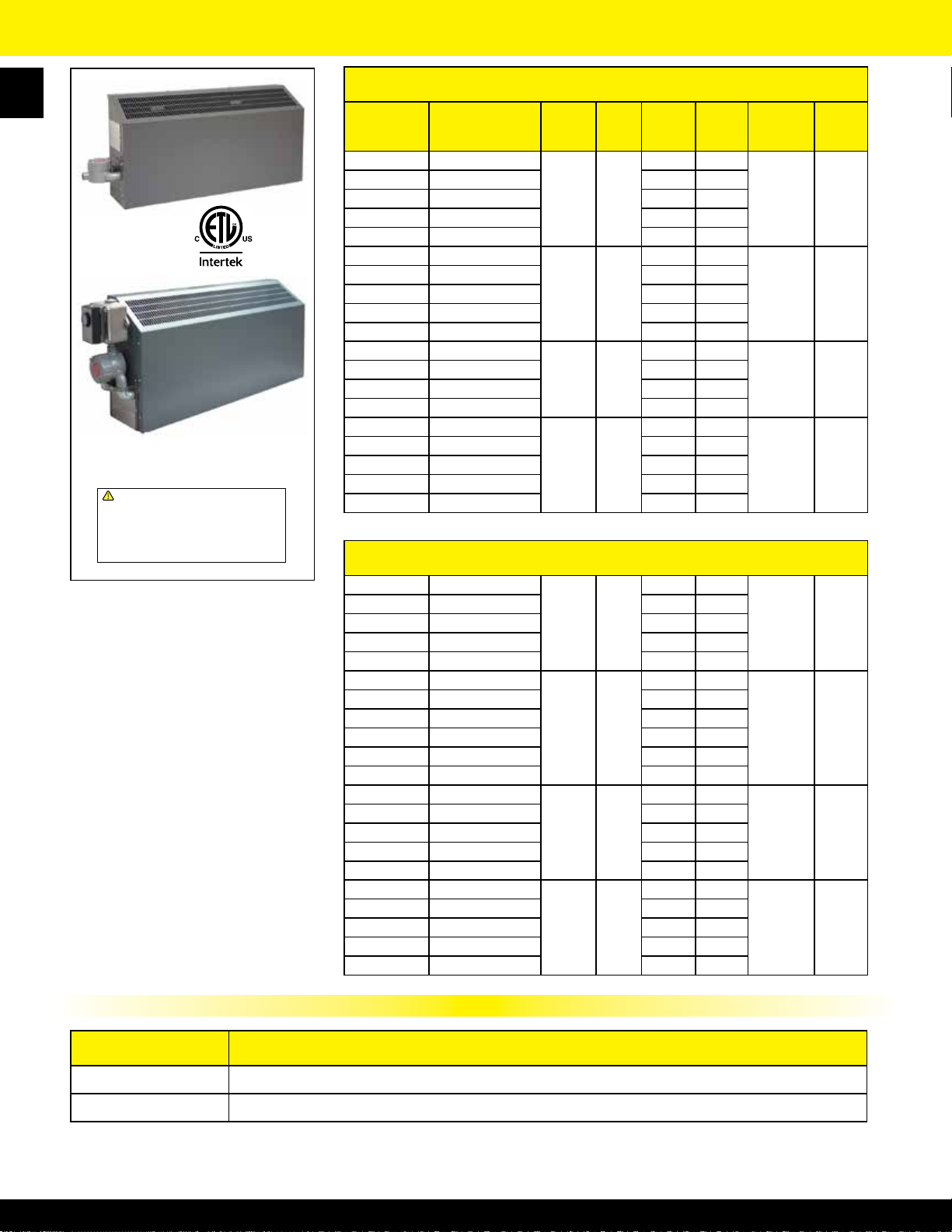
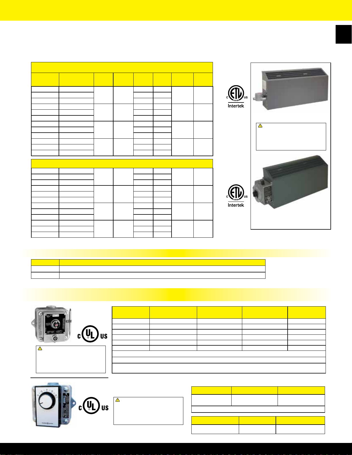
FEP Series Single Phase Hazardous Location Wall Convector
8
Standard Unit
Unit with in-built EPET line voltage thermostat
(Sufx T1 or T2)
!
WARNING: This product can expose you
to chemicals including nickel which is known
to the State of California to cause cancer,
and chromium, which is known to the State
of California to cause birth defects and/or
reproductive harm. For more information go
to www.P65Warnings.ca.gov.
• Cabinet size 18” high, 9” wide
• Bottom In - Top Out air ow
• Wall mounting bracket supplied
• Units can not be operated in room ambients
exceeding 104°F (40°C)
• Heavy duty 16 gauge steel with gray epoxy
textured powder coated nish
• 9” minimum clearance from bottom of
heater to oor required
• Stainless steel cartridge element inserted
into Aluminum nned Copper sheath
• Standard unit (without EPET thermostat or
control section) is NEMA 4 rated
• Made in U.S.A.
Class 1, Group B, C & D Division 1 & 2 280° C / 536° F
T-2A SERIES SINGLE PHASE
MFG
CATALOG
NUMBER
04451402 FEP-1812-1RA
MFG
MODEL
NUMBER
WATTS BTUs VOLTS AMPS
120 15.0
04451502 FEP-1820-1RA 208 8.7
04451602 FEP-1824-1RA 240 7.5
1800 6143
04451702 FEP-1827-1RA 277 6.5
04451802 FEP-1848-1RA 480 3.8
04451902 FEP-3620-1RA
208 17.3
04452002 FEP-3624-1RA 240 15.0
04452102 FEP-3627-1RA 277 13.0
3600 12286
04452202 FEP-3648-1RA 480 7.5
04452302 FEP-3657-1RA 600 6.0
04452402 FEP-3820-1RA
04452502 FEP-3824-1RA 240 15.8
04452602 FEP-38271-RA 277 13.7
3800 12969
208 18.3
04452702 FEP-3848-1RA 480 7.9
04452802* FEP-7620-1RA
208 36.5
04452902* FEP-7624-1RA 240 31.7
04453002* FEP-7627-1RA 277 27.4
7600 25938
04453102 FEP-7648-1RA 480 15.8
04453202 FEP-7657-1RA 600 12.7
*Items may not be used with 22 Amp line voltage thermostat
T-3A SERIES SINGLE PHASE
Class 1, Group B, C & D Division 1 & 2 180° C / 356° F
04453302 FEP-0812-1RA
120 6.7
04453402 FEP-0820-1RA 208 3.8
04453502 FEP-0824-1RA 240 3.3
800 2730
04453602 FEP-0827-1RA 277 2.9
04453702 FEP-0848-1RA 480 1.7
04453802 FEP-1612-1RA
120 13.3
04453902 FEP-1620-1RA 208 7.7
04454002 FEP-1624-1RA 240 6.7
04454102 FEP-1627-1RA 277 5.8
1600 5460
04454202 FEP-1648-1RA 480 3.3
04454302 FEP-1657-1RA 600 2.7
04454402 FEP-1712-1RA
120 14.2
04454502 FEP-1720-1RA 208 8.2
04454602 FEP-1724-1RA 240 7.1
1700 5802
04454702 FEP-1727-1RA 277 6.1
04454802 FEP-1748-1RA 480 3.5
04454902 FEP-3420-1RA
208 16.3
04455002 FEP-3424-1RA 240 14.2
04455102 FEP-3427-1RA 277 12.3
3400 11604
04455202 FEP-3448-1RA 480 7.1
04455302 FEP-3457-1RA 600 5.7
CABINET
LENGTH
34” 50
34” 54
58” 80
58” 85
34” 50
34” 54
58” 80
58” 85
WT.
(LBS.)
Factory Installed Control Options
SUFFIX* DESCRIPTION
T1 EPETD8S single pole thermostat factory mounted to 120V
T2 EPETD8D double pole thermostat factory mounted to 120V - 277V units.
*Remove - RA sufx and add new sufx. Sufx “T” is 22 Amps maximum.
For 120V-480V thermostat, see page 6.
Note: All EPET / T1 / T2 optional thermostats manufactured with anti-static plastic
- 277V units. (50OF - 90OF)
(50OF - 90OF)
Page 10
FEP Series Three Phase Hazardous Location Wall Convector
• Cabinet size 18” high, 9” wide
• Bottom In - Top Out air ow
• Wall mounting bracket supplied
• Units can not be operated in
room ambients exceeding 104°F (40°C)
• Heavy duty 16 gauge steel with gray epoxy textured
powder coated nish
Class 1, Group B, C, & D Divisions 1 & 2 280° C / 536° F
MFG
CATALOG
NUMBER
04830502 FEP-1820-3RA
04862202 FEP-1848-3RA 480 2.2
04830702 FEP-3620-3RA
04862302 FEP-3648-3RA 480 4.3
04830902 FEP-3820-3RA
04862402 FEP-3848-3RA 480 4.6
04831102 FEP-7620-3RA
04862502 FEP-7648-3RA 480 9.2
04831302 FEP-0820-3RA
04862602 FEP-0848-3RA 480 0.9
04831502 FEP-1620-3RA
04862702 FEP-1648-3RA 480 1.9
04831702 FEP-1720-3RA
04862802 FEP-1748-3RA 480 2.0
04831902 FEP-3420-3RA
04862902 FEP-3448-3RA 480 4.1
MFG
MODEL
NUMBER
Class 1, Group B, C & D Division 1 & 2 180° C / 356° F
T-2A SERIES THREE PHASE
WATTS BTUs VOLTS AMPS
208 5.0
1800 6143
208 10.0
3600 12286
208 10.5
3800 12969
208 21.1
7600 25938
T-3A SERIES THREE PHASE
208 2.2
800 2730
208 4.4
1600 5460
208 4.7
1700 5802
208 9.4
3400 11604
• 9” minimum clearance from bottom of heater to oor required
• Stainless steel cartridge element inserted into Aluminum nned
Copper sheath
• Standard unit (without EPET thermostat or control section) is
NEMA 4 rated
• Made in U.S.A.
CABINET
LENGTH
34” 5004830602 FEP-1824-3RA 240 4.3
34” 5404830802 FEP-3624-3RA 240 8.7
58” 8004831002 FEP-3824-3RA 240 9.1
58” 8504831202 FEP-7624-3RA 240 18.3
34” 5004831402 FEP-0824-3RA 240 1.9
34” 5404831602 FEP-1624-3RA 240 3.8
58” 8004831802 FEP-1724-3RA 240 4.1
58” 8504832002 FEP-3424-3RA 240 8.2
WT.
(LBS.)
Standard Unit
!
WARNING: This product can expose you
to chemicals including nickel which is known
to the State of California to cause cancer,
and chromium, which is known to the State
of California to cause birth defects and/or
reproductive harm. For more information go
to www.P65Warnings.ca.gov.
Unit with optional control section containing
disconnect, pilot light, and thermostat
(Sufx C1-TDP)
Note: Controls mounted on the left side only
9
*T1 and T2 option not available on 3 phase models
Factory Installed Control Options
SUFFIX** DESCRIPTION
C1-TD Control section with transformer, 24V contactor, SP thermostat (40
C1-TDP
Control section with transformer, 24V contactor, SP thermostat (40OF - 100OF), disconnect switch & pilot light (all units)
Note: C1-TD and C1-TDP are only options available for 3 phase units.
O
F - 100OF) and disconnect switch (all units)
**Remove - RA sufx and
add new sufx (Not NEMA
washdown rated or rated
for Group B atmospheres)
Remote Mounted Hazardous Location Thermostats For Single Phase Power Only
HLT Series
!
WARNING: This product can expose you
to chemicals including nickel which is known
to the State of California to cause cancer,
and chromium, which is known to the State
of California to cause birth defects and/or
reproductive harm. For more information go
to www.P65Warnings.ca.gov.
EPET Series Parameters
MFG CATALOG
NUMBER
05380702 EPETD8D DPDT - Bi-Metal 22A @120-277VAC 50-90
05381002 EPETD8S SPDT - Bi-Metal 22A @120-277VAC 50-90
05280702 EPETP8D DPDT - Bi-Metal 22A @120-480VAC 50-90
05280602 EPETP8S SPDT - Bi-Metal 22A @120-480VAC 50-90
05231502 HLT-1 SPDT - Capillary 22A @120-277VAC 40-110
05231602 HLT-2 DPDT - Capillary 22A @120-277VAC 40-110
HLT Series incorporates screwdriver temperature adjustment slot and all metal housing.
Note: All EPET / T1 / T2 optional thermostats manufactured with anti-static plastic
!
WARNING: This product can expose you
to chemicals including nickel which is known
to the State of California to cause cancer,
and chromium, which is known to the State
of California to cause birth defects and/or
reproductive harm. For more information go
to www.P65Warnings.ca.gov.
MFG MODEL
NUMBER
Master ctn: 4 pcs, 24 lbs (varies slightly by model), 16” x 14.5” x 6”
EPET Series incorporates plastic knob & Bi-Metal Sensor housing.
External bulb and capillary sensor.
DESCRIPTION LOAD RATINGS RANGE
Motor Rating Rating Rated*
(full load) 1 1⁄2 HP
@ 250V
22A @ 125-277VAC;
125 VA @ 24VAC
*Thermostat is not rated for use in Group B environments.
Dimensions Finish Type
H: 5 5⁄8 ,W: 6 3⁄8, D: 4 1⁄2 Silver-Gray Single or Double Pole
Class I Group C & D,
Class II Group E, F, G
o
F
o
F
o
F
o
F
o
F
o
F
Page 11
A5520
3-15 Kw ONLY
W5550
Ideal for use in buildings
that have substantial
walls. Arm (only) can
be bolted directly to
structural steel.
WALL BRACKET
MOUNTING
ARM
WALL OR STRUCTURE
H5550
Simple and economical if
adequate overhead
structure exists. Requires
1/2" pipe, cut and threaded
(not supplied).
ROOF OR OVERHEAD
STRUCTURE
1/2" PIPE
(NOT SUPPLIED)
3 1/2" SCHEDULE 40 PIPE
(NOT SUPPLIED)
BASE
ASSEMBLY
MOUNTING
ARM ASSY.
COLUMN STABILIZING
COMPONENETS
Particularly useful in
buildings with
insufficient strenth to
use other types of
mounts.
Requires 3 1/2" pipe
(4" O.D.-not supplied).
P5550
WD Series Washdown Fan Forced Unit Heater
10
Rear View
Control Panel
!
WARNING: This product can expose you
to chemicals including nickel which is known
to the State of California to cause cancer,
and chromium, which is known to the State
of California to cause birth defects and/or
reproductive harm. For more information go
to www.P65Warnings.ca.gov.
• Heavy-duty 304 16 gauge stainless steel shroud
• 316 stainless construction available
• Nema 4x non-metallic control panel
• 24-Volt transformer and control panel
• 3-position switch (off-heat-fan)
• Capillary thermostat with stainless steel sensor
• Automatic reset thermal cutout
• Totally enclosed U.L. listed motor
• Pilot light (power on indicator)
The Washdown Series unit heaters are electric unit heaters constructed
for use in areas that require washing or hosing of equipment due to dirty
or dusty industrial environments in non-hazardous locations. The totally
enclosed water-tight construction made with corrosion-resistant material
make this series ideal for industrial heating applications. The Washdown
Series is constructed with all built-in controls and safety temperature
controls wired in a non-metallic Nema 4x control panel with single-point
power connections.
• Stainless steel nned tubular element. Constructed of 304 or 316
stainless rod and ns
• Control panel on bottom of unit for ease of installation and service
• Disconnect switch with enclosure door interlock
• Front grill rotates to direct airow
• Single-point power connection
• Fan Blade Epoxy coated Aluminum
• Epoxy painted cold roll steel model available, consult factory
• Meets all U.L., NEC, and OSHA requirements
(when installed as directed)
• Corrosion-resistant in high humidity and water-saturated areas
(for areas where corrosion resistance is needed in non-explosive areas,
contact factory for heater applications and optional materials)
• Thermostat temp range: 40°-110°F
• Made in U.S.A.
3.3-15 07136702 A5520/UHB 07137202 W5520/WMK 07137002 H5520/HMK 07136802 P5520/PMK
Mounting Bracket Kits & Product Dimensions
SIZEKWMFG CATALOG
NUMBER
STAINLESS Steel
COMBINATION
BRACKET
20-48 ---- 07137302 W5550/WMK 07137102 H5550/HMK 07136902 P5550/PMK
H
G
B
FIG. 1
FIG. 3
D
F
MFG CATALOG
NUMBER
A
E
C
FIG. 2
WALL MTG.
BRACKET *
Heater
KW
3-7.5 12.00 18.00 19.75 15.25 16.25
10-15 14.00 19.00 21.75 15.25 18.00 8.00 6.00
20-30 16.00 27.00 28.75 19.50 17.50 15.50 4.50
MFG CATALOG
NUMBER
Heater Dimension in Inches unless otherwise stated.
A B C D E F G H
HANGING
BRACKET *
MFG CATALOG
NUMBER
PIPE MTG.
BRACKET *
8.00 6.00
6 ft.
40-48 18.00 31.00 30.75 19.50 19.50 21.75 2.75
Page 12
WD Series Washdown Fan Forced Unit Heater
Product Specications & Standard Washdown Models
Enclosure and Motor:
Element housing shall be 16
gauge 304 or 316 stainless
steel shroud. The outlet grill
and louver assembly shall
be 304/316 stainless steel
and rotate for direction of
discharge air. The heater
shall have a 304/316 stainless
steel inlet grill and fan guard.
The motor shall be totally
enclosed, permanently
lubricated and designed to
resist moisture and corrosion.
The fan blade shall be
aluminum with a powder
coated epoxy nish.
Element:
The heating element shall
be 304 or 316 stainless steel
tube with 304/316 stainless
steel n material helically
attached to the tube for even
heat transfer. The element
designed with the highest
quality nickel-chromium
resistance wire embedded in
compacted efcient dielectric
to ensure proper heat transfer.
Control Panel:
The control enclosure shall
be non-metallic Nema 4X
control panel water-tight and
dust- tight. The enclosure and
elements are attached to the
control panel with stainless
steel fasteners. Standard
control components are
factory mounted and wired
with access through control
panel door on bottom of heater
assembly. A standard door
interlock disconnect switch
shall be factory mounted and
wired for safety.
Controls:
All controls shall be factory
mounted and wired in Nema
4X panel. Terminal block,
24 Volt transformer, high
temperature limits, contactor
and fusing if required by
NEC are mounted and wired
in control panel. A three-
position switch (Off-Heat-Fan)
shall be mounted on side of
control panel for access from
outside of panel. A pilot light to
indicate power is on for safety
shall be located on side of
control panel. A wall mounted
Nema 4X thermostat is an
optional accessory.
Mounting Bracket:
A formed 304/316 stainless
steel bracket shall be used on
3.3 thru 15 KW units. A cast
iron epoxy painted bracket
shall be used on 20 thru 48 KW
units. Above brackets shall be
combination wall/ceiling type.
Optional mounting brackets
are available.
MFG
CATALOG
NUMBER
07130402 81WD3T01
07130502 83WD3T01 208 3 9.2
07130602 21WD3T01 240 1 13.7
07130702 22WD3T01 240 3 7.9
07130802 71WD3T01 277 1 11.9
07130902 43WD3T01 480 3 4
07131102 81WD5T01
07131202 83WD5T01 208 3 13.9
07131302 21WD5T01 240 1 20.8
07131402 22WD5T01 240 3 12.1
07131502 71WD5T01 277 1 18.1
07131602 43WD5T01 480 3 6.1
07131802 81WD7T01
07131902 83WD7T01 208 3 20.8
07132002 21WD7T01 240 1 31.3
07132102 22WD7T01 240 3 13.1
07132202 71WD7T01 277 1 27.1
07132302 43WD7T01 480 3 9.1
07132502 81WD10T01
07132602 83WD10T01 208 3 27.7
07132702 21WD10T01 240 1 41.2
07132802 22WD10T01 240 3 24.1
07132902 71WD10T01 277 1 36.1
07133002 43WD10T01 480 3 12.1
07133902 81WD15T01
07134002 83WD15T01 208 3 41.7
07134102 21WD15T01 240 1 62.5
07134202 22WD15T01 240 3 36.1
07134402 43WD15T01 480 3 18.1
07134602 83WD20T01
07134702 23WD20T01 240 3 48.2
07134802 43WD20T01 480 3 24.1
07135002 83WD25T01
07135202 43WD25T01 480 3 30.1
07135402 83WD30T01
07135602 43WD30T01 480 3 36.1
07136002 43WD40T01 40 136520 480 3 48.2 70
07136402 43WD48T01 48 163824 480 3 57.8 84
MFG
MODEL
NUMBER
KW BTUs VOLTS PH AMPS
208 1 15.9
3.3 11200
208 1 24.1
5 17100
208 1 36.1
7.5 25600
208 1 47.8
10 34130
208 1 72.1
15 51200
208 3 55.6
20 68260
208 3 69.5
25 85325
208 3 83.4
30 102390
Remote Rain-Tight Thermostat
MFG
CATALOG
NUMBER
05234202 TW155A 1 POLE, 40-110 deg F, 22Amp
05234302 TW255A 2 POLE, 40-110 deg F, 22Amp
•
NEMA 4X Construction with Stainless Steel Hardware
• Made in U.S.A. with domestic and foreign components
MFG
MODEL
NUMBER
DESCRIPTION
CONTROL
VOLTAGE
24
TEMP
RISE °F
26
40
60
45
68
45
5607135102 23WD25T01 240 3 60.2
6807135502 23WD30T01 240 3 72.3
!
WARNING: This product can expose you
to chemicals including nickel which is known
to the State of California to cause cancer,
and chromium, which is known to the State
of California to cause birth defects and/or
reproductive harm. For more information go
to www.P65Warnings.ca.gov.
AIR
THROW
CFM
20’ 400 58
28’ 700 64
35’ 1400 92
42’ 1800 126
WT.
(LBS)
11
Page 13
12
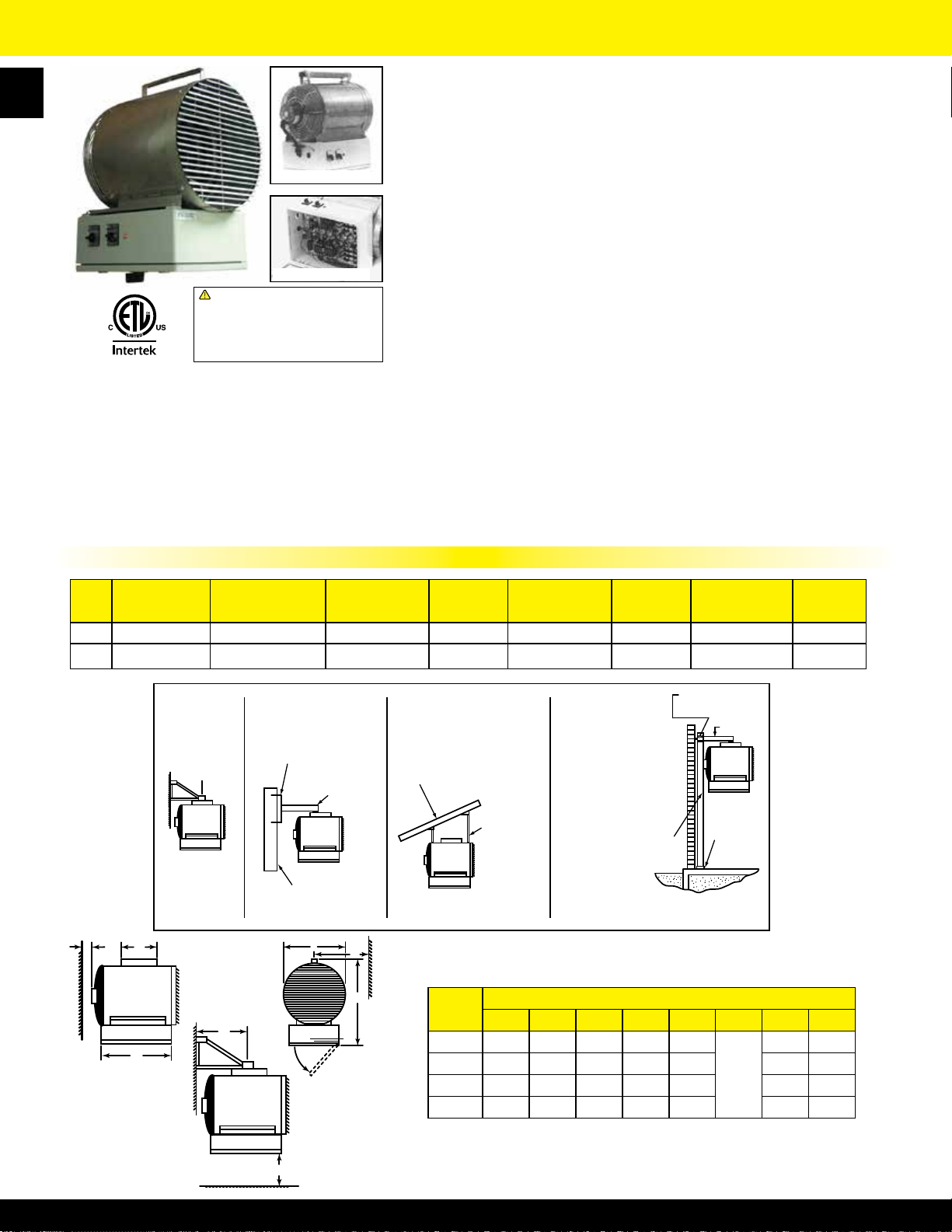
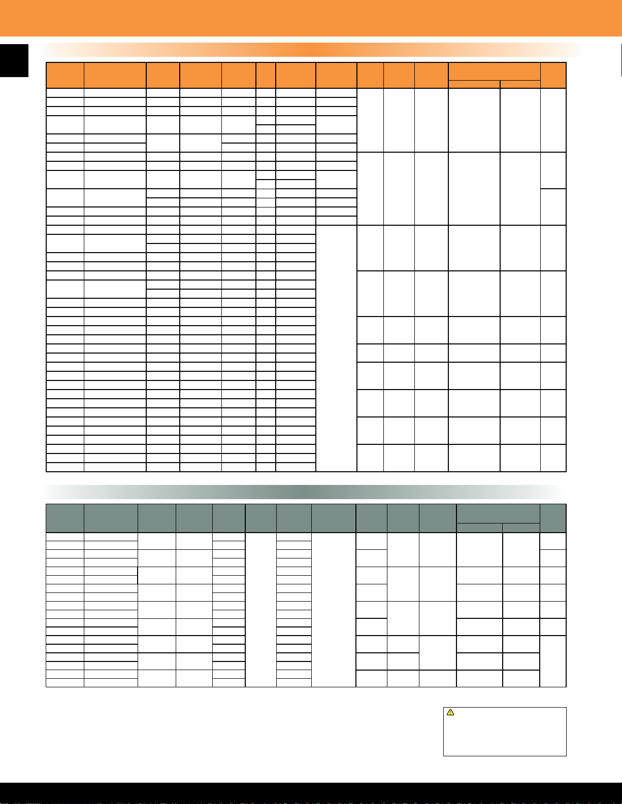
UH Series Horizontal Fan Forced Unit Heater
3.3 KW THROUGH 48 KW HORIZONTAL DISCHARGE SUSPENDED FAN FORCED UNIT HEATERS
AVAILABLE IN 1 OR 3 PHASE FOR ALL STANDARD VOLTAGES FROM 208V TO 480V.
CONSTRUCTION:
Heavy gauge welded steel cabinet with powder coated nish and control
compartment with a hinged and latched access door, simplifying wiring installation
and maintenance
HEATING ELEMENT:
Circular copper clad steel sheath element with continuously brazed steel ns formed
to match the air delivery pattern of the fan blade
OVERHEAT PROTECTION:
All units come equipped with automatic resetting type limit controls to de-energize
the heater should an over-temperature situation occur
FAN and MOTOR:
Totally enclosed, single phase, permanently lubricated, thermally protected motors
!
WARNING: This product can expose you
to chemicals including nickel which is known
to the State of California to cause cancer,
and chromium, which is known to the State
of California to cause birth defects and/or
reproductive harm. For more information go
to www.P65Warnings.ca.gov.
FACTORY INSTALLED OPTIONS:
• 24 Volt transformer on 3 KW to 15KW units to
convert from line voltage to low voltage remote
thermostat operation.
• Summer fan switch to operate the fan only.
• Fan delay switch to purge all residual heat from the
unit after the heating element has cycled off.
• Powder coated epoxy nish for corrosive atmospheres.
• Disconnect switch.
• Made in U.S.A.
MAXIMUM RECOMMENDED
MOUNTING HEIGHT
3 - 10 KW 9 FT.
12 - 15 KW 10 FT.
20 - 30 KW 13 FT.
40 - 48 KW 16 FT.
with unit bearings on 3 KW - 10 KW models and sleeve bearings on 12.5 KW - 48
KW models - mounted with rubber insulators to minimize vibration and noise. Fan
assembly enclosed by a heavy gauge, close spaced, chrome plated wire guard
LOUVER ASSEMBLY:
Louvers are individually adjustable for directional control of air ow and the entire
assembly can be repositioned in the eld from down ow to up ow or
left / right directional air ow
TEMPERATURE CONTROLS:
20 KW through 48 KW units and all 480V have built in 24 Volt transformer for low
voltage remote thermostat application. 25 KW through 48 KW models available in
2-stage on special order (consult factory)
INSTALLATION:
Unit Heaters can be mounted with the motor shaft from horizontal to downward at
45° off horizontal. Pre-drilled holes and installed threaded nuts provided to allow
hanging by threaded rods -
1
⁄4” for units up to 15 KW and 5⁄16” for 20 KW units and
larger. Optional wall / ceiling mounting brackets are available for all units
NOTE: Louver assembly is square and mounted with screws. Louver can be
removed and repositioned for four (4) directional air ow - left - right - up - down
with the heater in the horizontal position.
Product Dimensions & Model Number Designation
Dimensions A B C
Figure 1:
3.3, 5, 7.5, 10 KW
A
Figure 2:
12.5, 15 KW
Figure 3:
B
3.3 KW THROUGH 15 KW UNIT HEATERS 20 KW THROUGH 48 KW UNIT HEATERS
A
B
Figures 3 & 4 shown with standard mounting tabs for units over 20 KW. Optional UHB-3 and UHB-4 wall brackets are available.
3.3 KW thru 15 KW units can be mounted using
B
1
⁄4” threaded rod. 20 KW thru 48 KW units can be mounted using 5⁄16” threaded rod.
A
20, 25, 30 KW
Figure 4:
40, 48 KW
20” 11” 13”
22” 11” 15”
24” 17” 17”
26” 23” 19”
Factory & Field Installed Accessories
FACTORY INSTALLED OPTIONS
SUFFIX DESCRIPTION
CA1F
CA2F
F
S Summer Fan Switch
CA1 24v Transformer (3.3 KW - 15 KW units) & Contactor
CA2 120v Transformer (3.3 KW - 15 KW units) & Contactor
E Epoxy Coating
T SPST Thermostat (40°F - 110°F)
D
Heat purge fan delay switch includes 24v transformer
and contactor on 208-240-277 volt units
Heat purge fan delay switch includes 120v transformer
and contactor on 208--240-277 volt units
Heat purge fan delay switch on 480v units CA1
low voltage transformer and contactor included
30 Amp Disconnect Switch: 0-24 Amps
40 Amp Disconnect Switch: 24.1-32 Amps
80 Amp Disconnect Switch: 32.1-64 Amps
100 Amp Disconnect Switch: 64.1-80 Amps
MFG
CATALOG
NUMBER
06462302 DCS303 30 Amp Disconnect Kit: 0-24 Amps
06462402 DCS403 40 Amp Disconnect Kit: 24.1-32 Amps
06462502 DCS803 80 Amp Disconnect Kit: 32.1-64 Amps
06462602 DCS1003 100 Amp Disconnect Kit: 64.1-80 Amps
06879902 TUH1
06991002 UHB-1
06991102 UHB-3
06991202 UHB-4
FIELD INSTALLED ACCESSORIES
MFG
MODEL
NUMBER
DESCRIPTION
25 Amp SPST Thermostat Kit
(40°F - 110
Wall / Ceiling Bracket
3.3 KW - 15 KW units
Wall / Ceiling Bracket
20 KW - 30 KW units
Wall / Ceiling Bracket
35 KW - 48 KW units
O
F)
Page 14
HOW TO DESIGNATE A MODEL:
UH Series Horizontal Fan Forced Unit Heater
Element Volts
F = 208
H = 240
HF = 240/208
Phase
1 = 1-Phase
2 = 1 or 3-Ph.
3 = 3-Phase
G = 277
P = 480
Factory Installed Options (use as a suffix on model designation):
S = Summer Fan Switch, F = Fan Delay, D = Disconnect, T = Built-in Thermostat, E = Epoxy Coated
Field Installed Options :
Disconnect Switch, Built-in Thermostat, & Wall / Ceiling Bracket
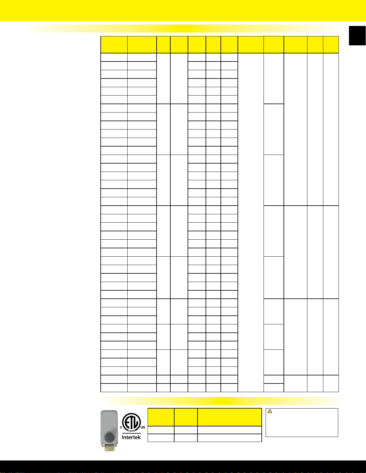
MFG
CATALOG
NUMBER
06446002 F1FUH03003
06446602 H1HUH03003 240 1 13.8 240
06447202 G1GUH03003 277 1 11.9 277
07114802 H3HUH03C03 240 3 7.9 240
07114902 F3FUH03C03 208 3 9.2 208
07114002 P3PUH03CA1 480 3 4 24
06446102 F1FUH05003
06447302 G1GUH05003 277 1 18.1 277
06449302 F2FUH05C03 208 1 or 3 24.1 / 14.0 208
06448802 P3PUH05CA1 480 3 6.1 24
07180502 F1FUH07CA1
07173702 H1HUH07CA1 240 1 31.3 24 41
07151802 G1GUH07CA1 277 1 27.1 24 41
06447902 F3FUH07C03 208 3 20.8 208
06448902 P3PUH07CA1 480 3 9.1 24
07170902 F1FUH10CA1
06808402 H1HUH10CA1 240 1 41.7 24
07173802 G1GUH10CA1 277 1 36.1 24
06449602 F2FUH10C03 208 1 or 3 48.1 / 27.8 208
06449702 HF2BUH10C03 10 / 7.5
07114202 P3PUH10CA1 10.0 34100 480 3 12.1 24 55 51
06446402 F1FUH12C03
06447002 H1HUH12C03 240 1 52.1 240
06448102 F3FUH12C03 208 3 34.7 208
06448602 H3HUH12C03 240 3 30.1 240
07114302 P3PUH12CA1 480 3 15.1 24
06446502 F1FUH15CO3
06447102 H1HUH15C03 240 1 62.5 240
06448202 F3FUH15C03 208 3 41.7 208
06448702 H3HUH15C03 240 3 36.1 240
07114402 P3PUH15CA1 480 3 18.1 24
06883002 F1FUH20CA1*
06884202 H1HUH20CA1* 240 1 83.3 24
06883102 F3FUH20CA1 208 3 55.6 24
06884302 H3HUH20CA1 240 3 48.2 24
06883202 P3PUH20CA1 480 3 24.1 24
06884402 F1FUH25CA1
06883302 H1HUH25CA1 240 1 104.2 24
06884502 F3FUH25CA1 208 3 69.5 24
06883402 H3HUH25CA1 240 3 60.2 24
06884602 P3PUH25CA1 480 3 30.1 24
06884702 H1HUH30CA1
06883602 F3FUH30CA1* 208 3 83.4 24
06884802 H3HUH30CA1 240 3 72.3 24
06883702 P3PUH30CA1 480 3 36.1 24
06884002 P3PUH40CA1 40.0 136500 480 3 48.2 24 55
06887802 P3PUH48CA1 48.0 163800 480 3 57.8 24 67 56’ 2275 16’ 78
MFG
MODEL
NUMBER
*Disconnect not available
H 2 H UH 10 C A 1
Motor Voltage
F = 208
H = 240
B = 240 / 208
G = 277
P = 480
Model Series
UH
Element KW
Standard Product Models
KW BTUs VOLTS PH AMPS
208 1 15.9 208
3.3 11200
208 1 24.1 208
5 17100
208 1 36.1 24
7.5 25600
208 1 48.1 24
10.0 34100
34100 240 1 or 3 41.7 / 24.1 240 55
25600 208 1 or 3 36.1 / 20.8 208 42
208 1 60.1 208
12.5 42600
208 1 72.1 208
15.0 51200
208 1 96.2 24
20.0 68300
208 1 120.2 24
25.0 85300
240 1 125 24
30.0 102390
CONTROL
VOLTS
Control System
O = None
C = Contactor
Transformer
O = None
A = Included
Control Volts
1 = 24
2 = 120
3 = Element
Voltage
4 = 240
TEMP
RISE °F
26 26’ 400 9’ 36
40 26’ 400 9’
42 36’ 575 9’
55
49 45’ 800 10’ 45
59 45’ 800 10’ 54
47 56’ 1350 13’ 55
58 56’ 1350 13’ 55
70 56’ 1350 13’ 60
AIR
THROW
36’ 575 9’
56’ 2275 16’ 75
CFM
RECOM’D
MOUNTING HT.
WT.
(LBS)
3606446702 H1HUH05003 240 1 20.8 240
4406449402 H2HUH05C03 240 1 or 3 20.8 / 12.1 240
40
4406449502 H2HUH07C03 240 1 or 3 31.3 / 18.1 240
42
45
13
Page 15
14
5100 Series Horizontal or Vertical Mounted Fan Forced Unit Heater
3.3 KW THROUGH 50 KW SUSPENDED FAN FORCED UNIT HEATERS AVAILABLE IN 1 OR 3 PHASE FOR ALL STANDARD
VOLTAGES FROM 208V TO 480V THAT CAN BE MOUNTED TO PROVIDE HORIZONTAL OR VERTICAL DISCHARGE
CONSTRUCTION:
Heavy 18 gauge welded steel cabinet with powder coated nish and control
compartment housing a master terminal board with a hinged and latched
access door, simplifying wiring, installation & maintenance.
HEATING ELEMENT:
Copper clad steel sheath element with continuously brazed steel ns formed
to allow side draw through air ow.
OVERHEAT PROTECTION:
All units come equipped with automatic reset type limit controls to de-energize
the heater should an over-temperature situation occur.
FAN and MOTOR:
Totally enclosed, 1-speed, 1-phase, permanently lubricated, thermally
protected motors with unit bearings on 3 KW - 20 KW models. Totally
enclosed, 2-speed, 1-phase, permanently lubricated, thermally protected
Horizontal Discharge
!
WARNING: This product can expose you
to chemicals including nickel which is known
to the State of California to cause cancer,
and chromium, which is known to the State
of California to cause birth defects and/or
reproductive harm. For more information go
to www.P65Warnings.ca.gov.
Taskmaster Dimensions
W
D
Vertical Discharge
KW
RATING
H
3.3 - 5.0 17
7.5 - 10.0 24 5⁄16 21 1⁄2 6 1⁄2
15.0 - 20.0 28 11⁄16 21 1⁄2 6 1⁄2
25.0 - 50.0 34 29 1⁄4 10 1⁄16
DIMENSIONS (inches)
H W D
3
⁄4 14 15⁄32 6 1⁄2
motors with sleeve bearings on 25 KW - 50 KW models. All motors mounted
with rubber insulators to minimize vibration & noise. Fan over-ride purges unit
of residual heat at shutdown.
LOUVER ASSEMBLY:
Louvers are individually adjustable for directional control of air ow up to 15°
from straight horizontal. Optional diffusers available for down ow (vertical
discharge) applications.
TEMPERATURE CONTROLS:
Optional low voltage and line voltage thermostats available with an adjustable
temperature range of 40°F to 110°F. Units with model numbers ending in CA1
are factory wired for low voltage controls. 25 KW through 50 KW units are
designed for two stage heating operation.
INSTALLATION:
Unit Heaters can be mounted for horizontal or vertical discharge.Applications
up to 6000 ft. See UH Series above 6000 ft.
FEATURES:
• Made in U.S.A.
FIELD INSTALLED OPTIONS:
• In-unit or wall mounted temperature control thermostats low or line voltage
• Summer fan switch to operate the fan only
• Power disconnect switch
• Heat stratication thermostat
Installing the Taskmaster Series
DETERMINING HEATER REQUIREMENTS
Calculate the heating loads using the NEMA handbook or ASHRAE guide. Then determine the quantity and size of unit
heaters to be used. To maintain uniform heat and reduce stratied air, it is recommended that the total CFM of the units turn
the air over approximately 3 times per hour. In instances where a large group of people are located and normally in the
same area, use a large number of lower KW unit heaters. In warehouse areas or storage rooms where heat distribution and
constant temperatures are less important, use fewer heaters of higher capacity.
HORIZONTAL MOUNT
Small rooms can be heated by one unit heater. Where two walls are exposed, heaters should be mounted as shown in Figure
A. In larger rooms, units should he located so their air streams wipe exposed walls without blowing at them. Units should be
located so that the air stream of one supports that of another thus setting up a circulatory air movement shown in
(Distance between units to be approximately 1-1/2 times published air throw.) Units should not be mounted horizontally in
areas having ceiling heights in excess of 15-18 ft.
VERTICAL MOUNT
Units should be mounted vertically in high bay areas, or where heater location would not interfere with plant operation or
trafc, Heaters should be situated to provide free air circulation. Size and selection of units should be based on recommended
mounting height. Optional diffusers may best be employed to reduce high air velocity and at the same time disperse heated
air in a uniform pattern. When unit heaters are used to combat cold air inrush from opened loading dock doors, one or more
units should be arranged to blow warm air across opening (Figure C).
DUAL MOUNTING
Where square footage is large and comfort essential, both horizontal and vertical installations may best serve your
requirements as Figure D demonstrates.
Note: Products in this section with factory installed controls are subject to 100% cancellation/restocking charges.
Figure
B.
Page 16
HOW TO DESIGNATE A MODEL:
5100 Series Horizontal or Vertical Mounted Fan Forced Unit Heater
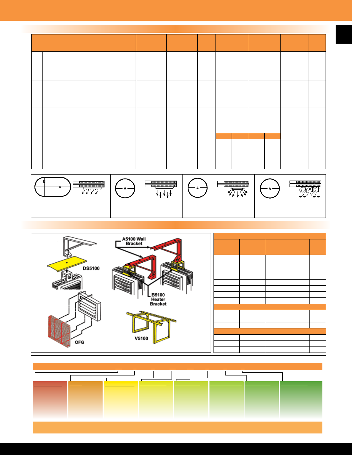
Diffuser Options
DESCRIPTION
Louver Diffuser (Standard)
Louvers can be individually adjusted for
1
rectangular coverage over doorways as
an air curtain, or to meet rectangular oor
pattern heating requirements.
General Distribution (No Diffuser)
The 5100 air chute venturi permits general
2
down ow air pattern distribution as required
at a higher mounting height.
3
4
Anemostat Diffuser (Optional)
For applications where draft restriction is
required at lower unit mounting heights.
Radial Diffuser (Optional)
Individually adjustable ns permit increased
oor coverage at 45° open. Additional throw
is accomplished when ns are 90° vertical.
(Please allow for higher mounting heights.)
MFG
CATALOG
NUMBER
NA Standard
NA
06926802
06811802
06811802
07220702
06926602
06926602
06926702
06926702
07220802
MFG
MODEL
NUMBER
Not
Required
AD5120
AD5150
AD5150
AD5175
RD5120
RD5120
RD5150
RD5150
RD5175
KW
USED
3.3-5
7.5-10
25-30
40-50
3.3-5
7.5-10
25-30
40-50
7.5-10
25-30
40-50
60-70
7.5-20
25-50
60-70
MAX
MOUNTING
HEIGHT (ft.)
9
12
18
22
24
9
12
18
22
24
15
17
20
31
45° 90° 45° 90°
10
14
20
18
26
14
21
30
28
36
DIMENSION
A (feet)
20
40
52
75
84
15
30
40
55
64
38
50
60
-
36
42
62
68
72
30
35
44
54
60
DIMENSION
B (feet)
10
22
30
42
47
NA NA
NA
NA
WT.
(LBS)
NA
10
12
37
12
14
39
15
Description 1 Description 2 Description 3
Louver Diffuser
No Diffuser Anemostat Diffuser
Mounting Brackets & Model Designator
MFG
CATALOG
NUMBER
06926902 A5105 3.3 KW TO 5.0 KW 9
06927002 A5120 7.5 KW TO 20.0 KW 13
06927102 A5150 25.0 KW TO 50.0 KW 16
06886202 B5105 3.3 KW TO 20.0 KW 3
06886302 B5150 25.0 KW TO 50.0 KW 8
06928402 V5105 3.3 KW TO 5.0 KW 9
(*Included with
A5100 bracket.)
Not actual colors. Red & yellow shading is for diagram clarity only.
06928502 V5120 7.5 KW TO 20.0 KW 13
06928602 V5150 25.0 KW TO 50.0 KW 16
06928702 DS5105 3.3 KW TO 5.0 KW 3
06928802 DS5120 7.5 KW TO 20.0 KW 4
06812202 DS5150 25.0 KW TO 50.0 KW 5
07065402 OFG5101 3.3 KW TO 5.0 KW 3
07065502 OFG5102 7.5 KW TO 20.0 KW 4
07065602 OFG5103 25.0 KW TO 50.0 KW 5
HF 2 B 51 10 C A 1
Description 4
Radial Diffuser
MOUNTING BRACKETS
MFG
MODEL
NUMBER
DUST SHIELD
MODEL SIZE
FAN GUARD
WT.
(LBS)
Element Volts
F = 208
H = 240
HF = 240/208
G = 277
P = 480
Phase
1 = 1-Phase
2 = 1 or 3-Ph.
3 = 3-Phase
Motor Voltage
F = 208
H = 240
B = 240 / 208
G = 277
P = 480
Model Series
51
Element KW Control System
Blank = None
C = Contactor
Transformer
Blank = None
A = Included
Control Volts
1 = 24
2 = 120
(with CA option)
Page 17
16
5100 Series Horizontal or Vertical Mounted Fan Forced Unit Heater
Standard Taskmaster Models & Series Notes
MFG
CATALOG
NUMBER
06450802 F1F5103N 3.3 11.2 208 1 15.9 / 9.17 208
06451002 HF1B5103N 3.3/2.5 11.2 / 8.5 240/208 1 13.7 / 11.9 240 / 208
06456802 F2F5103N 3.3 11.2 208 1 / 3 15.9 / 9.17 208
06457002 HF2B5103N 3.3/2.5 11.2 / 8.5 240/208
06457202 G1G5103N
06451202 P3P5103CA1N* 480 3 4.0 24
06455402 F1F5105N 5.0 17.1 208 1 24.1 208
06455602 HF1B5105N 5.0/3.7 17.1 / 12.8 240/208 1 20.9 / 18.1 240 / 208
06451402 F2F5105N 5.0 17.1 208
06451602 HF2B5105N
06458402 G1G5105N 5.0 17.1 277
06451802 P3P5105CA1N* 5.0 17.1 480 3 6.1 24
06452002 F2F5107CA1L* 7.5 25.6 208 1 / 3 36.1 / 20.8
06452202 HF2B5107CA1L*
06459202 G1G5107CA1L* 7.5 25.6 277 1 27.1
06452402 P3P5107CA1N* 7.5 25.6 480 3 9.1
06452602 F2F5110CA1L* 9.9 33.8 208 1 / 3 47.8 / 27.4
06452802 HF2B5110CA1L*
06456402 G1G5110CA1N* 10.0 34.1 277 1 36.1
06453002 P3P5110CA1N* 10.0 34.1 480 3 12.4
06453202 F3F5115CA1L* 15.0 51.2 208 3 41.7
06453602 P3P5115CA1N* 15.0 51.2 480 3 18.1
06453802 HF3B5120CA1L* 19.7/14.8 67.2 / 50.5 240/208 3 47.8 / 41.1
06454002 P3P5120CA1N* 20.0 68.3 480 3 24.1
06458802 F3F5125CA1L* 25.0 85.3 208 3 69.5
06459402 HF3B5125CA1L* 25.0/18.7 85.3 / 64.0 240/208 3 60.2 / 52.1 40/44°F 45’ 12’ 22’ 120
06459802 P3P5125CA1N* 25.0 85.3 480 3 30.1
06454202 F3F5130CA1L* 30.0 102.4 208 3 83.4
06454402 HF3B5130CA1L* 30.0/22.5 102.4 / 76.8 240/208 3 72.3 / 62.5 47/53°F 40’ 12’ 20’ 120
06454602 P3P5130CA1N* 30.0 102.4 480 3 36.2
06440402 F3F5140CA1L* 40.0 136.5 208 3 111 .2
06440602 HF3B5140CA1L* 40.0/30.0 136.5/102.4 240/208 3 96.4 / 83.4 40/45°F 55’
06440802 P3P5140CA1N* 39.0 133.1 480 3 47.0
06454802 F3F5150CA1L* 49.6 169.3 208 3 139.0
06455002 HF3B5150CA1L* 50.0/37.5 170.6/128.0 240/208 3 120.5/104.3 51/56°F 50’
06455202 P3P5150CA1N 50.0 170.6 480 3 60.3
*Optional wall mounted energy saving SDHW1001 Thermostat recommended
MFG
MODEL
NUMBER
KW BTUs / H VOLTS PH AMPS
1 / 3 13.7 / 11.9
3.3 11.2
5.0 17.1 240 1 / 3 20.8 / 18.1 240
3.7 12.8 208 1 / 3 17.1 / 10.4 208
7.5 25.6 240 1 / 3 27.1 / 16.04
5.6 19.2 208 1 / 3 31.3 / 27.1
10.0 34.1 240 1 / 3 41.2 / 24.0
7.5 25.6 208 1 / 3 36.1 / 20.8
277 1 11.9 277
3 7.9 / 6.9
1 / 3 24.1
3
1
CONTROL
VOLTAGE
240 / 208
13.9
18.1 277
208
24
TEMP
RISE
26
40
34°F 22’ 700 10’ 12’ 54
45°F 22’ 700 10’ 14’ 55
57°F 32’ 1100 12’ 18’ 65
AIR
THROW
o
F 12’ 400 9’ 9’ 25
o
F 12’ 400 9’ 9’
CFM
1100 6406453402 HF3B5115CA1L* 15.0/11.2 51.2 / 38.4 240/208 3 36.1 / 31.3 43°F 32’ 11 ’ 20’
2000/1800
2000/1800
3100/2800
3100/2800
International Models
MFG
CATALOG
NUMBER
07153002 Q3H5103CA1
07249202 R3H5103CA1 415 4.6
07249302 Q3H5105CA1
04249402 R3H5105CA1 415 6.96
07171302 Q3H5107CA1
07249502 R3H5107CA1 415 10.5
06865702 Q3H5110CA1
07249602 R3H5110CA1 415 13.9
07249702 Q3H5115CA1
07249802 R3H5115CA1 415 20.9
07041702 Q3H5120CA1
07249902 R3H5120CA1 415 27.85
07191902 Q3H5125CA1
07106102 R3H5125CA1 415 34.8
07250002 Q3H5130CA1
07106202 R3H5130CA1 415 41.8
07250102 Q3H5140CA1
07098302 R3H5140CA1 415 55.7
• For 24V control add “CA1” sufx. • For 120V control add “CA2” sufx. • For other voltages consult factory.
NOTES:
• 25-50KW models are wired for single or two stage heating and have two speed motors.
• Air delivery and motor data on dual voltage units reect higher voltage.
• 600V models available 5-48.5 KW. Use “U” prex to designate 600v and use 480v pricing.
• Supply wire on 40 and 50 KW models should have rated insulation of 75oC minimum.
• Use T5122 for two stage control.
• Use TW123 for two stage control.
• Use TFS5102 for two stage control.
• Wall thermostat must be used when built-in stratication thermostat is required.
MFG
MODEL
NUMBER
KW BTUs / H VOLTS PH AMPS
3.3 11263
5.0 17065
7.5 25600
10.0 34130
15.0 51195
20.0 68260
25.0 85325
30.0 102390
40.0 136520
380
380 7.6
380 11.4
380 15.2
380 22.8
380 30.4
380 38.0
380 45.6
380 60.85
5.02
3
CONTROL
VOLTAGE
24
TEMP
RISE
40/44 45’
47/53 40’ 12’ 20’
40/45 55’ 3100/2800 15’ 24’
AIR
THROW
26
12’ 400 9’ 9’
40 27
34
22’ 700
45 10’ 14’ 55
43
32’ 1100
57 12’ 18’ 65
CFM
2000/1800
RECOMMENDED
MOUNTING HT.
Horizontal Vertical
15’ 24’ 120
15’ 22’ 120
RECOMMENDED
MOUNTING HT.
Horizontal Vertical
10’ 12’ 54
11’ 20’ 64
12’ 22’
!
WARNING: This product can expose you
to chemicals including nickel which is known
to the State of California to cause cancer,
and chromium, which is known to the State
of California to cause birth defects and/or
reproductive harm. For more information go
to www.P65Warnings.ca.gov.
WT.
(LBS)
WT.
(LBS)
120
25
27
25
Page 18
5100 Series Horizontal or Vertical Mounted Fan Forced Unit Heater
Recommended Control Options, Control Accessory Options, & Control Accessories
MFG
MODEL
NUMBER
F1F5103N
HF1B5103N
F2F5103N
HF2B5103N
G1G5103N DCS 202 NA
P3P5103CA1N NA DCS 403 RK120EAA FS5102 FSW5112 TFS5101 TC5102 NA
F1F5105N
HF1B5105N ET9STS
F2F5105N
HF2B5105N
G1G5105N DCS 403 NA
P3P5105CA1N NA DCS 403
F2F5107CA1L
HF2B5107CA1L
G1G5107CA1L DCS 403 NA NA
P3P5107CA1L NA DCS 403 FS5102 FSW5112 TC5102 NA
F2F5110CA1L
HF2B5110CA1L
G1G5110CA1N DCS 603 NA NA
P3P5110CA1N
F3F5115CA1L DCS 603
HF3B5115CA1L DCS 603
P3P5115CA1L DCS 403 FS5102 FSW5112 NA
HF3B5120CA1L DCS 603 FS5101 FSW5111 TC1602
P3P5120CA1N DCS 403 FS5102 FSW5112 NA
F3F5125CA1L
HF3B5125CA1L
P3P5125CA1N DCS 403 FS5102 FSW5112 NA
F3F5130CA1L NA
HF3B5130CA1L DCS 1003
P3P5130CA1N DCS 603 FS5102 FSW5112 NA
F3F5140CA1L NA
HF3B5140CA1L NA
P3P5140CA1N DCS 603 FS5102 FSW5112 NA
F3F5150CA1L
HF3B5150CA1L
P3P5150CA1N DCS 1003 FS5102 FSW5112 NA
CONTROL ACCESSORY OPTIONS - FIELD INSTALLED IN HEATER
MFG
CATALOG
NUMBER
07171502 DCS202 / 5100 20 AMP; 0-16 Amps
07171602 DCS403 / 5100 40 AMP; 16.1-32 Amps
07171702 DCS603 / 5100 60 AMP; 32.1-48 Amps
07171802 DCS1003 /5100 100 AMP; 48.1-80 Amps
*Disconnect must be rated at 80% of total ampload.
06927702 T5100
06927802 T5102
LOW VOLTAGE THERMOSTAT (ALL CA1 MODELS)
06927702 T5100
06927902 T5122
06928002 TC5102
06928102 TC5103 SPST; LINE DUTY; AMP 120-240V; 70-130°
06928202 FS5101 SPST; LINE VOLT ;120-277V
06928302 FS5102 SPST; LINE VOLT ; 480-600V
DISCONNECT
SWITCH
1 Ø 3 Ø IN-BUILT
DCS 202 NA T5100 ET9STS
NA DCS 403 T5102 TW 1512
DCS 202 NA T5100 ET9STS
NA DCS 403 T5102 TW 1512
DCS 403 NA
NA DCS 403 T5102 TW 1512
DCS 403 NA T5100 ET9STS
NA DCS 403 T5102 TW 1512
DCS 403 NA
NA DCS 403
DCS 403 NA
NA DCS 403
DCS 603 NA
NA DCS 403
DCS 603 NA
NA DCS 403
DCS 403 FS5102 FSW5112
DCS 1003
NA
NA FS5101 FSW5111 TC1602
MFG
MODEL
NUMBER
POWER DISCONNECT SWITCH*
LINE VOLTAGE THERMOSTAT
25 AMP, 24-277V , (40-110
DPST; LINE DUTY 25 AMP 120-277V
25 AMP, 120-277V , (40-120
SPST; LOW VOLT/PILOT DUTY; 125VA;
(3.3-20 KW UNITS) , (40-110
2-STAGE; LOW VOLT; 125VA;
STRATIFICATION THERMOSTAT
SUMMER FAN SWITCH
(25-50 KW UNITS) , (40-100
SPST; LOW VOLT/PILOT DUTY
THERMOSTAT
WALL
MOUNTED
ET9STS NA
T5100
T5100
T5100 SDHW1001
DESCRIPTION
SPST; PILOT DUTY
(W/RELAY) ; 70-130°
S2025
S2025
S2025 NA
R K1 2 0 E A A
o
F)
o
F)
o
F)
o
F)
SUMMER FAN
SWITCH
IN-BUILT
FS5101 FSW5111 NA
FS5101 FSW5111 NA
FS5102 FSW5112
FS5101 FSW5111
FS5101 FSW5111
FS5101 FSW5111 TC1602
FS5101 FSW5111
FS5101 FSW5111 TC1602
FS5101 FSW5111 TC1602
WALL
MOUNTED
THERMOSTAT &
SUMMER FAN SWITCH
WALL MOUNTED
TFS5101
TFS5101
STRATIFICATION
THERMOSTAT
IN-BUILT
TC5103
TC5103
TC5102 NA
TC5103
TC5103
TC5103
WALL
MOUNTED
TC1602
TC1602
TC1602
TC1602
TC1602
NA
CONTROL ACCESSORIES - REMOTE WALL MOUNTED
MFG
CATALOG
NUMBER
MFG
MODEL
NUMBER
DESCRIPTION
LINE VOLTAGE THERMOSTAT
05029102 S2025H10AA** SP; 25 Amp; 120-277Vl; 50-90°F
05238902 ET9STS** SP; 22 Amp; 120-277V; 50-90°F
06910902 TW1512* DPST; 25 AMP; 120-277V; 50-90°F
LOW VOLTAGE THERMOSTATS (ALL CA1 MODELS)
05260102 RK120EAA 24VAC or MV; 50°-90°F
05236402 SDHW1001***
MULTI-STAGE; 50-90°F
STRATIFCATION THERMOSTAT
06911002 TC1602 SPST; LINE VOLT; 120-277V; 70-140°
SUMMER FAN SWITCH
06926202 FSW5111 SPST; LINE VOLT; 120-277V
06926302 FSW5112 SPST; LOW VOLT; (W/RELAY)
LOW VOLTAGE THERMOSTAT & SUMMER FAN SWITCH(W/RELAY)
(CA1 MODELS)
06926402 TFS5101 SPST; LOW VOLT; 50-90°
06926502 TFS5102
*Use DPST double line break thermostat for 3-phase line voltage control in non “C” models.
**Any SPST thermostat of sufcient amperage may be substituted.
*** For complete specications, refer to page 105.
ELECTRONIC; 1 OR 2 STAGE; LOW VOLT; 40° - 90°F
17
Page 19
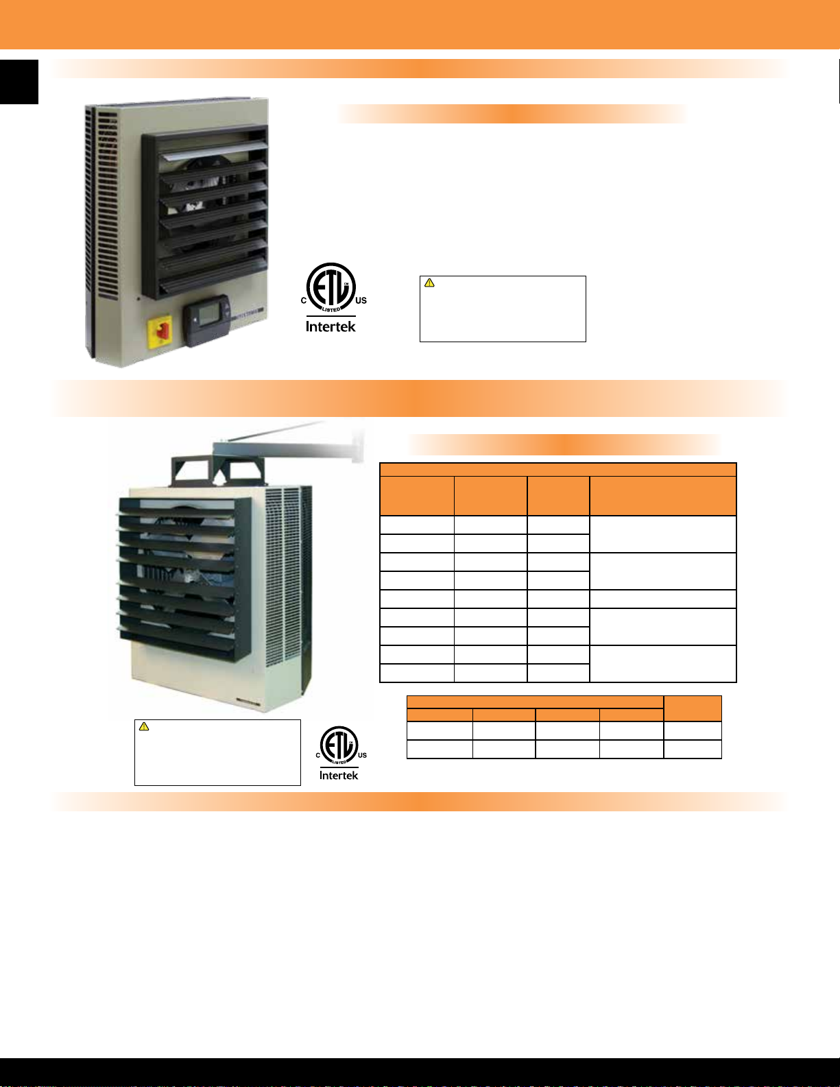
18
5100 Series Horizontal or Vertical Mounted Fan Forced Unit Heater
Available With Setback On Demand (SD) Thermostat Factory Installed
5100 SD Features
• 24-Volt Control
• Factory pre-programmed - just set your setback temperature in the eld
• Setback feature allows up to 12 degree setback with easy-to-use adjustable slide switch
• Occupancy sensor defaults to economy mode after one hour, sensor has 94 degree angular
range and a 16’ linear range
• Temperature range of 50-90 degrees
• Up to two stage operation on 5103-5150 Series and up to four stages on 5160-51100 Series
• 65-second delay between stages
• Add “SD” as sufx to heater model number for factory built in option
!
WARNING: This product can expose you
to chemicals including nickel which is known
to the State of California to cause cancer,
and chromium, which is known to the State
of California to cause birth defects and/or
reproductive harm. For more information go
to www.P65Warnings.ca.gov.
5100 Series 60 KW - 100 KW Suspended Fan Forced Unit Heater
Mounting Brackets and Accessories
Mounting Brackets
MFG
CATALOG
NUMBER
07220002 A5175 60 To 70
07220102 A51100 80 to 100
07220302 B5175 60 to 70
07220402 B51100 80 to 100
MFG
MODEL
NUMBER
KW DESCRIPTION
Wall/Ceiling Bracket
Heater Bracket
07220202 V51100 60 to 100 Vertical Bracket
!
WARNING: This product can expose you
to chemicals including nickel which is known
to the State of California to cause cancer,
and chromium, which is known to the State
of California to cause birth defects and/or
reproductive harm. For more information go
to www.P65Warnings.ca.gov.
07220502 DS5175 60 to 70
07220602 DS51100 80 to 100
07220902 OFG 5175 60 to 70
07221002 OFG 51100 80 to 100
Dimensions (Inches)
KW H W D
1
60-70 35
80-100 39
⁄2 30 1⁄2 14 1⁄2 141
1
⁄2 37 5⁄8 18 1⁄2 202
Dust Shield
Fan Guard
WT.
(LBS)
Features & Specications
CONSTRUCTION:
Heavy gauge steel cabinet with powder coated nish and control compartment housing a master terminal board. The control compartment allows
for access through a hinged and latched door, simplifying wiring, installation, and maintenance. Made in U.S.A
HEATING ELEMENT:
The heating element is a copper clad steel sheath element with continuously brazed steel ns formed to allow side draw through air ow.
OVERHEAT PROTECTION:
All units come equipped with manual reset type limit controls to de-energize the heater should an over-temperature situation occur.
FAN & MOTOR:
Single speed, single phase permanently lubricated, thermally protected motors with ball bearings. The fan override purges the unit of residual
heat at shutdown.
FIELD INSTALLED OPTIONS:
Summer fan switch to operate the fan only, and a heat stratication thermostat for high bay areas.
HEATER STAGING:
60 KW and 70 KW are three stage; 80 KW, 90 KW, & 100 KW are four stage.
SC5100 FACTORY INSTALLED ELECTRONIC STEP CONTROLLER:
The optional factory installed step controller is a rst on last off sequencer that will cycle the unit heater stages through an optional wall thermostat.
Additionally, the step controller can be controlled by any building management system with 4 to 20 MA or 0 - 10 VDC eld supplied control signal.
Page 20
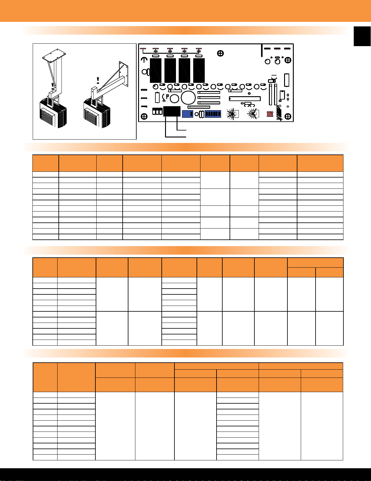
COM
001-0102
S
V
C4
C1
C2 C3
POWER
REV.1
JUNE 99
32
200
ON
90
100
TEST
1
2
60
4
3 56
DELAY(s)
150
RATIO(%)
ON
1
1
2
3
3
1
2
4
4MA-O%HEAT
20MA-100%HEAT
0-10VDC-CONTROL
OR C1025 WALL
THERMOSTAT
3 OR 4 STAGE
STEP CONTROL
INPUT
CONTROL
12030
VR1
VR2
C
+
_
5100 Series 60 KW - 100 KW Suspended Fan Forced Unit Heater
Optional Factory Installed Electronic Step Controller
3 OR 4 STAGE
STEP CONTROL
0-10VDC-CONTROL OR
VT7225 THERMOSTAT
Wall / Ceiling Bracket
Electrical Data
MFG
CATALOG
NUMBER
07213402 F3F5160CA1 60 204.7 208
07213502 HF3B5160CA1 60/45 204.7/153.6 240/208 144.6/125 200/175
07213602 P3P5160CA1 60 204.7 480 72.3 100
07214202 F3F5170CA1 70 238.9 208
07214302 HF3B5170CA1 70/52.5 238.9/179.2 240/208 168.7/145.8 225/200
07214402 P3P5170CA1 70 238.9 480 84.3 110
07217002 HF3B5180CA1 80/60 273/204.7 240/208
07217102 P3P5180CA1 80 273 480 96.3 125
07217602 HF3B5190CA1 90/67.5 307.1/230.4 240/208
07217702 P3P5190CA1 90 307.1 480 108.4 150
07218202 HF3B51100CA1 100/75 341.3/256 240/208
07218302 P3P51100CA1 100 341.3 480 120.4 175
MFG
MODEL
NUMBER
KW
BTUs / HR
(x 1000)
VOLTS PHASE
3 24
3 24
3 24
3 24
3 24
CONTROL
VOLTAGE
AMPS / PHASE
BRANCH CIRCUIT
PROTECTION SIZE
166.7 225
194.4 250
192.8/166.7 250/225
216.9/187.5 300/250
241/208.3 350/300
19
Air Delivery Data
MFG
CATALOG
NUMBER
07213402 F3F5160CA1
07213502 HF3B5160CA1 60/45
07213602 P3P5160CA1 60
07214202 F3F5170CA1 70
07214302 HF3B5170CA1 70/53
07214402 P3P5170CA1 70
07217002 HF3B5180CA1
07217102 P3P5180CA1 55
07217602 HF3B5190CA1 61/46
07217702 P3P5190CA1 61
07218202 HF3B51100CA1 68/51
07218302 P3P51100CA1 68
MFG
MODEL
NUMBER
CFM at
OUTLET
OUTLET
3400 1485
5000 1529
FPM at
TEMP RISE
°F
60
1/3 1100 50’ 18’ 31’
55/41
3/4 1100 65’ 22’ 40’
Recommended Control Options
STEP
CONTROLLER
CATALOG/
MODEL
MFG
CATALOG
NUMBER
MFG
MODEL
NUMBER
07213402 F3F5160CA1
07213502 HF3B5160CA1 FS5101
REMOTE
THERMOSTAT
CATALOG/
MODEL
07213602 P3P5160CA1 FS5102
07214202 F3F5170CA1 FS5101
07214302 HF3B5170CA1 FS5101
07214402 P3P5170CA1 FS5102
07217002 HF3B5180CA1 FS5101
05232302
SC5100
07217102 P3P5180CA1 FS5102
07217602 HF3B5190CA1 FS5101
07217702 P3P5190CA1 FS5102
07218202 HF3B51100CA1 FS5101
07218302 P3P51100CA1 FS5102
44046001
VT7225
(0-10VDC)
SUMMER FAN SWITCH STRATIFICATION THERMOSTAT
Wall Built-In Wall Built-In
CATALOG/
MODEL
06926302
FSW5112
HP MOTOR RPM AIR THROW
MODEL
CATALOG/
MODEL
FS5101
06926402
TFS5101
MAX MOUNTING
Horizontal Vertical
CATALOG/
MODEL
06928002
TC5102
Page 21
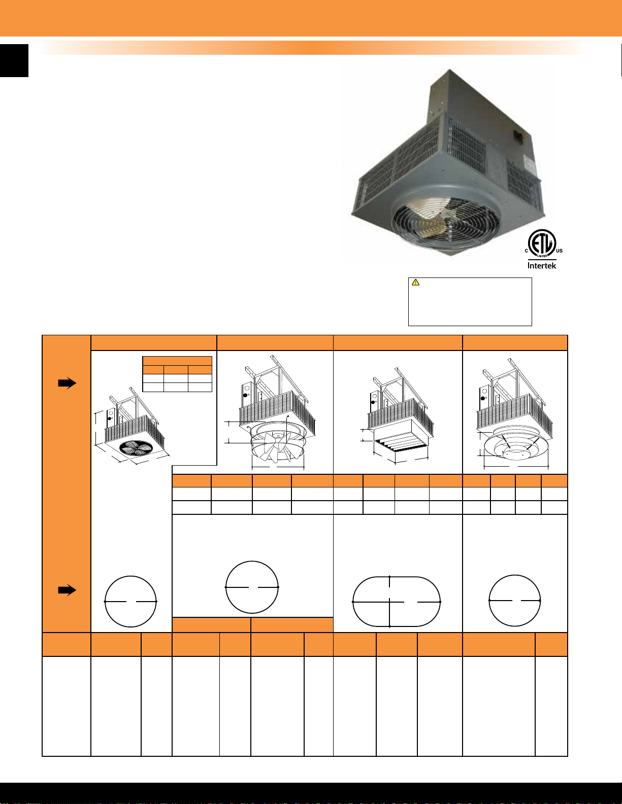
20
2600 Series Downow Unit Heater
General Description & Diffuser Information
CONSTRUCTION:
• 16 gauge steel cabinet with epoxy powder coated nish and control compartment with a hinged and
latched access door.
• OSHA guards standard with all models.
• Made in U.S.A
HEATING ELEMENT:
• Corrosion resistant element with steel sheath and steel spiral ns.
OVERHEAT PROTECTION:
• All units come equipped with manual reset limit controls to de-energize the heater should an
over-temperature situation occur.
FAN and MOTOR:
• Totally enclosed, 1 speed, 1 phase permanently lubricated, thermally protected
motors with unit bearings on 3KW - 20KW models. Totally enclosed, 2 speed,
1 phase permanently lubricated, thermally protected motors with sleeve bearings
on 24KW - 50KW models.
• Axial ow fan blade - 1570 RPM max.
• All models equipped with fan purge which allows fan to operate after
elements are de-energized to purge residual heat.
TEMPERATURE CONTROLS:
• 208V, 240V, 277V and 480V units have In-Built 24 Volt transformer for low
voltage remote thermostat application.
• 600V units have In-Built 240V control on 5-20 KW models, 25-50 KW models have
24V control.
• 25 KW - 50 KW models may operate as 2 stage heaters if 2 stage remote thermostat is used.
DISCONNECT SWITCH:
• All models equipped with In-Built disconnect except F3F2640, F3F2630CA1, F3F2650,
H3H2650, and H3H2640CA1.
INSTALLATION:
• Unit can be mounted using optional mounting bracket or eld constructed angle iron bracket.
• Not recommended for mounting with threaded rod or chain.
Standard Heater Anemostat DiffuserRadial Louvered Cone Diffuser Linear Louvered Diffuser
2600 Series shown with
standard wire guard.
Diffusers are eld installed.
!
WARNING: This product can expose you
to chemicals including nickel which is known
to the State of California to cause cancer,
and chromium, which is known to the State
of California to cause birth defects and/or
reproductive harm. For more information go
to www.P65Warnings.ca.gov.
Dimensions**
KW
20 ½”
5-20
25-50
A
B
For general distribution.
Choice of other diffusers
may be added after
installation if required.
O.S.H.A guard for
fan blade D1604 for
2605-2620, & D1614 for
2625-2650 Do not use
with other diffusers.
Diffuser Descriptions
MAX
MODEL
2605
2607
2610
2615
2620
2625
2630
2640
2650
*Minimum mounting height 6 feet.
**Dimensions are for all heater models without a diffuser option. Adding a diffuser will change the vertical (”A”) dimension of heater.
All mounting distances are in feet. All diagrams show optional mounting bracket.
MOUNTING
HEIGHT*
10
10
22
20
18
32
30
26
24
B
D'
D
(ft.)
25
25
40
44
48
48
60
64
68
A
B
15”
21 ½”
27”
A
B
MODEL MODEL MODELDIM: A DIM: A DIM: ADIM: B DIM: B DIM: B
D1600
D1610
VERTICAL 45 DEGREES OPEN
MAX
MOUNTING
HEIGHT
15
15
26
24
22
38
36
32
28
KW
5-20
25-50
With vanes vertical, straightens air for
higher mounting. Closed position for
broad horizontal coverage. Adjustable
for intermediate requirements.
(ft.)
25
25
36
38
40
42
50
50
50
D
6 ½"
11 ½"
D'
MAX
MOUNTING
HEIGHT
14 ¼"
24 ¾"
8
8
15
14
13
24
22
20
18
(ft.)
30
30
44
46
50
70
74
78
82
D
A
B
B
KW
D1602
D1612
MOUNTING
5-20
25-50
Affords more precise directional throw where heaters cannot
be mounted directly over area
to be heated or for heating long
narrow areas.
MAX
HEIGHT
10
10
22
20
18
34
32
30
28
W'
W
(ft.)
10
10
14
14
15
30
34
36
40
6"6"16 ¼"
L'
22 ¼"
L
(ft.)
40
40
54
60
66
80
80
90
100
A
B
KW
5-20
D1603
D1613
25-50
Blends room air with
heated air for widespread
distribution without
excessive drafts.
MAX
MOUNTING
HEIGHT
7"
9 ¾"
D'
9
9
20
18
16
30
28
26
24
19 ¼"
29 ¾"
D
(ft.)
25
25
38
40
42
60
64
67
70
Page 22
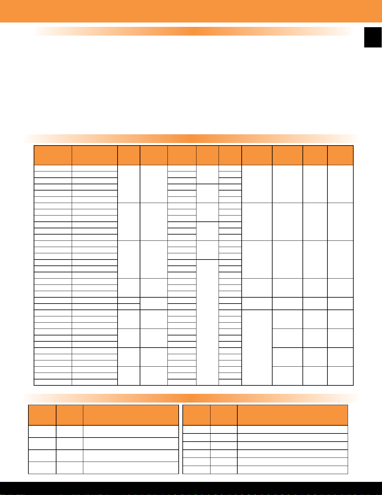
2600 Series Downow Unit Heater
Product Specications
SPECIFICATIONS: The contractor shall furnish and install the 2600 Series electric vertical discharge unit heaters of the size, capacity and voltage specied. Heaters
shall be installed according to the manufacturer’s recommendations and applicable national and local codes.
ELEMENTS: Elements shall consist of Nickel Chromium alloy resistance wire embedded and completely surrounded in Magnesium Oxide, enclosed and swagged into
corrosion resistant sheaths. Corrosion resistant steel ns shall be permanently attached to the sheaths to provide maximum heat transfer to the air stream.
MOTORS: Motors shall be single phase, resilient mounted, totally enclosed, industrial rated with an automatic reset thermal overload protective device. Motors on
heaters up to 20 KW capacity shall be permanently lubricated shaded pole type. Over 20 KW, motors shall be permanent split capacitor type. Motors shall be mounted
out of the main air stream in such a manner as to allow ambient air to be drawn over the motor to reduce motor temperature. Motor shall be separately removable from
beneath the heater without removing the entire heater from mounting bracket.
FAN BLADES: Fan blades shall be heavy-duty individually balanced axial ow type. Fan speed shall not exceed 1570 RPM.
THERMAL OVERLOAD PROTECTION: All heaters shall be equipped with a manual reset thermal cutout which disconnects elements and motor in the event normal
operating temperatures are exceeded.
WIRING: Heaters shall be designed for a single supply circuit with elements, motor and control circuits subdivided and fused to conform with the latest National Electric
Code and OSHA requirements. All three phase heaters shall have balanced phases.
CONTROLS: Heaters shall be controlled by a low voltage wall mounted thermostat. All heaters 25 KW and larger shall be wired for 2 stage operation. 5 KW through 20
KW units are single stage. All heaters shall be equipped with a fan safety device that causes fan to operate after elements are de-energized to purge unit of residual heat.
Standard Models
21
MFG
CATALOG
NUMBER
07157502 F1F2605CA1
07157602 H1H2605CA1 240 20.83
07157702 G1G2605CA1 277 18.05
07157802 F3F2605CA1 208
07157902 H3H2605CA1 240 12.04
07158002 P3P2605CA1 480 6.02
07158202 F1F2607CA1
07158302 H1H2607CA1 240 31.25
07158402 G1G2607CA1 277 27.07
07158502 F3F2607CA1 208
07158602 H3H2607CA1 240 18.06
07158702 P3P2607CA1 480 9.03
07158902 F1F2610CA1
07159002 H1H2610CA1 240 41.66
07159102 G1G2610CA1 277 36.1
07159202 F3F2610CA1 208
07159302 H3H2610CA1 240 24.08
07159402 P3P2610CA1 480 12.04
07159602 F3F2615CA1
07159802 P3P2615CA1 480 18.06
07160002 H3H2620CA1 19.4
07160102 P3P2620CA1 20 480 24.08
07175102 F3F2625CA1
07175302 P3P2625CA1 480 30.1
07175502 F3F2630CA1*
07175702 P3P2630CA1 480 36.12
07175902 F3F2640CA1*
07176102 P3P2640CA1 480 48.16
07176302 F3F2650CA1*
07176502 P3P2650CA1 480 60.21
*Disconnect not available
MFG
MODEL
NUMBER
KW BTUs VOLTS PH AMPS
208
1
5 17065
3
208
1
7.5 25598
3
208
1
10 34130
208 41.68
15 51195
68260
25 85325
30 102390
40 136520
50 170650
240 48.16
208 69.48
3
208 83.37
208 111.17
208 138.96
Field Installed Accessories
24.03
13.89
36.05
20.84
48.07
27.79
CONTROL
VOLTS
24 34 490 75
24 45 560 75
24 26 1200 75
24 39 1200 7507159702 H3H2615CA1 240 36.12
24 52 1200 75
24
TEMP
RISE
24 3300 17507175202 H3H2625CA1 240 60.21
29 3300 17507175602 H3H2630CA1 240 72.25
38 3300 17507176002 H3H2640CA1* 240 96.33
48 3300 17507176402 H3H2650CA1* 240 120.42
CFM
O
F
WT
(LBS)
MFG
CATALOG
NUMBER
06926302 FSW5112 Summer Fan Switch
06911002 TC1602
07177502 A1600 Ceiling Mount Bracket 5-20 KW Models
07177602 A1601 Ceiling Mount Bracket 25-50 KW Models
MFG
MODEL
NUMBER
DESCRIPTION
Wall Mounted Stratication Thermostat
Range - (70
o
F - 140 oF)
MFG
CATALOG
NUMBER
07177902 D1602 Linear Louvered Diffuser 5-20 KW Models
07178002 D1612 Linear Louvered Diffuser 25-50 KW Models
07178102 D1600 Radial Louvered Cone Diffuser 5-20 KW Models
07178202 D1610 Radial Louvered Cone Diffuser 25-50 KW Models
07178302 D1603 Anemostat Diffuser 5-20 KW Models
07178402 D1613 Anemostat Diffuser 25-50 KW Models
MFG
MODEL
NUMBER
DESCRIPTION
Page 23
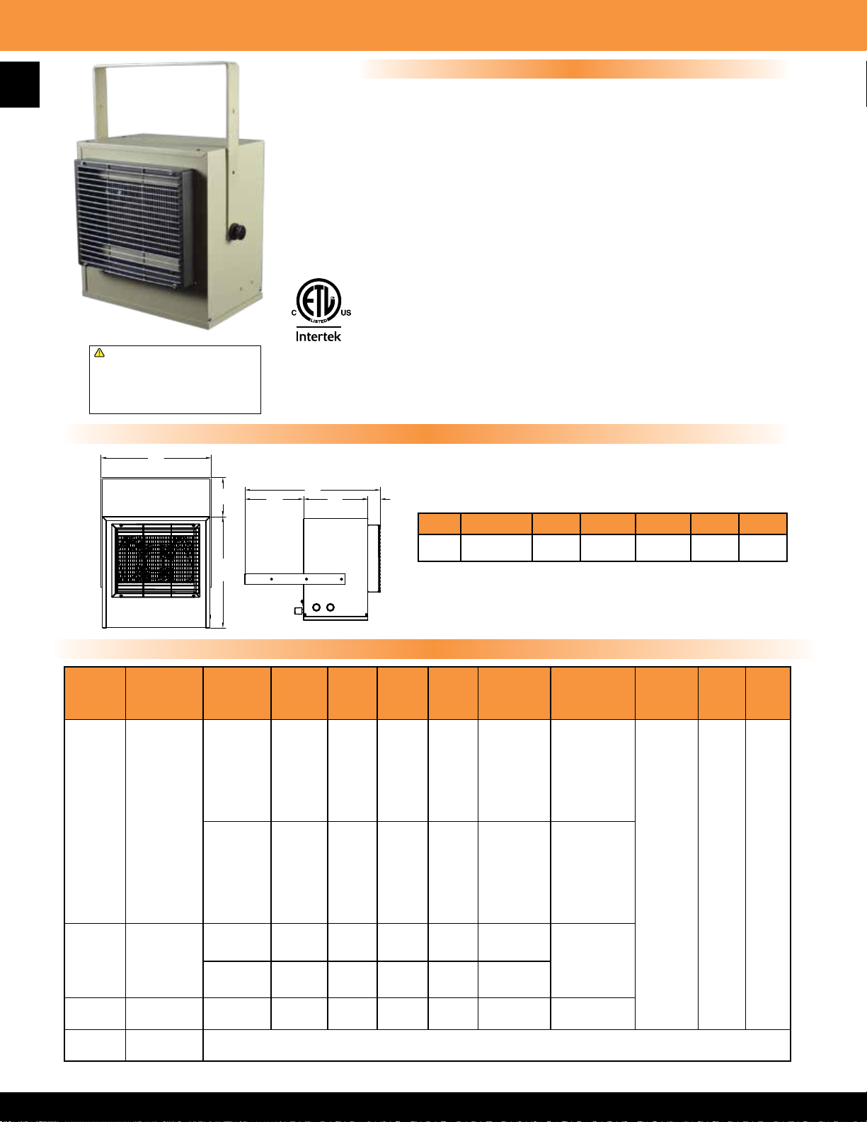
22
5700 Series Conned Space Plenum Rated Heater
!
WARNING: This product can expose you
to chemicals including nickel which is known
to the State of California to cause cancer,
and chromium, which is known to the State
of California to cause birth defects and/or
reproductive harm. For more information go
to www.P65Warnings.ca.gov.
A
Features
• Easily ts between joists for typical installation
• Zero clearance for wall and ceiling mounting as well as
oor mounting with appropriate inlet and outlet clearances
3
• Bracket standard or can be mounted by
⁄8” threaded rod
(eld supplied)
• Automatic reset thermal limit for safety
• 1 Phase model wattage eld changeable from 1874
to 5000 Watts
• 24V control circuit on three phase models with
hydraulic thermostat
• Made in U.S.A
Conforms to ANSI/UL 1995
Certied to CAN/CSA C 22.2 No.236-11
Product Dimensions
MFG
CATALOG
NUMBER
07262402 HF5705T
MFG
MODEL
NUMBER
E
B
D
F
G
A B C D E F G
14.4” 19.4” 14.5” 8.4” 5.1” 9.2” 1.8”
C
Standard Models
WATTS BTUs VOLTS PHASE AMPS TEMP RISE TEMP RANGE
o
5000 17065
4165 14215 17 48
240 1
3332 11365 14 38 oF
2500 8533 10 29
3750 12798
3123 10659 15 36
208 1
2500 8553 12 29 oF (40 oF-120 oF)
1874 6396 9 21
21 57
18 43
F
o
F (40 oF-120 oF)
o
F
o
F
o
F
o
F
AIR
THROW
16' 275 32
CFM
WT.
(LBS)
o
3750 12799 208 3 10.4 43
07262502 H3H5705T
5000 17065 240 3 12 57
07262602 P3P5705T 5000 17065 480 3 6 57 oF (40 oF-110 oF)
07073602 DCS-MT303 Optional Field Installed Disconnect Switch, 30 Amp @ 600Volts
F
o
F
(40 oF-110 oF)
Page 24
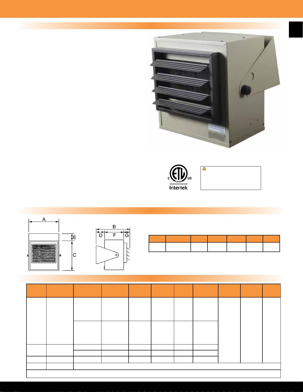
5600 Series Multiple Wattage Fan Forced Unit Heater
Product Specications
CASING & CONSTRUCTION: Fabricated of die formed,
heavy gauge steel and nished with two tone, brown and
beige, durable powder coated paint. Supply air is drawn
through the rear heavy duty expanded steel inlet grill. Heated
air is discharged through front adjustable louvers, which
are spring loaded for individual adjustment. Made in U.S.A.
ELEMENT: Heavy-duty block n element design. The multiple tap
electric connection design allows eld conversion to eight wattage
settings at 208/240-Volt single phase or 240/480 Volt, 3 phase.
Units are available on special order with a specic wattage/
voltage setting.
MOTOR: Motor shall be totally enclosed, permanently lubricated,
all angle industrial rated with thermal overload protection.
WIRING: Wiring to terminal block adjacent to incoming knockout
in accordance with NEC and local codes.
THERMAL OVERLOAD: All heaters shall be equipped with an
automatic reset thermal cutout to shut down the element and
motor circuits if unsafe operating temperatures are exceeded.
CONTROLS: The heater shall have a heavy-duty hydraulic
thermostat (with a temperature range of 40
o
F-110 oF)factory
installed and wired. All controls and wiring shall be in a large
wiring compartment with hinged door for easy access. An optional
disconnect switch shall be available for eld installation.
MOUNTING: Heaters are standard with a three position-
mounting bracket for wall, ceiling or workbench. Heaters
can be mounted for horizontal or vertical discharge.
Note: Minimum mounting height is 6 feet, and minimum
distance from side of heater to nearest wall is 6 inches.
Note: Approved for residential applications.
Front view
!
WARNING: This product can expose you
to chemicals including nickel which is known
to the State of California to cause cancer,
and chromium, which is known to the State
of California to cause birth defects and/or
reproductive harm. For more information go
to www.P65Warnings.ca.gov.
23
Product Dimensions
A B C D E F G
14” 12
11
⁄16” 14” 1 9⁄16” 1 9⁄16” 9” 2 3⁄4”
Standard Models
MFG
CATALOG
NUMBER
07072802 HF5605T
07072902 H3H5605T
07073002 P3P5605T 5000 17065 480 3 6 57
07073602 DCS-MT303 Optional Field Installed Disconnect Switch, 30 Amp @ 600Volts
MFG
MODEL
NUMBER
WATTS BTUs VOLTS PHASE AMPS
5000 17065
4165 14215 17 48
3332 11365 14 38
240 1
21 57
TEMP
RISE
2500 8533 10 29 oF
3750 12798
3123 10659 15 36
2500 8553 12 29
208 1
18 43
1874 6396 9 21 oF
3750 12799 208 3 10.4 43
5000 17065 240 3 12 57
For 24V control on single phase models delete "T" sufx
AIR
THROW
o
F
o
F
o
F
o
F
o
F
o
F
o
F
o
F
o
F
16' 275 32
CFM
WT.
(LBS)
Page 25
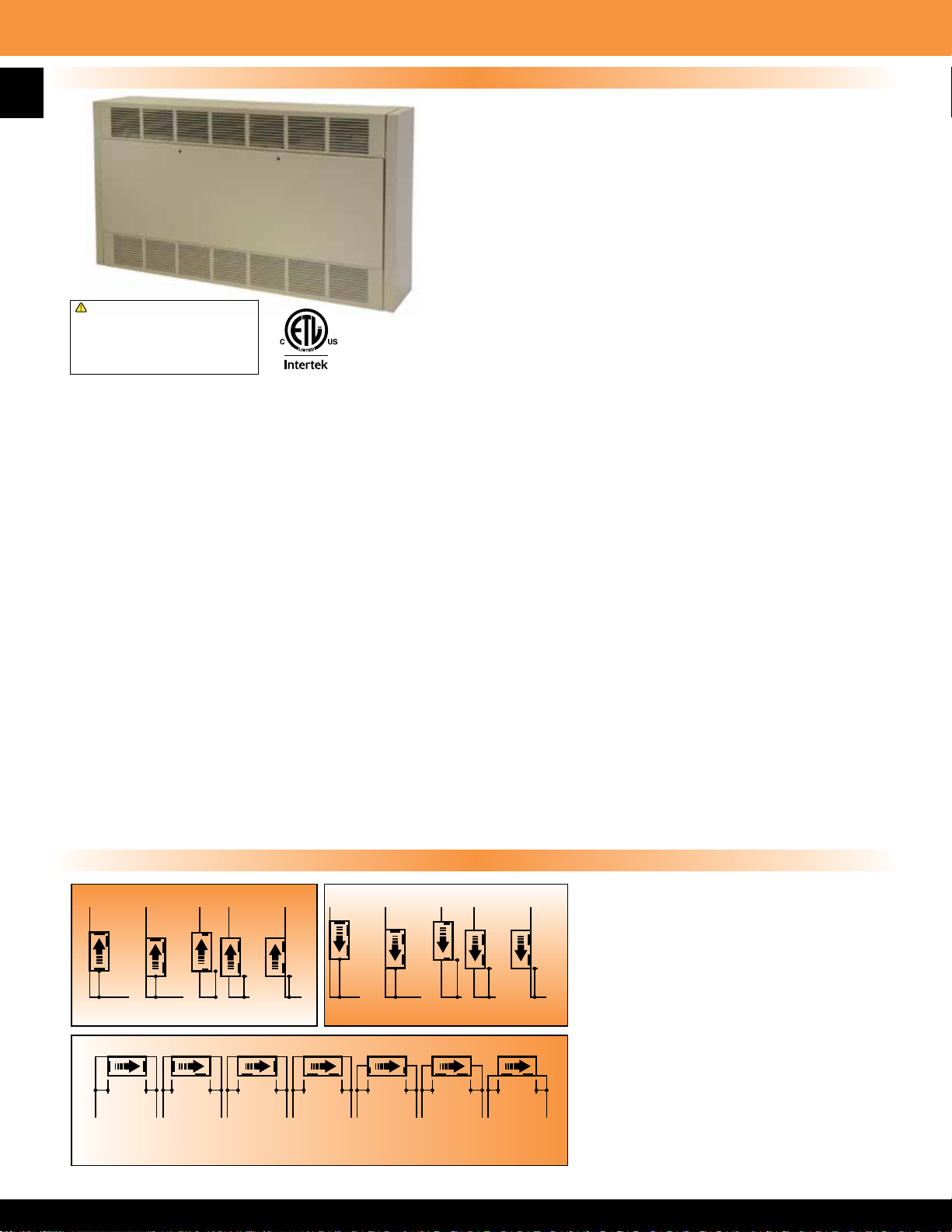
24
“T” Series Multiple Angle Cabinet Unit Heater
Product Specications
The electric cabinet unit heater is designed for mounting in any
position, fully recessed, semi-recessed or surface mounted. All
capacities, voltages, physical sizes, grille arrangements and options
shall be as specied on the plans. All units must be eld convertible
to the following:
1. For control by a eld supplied remote thermostat.
2. Load management control with an external dry switch.
When closed unit operates under control of either
the internal or the external thermostat. When open, unit
turns off.
!
WARNING: This product can expose you
to chemicals including nickel which is known
to the State of California to cause cancer,
and chromium, which is known to the State
of California to cause birth defects and/or
reproductive harm. For more information go
to www.P65Warnings.ca.gov.
motor-blower assembly, lters and all internal components. The grill conguration must be easily eld convertible to any air ow
conguration (by removal of no more than four fasteners). The cabinet shall have a textured nish of two coats of powder coat
epoxy and be suitable for use with optional kick space base. Made in U.S.A.
HEATING ELEMENTS: The heating elements shall be warranted for 1 year and shall be non-glowing design consisting of special
high temperature resistance wire enclosed in an incoloy sheath to which steel ns are furnace brazed. The heating elements shall
be located directly in front of the blower discharge air for uniform heating. They shall be mounted with a single anchor at one end
to minimize effects of thermal expansion and contraction.
3. Any grille arrangement.
CABINET & CONSTRUCTION: The cabinet shall be constructed
of heavy duty 16 gauge Zinc coated steel. The heater shall have a
removable front door for easy access to the control panel, elements,
SAFETY CUTOUT: Thermal safety limits shall be built into the system to automatically shut off heater in event of overheating due
to any cause. The safety cutouts shall be of two types:
A. The primary limit shall be an automatic capillary type to sense the heat along the full length of the heating elements. It shall
de-energize the heaters by opening the coil circuit on the heating contactors.
B. The secondary limit shall be a manual reset thermal device to interrupt power to the heating elements.
MOTOR AND BLOWER ASSEMBLY: The motors and blowers shall be direct drive and resiliently mounted on rigid heavy gauge
frame for quiet operation and long life. The motor shall be two-speed, shaded pole type, rated for the voltage (480 to 600 Volts
are single speed only). Each shall have built-in automatic reset overload protection and are life time lubricated. The motor shall be
vented and mounted in the air stream to provide maximum cooling of the motor.
HIGH AND LOW HEAT RANGES: All units will be supplied as standard with a switch for selecting full heat at high fan speed or
reduced heat at low fan speed (On 480 & 600 Volt units the switch changes the heat but not the fan speed).
OVER CURRENT PROTECTION: Circuit breakers shall be provided for branch circuit protection where required by NEC. Circuit
breakers are optional on all other heaters.
TEMPERATURE CONTROL: Integral factory installed thermostat shall be tamper resistant, linear capillary type. Optional setback
thermostat available.
Mounting Congurations
Up Flow Down Flow
A
C
B
A
D D D
A
B
C
A
D D D
NOTE: Semi-recessed units are to be
recessed at a maximum of 3
1
⁄2” unless
grill conguration is front in and front out.
MOUNTING CLEARANCES: Proper
W W
Y Y Y Z X X XZ
Semi
Recessed
Completely
Recessed
Semi
Recessed
Completely
Recessed
clearances are indicated for each
mounting conguration on all positions.
Minimum clearance from side of unit
to the wall is zero inches. Mounting
inches are provided in the back of the
A A
W
B
W
Z Z
Ceiling Mounted
KEY: W = 6” minimum, X = 12” minimum, Y = 0” or greater, Z = 24” minimum
C
Y
D D D
W
Z
Semi
Recessed
YYY
Completely
Recessed
cabinet, accessible through the blower
XXXX
compartment, if necessary, remove blower
deck if additional mounting screws or bolts
are desired. Blower deck may be slipped
forward by loosening four screws at the
front to provide access to mounting holes.
Page 26
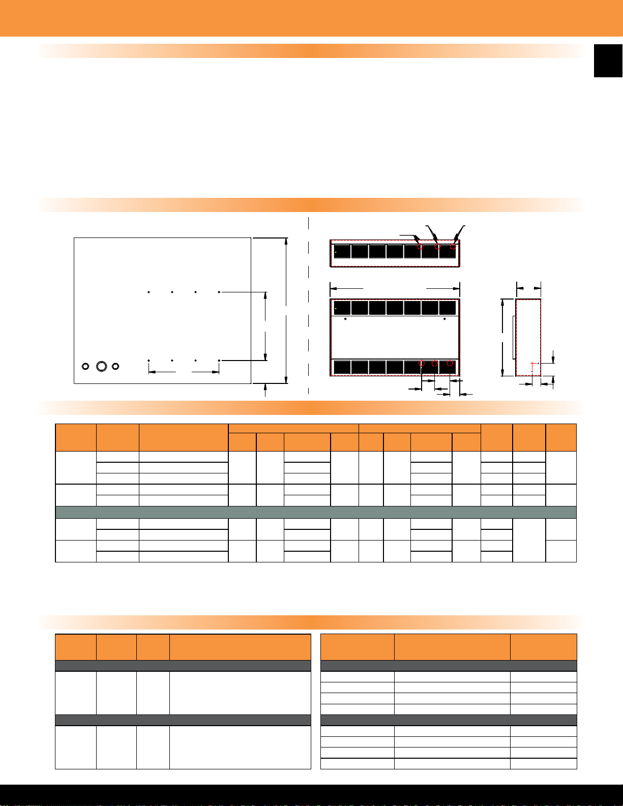
“T” Series Multiple Angle Cabinet Unit Heater
Product Features (2-24 KW; All Voltages)
• For commercial and institutional application such as
stores, schools, ofces, transportation terminals, churches,
or entranceways
• Wall or ceiling mount; surface, semi-recessed or
fully recessed
• (8) air inlet and outlet congurations
• Capacities from 2-24 KW with 230 to 1,000 CFM
• Motors are two speed, shaded pole, resilient mounted,
direct drive. High/low heat and blower speed offer versatility
• ETL Listed
• Beige powder coated nish
Product Dimensions
Mounting Hole Locations
(Back View of Unit)
• Choice of eight standard control options include unit or wall
mounted 120 or 24V thermostats, with or without built-in
control transformers, setback thermostat option
• Industrial type nned tubular elements
• Easily removable fan and element decks for simplied
maintenance
• Full length thermal protection
• Limited warranty-one year
• Optional locking front cover
1/2”, 3/4” Conduit
1/2”, 3/4” Conduit
1/2”, 1-1/2” Conduit
25
1/4” Dia. Mounting Holes
11-11/16”
12”
Knockouts
24”
44”
56”
4-1/16”
Stocked Models & Features
HEATER
LENGTH
33”
46”
33”
46”
MFG
CATALOG
NUMBER
06671402 T33D052033B30D0F
06670802 T33D054833B30D0F 7.8 4.6 480 3
06671902 T46D102433B30D0F
06672002 T46D104833B30D0F 15.4 8.1 480 3
04736202 6333D053834B30D0F1
04736302 6333D054134B30D0F1 6.97 4.18 415
04736402 6346D103834B30D0F1
04736502 6346D104134B30D0F1 13.94 8.36 415
*Factory wired for 3-phase, eld convertible to 1-phase.
• 1 / 3 phase eld convertible with 24 Volt control circuit.
• Disconnect switch, dust lter, & high low operation.
• Built-in thermostat and eld convertible for remote thermostat.
MFG
CATALOG
NUMBER
04415602 DC-33 33"
04415702 DC-46 46"
04415802 DC-66 66"
04415902 DC-79 79"
04537802 TF-33 33"
04537902 TF-46 46"
04538002 TF-66 66"
04538102 TF-79 79"
MFG
MODEL
NUMBER
RECESSING TRIM FRAMES
MFG
MODEL
NUMBER
SIZE DESCRIPTION
DUCT COLLAR
The same model is used for the inlet or
If duct collars are required for both inlet &
outlet then 2 must be ordered.
Recessing Trim Frames should be ordered
to "trim-out" any recessed or semi-recessed
KW BTUs AMPS CFM KW BTUs AMPS CFM
5 17065
10 34130
5 17065
10 34130
outlet.
installation.
3/5 KW = 33”
6/10 KW = 46”
25”
2-3/8”
HIGH LOW
25.0 / 17.6
250 3 10239
43.6 / 30.7
International Models
7.6
15.2
500 6 20478
250 3 10239
500 6 20478
Accessories
MFG
CATALOG
NUMBER
Fresh Air Make-Up Intake Flange & Kickbase
07715802 FAM33 33"
07715902 FAM46 46"
07716002 FAM66 66"
07716102 FAM79 79"
Kickbase (Pedestal) ONLY
07715402 KB33 33"
07715502 KB46 46"
07715602 KB66 66"
07715702 KB79 79"
15.4 / 9.2
26.9 / 16.2
4.56
9.12
MODEL
NUMBER
MFG
2-3/4”
3-3/8”
230
460
230
460
9“
25”
1-9/16”
VOLTS PHASE
208 1-3*
240 1-3*
380
3
(4-Wire)
380
SIZE
3“
WT.
(LBS)
9906671502 T33D052433B30D0F 21.8 / 15.4 13.5 / 8.2 240 1-3*
130
99
130
Page 27
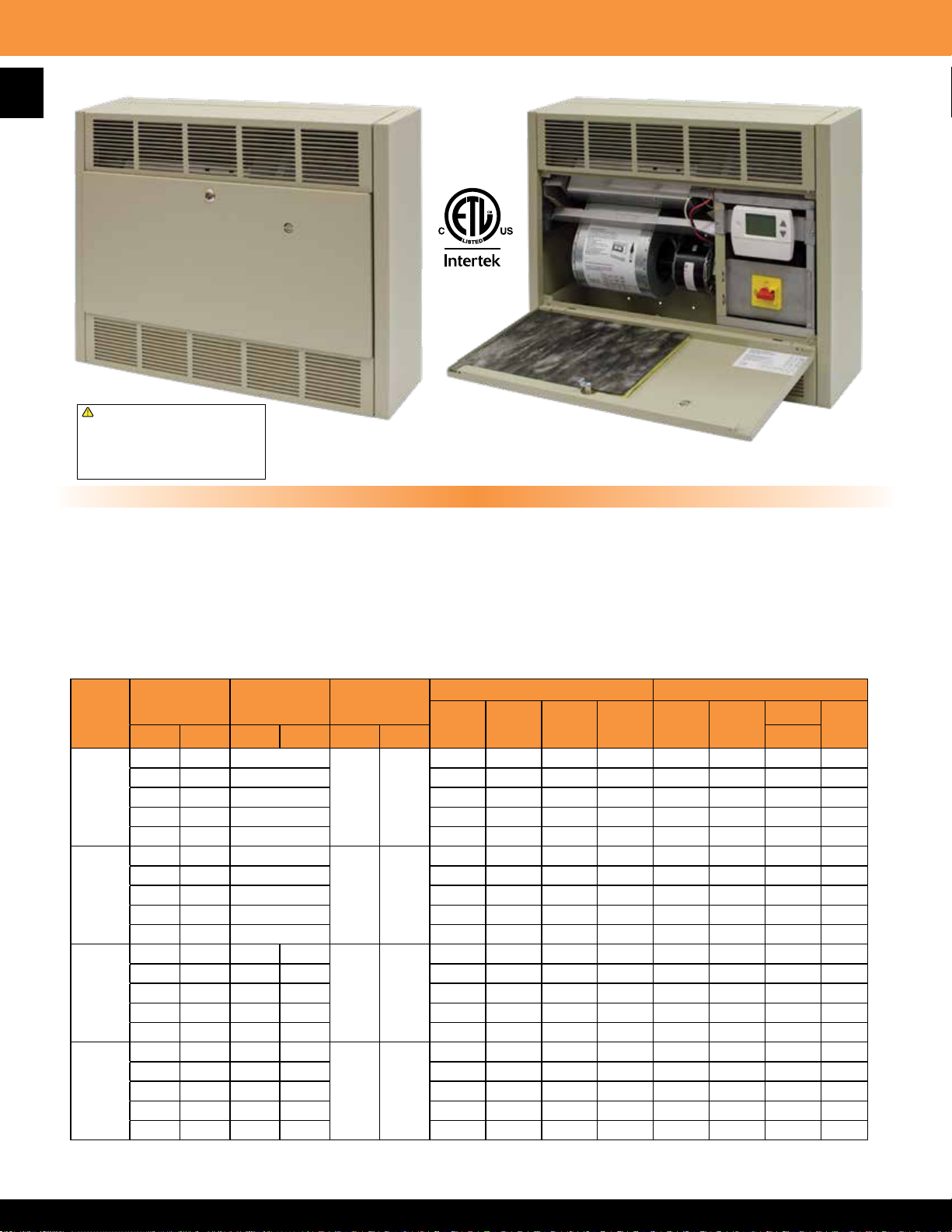
26
“T” Series Multiple Angle Cabinet Unit Heater
!
WARNING: This product can expose you
to chemicals including nickel which is known
to the State of California to cause cancer,
and chromium, which is known to the State
of California to cause birth defects and/or
reproductive harm. For more information go
to www.P65Warnings.ca.gov.
Locking Cover Option SD Setback Thermostat Option
T SD Series Features
• Multi-stage operation-only using the heat you need, when you need it
• 65 second delay between stages
• Sensor has a 94 degree angular range and a 16’ linear range
• 50-90 degree thermostat range
• Setback capability up to 12 degrees - eld set. Achieves energy savings when area not occupied and heat not needed
• Purge cycle of 90 seconds allows residual heat to be exhausted from heater
• Factory pre-programmed for system type/voltage
• Easy steps to set thermostat and setback feature
• Occupancy sensor defaults to economy mode after one hour, up to 12 degree setback
• Sensor has a 94 degree angular range and a 16’ linear range
1-PHASE UNITS - AMPS (HIGH) 3-PHASE UNITS - AMPS (HIGH)
208V 240V 277V 600V 208V 240V
10.6 9.3 8.12 3.8 9.2 8.1 4.1 3.3
21.1 18.6 16 7.46 18.7 16.2 8.1 6.5
31.8 27.9 24.1 11.3 27.6 24.3 12.3 9.8
42.3 37.1 32 14.9 36.7 32.3 16.2 13
480V
LENGTH
33”
46”
66”
79”
KW
High Low Left Right High Low 3-WIRE
2 1 2
3 2 3 15.4 13.5 11.7 5.5 9.2 8.1 4.1 3.4
4 2 4 20.2 16.7 15.3 7.2 13.4 11.8 6 6.22
5 3 5 25 21.8 19 8 17.6 15.4 7.8 5.5
6 3 6 29.9 26 22.6 10.5 17.6 15.4 7.8 6.3
4 2 2
6 4 3 30.8 26.9 23.1 10.79 18.4 16.2 8.1 6.5
8 4 4 40.4 35.2 30.5 14.12 26.7 23.4 11.7 9.4
10 6 5 50 43.6 37.7 17.5 35.1 30.7 15.4 12.3
12 6 6 59.6 51.9 44.9 20.8 35.1 30.7 15.4 12.3
6 3 2 2
9 6 3 3 46.2 40.4 35 16.3 27.6 24.3 12.3 9.9
12 6 4 4 60.6 52.9 45.8 21.3 40.1 35.2 17.7 15.6
15 9 5 5 75 65.4 56.7 25.5 52.6 46.1 23.1 15.7
18 9 6 6 89.4 77.9 67.5 31.3 52.6 46.1 23.1 18.5
8 4 2 2
12 8 3 3 61.5 53.8 46.5 21.6 36.7 32.3 16.2 13
16 8 4 4 80.7 70.5 61 28.2 53.4 46.8 23.5 18.8
20 12 5 5 NA 87.1 75.4 34.9 70.1 61.4 30.7 24.6
24 12 6 6 NA NA 89.8 41.6 70.1 61.4 30.7 24.6
Elements per
Heat Deck
CFM
250 230
500 460
750 690
1000 920
600V
Page 28
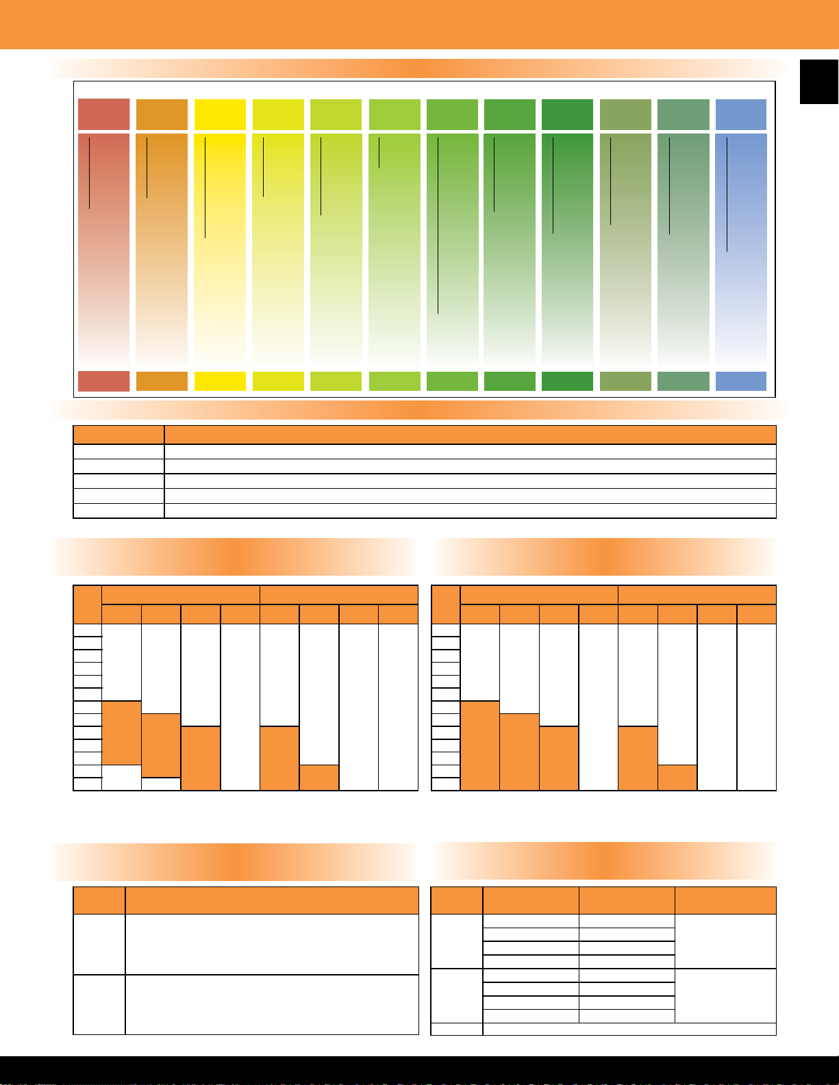
HOW TO DESIGNATE A MODEL:
“T” Series Multiple Angle Cabinet Unit Heater
Custom Specied Models
T 46 D 08 24 1 2 B3 S D O F
27
Series Number
Step 1 Step 2 Step 3 Step 4 Step 5 Step 6 Step 7 Step 8 Step 9 Step 10 Step 11 Step 12
Cabinet Size
Air Flow Configuration
33 = 33” 46 = 46” 66 = 66” 79 = 79”
A = Bottom in / Top out B = Bottom in / Front out
Element KW
Element Voltage
2KW through 24KW
D = Front in / Front out
20 = 208V 24 = 240V 27 = 277V
See model chart for length and KW options.
C = Front in / Top out
Phase
41 = 415V 48 = 480V 57 = 600V
1 = Single Phase 3 = Three Phase
2, 3, or 4
SD = Setback
B3, B4, B5, B6
Control Options
Summer Fan Switch
(see control options chart)
S = Included O = Not Included
Number of Wires in Electrical Service
Disconnect Option
C = Circuit Breaker D = Disconnect Switch
Motor Fusing Option
O = None
M = Required O = Not Required
Control Option (Step 8 on Model Designator)
SUFFIX DESCRIPTION
B3 In-Built 1-Stage Stat and Relays which are operated by an internal 24 Volt source. (40 oF-110 oF)
B4* In-Built 1-Stage Stat and Relays which are operated by an internal 120 Volt source. (40 oF-110 oF)
B5 In-Built 2-Stage Stat & Relays which are operated by an internal 24 Volt source. (40 oF-120 oF)
B6* In-Built 2-Stage Stat and Relays which are operated by an internal 120 Volt source. (40 oF-120 oF)
SD Setback Thermostat
*Motor fusing included for units with 120V internal or external control source.
Disconnect Option “C” Circuit Breaker
(Step 10 on Model Designator)
Disconnect Option “D” Disconnect Switch
(Step 10 on Model Designator)
L = Locking Front Cover
Disposable Filter Option
F = Required O = Not Required
KW
2
3
4
5
6
8
10
12
15
16
18
20
24 N/A
Circuit breakers shown in shaded areas are required by NEC because unit
exceeds 48 Amps, all others listed are optional unless otherwise stated.
SINGLE PHASE THREE PHASE
208V 240V 277V 600V 208V 240V 480V 600V
available
available
available
required
required
N/A required
required
Fan Switch & Motor Fusing
(Steps 9 & 11 on Model Designator)
SUFFIX DESCRIPTION
S Summer Fan Switch
M Motor Fusing (when not provided by control option)
available
available
required
available
available
KW
2
3
4
5
6
8
10
12
available
15
16
18
20
24
Disconnect option is not available on heaters with circuit breaker.
SINGLE PHASE THREE PHASE
208V 240V 277V 600V 208V 240V 480V 600V
option "C"
circuit breaker
available without
circuit breaker
available without
N/A
N/A
"C"
option "C"
available without
circuit breaker option
N/A
available without circuit breaker
option "C"
"C"
available without
circuit breaker option
available without circuit
N/A
Filter Option
(Step 12 on Model Designator)
SUFFIX SIZE
33" 1
F
W
L Locking Cover
46" 1
66" 2
79" 2
33" 1
46" 1
66" 2
79" 2
Qty.
REQ'D
option "C"
breaker option "C"
available without circuit breaker
N/A
FILTER
TYPE
Replaceable
Washable
option "C"
available without circuit breaker
Page 29
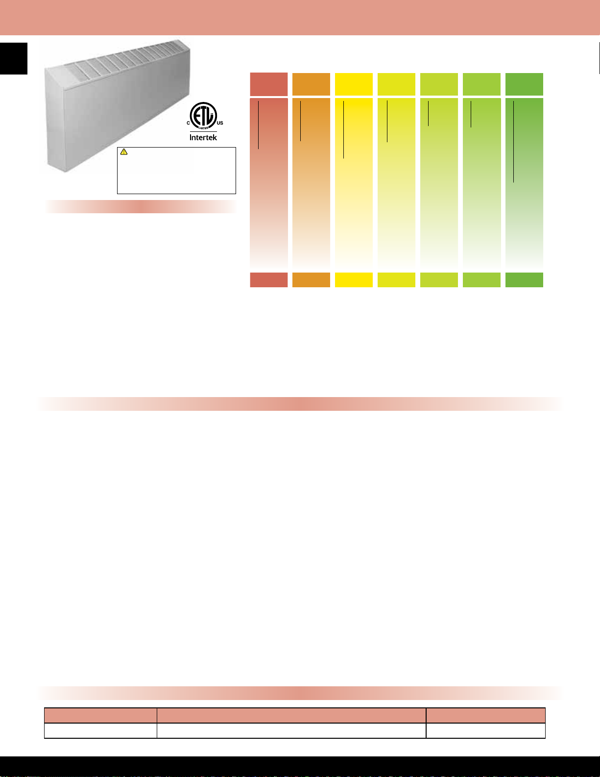
28
HOW TO DESIGNATE A MODEL:
8500 Series Commercial Slope Top Wall Convector
!
WARNING: This product can expose you
to chemicals including nickel which is known
to the State of California to cause cancer,
and chromium, which is known to the State
of California to cause birth defects and/or
reproductive harm. For more information go
to www.P65Warnings.ca.gov.
Features
• Front In/Top Out or Bottom In/Top Out
air pattern
• 16 gauge steel housing powder coated
with beige nish
• Tubular pre-wired wireway with
40 Amp capacity
• Connection boxes for right or left hand
1
wiring with combination
⁄2” - 3⁄4” knockouts
at back and bottom
• Stainless steel element with Aluminum ns
• Linear limit type thermal overload with
automatic reset
• Limited by max amp draw of 25 Amps
(with no controls)
• Made in U.S.A.
B=Bottom in F=Front in
DST1
Factory Installed Options
85 2 5 125 H B
Series Number
Step 1 Step 2 Step 3 Step 4 Step 5 Step 6 Step 7
Cabinet Size
Unit Length (feet)
2, 3, 4, 5, 6, 7, 8, 9, 0 (enter 0 for 10’)
1=10”H x 3”D 2=14“H x 5”D 3=20”H x 5”D
Watts per Foot
8510= 250 max 8520=500 max 8530=750 max
Voltage
E = 120V F = 208V G = 277V H=240V
Air Flow
• Pencil proof louver design
• Custom colors available, consult factory
Note: Not for residential applications
Note: Disconnect limits amperage to 16 Amps
(see control option chart)
blank=none T1 or T2=Thermostat
R1, R2, or R9=Relay DS=Disconnect
CABINET:
Rugged 16 gauge front cover with discharge louvers in sloped top design. Pencil proof louver design for
sloped outlet and front inlet grill. The nish shall be durable powder coated paint. Air ow available as
bottom in - top out, or front in - top out.
ELEMENT:
All steel high mass element construction with Nickel-Chromium resistance wire embedded in compacted
efcient dielectric to ensure proper heat transfer. Aluminum ns mechanically bonded to steel tube allows
for increased surface area and even heat transfer.
LIMIT CONTROLS:
Automatic reset hydraulic thermal overload covers full length of heating element and shuts down heater
when safe operating temperatures are exceeded.
WIRING:
Connection boxes in either end with ½ inch to ¾ inch knockouts at back and bottom. Tubular prewired wire
way with 40 Amp capacity.
CONTROLS:
Optional built in tamper resistant thermostat and disconnect.
MOUNTING:
Heater shall be surface mounted to wall or mullion. Bottom inlet units must be mounted a minimum of 4
inches above nished oor front inlet.
Product Specications
Voltage & Wattage Specication
Voltage Standard Wattages Per Foot Heater Lengths
120-277 100,125,150,165,187,200,250 2’ through 10’
Page 30
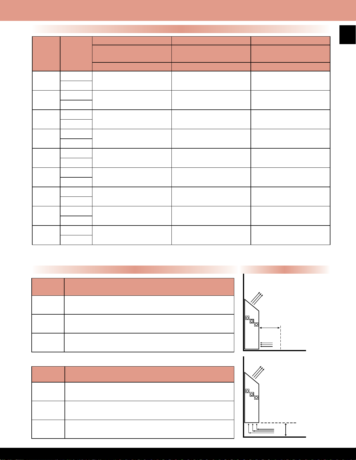
8500 Series Commercial Slope Top Wall Convector
Standard Models
8510 SERIES 8520 SERIES 8530 SERIES
H E AT E R
LENGTH
2’
3’
4’
5’
6’
7’
8’
9’
10’ *
Note: All models qualify for international use
Note: Products listed in this section are custom built and subject to 100% cancellation/restocking charges.
*120V not available in 10’ units
WATTS
per
FOOT
100-250
333-750
100-250
333-750
100-250
333-750
100-250
333-750
100-250
333-750
100-250
333-750
100-250
333-750
100-250
333-750
100-250
333-750
3” Depth x 10” Height
Max watts per foot = 250
MFG MODEL NUMBER MFG MODEL NUMBER MFG MODEL NUMBER
8512 8522 8532
8513 8523 8533
8514 8524 8534
8515 8525 8535
8516 8526 8536
8517 8527 8537
8518 8528 8538
8519 8529 8539
8510 8520 8530
5” Depth x 14” Height
Max watts per foot = 500
29
5” Depth x 20” Heigh
Max watts per foot = 750
SUFFIX DESCRIPTION
T1
T2
DS Double Pole Disconnect Switch, 16 Amp
Note: Due to size limitations, 8510 Series convectors can only have thermostats as In-Built options
SUFFIX DESCRIPTION
R1 DPST Relay, 30 Amps, up to 277V, 120V coil
R2 SPST Relay, 18 Amps @ 277V (max), 24V coil
R9
In-Built Tamper Proof, Single Pole, Bimetal Thermostat
(0°-110°F temp. range, 25 Amp)
In-Built Tamper Proof, Double Pole, Bimetal Thermostat
(0°-110°F temp. range, 25 Amp)
24V Transformer and SPST Relay
22 Amps @ 240V, 18 Amps @ 277V (max), 24V coil
(cannot be used in conjunction with T2 option)
Mounting/Air Flow OptionsIn-Built Control Options
AIR FLOW
MINIMUM 6” IN
FRONT OF HEATER
IS REQUIRED
AIR FLOW
AIR FLOW
MINIMUM 4” ABOVE
FINISHED FLOOR
REQUIRED
AIR FLOW
FRONT IN
TOP OUT
BOTTOM IN
TOP OUT
Page 31
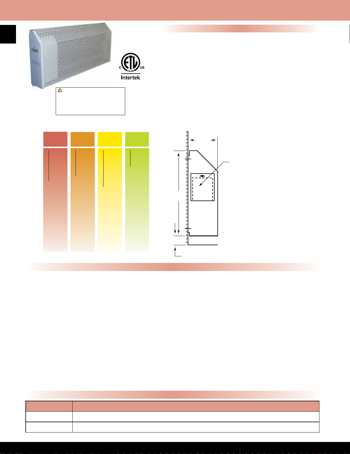
30
HOW TO DESIGNATE A MODEL:
left side view
8800 Series Institutional Wall Convector
!
WARNING: This product can expose you
to chemicals including nickel which is known
to the State of California to cause cancer,
and chromium, which is known to the State
of California to cause birth defects and/or
reproductive harm. For more information go
to www.P65Warnings.ca.gov.
Features
• Single phase heaters available in all common voltages from
120V to 600V
• 11 gauge perforated steel housing powder coated with
textured ivory nish
• Tamper proof left side control panel houses built-in single
pole thermostat - range 40°F-110°F and disconnect switch.
Thermostat on 120V-277V units is line voltage and low
voltage (24V) on 346V-600V units
• Linear limit type thermal overload with automatic reset
• Tamper proof fasteners
• Stainless steel element with Aluminum ns
• Made in U.S.A.
Note: Not for residential applications
Left Side View
85 2 5 H
Series Number
CABINET:
Institutional enclosure 11 gauge perforated steel with sloped top design. Heavy duty end caps welded to the enclosure. Control
compartment for housing thermostat and disconnect switch is accessible by use of security type fastener. The entire enclosure is
protected by epoxy powder coated paint nish.
ELEMENT:
All steel high mass element construction with Nickel-Chromium resistance wire embedded in compacted efcient dielectric to
ensure proper heat transfer. Aluminum ns mechanically bonded to steel tube allows for increased surface area and even heat
transfer.
LIMIT CONTROLS:
Automatic reset hydraulic thermal overload covers full length of heating element and shuts down heater when safe operating
temperatures are exceeded.
WIRING:
Wiring connections shall be made in left end of cabinet enclosure. Wiring must enter into control enclosure behind perforated steel
grill.
CONTROLS:
All controls are accessible only through control enclosure door. Security type fasteners restrict access to controls. Built in thermostat
and disconnect switch with manual adjustment are located in control enclosure.
Cabinet Size
Unit Length (feet)
2, 3, 4, 5, 6, 7, 8, 9, 0 (enter 0 for 10’)
Voltage
18.00”
E = 120V F = 208V G = 277V H=240V
Product Specications
5.00”
ACCESS DOOR
NOTE:
Allow 12 inch
clearance on left
end of unit and 4”
to the floor.
FLOOR
4.00” Minimum
Optional In-Built Controls
SUFFIX DESCRIPTION
T2 Tamperproof, Hydraulic, Double pole In-Built thermostat range 40°-110°F, 25 Amp
24V* 24 Volt In-Built single pole thermostat for 120V 208V, 240V & 277V models. 40°-110°F
*Not available on international models
Page 32

8800 Series Institutional Wall Convector
Standard Models
MFG CATALOG
NUMBER
08990002 E8801050
08990602 F8801050 208 2.404
08991202 H8801050 240 2.083
08991802 G8801050 277 1.805
08992402 L8801050 346 1.445
08993002 P8801050 480 1.042
08993602 U8801050 600 0.833
08990102 E8802075
08990702 F8802075 208 3.606
08991302 H8802075 240 3.125
08991902 G8802075 277 2.708
08992502 L8802075 346 2.168
08993102 P8802075 480 1.563
08993702 U8802075 600 1.25
08990202 E8803100
08990802 F8803100 208 4.808
08991402 H8803100 240 4.167
08992002 G8803100 277 3.610
08992602 L8803100 346 2.890
08993202 P8803100 480 2.083
08993802 U8803100 600 1.667
08990302 E8804125
08990902 F8804125 208 6.010
08991502 H8804125 240 5.208
08992102 G8804125 277 4.513
08992702 L8804125 346 3.613
08993302 P8804125 480 2.604
08993902 U8804125 600 2.083
08990402 E8805150
08991002 F8805150 208 7.212
08991602 H8805150 240 6.25
08992202 G8805150 277 5.415
08992802 L8805150 346 4.335
08993402 P8805150 480 3.125
08994002 U8805150 600 2.5
08990502 E8806200
08991102 F8806200 208 9.615
08991702 H8806200 240 8.333
08992302 G8806200 277 7.220
08992902 L8806200 346 5.780
08993502 P8806200 480 4.167
08994102 U8806200 600 3.333
MFG MODEL
NUMBER
WATTS BTU’S VOLTS AMPS
120 4.167
500 1706
120 6.25
750 2560
120 8.333
1000 3413
120 10.417
1250 4266
120 12.5
1500 5120
120 16.667
2000 6826
31
LENGTH
(IN.)
18
28
36
48
60
72
International Models
MFG CATALOG
NUMBER
09841402 M8801050i
09841502 H8801050i 240 2.1
09841602 M8802075i
09841702 H8802075i 240 3.1
09841802 M8803100i
09841902 H8803100i 240 4.2
09842002 M8804125i
09842102 H8804125i 240 5.2
09842202 M8805150i
09842302 H8805150i 240 6.3
09842402 M8806200i
09842502 H8806200i 240 8.3
MFG MODEL
NUMBER
WATTS BTU’S VOLTS AMPS
500 1706
750 2560
1000 3413
1250 4266
1500 5120
2000 6826
220 2.3
220 3.4
220 4.5
220 5.7
220 6.8
220 9.1
LENGTH
(IN.)
18
28
36
48
60
72
Page 33

32
HOW TO DESIGNATE A MODEL:
Series Number
(See control option chart)
4100 Series Recessed Commercial Wall Convector
Features
• Front In / Front Out air pattern
• 16 gauge steel housing powder coated with textured
beige nish
• Tubular pre-wired wireway with 40 Amp capacity
• Connection boxes for right or left hand wiring with
1
⁄2” - 3⁄4” knockouts at back and bottom
!
WARNING: This product can expose you
to chemicals including nickel which is known
to the State of California to cause cancer,
and chromium, which is known to the State
of California to cause birth defects and/or
reproductive harm. For more information go
to www.P65Warnings.ca.gov.
combination
• Steel heating element with steel ns
• Linear limit thermal overload with automatic reset
• Recess trim frame included
• Custom colors available, contact factory
• Made in U.S.A.
Note: Not for residential applications
CABINET:
4100 series casing shall be of square design with front inlet and outlet grills suitable for recess installation. The cabinet is
fabricated from 16 gauge cold rolled steel and nished with powder coated baked enamel. Junction boxes are available for left
or right wiring and connected by pre-wired 40 Amp capacity wireway.
M41 25 F 48
Cabinet Size
25=11”H x 4”D 45=20”H x 5”D
Product Specications
Voltage/Phase
H=240V, 1 Phase J=208V, 3 Phase
F=208V, 1 Phase G=277V, 1 Phase
K=240V, 3 Phase
Unit Length (Inches)
24, 36, 48, 60, or 72
1000
Total Wattage
T
Blank=None
Control Option
T or T2=Thermostat R, R2, or R9=Relay
ELEMENT:
All steel high mass element construction with Nickel-Chromium resistance wire embedded in compacted efcient dielectric to
ensure proper heat transfer. Aluminum ns mechanically bonded to steel tube allows for increased surface area and even heat
transfer.
LIMIT CONTROLS:
Automatic reset hydraulic thermal overload covers full length of heating element and shuts down heater when safe operating
temperatures are exceeded.
WIRING:
Wiring connections shall be made in left end of cabinet enclosure. Wiring must enter into
control enclosure behind perforated steel grill.
CONTROLS:
All controls are accessible only through control enclosure door. Security type fasteners restrict access to controls. Built in
thermostat with manual adjustment are located in control enclosure.
Page 34

LENGTH
(IN.)
4100 Series Recessed Commercial Wall Convector
M4125 Dimensions - Cabinet Sizes 4” Deep x 11” High
LENGTH
(IN.)
24 20
36 33
48 39
60 49
72 56
WT.
(LBS)
WATTS per FOOT
AVAILABLE
WT.
(LBS)
M4145 Dimensions - Cabinet Sizes 5” Deep x 20” High
VOLTS
AVAILABLE
WATTS per FOOT
AVAILABLE
187
250
333
PH
LENGTH
(IN.)
VOLTS AVAILABLE PH
208
240
277
WT.
(LBS)
WATTS per FOOT
AVAILABLE
1
VOLTS
AVAILABLE
33
PH
24 45
36 53 36 60
48 63 1 48 71 1
60 77 60 87
72 92 72 106
24 47
36 57 36 60
48 67 1 48 71 3
60 82 60 87
72 100 72 106
Note: Products listed in this section are custom built and subject to 100% cancellation/restocking charges
187
250
333
500
666
208
240
277
208
240
277
24 49
24 49
750
500
666
750
208
240
277
208
240
In-Built Control Options for Single Phase Units
SUFFIX DESCRIPTION
T In-Built Tamper Proof, Single Pole, Hydraulic Thermostat - 40°-110°F temp. range, 25 Amps
T2 In-Built Tamper Proof, Double Pole, Hydraulic Thermostat - 40°-110°F temp. range, 25 Amps
R DPST Relay, 30 Amps, up to 277V, 120V coil
R2 SPST Relay, 18 Amps @ 277V (max), 24V coil
R9 24V Transformer and SPST Relay, 22 Amps @24V, 18 Amps @ 277V (max), 24V coil
Note: No In-Built control options for 3 phase models
UNIT LENGTH MFG MODEL 4125 MFG MODEL 4145
12” MSE4120-12 MSE4140-12
Note: Control section required when relay is ordered
UNIT LENGTH MFG MODEL 4125 MFG MODEL 4145
24” MS4122 MS4142
36” MS4123 MS4143
48” MS4124 MS4144
60” MS4125 MS4145
72” MS4126 MS4146
12” Control Section
Solid Back Panel
Page 35

34
!
WARNING: This product can expose you
to chemicals including nickel which is known
to the State of California to cause cancer,
and chromium, which is known to the State
of California to cause birth defects and/or
reproductive harm. For more information go
to www.P65Warnings.ca.gov.
3000 Series Fan Forced Ceiling Heater
Standard Models
WHITE
MFG
CATALOG
NUMBER
09488202 E3035DWBW 750 or 1500 5120 120 13
09488302 E3038DWBW 900 or 1800 6143 120 15
09488802 H3032DWBW 750 or 1000 - 1500 or 2000 6826 208 / 240 8
09489002 G3032DWBW 2000 6826 277 7
MFG
MODEL
NUMBER
SELECTABLE INSTALLATION
WATTAGE
MAX
BTUs
VOLTS
MAX
AMPS
Selectable Wattages, Back Cans, And Power Disconnects
• Wattage selectable at time of installation - models shipped wired
to highest wattage
•
Fan purge circuit (has 2 wire control circuit for use with remote wall
thermostat)
• Models may not be used with remote double pole thermostat
• Drywall depth embossments on back can
• Powder coated 18 gauge steel front
• Manual reset thermal limit
• Steel block n element
• Propeller style fan blade - 1060 RPM / 100 CFM
• Weight 6 lbs.
• Optional eld installed control voltage relays available
• Rough in dimensions - 9 1⁄4” Wide - 12 1⁄8” High - 3 5⁄8” Deep
• Grill dimensions: 9 25⁄32” Wide - 13” High
• Made in U.S.A.
3380 Series Commercial Fan Forced Ceiling Heater
Product Specications
The heaters are to be constructed of a heavy gauge steel
housing. The nish shall be baked-on powder coat in Ceiling
White color. The units shall be available in ratings from 1500
through 4800 Watts with an optional factory installed single
pole thermostat.
The heaters have a low speed 600-RPM motor, which drives
a vane axial blower to deliver a quite 175 CFM’s of down
ow air. The heating element shall be of the block nned
type with large, parallel steel ns for quick heat transfer. Unit
shall have as standard, a manual reset capillary type limit
control, for added safety. Unit weight 22 pounds.
!
WARNING: This product can expose you
to chemicals including nickel which is known
to the State of California to cause cancer,
and chromium, which is known to the State
of California to cause birth defects and/or
reproductive harm. For more information go
to www.P65Warnings.ca.gov.
Field Installed Accessories
MFG
CATALOG
NUMBER
09968402 30R 24 VOLT RELAY
09968502 30R2 120 VOLT RELAY
09515002 30R8 208/240 VOLT RELAY
09514902 30R7 277 VOLT RELAY
09969702 303EX8RW 1" EXTENDER
09969602 303EX16RW 2" EXTENDER
09969502 303EX32RW
04600302 TB3000 T-BAR FRAME
MFG
MODEL
NUMBER
DESCRIPTION
4" SURFACE MOUNT FRAME
Features & Standard Models
Recess, Surface, Or
“T” Bar Mounting
•
Fan purge circuit (has 2 wire control
circuit for use with remote wall thermostat)
• Disconnect switch
• White powder coated 18 gauge steel grill
• Manual reset thermal limit
• Steel block n element
• Vane axial fan blade:
1.5KW - 4.0KW units: 700 RPM motor; 175 CFM
4.8KW units: 900 RPM motor; 200 CFM
• Rough in dimensions:
14 ⅛” wide x 19 ½” high x 4” deep
• Grill dimensions:
16 3⁄16” wide x 21” high
• Optional factory installed tamper resistant thermostat
• Made in U.S.A.
MFG
CATALOG
NUMBER
03664802 E3383D-RP 1.5 5120 120
03662902 F3386D-RP 4.0 13600 208 19.2 72 °F
03663002 F3387D-RP 4.8 16382 208 23.1 76 °F
03663402 HF3384D-RP 2.0 / 1.5 6826/5120 240/208 8.3/7.2 36 °F
03663502 HF3385D-RP 3.0 / 2.3 10200/7679 240/208 12.5/10.8 54 °F
03663602 HF3386D-RP 4.0 / 3.0 13600/10200 240/208 16.8/14.4 72 °F
03663702 H3387D-RP 4.8 16382 240 20 76 °F
03665002 G3383D-RP 1.5 5120 277 5.4 27 °F
03664102 G3384D-RP 2.0 6826 277 7.2 36 °F
03664202 G3385D-RP 3.0 10200 277 10.8 54 °F
03664302 G3386D-RP 4.0 13600 277 14.4 72 °F
03664402 G3387D-RP 4.8 16382 277 17.3 76 °F
04708802 M3384D-RPi 1680 5734
04708902 M3385D-RPi 2520 8600 11.5 50 °F
04709002 M3386D-RPi 4032 13761 18.3 72 °F
MFG
MODEL
NUMBER
KW BTUs VOLTS PH AMPS
International Models
220 1
Accessories
MFG CATALOG
NUMBER
03778502 BOX3310 Additional Back Can 10
03811002 3380EX33 Surface Mounting Adapter 5
04600202 TB3380 2X2 T-Bar Mounting Kit 7
Thermostat- Add sufx T to model Factory installed single pole. Range-40° F-110° F
MFG MODEL
NUMBER
DESCRIPTION
1
TEMP
RISE
12.5 27 °F
7.6 30 °F
WT.
(LBS)
Page 36

RCH Series Commercial Fan Forced Recessed Mounted Ceiling Heater
Features
*Optional
Louver Outlet
• White powder coated 20 gauge grill
• All units have manual reset thermal limit, 24V control
transformer, and 24V relay (A1 sufx)
• Enclosed steel n sheath element
• Rough in dimensions: 23
• Maximum mounting is 12’
• Made in U.S.A.
1
⁄16” sq. x 9 1⁄8” deep
Standard Models
35
Standard
Radial Diffuser
!
WARNING: This product can expose you
to chemicals including nickel which is known
to the State of California to cause cancer,
and chromium, which is known to the State
of California to cause birth defects and/or
reproductive harm. For more information go
to www.P65Warnings.ca.gov.
Notes
• Optional controls must be factory installed. Field installation is not
acceptable and violates Listing and factory warranty.
• Degree F air rise is measured at 1,000 F.P.M. and 600 CFM
Throw designed for 8 to 12 foot ceilings. dB = 63.9
• Unit Weight: 45 lbs. | Low Voltage: UT1001
• Recommended remote thermostats: Low voltage: UT1001
• Maximum mounting is 12’ AFF
Contractor shall supply and install heavy duty ceiling mounted
forced air electric heater(s) of the wattage, voltage and phase as
indicated on the plans. The heater shall be so designed to provide
an even distribution of heated air to the space to be heated by
drawing return air in the periphery of the heater, across and
through the element and be discharged from the center section of
the heater by means of an electric motor and axial ow fan blade.
Heaters shall be recessed type and mounted ush with the nished
ceiling. The return grille assembly shall be constructed of a one
piece heavy gauge steel with 1/4” slots for return air and concentric
rings for uniform air discharge. Grille assembly shall be attached
to chassis by tamper-resistant (allen head) machine screws.
All parts of enclosure shall be heavy gauge steel, zinc coated
both sides and nished in neutral off white powder coat paint.
Enclosure shall be constructed of 1⁄6” x 3⁄8” rounded edge horizontal
steel louvers which shall be spaced for maximum opening of 5⁄16”.
Louvers shall be welded at every intersection to evenly spaced 1/8”
diameter vertical members. Discharge grille to have concentric rings
for uniform air discharge. Grille assembly shall be attached to chassis
by tamper-resistant (allen head) machine screws. All part of enclosure
shall be heavy gauge steel, Zinc coated both sides and nished in
neutral off white colored powder coat nish.
Motor shall be permanently lubricated, unit bearing, totally enclosed,
with impedance protection. Motors shall operate at no more than 1300
RPM and shall be same voltage as the heater.
Heaters shall have a rating of 600 CFM at 1,000 F.P.M. with a maximum
temperature rise of 44°F and 63.9 dB sound level.
Element assemblies shall consist of two or three corrosion resistant
steel sheathed type elements mechanically bonded to common
corrosion resistant steel ns. Each sheathed element shall consist
of helically coiled Nickel Chromium alloy resistant wire completely
embedded in and surrounded by magnesium oxide, enclosed and
wedged into corrosion resistant steel sheaths. Elements shall have 2”
cold conductor pins extending into sheath and shall have a density of
no more than 60 Watts per inch.
Heaters shall be equipped with a “manual reset” thermal overload
which disconnects elements and motor in the event normal operating
temperatures are exceeded. For safety, if opened due to abnormal
temperature, thermal overload shall remain open until manually reset.
Automatic reset thermal overloads which allow the element to continue
to cycle under abnormal conditions will not be accepted. Heaters shall
be ETL listed.
Product Specications
MFG
CATALOG
NUMBER
03153302 81RCH2A1
03152602 21RCH2A1 240 8.3
03149702 71RCH2A1 277 7.2
03184702 41RCH2A1 480 4.2
04702802 83RCH2A1
04702402 43RCH2A1 480 2.4
03153202 81RCH3A1
03148402 21RCH3A1 240 12.5
03148102 71RCH3A1 277 10.8
03184802 41RCH3A1 480 6.3
04706402 83RCH3A1
03985002 23RCH3A1 240 7.2
04702502 43RCHA1 480 3.6
03153602 81RCH4A1
03155402 21RCH4A1 240 16.8
03148002 71RCH4A1 277 14.4
03185002 41RCH4A1 480 8.3
03148702 83RCH4A1
03148202 23RCH4A1 240 9.7
03185802 43RCH4A1 480 4.8
03154802 81RCH5A1
03155102 21RCH5A1 240 20.8
03149602 71RCH5A1 277 18.1
03185402 41RCH5A1 480 10.4
03150802 83RCH5A1
03180902 23RCH5A1 240 12.1
03184002 43RCH5A1 480 6.1
03661002 PT3480 Recess Frame - Weight 5 lbs.
04709702 M3482T2i
04709802 N3482T2i 240 8.3
04709902 M3483T2i
04710002 N3483T2i 240 12.5
04710102 M3484T2i
04710202 N3484T2i 240 16.7
MFG
MODEL
NUMBER
KW BTUs VOLTS PH AMPS
208
2 6826
2 6826
3
10200
3
4
13600
4
5
17000
5
International Models
2 6826
3 10200
4 13600
208
208
208
208
208
208
208
220
220 13.6
220 18.2
1
3
1
3
1
3
1
3
1
Factory Installed Control Sections
SUFFIX DESCRIPTION
S Disconnect Switch
T Thermostat (0° - 110°F)
RELAYS FOR FIELD SUPPLIED CONTROL - NIGHTLY SETBACK
R* Relay Control Voltage Same as Heater (control voltage eld supplied)
R1 Relay 24V Control Voltage (control voltage eld supplied)
R2 Relay 120V Control Voltage (control voltage eld supplied)
* 208/240 volt models only
Product Dimensions
9.6
5.6
14.4
8.3
19.2
11.1
24.1
13.9
9.1
TEMP
RISE
15 °F
15 °F03984902 23RCH2A1 240 4.8
22 °F
30 °F
37 °F
15 °F
22 °F
30 °F
Page 37

16-3/4"
12"
SCH Series Commercial Fan Forced Surface Mounted Ceiling Heater
36
Product Specications
CONSTRUCTION: Made in U.S.A.
Contractor shall supply and install heavy duty ceiling mounted forced air electric
heater(s) of the wattage, voltage and phase as indicated on the plans. The heater
shall so be designed to provide an even distribution of heated air to the space to
be heated by drawing return air in the periphery of the heater, across and through
the element and be discharged from the center section of the heater by mean of
an electric motor and axial ow fan blade.
MOTOR: Motor shall be permanently lubricated, unit bearing, totally enclosed
shaded pole type with impedance protection. Motors shall operate at no more
than 1300 RPM and shall be same voltage as the heater.
PERFORMANCE: Heaters shall have a rating of 600 CFM at 1,000 F.P.M. with a
maximum temperature rise of 44°F and 63.9 dB rating.
ELEMENT: Element assemblies shall consist of two or three corrosion resistant
steel sheathed type elements mechanically bonded to common corrosion resistant
steel ns. Each sheathed element shall consist of helically coiled Nickel Chromium
alloy resistant wire completely embedded in and surrounded by Magnesium Oxide,
enclosed and wedged into corrosion resistant steel sheaths. Elements shall have
2” cold conductor pins extending into sheath and shall have a density of no more
than 60 watts per inch.
THERMAL OVERLOAD: Heaters shall be equipped with a “manual reset” thermal
overload which disconnects elements and motor in the event normal operating
temperatures are exceeded. For safety, if opened due to abnormal temperature,
thermal overload shall remain open until manually reset. Automatic reset thermal
overloads which allow the element to continue to cycle under abnormal conditions
will not be accepted.
COMMERCIAL AND INSTITUTIONAL APPLICATIONS: Use in - vestibules,
entrance ways, lobbies, rest rooms and small ofce and guard building applications.
*Optional
Louver Diffuser
!
WARNING: This product can expose you
to chemicals including nickel which is known
to the State of California to cause cancer,
and chromium, which is known to the State
of California to cause birth defects and/or
reproductive harm. For more information go
to www.P65Warnings.ca.gov.
Product Dimensions
Standard Models
MFG
CATALOG
NUMBER
03982602 81SCH2A1
03982702 21SCH2A1 240 8.3
03982802 71SCH2A1 277 7.2
03243302 41SCH2A1 480 4.2
03983702 83SCH2A1
03983802 23SCH2A1 240 4.8
04702202 43SCH2A1 480 2.4
03810602 81SCH3A1
03982902 21SCH3A1 240 12.5
03983002 71SCH3A1 277 10.8
03243402 41SCH3A1 480 6.3
03983902 83SCH3A1
03984002 23SCH3A1 240 7.2
04702302 43SCH3A1 480 3.6
03983102 81SCH4A1
03983202 21SCH4A1 240 16.8
03983302 71SCH4A1 277 14.4
03243502 41SCH4A1 480 8.3
03984102 83SCH4A1 208
03984202 23SCH4A1 240 9.7
03243602 43SCH4A1 480 4.8
03983402 81SCH5A1
03983502 21SCH5A1 240 20.8
03983602 71SCH5A1 277 18.1
03243702 41SCH5A1 480 10.4
03984302 83SCH5A1 208
03984402 23SCH5A1 240 12.1
03243802 43SCH5A1 480 6.1
04709102 M3472T2i
04709202 N3472T2i 240 8.3
04709302 M3473T2i
04709402 N3473T2i 240 12.5
04709502 M3474T2i
04709602 N3474T2i 240 16.7
MFG
MODEL
NUMBER
KW BTUs VOLTS PH AMPS
2 6826
2 6826
3 10200
3 10200
4 13600
5 17000
International Models
2 6826
3 10200
4 13600
208
208
208
208
208
208
220
220 13.6
220 18.2
9.6
1
5.6
3
14.4
1
8.3
3
19.2
1
11.1
3
24.1
1
13.9
3
9.1
1
TEMP
RISE
15 °F
22 °F
30 °F
37 °F
15 °F
22 °F
30 °F
Notes
• Optional controls must be factory installed. Field
installation is not acceptable and violates Listing
and factory warranty.
• Degree F air rise is measured at 1,000 F.P.M. and
600 CFM. Throw designed for 8 to 12 foot ceilings
• Decibel rating 63.9
• Unit weight: 42 lbs.
• Recommended Remote Thermostats:
Low Voltage: UT1001
• Maximum mounting is 12’ AFF
Factory Installed Control Sections
SUFFIX DESCRIPTION
S Disconnect Switch
T Single Pole Thermostat (40°-110°F)
RELAYS FOR FIELD SUPPLIED NIGHTLY SETBACK
R*
R1
R2
Relay Control Voltage Same as Heater
(control voltage eld supplied)
*208/240 volt models only
Relay 24V Control Voltage
(control voltage eld supplied)
Relay 120V Control Voltage
(control voltage eld supplied)
Page 38

CP & RCP Series Radiant Ceiling Panel Heaters
Product Description
For Surface Or Recessed Installation, Radiant Ceiling Panels radiate
energy like the solar radiation which warms us, heats objects, not the air.
With no moving parts, these heating panels create gentle warmth and
toasty comfort.
Radiant Ceiling Panels provide a low surface temperature and broad
heat distribution. Clean, gentle comfortable heat that is ideal for offsetting
perimeter heat loss or neutralizing downdrafts over glass. These versatile
and exible panels may be used virtually anywhere in homes, schools,
hospitals, motels and a broad variety of other commercial or
industrial installations.
Product Specications
CONSTRUCTION:
Radiant Ceiling Panels shall be made of highest quality steel casing.
Front panel shall be painted with textured powder coated nish. Electric
Resistance element is xed between dielectric material and insulation.
Two inches of insulation is compressed to one inch by back panel to
minimize upward heat loss and radiant efciency. Radiant panels
shall have 36” pre-wired exible cable for easy installation and wiring
connections. CP Series is 20 Gauge metal. Made in U.S.A.
INSTALLATION:
CP Series shall be designated as 2x2 or 2x4 size. All panels are 1” thick.
The size shall be nominal dimension to be manufactured to t drop ceiling
systems. Standard units will t regular “T” Bar frame. For regular or trim
line or other frame sizes, special construction is required. RCP Series
shall be used in recess mounting applications. RCP Series shall be 2”
less in width to recess between nominal 24” center ceiling joists. RCP
Series shall be complete with recess frame for nished construction.
ACCESSORIES:
Surface mounting frames shall be optional for surface mounting the CP
Series, and are Aluminum mill nish. Frames can be painted white to
match panel.
OPTIONS:
Silk-screening the exposed surface to match ceiling tiles is available, as
well as silicone sealed metal parts for high humidity applications.
!
WARNING: This product can expose you
to chemicals including nickel which is known
to the State of California to cause cancer,
and chromium, which is known to the State
of California to cause birth defects and/or
reproductive harm. For more information go
to www.P65Warnings.ca.gov.
37
CP Series - “T” Bar & Surface Mounted RCP Series - Frame in Ceiling Mounted
MFG
CATALOG
NUMBER
04587102 CP805
04587302 CP705 2 277
04587402 CP807
04587602 CP707 3 277
04587702 CP802
04587902 CP702 .9 277
04588002 CP803
04588202 CP703 1 277
04591002 SF400 Surface Frame for 2’ x 4’ Panels (CP only) 10 lb.
04590902 SF200 Surface Frame for 2’ x 2’ Panels 6 lb.
MFG
MODEL
NUMBER
WATTS BTUs AMPS VOLTS
Dimensions: 2' x 4' (Nominal) x 1"
500 1707
750 2560
Dimensions: 2' x 2' (Nominal) x 1"
250 853
375 1280
2 208
4 208
1 208
2 208
WT.
(LBS)
20 lb.04587202 CP125 4.2/2.1 120/240
20 lb.04587502 CP127 6.3/3.1 120/240
13 lb.04587802 CP122 2.1/1.0 120/240
13 lb.04588102 CP123 3.1/1.6 120/240
International Models
MFG
CATALOG
NUMBER
04710302 CP2205i 420 1434 1.9 220
04710402 CP125i 500 1707 4.2/4.1 120/240
04710502 CP2207i 630 2150 2.9 220
04710602 CP127i 750 2560 6.3/3.1 120/240
04710702 CP2202i 210 717 0.95
04710802 CP122i 250 853
04710902 CP2203i 315 1075 1.4 220
04711002 CP123i 375 1280
MFG
MODEL
NUMBER
WATTS BTUs AMPS VOLTS
Dimensions: 2' x 4' (Nominal) x 1"
Dimensions: 2' x 2' (Nominal) x 1"
2.1/1.0 120/240
0.9 277
3.1/1.6 120/240
1.4 277
WT.
(LBS)
20
20
13
13
MFG
CATALOG
NUMBER
04588302 RCP805
04588502 RCP705 2 277
04588602 RCP807
04588802 RCP707 3 277
04588902 RCP802
04589102 RCP702 .9 277
04589202 RCP803
04589402 RCP703 1 277
MFG
CATALOG
NUMBER
04711102 RCP2205i 420 1434 1.9 220
04711202 RCP125i 500 1707 4.2/4.1 120/240
04711302 RCP2207i 630 2150 2.9 220
04711402 RCP127i 750 2560 6.3/3.1 120/240
04711502 RCP2202i 210 717 0.95 220
04711602 RCP122i 250 853 2.1/1.0 120/240
04711702 RCP2203i 315 1075 1.4 220
04711802 RCP123i 375 1280 3.1/1.6 120/240
MFG
MODEL
NUMBER
Dimensions: 2' x 4' (Including Recessing Frame)
Dimensions: 2' x 2' (Including Recessing Frame)
MFG
MODEL
NUMBER
Dimensions: 2' x 4' (Including Recessing Frame)
Dimensions: 2' x 2' (Including Recessing Frame)
WATTS BTUs AMPS VOLTS
2 208
500 1707
4 208
750 2560
1 208
250 853
2 208
375 1280
WATTS BTUs AMPS VOLTS
WT.
(LBS)
30 lb.04588402 RCP125 4.2/2.1 120/240
30 lb.04588702 RCP127 6.3/3.1 120/240
19 lb.04589002 RCP122 2.1/1.0 120/240
19 lb.04589302 RCP123 3.1/1.6 120/240
WT.
(LBS)
30
19
Page 39

38
CVX Series Radiant Cove Ceiling Heater
!
WARNING: This product can expose you
to chemicals including nickel which is known
to the State of California to cause cancer,
and chromium, which is known to the State
of California to cause birth defects and/or
reproductive harm. For more information go
to www.P65Warnings.ca.gov.
Product Description
Cove Heaters have a subtly contoured concave surface with a saw-tooth prole. The concave parabolic face plate
performs a two-fold function: (1) it focuses the infrared rays and (2) directs the heat downward along cold perimeters
and toward the center of the room. The sawtooth surface design increases the radiating surface area by 45%, thereby
increasing the comfort level of the room faster and ensuring more rapid recovery from heat losses.
Product Specications
Furnish and install Electric Cove Heaters where specied. The heaters shall be constructed of .096” thick Aluminum.
The heater surface shall be concave in contour and saw-tooth in prole. The nish shall be of powder coat white nish.
The heaters shall be available in ratings from 450 through 1250 Watts, at 120, 240, 208 and 277 Volts. The heating
element shall be of Nichrome wire, embedded in Magnesium Oxide powder, enclosed and sealed in Aluminum metal
tubing. The heater shall be listed by ETL and the elements shall be supplied with a one year limited warranty.
Made in U.S.A.
Standard Models
Accessories & Dimensions
MFG
CATALOG
NUMBER
04575802 CV4512X 450
04575902 CV45X 450 2 240
04576002 CV45YX 450 2.0 208
04576102 CV4527X 450 2 277
04576202 CV6012X 600
04576302 CV60X 600 3 240
04576402 CV60YX 600 3 208
04576502 CV6027X 600 2 277
04576602 CV7512X 750
04576702 CV75X 750 3 240
04576802 CV75YX 750 3.6 208
04576902 CV7527X 750 3 277
04577002 CV9012X 900
04577102 CV90X 900 4 240
04577202 CV90YX 900 4 208
04577302 CV9027X 900 3 277
04577402 CV10012X 1000
04577502 CV100X 1000 4 240
04577602 CV100YX 1000 5 208
04577702 CV10027X 1000 4 277
04577802 CV11012X 1100
04577902 CV110X 1100 5 240
04578002 CV110YX 1100 5 208
04578102 CV11027X 1100 4.0 277
04578202 CV12512X 1250
04578302 CV125X 1250 5 240
04578402 CV125YX 1250 6.0 208
04578502 CV12527X 1250 5 277
04711902 CV4522Xi
04712002 CV45Xi 1.9 240
04712102 CV6022Xi
04712202 CV60Xi 2.5 240
04712302 CV7522Xi
04712402 CV75Xi 3.1 240
04712502 CV9022Xi
04712602 CV90Xi 3.8 240
04712702 CV10022Xi
04712802 CV100Xi 4.2 240
04712902 CV11022Xi
04713002 CV110Xi 4.6 240
04713102 CV12522Xi
04713202 CV125Xi 5.2 240
MFG
MODEL
NUMBER
WATTS BTUs AMPS VOLTS LENGTH
4 120
1536
5.0 120
2048
6 120
2560
8 120
3072
8 120
3413
9 120
3754
10 120
4266
International Models
450 1536
600 2048
750 2560
900 3072
1000 3413
1100 3754
1250 4266
2.0 220
2.7 220
3.4 220
4.1 220
4.5 220
5.0 220
5.7 220
WT.
(LBS)
42” 7
60” 10
72” 13
84” 14
96” 17
108” 19
120” 21
42” 7
60” 10
72” 13
84” 14
96” 17
108” 19
120” 21
MFG
CATALOG
NUMBER
MFG
MODEL
NUMBER
DESCRIPTION
04579202 CVCBX Ceiling Bracket*
04578602 CVB42X 42” Blank Section 6
04578702 CVB60X 60” Blank Section 8
04578802 CVB84X 84” Blank Section 12
04579102 CVSP Aerosol Touch-up Paint 1
*Order 2 for units up to 72”
Order 3 for units over 72”
WT.
(LBS)
1
⁄2
Page 40
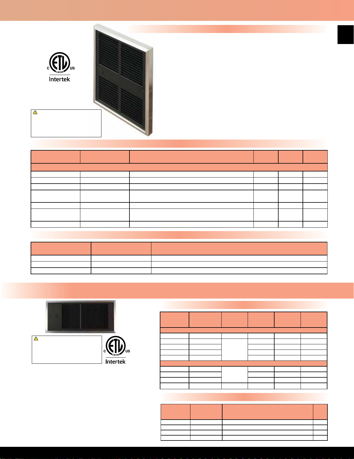
305 Series Midsized Commercial Fan Forced Wall Heater - Multiple Wattage
Features
• Wattage selectable at time of installation
• Models shipped wired to highest wattage
• Approved for horizontal mounting - right or left discharge
• Fan purge circuit
• Disconnect switch
• Drywall depth embossments on back can
• 18 gauge powder coated steel & extruded Aluminum front
• Manual reset thermal limit
• Steel block n element
• Propeller style fan blade: 1060 RPM motor; 100 CFM
• Weight = 6 lbs.
!
WARNING: This product can expose you
to chemicals including nickel which is known
to the State of California to cause cancer,
and chromium, which is known to the State
of California to cause birth defects and/or
reproductive harm. For more information go
to www.P65Warnings.ca.gov.
• Rough in dimensions: 9 1⁄4” Wide x 12 1⁄8” High x 3 5⁄8” Deep
• Grill dimensions: 10” Wide x 13 1⁄8” High
• Approved for wall or ceiling installation
• Models available with single pole thermostats
• Made in U.S.A.
Standard Models
39
MFG CATALOG
NUMBER
MFG MODEL
NUMBER
SELECTABLE INSTALLATION WATTAGE
MAX
BTUs
VOLTS
MAX
AMPS
TAMPERPROOF IN-BUILT DOUBLE POLE THERMOSTAT (40º - 100º TEMPERATURE RANGE)
09962102 E3055T2DWB 750 or 1500 5120 120 12.5
09962202 E3058T2DWB 900 or 1800 6143 120 15.0
09962502 F3052T2DWB 1000 or 2000 6826 208 8.3
09456902 F30522T2DWB
500 or 750 or 1000 or 1250
or 1500 or 1750 or 2250
7680 208 10.8
09962802 H3052T2DWB 750 or 1000 - 1500 or 2000 6826 208 / 240 8.3
09457202 H30522T2DWB
500 or 750 or 1000 or 1250
or 1500 or 1750 or 2250
7680 240 9.4
09963102 G3052T2DWB 2000 6826 277 7.2
Accessories
MFG CATALOG
NUMBER
09969402 305EX8 1” EXTENDER
09969302 305EX16 2” EXTENDER
09969202 305EX32 4” SURFACE MOUNT FRAME
MFG MODEL
NUMBER
DESCRIPTION
4400 Series Low Prole Commercial Fan Forced Wall Heater - With Wall Box
Standard Models
!
WARNING: This product can expose you
to chemicals including nickel which is known
to the State of California to cause cancer,
and chromium, which is known to the State
of California to cause birth defects and/or
reproductive harm. For more information go
to www.P65Warnings.ca.gov.
• Powder coated 20 gauge steel front with extruded
Aluminum frame
• Manual reset thermal limit.
• Finned tubular steel element
• Propeller style fan blade - 2200 RPM/70 CFM
• Weight 9 lbs.
• Rough in dimensions:
14 1⁄2” Wide x 7 1⁄8” High x 3 1⁄2” Deep
• Grill dimensions:16 7⁄8” Wide x 8” High
• Unit not approved for ceiling mount applications
• Unit can be positioned to allow left, right
or top discharge
• Made in U.S.A.
Note: Please see Draft Barrier Heaters - General Product Information
page for custom color availability; add 10% to net heater cost.
MFG
CATALOG
NUMBER
03283202 F4420T2RP 208 2000 6826 9.6
03283302 HF4475T2RP
03283402 HF4410T2RP 1000 / 750 3413 / 2560 4.2 / 3.6
03283502 HF4415T2RP 1500 / 1125 5120 / 3840 6.3 / 5.4
03283602 HF4420T2RP 2000 / 1500 6826 / 5120 8.3 / 7.2
03283702 E4475TRP
03283802 E4410TRP 1000 3413 8.33
03283902 E4415TRP 1500 5120 12.5
03284002 F4420TRP 208 2000 6826 9.6
MFG
CATALOG
NUMBER
03299102 4400EX8 1” SEMI RECESSING EXTENDER 2
03299002 4400EX16 2” SEMI RECESSING EXTENDER 3
03298902 4400EX32 4” SURFACE MOUNTING FRAME 4
03284402 4300PB WALL PLATE ADAPTOR (OD 21.5”x12.25”) 1
MFG
MODEL
NUMBER
DOUBLE POLE IN-BUILT THERMOSTAT (RANGE 0º - 110º F)
SINGLE POLE IN-BUILT THERMOSTAT (RANGE 0º - 110º F)
VOLTS WATTS
750 / 562 2560 / 1920 3.1 / 2.7
240/208
750 2560 6.25
120
MAX
BTUs
Accessories
MFG
MODEL
NUMBER
DESCRIPTION
AMPS
WT.
(LBS)
Page 41

AFA Series Commercial Fan Forced Wall Heater
40
deliver a quiet 175 CFM of down ow air. The heating element shall be of the sealed tubular type with large, parallel steel ns for
quick heat transfer. Unit shall have as a standard, a thermal overload cut-off for added safety, fan delay switch and built-in tamper
proof thermostat which shall be calibrated to provide a range of 0°F. to 110°F. and manual disconnect switch. Optional accessories
shall include a surface and semi-recess mounting adapter. All heaters shall be listed by ETL. The heating element shall be supplied
with a manufacturer's 1-year limited warranty.
MFG
CATALOG
NUMBER
IN-BUILT SINGLE POLE TAMPERPROOF THERMOSTAT (0° - 110° TEMPERATURE RANGE)
FOR DOUBLE POLE THERMOSTAT REPLACE “T” IN MODEL NUMBER WITH “T2” -- ADD $50
03820502 AFA107D 750 2560
03819902 AFA110D 1000 3413 8.3
03808802 AFA115D 1500 5120 12.5
03809302 AFA840D 4000 13800
03810202 AFA848D 4800 16560 23
03809402 AFA215D 1500 / 1125 5120 / 3840
03809502 AFA220D 2000 / 1500 6284 / 5120 8.3 / 7.2 27
03809602 AFA230D 3000 / 2250 10350 / 7763 12.5 /10.8
03810302 AFA248D 4800 16560 240 20
03809802 AFA715D 1500 5120
03809902 AFA720D 2000 6284 7.2 27
03810002 AFA730D 3000 10350 10.8
03810102 AFA740D 4000 13800 14.4
03810402 AFA748D 4800 16560 17.3
03980702 AFA840D-3* 4000 13800
03980802 AFA240D-3* 4800 16560 13.33
03980902 AFA848D-3* 4000 13800
03981002 AFA248D-3* 4800 16560 11.57
03964202 M3324TD-RPi 3360/1680 11468/5734
03964302 M3325TD-RPi 4032/2016 13761/6881 18.3/9.16
*Indicates 3-Phase model. All other models are 1-Phase.
MFG
CATALOG
NUMBER
03778502 BOX AFA Additional Rough-in Box
03784502 AFAEX33 4” Surface Mounting Frame 1
03829302 AFAEX16 2” semi recess extender 1
----- Sufx - HD 16 Gauge Steel Heavy Duty Grill Factory Installed 2
MFG
MODEL
NUMBER
Features
• Disconnect switch
• Automatic fan delay circuit
• Automatic reset thermal limit
• Powder coated 18 gauge steel grill
with extruded Aluminum front frame
• Steel block n element
• Vane axial fan blade: 600 RPM motor; 175 CFM
• Rough-in dimensions: 14
• Grill dimensions: 15
1
⁄8” Wide x 19 ½” High x 4” Deep
29
⁄32” Wide x 20 27⁄32” High
• Built-In tamper proof thermostat
• Made in U.S.A.
!
WARNING: This product can expose you
to chemicals including nickel which is known
to the State of California to cause cancer,
and chromium, which is known to the State
of California to cause birth defects and/or
reproductive harm. For more information go
to www.P65Warnings.ca.gov.
Product Specications
Furnish and install Heavy-Duty Forced Air wall heaters, where specied. The heaters
shall be constructed of a heavy 18 gauge steel housing with an extruded Aluminum
frame. The rough-in dimensions are 14
1
⁄8” Wide x 19 ½” High x 4” Deep. The units shall
be available in ratings from 750 to 4800 Watts at 240, 208, and 277 Volts. The heaters
shall have a low-speed 600 RPM, 4-pole motor which drives a vane axial blower to
Standard Models
WATTS BTUs VOLTS AMPS WT. (LBS)
6.25
120
26
2903809702 AFA240D 4000 / 3000 13800 / 10350 16.7/14.4
29
30
27
International Models
208
240 / 208
277
208
240
220
19.2
6.2 / 5.4
4.1 26
11. 11
9.64
15.3/7.64
Accessories
MFG
MODEL
NUMBER
DESCRIPTION TYPE WT. (LBS)
3
Field Installed
Page 42

AFC & AFH Series Heavy-Duty Fan Forced Wall Heaters
Features
• Powder coated bar stock steel tamper proof grille, with extruded Aluminum frame and
16 gauge housing
• In-Built double pole tamper proof thermostat with a 40°-120°F temperature range and
positive off; 3 phase heaters have 3 pole thermostat for positive off position with a
40°-120° temperature range
• Manual reset thermal limit switch
• Corrosion resistant steel tubular element with brazed steel ns
• Permanently lubricated, unit bearing, shaded pole motor with impedance protection
• Propeller type fan blade: • Made in U.S.A.
!
WARNING: This product can expose you
to chemicals including nickel which is known
to the State of California to cause cancer,
and chromium, which is known to the State
of California to cause birth defects and/or
reproductive harm. For more information go
to www.P65Warnings.ca.gov.
HEATER WALL BOX
MFG CATALOG
NUMBER
06911302 AFC8120T
06911902 AFC2120T 240 8.3
06911702 AFC7120T 277 7.2
03846202 AFC8380
03846402 AFC2320 240 4.8
06912302 AFC8130T
06913102 AFC2130T 240 12.5
06912702 AFC7130T 277 10.8
03238502 AFC8330
03846502 AFC2330 240 7.3
06913302 AFC8140T
06913802 AFC2140T 240 16.7
06913602 AFC7140T 277 14.4
06914002 AFC8340T 208
06914102 AFC2340T 240 9.6
06914302 AFC8150T
06915102 AFC2150T 240 20.8
06914802 AFC7150T 277 18.1
06915302 AFC8350T 208
06915602 AFC2350T 240 12.0
MFG CATALOG
NUMBER
06916102 AFH8120T
06916802 AFH2120T 240 8.3
03122902 AFH7120T 277 7.2
03846602 AFH8320
03846801 AFH2320 240 4.8
06876802 AFH8130T
06917702 AFH2130T 240 12.5
03122802 AFH7130T 277 10.8
03846702 AFH8330
03846901 AFH2330 240 7.3
06917802 AFH8140T
06918102 AFH2140T 240 16.7
03119902 AFH7140T 277 14.4
06918502 AFH8340T 208
03166502 AFH2340T 240 9.6
03129802 AFH8150T
03121302 AFH2150T 240 20.8
03123802 AFH7150T 277 18.1
06919002 AFH8350T 208
03130702 AFH2350T 240 12.0
MFG MODEL
NUMBER
HEATER WALL BOX
MFG MODEL
NUMBER
1400 RPM motor; 245 CFM • Wall box included with heater
• Factory installed options:
- contactors (3420 & 3450 series)
- circuit breakers (3450 series)
- control transformers (3450 series)
Standard Models
MFG CATALOG
NUMBER
SERIES AFC - ROUGH-IN DIMENSIONS: 19
691574 Box 3420
MFG CATALOG
NUMBER
SERIES AFH - ROUGH-IN DIMENSIONS: 23
691918 Box 3450
MFG MODEL
NUMBER
GRILL DIMENSIONS: 21 1⁄2” H x 17 1⁄2” W
MFG MODEL
NUMBER
GRILL DIMENSIONS: 25” H x 17 1⁄2” W
WATTS BTUs VOLTS PH AMPS
5
⁄8” H x 14 7⁄16” W x 4 1⁄8” D
208
2000 6826
2000 6826
3000 10239
3000 10239
4000 13652
5000 17065
WATTS BTUs VOLTS PH AMPS
5
⁄16” H x 14 7⁄16” W x 4 1⁄8” D
2000 6826
2000 6826
3000 10239
3000 10239
4000 13652
5000 17065
208
208
208
208
208
208
208
208
208
208
208
1
3
1
3
1
3
1
3
1
3
1
3
1
3
1
3
9.6
5.6
14.4
8.3
19.2
11.1
24
13.9
9.6
5.6
14.4
8.3
19.2
11.1
24.03
13.9
41
WT.
(LBS)
41
WT.
(LBS)
55
Page 43

42
AFC & AFH Series Heavy-Duty Fan Forced Wall Heaters
Product Specications
Contractor shall supply and install heavy duty wall mounted forced air electric heaters of the wattage, voltage and
phase as specied. The heater shall so be designed to provide an even distribution of heated air to the space to be
heated by drawing return air in the peripheral area of the heater across and through the element which shall then be
discharged from the center section of the heater by means of an electric motor and axial ow fan blade. Heaters shall
be recessed type to extend no more than 1
from the nished wall or semi-recessed type to extend no more than 3 1⁄2” from nished wall or semi-recessed type to
extend no more than 2 1⁄2” from nished wall.
ENCLOSURE:
Heater front shall withstand 10.8 ft. lbs. (324 poundals) impact and 400 lbs. static force applied to an 8 sq. in. area at
center grille location with less than 1⁄16” permanent distortion. The combination return and supply grille assembly shall
be constructed of 1⁄16” x 3⁄8” rounded edge horizontal steel louvers which shall be spaced for maximum opening of 1⁄4”.
Louvers shall be welded at every intersection to three evenly spaced 1/16” diameter vertical members and completely
framed in a heavy gauge natural anodized Aluminum extrusion. Front assembly shall be attached to the chassis by
hidden tamper-resistant (Allen-head) machine screws. All other parts shall be 16 gauge steel Zinc coated, both sides
nished in a high gloss or bronze colored baked powder coat nish.
MOTOR:
Motor shall be a permanently lubricated unit bearing, totally enclosed shaded pole type with impedance protection.
Motors shall operate at no more than 1400 RPM and shall be same voltage as the heater. A protective shield shall
surround the motor to separate return air from heated air.
PERFORMANCE:
Heaters shall have a rating of 245 CFM at 660 F.P.M. with a maximum temperature rise of 73°F.
ELEMENTS:
Element assemblies shall consist of two or three corrosion resistant steel sheathed type elements mechanically
bonded to common corrosion resistant steel ns. Each sheathed element shall consist of helically coiled Nickel
Chromium alloy resistant wire completely embedded in and surrounded by Magnesium Oxide, enclosed and wedged
into corrosion resistant steel sheaths. Elements shall have 2” cold conductor pins extending into the sheath and shall
have a density of no more than 60 Watts per inch.
THERMAL OVERLOAD:
Heaters shall be equipped with a “manual reset” thermal overload which disconnects elements and motor in the event
normal operating temperatures are exceeded. For safety, if opened due to abnormal temperature, thermal overload
shall remain open until manually reset. Automatic reset thermal overloads which allow the element to continue to cycle
under abnormal conditions will not be accepted.
APPROVAL:
Heaters shall be ETL Listed.
OPTIONAL CONTROL SYSTEMS:
Heaters shall be operated from wall-mounted, line voltage, heavy-duty (tamper-proof) thermostats. Heaters with
built-in, pre-wired contactors shall be operated from wall-mounted, line voltage, pilot duty (tamper-proof) thermostats.
Heaters built with, pre-wired contactors (and control transformers) shall be operated from wall-mounted, pilot duty
(24V) or (120V) wall-mounted tamper-proof thermostats. Heaters shall be controlled by integrally mounted thermostats.
Thermostats shall be heavy-duty, hydraulic type with a temperature range of 40°F - 120°F for double pole units and
40°F - 120°F for three pole units and with remote sensing bulb placed in the return air. Thermostats shall be electrically
rated at least 125% of heater rating. Thermostats shall be electrically rated at least 125% of heater rating. Thermostats
shall also act as a disconnect by breaking all ungrounded conductors in the OFF position. (Thermostat control knob
shall be covered by a 16 gauge tamper-proof access plate to prevent adjustment by unauthorized personnel.)
CONTACTORS:
Where required, heaters shall be equipped with heavy-duty, denite purpose contactors with ame path separators
and dust covers. Contactors shall cycle all ungrounded conductors. Contactors shall have holding coils (of the same
voltage as the heater) or (120 Volts) or (24 Volts).
CONTROL TRANSFORMERS:
Heater shall be equipped with a Class 2 control transformer, sealed rating of 20 VA, to supply control circuits of (24
Volts) or (120 Volts). (120 Volt secondaries not available in single phase heaters over 3 KW).
CIRCUIT BREAKERS (3450 Series Only):
Heaters shall be equipped with built-in circuit breakers in order to allow the heaters to be supplied from feeder taps.
A separate switch providing a positive off for control circuits shall be included where required. Circuit breakers and
control switches shall be arranged so that all line side conductors will be separately enclosed when heater front is
removed for servicing so that no current carrying parts are accessible without the use of additional tools.
1
⁄2” from the nished wall or surface mounted to extend no more than 5 3⁄4”
Page 44
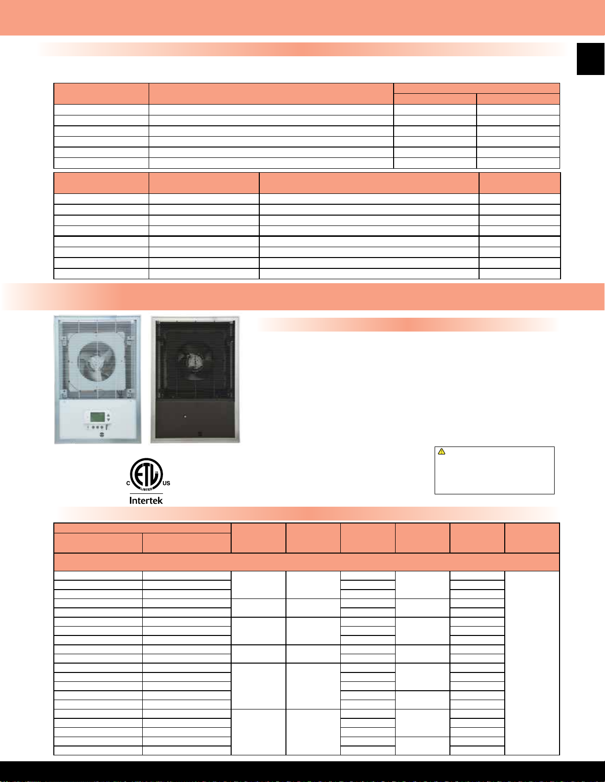
AFC & AFH Series Heavy-Duty Fan Forced Wall Heaters
Factory Installed Accessories
Units with transformers must have a contactor. A control transformer with 120V secondary is available on all 3-phase models,
208V/240V 1-phase units up to 3KW, and up to 4KW on 277V. All heaters must be installed with a wall box.
MFG MODEL
NUMBER
DESCRIPTION
Sufx - R Contactor with Coil same as heater YES YES
Sufx - R1 Contactor with 24V Coil YES YES
Sufx - R2 Contactor with 120V Coil YES YES
Sufx - C Circuit Breakers - all models NO YES
Sufx - A1 Control Transformers With 24V Secondary NO YES
Sufx - A2 Control Transformers With 120V Secondary NO YES
MFG CATALOG
NUMBER
MFG MODEL
NUMBER
DESCRIPTION
06916002 AFCEX34 4” Surface Mounting Sleeve 5
06915902 AFCEX16 2” Semi-Recessing Sleeve 4
06915802 AFCEX8 1” Semi-Recessing Sleeve 3
06915705 Box AFC Wall Box for AFC 4
03291202 AFHEX34 4” Surface Mounting Sleeve 6
03291302 AFHEX16 2” Semi-Recessing Sleeve 4
03291402 AFHEX8 1” Semi-Recessing Sleeve 3
06915702 Box AFH Wall Box for AFH 5
AFHSD Series Setback on Demand Heavy-Duty Fan Forced Wall Heaters
SERIES OPTIONS
AFC AFH
WT.
(LBS)
43
Features
AFHSD White
AFHSD Bankers Bronze
(Tamper Proof)
• Heavy duty architectural style
• Automatic fan purge circuit
• Manual reset thermal limit switch
• Powder coated bar stock grill with extruded
Aluminum frame and 16 gauge housing
• Set desired comfort level and set-back
level up to 12°F
• The thermostat learns your schedule
based on detected movement and returns
the area to the desired temperature using
two stage operation. If the thermostat does
not detect movement within one hour,
setback occurs to the preset level
• Occupancy sensor defaults to economy
mode after one hour, sensor has a 94
degree angular range and a 16’ linear range
• Tamper proof grill covers the thermostat
• Corrosion resistant steel tubular element
with brazed steel ns
• Permanently lubricated, unit bearing,
shaded pole motor with impedance
protection
• Factory preset to correct operating system
voltage of heater
• Propeller type fan blade:
-1400 RPM motor; 245 CFM
• Wall box included with heater
• Available in white, consult factory
• Made in USA
!
WARNING: This product can expose you
to chemicals including nickel which is known
to the State of California to cause cancer,
and chromium, which is known to the State
of California to cause birth defects and/or
reproductive harm. For more information go
to www.P65Warnings.ca.gov.
Features
HEATER
MFG CATALOG
NUMBER
03985102 AFH8120SD
03985202 AFH2120SD 240 8.3
03985302 AFH7120SD 277 7.2
03985402 AFH8320SD
03985502 AFH2320SD 240 4.8
03985602 AFH8130SD
03985702 AFH2130SD 240 12.5
03985802 AFH7130SD 277 10.8
03985902 AFH8330SD
03986002 AFH2330SD 240 7.3
03986102 AFH8140SD
03986202 AFH2140SD 240 16.7
03986302 AFH7140SD 277 14.4
03986402 AFH8340SD 208
03986502 AFH2340SD 240 9.6
03986602 AFH8150SD
03986702 AFH2150SD 240 20.8
03986802 AFH7150SD 277 18.1
03986902 AFH8350SD 208
03987002 AFH2350SD 240 12.0
MFG MODEL
NUMBER
SERIES AFHSD - ROUGH-IN DIMENSIONS: 23
WATTS BTUs VOLTS PH AMPS
1
⁄16” H x 14 1⁄4” W x 4 1⁄4” D
1
GRILL DIMENSIONS: 25
2000 6826
2000 6826
3000 10239
3000 10239
4000 13652
5000 17065
⁄32” H x 17 7⁄16” W
208
208
208
208
208
208
1
3
1
3
1
3
1
3
9.6
5.6
14.4
8.3
19.2
11.1
24.03
13.9
WT.
(LBS)
55
Page 45

44
3310 Series Fan Forced Wall Heater - Without Summer Fan Switch
Features
• Powder coated 18 gauge steel front
• Automatic reset thermal limit
• Vane axial fan blade: 600 RPM / 175 CFM
• Rough in dimensions:
1
14
⁄8
” Wide x 19 ½” High x 4” Deep
• Grill dimensions: 16 3⁄16” Wide x 21” High
• Steel block n element
• Weight 22 lbs.
• Units with dual wattage, factory wired to highest wattage
• Wattage selectable at time of installation on some models
• Made in U.S.A.
Standard Models
MODELS WITH IN-BUILT DOUBLE POLE THERMOSTAT (0º - 110º F TEMPERATURE RANGE)
IVORY WHITE
MFG CATALOG
NUMBER
03263402 E3312T2RP 03264802 E3312T2RPW 1000 3413
03263502 E3313T2RP 03264902 E3313T2RPW
03263602 F3316T2RP 03265002 F3316T2RPW 4000 13648
03263702 F3317T2RP 03265102 F3317T2RPW 4800 16380 23
03264002 HF3315T2RP 03265402 HF3315T2RPW
03264102 HF3316T2RP 03265502 HF3316T2RPW
03264202 H3317T2RP 03265602 H3317T2RPW 4800 16380 240 20.0
03264302 G3314T2RP 03265702 G3314T2RPW 2000 6826
03264402 G3315T2RP 03265802 G3315T2RPW 3000 10240 10.8
03264502 G3316T2RP 03265902 G3316T2RPW 4000 13648 14.4
03264602 G3317T2RP 03266002 G3317T2RPW 4800 16380 17.3
MFG MODEL
NUMBER
MFG CATALOG
NUMBER
MFG MODEL
NUMBER
WATTS
1500 5120 12.5
750 2560 6.25
3000 / 2250 10240
1500 / 1125 5120 6.2 / 5.4
4000 / 3000 13648 16.8 / 14.4
2000 / 1500 6826 8.3 / 7.2
MAX
BTUs
!
WARNING: This product can expose you
to chemicals including nickel which is known
to the State of California to cause cancer,
and chromium, which is known to the State
of California to cause birth defects and/or
reproductive harm. For more information go
to www.P65Warnings.ca.gov.
VOLTS AMPS
8.3
120
208
240 / 208
277
19.2
12.5 / 10.8
7.2
MODELS WITH IN-BUILT SINGLE POLE THERMOSTAT (0º - 110º F TEMPERATURE RANGE)
03825202 E3312TRP 03826102 E3312TRPW 1000 3413
03806502 E3313TRP 03841602 E3313TRPW
03799402 F3316TRP 03841802 F3316TRPW 4000 13648
03803002 F3317TRP 03841902 F3317TRPW 4800 16380 23
03805602 HF3315TRP 03822202 HF3315TRPW
03799802 HF3316TRP 03822302 HF3316TRPW
03803102 H3317TRP 03822402 H3317TRPW 4800 16380 240 20.0
03805902 G3314TRP 03842602 G3314TRPW 2000 6826
03807502 G3315TRP 03842702 G3315TRPW 3000 10240 10.8
03800102 G3316TRP 03842802 G3316TRPW 4000 13648 14.4
03791702 G3317TRP 03842902 G3317TRPW 4800 16380 17.3
MODELS WITHOUT AN IN-BUILT THERMOSTAT
03266202 E3312RP 03267602 E3312RPW 1000 3413
03266302 E3313RP 03267702 E3313RPW
03285302 F3316RP 03267802 F3316RPW 4000 13648
03266502 F3317RP 03267902 F3317RPW 4800 16380 23
03266802 HF3315RP 03268202 HF3315RPW
03266902 HF3316RP 03268302 HF3316RPW
03267002 H3317RP 03268402 H3317RPW 4800 16380 240 20.0
03267102 G3314RP 03268502 G3314RPW 2000 6826
03267202 G3315RP 03268602 G3315RPW 3000 10240 10.8
03267302 G3316RP 03268702 G3316RPW 4000 13648 14.4
03267402 G3317RP 03268802 G3317RPW 4800 16380 17.3
1500 5120 12.5
750 2560 6.25
3000 / 2250 10240
1500 / 1125 5120 6.2 / 5.4
4000 / 3000 13648 16.8 / 14.4
2000 / 1500 6826 8.3 / 7.2
1500 5120 12.5
750 2560 6.25
3000 / 2250 10240
1500 / 1125 5120 6.2 / 5.4
4000 / 3000 13648 16.8 / 14.4
2000 / 1500 6826 8.3 / 7.2
120
208
240 / 208
277
120
208
240 / 208
277
8.3
19.2
12.5 / 10.8
7.2
8.3
19.2
12.5 / 10.8
7.2
Page 46

3310 Series Fan Forced Wall Heater - With Summer Fan Switch
Features
• Powder coated 18 gauge steel front
• Automatic reset thermal limit
• Steel block n element
• Weight 22 lbs.
• Vane axial fan blade: 600 RPM / 175 CFM
• Grill dimensions: 16
•
Rough in dimensions: 14
• Units with dual wattage, factory wired to highest wattage
• Wattage selectable at time of installation on some models
• Made in U.S.A.
Typical Specications: Furnish and install Electric Forced Air Heaters where specied. The heaters shall be constructed of a heavy
gauge steel housing. The rough-in dimensions are 14
ivory or white color. The units shall be available in ratings from 750 through 4800 Watts. The heaters shall have a low speed 600
RPM motor which drives a vane axial blower to deliver a quiet 175 CFM of down ow air. The heating element shall be of the sealed
block n type with large, parallel steel ns for quick heat transfer. Unit shall have a standard thermal overload cutoff for added safety,
a fan switch for fan only operation, and is available with a single pole, or double pole built-in thermostat, or no thermostat. The in-
built thermostat shall be calibrated to provide a range of 0℉ - 110℉. All heaters shall be listed by ETL. The heating element shall
be supplied with a manufacturer’s 1 year limited warranty.
MODELS WITH IN-BUILT DOUBLE POLE THERMOSTAT (0º - 110ºF TEMPERATURE RANGE)
IVORY WHITE
MFG CATALOG
NUMBER
03260602 E3312T2SRP 03262002 E3312T2SRPW 1000 3413
03260702 E3313T2SRP 03262102 E3313T2SRPW
03260802 F3316T2SRP 03262202 F3316T2SRPW 4000 13648
03260902 F3317T2SRP 03262302 F3317T2SRPW 4800 16380 23
03261202 HF3315T2SRP 03262602 HF3315T2SRPW
03261302 HF3316T2SRP 03262702 HF3316T2SRPW
03261402 H3317T2SRP 03262802 H3317T2SRPW 4800 16380 240 20.0
MFG MODEL
NUMBER
MFG CATALOG
NUMBER
3
⁄16” Wide x 21” High
1⁄8” Wide x
19 ½”
High x
4”
Deep
!
WARNING: This product can expose you
to chemicals including nickel which is known
to the State of California to cause cancer,
and chromium, which is known to the State
of California to cause birth defects and/or
reproductive harm. For more information go
to www.P65Warnings.ca.gov.
Product Specications
1
⁄8” Wide x 19 ½” High x 4” Deep. The nish shall be powder coated paint in
Standard Models
MFG MODEL
NUMBER
WATTS
1500 5120 12.5
750 2560 6.25
3000 / 2250 10240
1500 / 1125 5120 6.2 / 5.4
4000 / 3000 13648 16.8 / 14.4
2000 / 1500 6826 8.3 / 7.2
MAX
BTUs
VOLTS AMPS
8.3
120
208
240 / 208
19.2
12.5 / 10.8
45
MODELS WITH IN-BUILT SINGLE POLE THERMOSTAT (0º - 110ºF TEMPERATURE RANGE)
03825702 E3312TSRP 03825902 E3312TSRPW 1000 3413
03796102 E3313TSRP 03840102 E3313TSRPW
03777102 F3316TSRP 03840202 F3316TSRPW 4000 13648
03777802 F3317TSRP 03840302 F3317TSRPW 4800 16380 23
03776002 HF3315TSRP 03840702 HF3315TSRPW
03776902 HF3316TSRP 03840802 HF3316TSRPW
03777602 H3317TSRP 03840902 H3317TSRPW 4800 16380 240 20.0
International Models
---- ---- 03964802 M3315T2SRPWi
---- ---- 03964902 M3316T2SRPWi
Note: Fan switch not available on 277V models. 277V models are available without a fan switch on previous page.
1500 5120 12.5
750 2560 6.25
3000 / 2250 10240
1500 / 1125 5120 6.2 / 5.4
4000 / 3000 13648 16.8 / 14.4
2000 / 1500 6826 8.3 / 7.2
3360 11468
1680 5734 7.64
4032 13761 18.33
2016 6881 9.16
120
208
240 / 208
220
Accessories - All Models
IVORY WHITE
MFG CATALOG
NUMBER
03778502 BOX3310 03778502 BOX3310 ADDITIONAL BACK CAN
03299502 3310EX33R 03299602 3310EX33WR SURFACE MOUNTING FRAME
MFG MODEL
NUMBER
SUFFIX D DISCONNECT SWITCH Factory Installed
MFG CATALOG
NUMBER
MFG MODEL
NUMBER
DESCRIPTION ACCESSORY TYPE
Field Installed
8.3
19.2
12.5 / 10.8
15.27
Page 47

46
3200 Series Midsized Fan Forced Wall Heater - With Wall Box
Features
• Units have white powder coat nish
• Approved for horizontal mounting - right or left discharge
Shown with Built-In Thermostat
• Drywall depth embossments on back can
• Powder coated 18 gauge steel front
• Manual reset thermal limit
• Finned tubular steel element
• Weight 6 lbs.
• Propeller style fan blade: 2200 RPM / 70 CFM
• Optional eld installed In-Built thermostat
1
• Rough in dimensions: 9
⁄4” Wide, 12 1⁄8” High, 3 5⁄8” Deep
• Grill dimensions: 9 25⁄32” Wide, 13” High
• Made in U.S.A.
“TWO WIRE INSTALLATION”
Standard Models
!
WARNING: This product can expose you
to chemicals including nickel which is known
to the State of California to cause cancer,
and chromium, which is known to the State
of California to cause birth defects and/or
reproductive harm. For more information go
to www.P65Warnings.ca.gov.
MFG CATALOG
NUMBER
03834602 F3220T2RPW 208 2000 6826 9.6
03834702 H3275T2RPW 240 750 2560 3.1
03834802 HF3210T2RPW
03834902 HF3215T2RPW 1500 / 1125 5120 / 3840 6.3 / 5.4
03835002 HF3220T2RPW 2000 / 1500 6826 / 5120 8.3 / 7.2
03835102 HF3222T2RPW 2250 / 1688 7680 / 5762 9.4 / 8.1
International Models - BUILT-IN DOUBLE POLE (POSITIVE OFF) THERMOSTAT 40° - 100°F RANGE
03963802 M3210T2RPWi
03963902 M3215T2RPWi 1260 4300 5.7
03964002 M3220T2RPWi 1680 5734 7.6
03964102 M3222T2RPWi 1890 6451 8.6
Standard Models - BUILT-IN SINGLE POLE (POSITIVE OFF) THERMOSTAT 40° - 100°F RANGE
03835202 E3275TRPW
03835302 E3210TRPW 1000 3413 8.33
03835402 E3215TRPW 1500 5120 12.5
03835502 E3275RPW
03835602 E3210RPW 1000 3413 8.33
03835702 E3215RPW 1500 5120 12.5
03835802 F3220RPW 208 2000 6826 9.6
03835902 H3275RPW 240 750 2560 3.1
03836002 HF3210RPW
03836102 HF3215RPW 1500 / 1125 5120 / 3840 6.3 / 5.4
03836202 HF3220RPW 2000 / 1500 6826 / 5120 8.3 / 7.2
03836302 HF3222RPW 2250 / 1688 7680 / 5762 9.4 / 8.1
MFG MODEL
NUMBER
BUILT-IN DOUBLE POLE (POSITIVE OFF) THERMOSTAT 40° - 100°F RANGE
VOLTS WATTS
1000 / 750 3413 / 2560 4.2 / 3.6
240/208
840 2867 3.8
220
750 2560 6.25
120
NO BUILT-IN THERMOSTAT
750 2560 6.25
120
1000 / 750 3413 / 2560 4.2 / 3.6
240/208
MAX
BTUs
AMPS
FIELD INSTALLED COMPONENTS
MFG
CATALOG
NUMBER
03836402 32T1
03836502 32T2
MFG
MODEL
NUMBER
Accessories
DESCRIPTION
Single Pole thermostat with positive off
for 120V units 40
Double Pole thermostat with positive off
for 240/208V units 40
o
- 100o F
o
- 100o F
SURFACE MOUNTED EXTENDERS & FRAMES
WHITE
MFG
CATALOG
NUMBER
09969702 303EX8RW 1” EXTENDER
09969602 303EX16RW 2” EXTENDER
09969502 303EX32RW 4” SURFACE MOUNT FRAME
MFG
MODEL
NUMBER
DESCRIPTION
Page 48
4300 Series Low Prole Fan Forced Wall Heater - With Wall Box
Features
With Built-In Thermostat
• Available in ivory or white
• Powder coated 20 gauge steel front
• Manual reset thermal limit
• Finned tubular steel element
• Weight 9 lbs.
!
WARNING: This product can expose you
to chemicals including nickel which is known
to the State of California to cause cancer,
and chromium, which is known to the State
of California to cause birth defects and/or
reproductive harm. For more information go
to www.P65Warnings.ca.gov.
• Propeller style fan blade - 2200 RPM / 70 CFM
• Rough in dimensions:
14 1⁄2” Wide, 7 1⁄8” High,3 1⁄2” Deep
• Grill dimensions: 16 3⁄4” Wide, 7 5⁄8” High
• Unit not approved for ceiling mount applications
• Unit can be positioned to allow left, right or top discharge
Without Built-In Thermostat
• Made in U.S.A.
Standard Models
IVORY WHITE
MFG CATALOG
NUMBER
03276902 F4320T2RP 03277402 F4320T2RPW 208 2000 6826 9.6
03277002 HF4375T2RP 03277502 HF4375T2RPW
03277102 HF4310T2RP 03277602 HF4310T2RPW 1000 / 750 3413 / 2560 4.2 / 3.6
03277202 HF4315T2RP 03277702 HF4315T2RPW 1500 / 1125 5120 / 3840 6.3 / 5.4
03277302 HF4320T2RP 03277802 HF4320T2RPW 2000 / 1500 6826 / 5120 8.3 / 7.2
---- ---- 03964402 M4375T2RPi
---- ---- 03964502 M4310T2RPi 840 2869 3.8
---- ---- 03964602 M4315T2RPi 1260 4300 5.7
---- ---- 03964702 M4320T2RPi 1680 5733 7.6
03277902 E4375TRP 03278702 E4375TRPW
03278002 E4310TRP 03278802 E4310TRPW 1000 3413 8.33
03278102 E4315TRP 03278902 E4315TRPW 1500 5120 12.5
03278202 F4320TRP 03279002 F4320TRPW 208 2000 6826 9.6
03278302 HF4375TRP 03279102 HF4375TRPW
03278402 HF4310TRP 03279202 HF4310TRPW 1000 / 750 3413 / 2560 4.2 / 3.6
03278502 HF4315TRP 03279302 HF4315TRPW 1500 / 1125 5120 / 3840 6.3 / 5.4
03278602 HF4320TRP 03279402 HF4320TRPW 2000 / 1500 6826 / 5120 8.3 / 7.2
03279502 E4375RP 03280302 E4375RPW
03279602 E4310RP 03280402 E4310RPW 1000 3413 8.33
03279702 E4315RP 03280502 E4315RPW 1500 5120 12.5
03279802 F4320RP 03280602 F4320RPW 208 2000 6826 9.6
03279902 HF4375RP 03280702 HF4375RPW
03280002 HF4310RP 03280802 HF4310RPW 1000 / 750 3413 / 2560 4.2 / 3.6
03280102 HF4315RP 03280902 HF4315RPW 1500 / 1125 5120 / 3840 6.3 / 5.4
03280202 HF4320RP 03281002 HF4320RPW 2000 / 1500 6826 / 5120 8.3 / 7.2
MFG MODEL
NUMBER
International Models - DOUBLE POLE IN-BUILT THERMOSTAT (RANGE 0° - 110°F)
Standard Models - SINGLE POLE INBUILT THERMOSTAT (RANGE 0° - 110°F)
MFG CATALOG
NUMBER
DOUBLE POLE IN-BUILT THERMOSTAT (RANGE 0° - 110°F)
MFG MODEL
NUMBER
NO IN-BUILT THERMOSTAT
VOLTS WATTS
750 / 562 2560 / 1920 3.1 / 2.7
240/208
630 2150 2.9
220
750 2560 6.25
120
750 / 562 2560 / 1920 3.1 / 2.7
240/208
750 2560 6.25
120
750 / 562 2560 / 1920 3.1 / 2.7
240/208
MAX
BTUs
47
AMPS
Accessories
IVORY WHITE
MFG CATALOG
NUMBER
03276502 4300EX8 03284502 4300EX8W 1” SEMI RECESSING EXTENDER 2
03276602 4300EX16 03284602 4300EX16W 2” SEMI RECESSING EXTENDER 3
03276702 4300EX32 03284702 4300EX32W 4” SURFACE MOUNTING FRAME 4
03276802 4300P 03284802 4300PW WALL PLATE ADAPTOR (OD 21.5” x 12.25”) 1
FIELD INSTALLED THERMOSTATS
MFG MODEL
NUMBER
MFG CATALOG
NUMBER
03297702 43T SINGLE POLE THERMOSTAT 0
03297802 43T2 DOUBLE POLE THERMOSTAT 0
MFG MODEL
NUMBER
ACCESSORY OPTIONS
O
- 110O F 1
O
- 110O F 1
WT.
(LBS)
Page 49

4800 Series Register Style Fan Forced Wall Heater - With Wall Box
48
Features
• Units have white powder coat nish
• Powder coated 20 gauge steel front
• Manual reset thermal limit
• Finned tubular steel element
• Propeller style fan blade - 2200 RPM / 70 CFM.
1
!
WARNING: This product can expose you
to chemicals including nickel which is known
to the State of California to cause cancer,
and chromium, which is known to the State
of California to cause birth defects and/or
reproductive harm. For more information go
to www.P65Warnings.ca.gov.
• Rough in dimensions: 14
• Grill dimensions: 16 3⁄4” Wide x 7 5⁄8” High
• Unit not approved for ceiling mount applications
• Left discharge only. / Weight: 9lbs
• Made in U.S.A.
⁄2” Wide x 7 1⁄8” High x 3 1⁄2” Deep
Standard Models
MFG CATALOG
NUMBER
03281502 F4820T2RPW 208 2000 6826 9.6
03281602 HF4875T2RPW
03281702 HF4810T2RPW 1000 / 750 3413 / 2560 4.2 / 3.6
03281802 HF4815T2RPW 1500 / 1125 5120 / 3840 6.3 / 5.4
03281902 HF4820T2RPW 2000 / 1500 6826 / 5120 8.3 / 7.2
MFG MODEL
NUMBER
DOUBLE POLE IN-BUILT THERMOSTAT (40º - 130ºF TEMPERATURE RANGE)
VOLTS WATTS
750 / 562 2560 / 1920 3.1 / 2.7
240/208
MAX
BTUs
AMPS
SINGLE POLE IN-BUILT THERMOSTAT (0º - 110ºF TEMPERATURE RANGE)
03282002 E4875TRPW
03282102 E4810TRPW 1000 3413 8.33
03282202 E4815TRPW 1500 5120 12.5
03282302 F4820TRPW 208 2000 6826 9.6
03282402 E4875RPW
03282502 E4810RPW 1000 3413 8.33
03282602 E4815RPW 1500 5120 12.5
03282702 F4820RPW 208 2000 6826 9.6
03282802 HF4875RPW
03282902 HF4810RPW 1000 / 750 3413 / 2560 4.2 / 3.6
03283002 HF4815RPW 1500 / 1125 5120 / 3840 6.3 / 5.4
03283102 HF4820RPW 2000 / 1500 6826 / 5120 8.3 / 7.2
120
NO IN-BUILT THERMOSTAT
120
240/208
750 2560 6.25
750 2560 6.25
750 / 562 2560 / 1920 3.1 / 2.7
Accessories
MFG CATALOG
NUMBER
MFG MODEL
NUMBER
DESCRIPTION
WT.
(LBS)
03284502 4300EX8W 1” SEMI RECESSING EXTENDER 2
03284602 4300EX16W 2” SEMI RECESSING EXTENDER 3
03284702 4300EX32W 4” SURFACE MOUNTING FRAME 4
03284802 4300PW WALL PLATE ADAPTOR (OD 21.5” x 12.25”) 1
03297702 43T SINGLE POLE THERMOSTAT 0
03297902 48T2 DOUBLE POLE THERMOSTAT 40
O
- 110O F 1
O
- 130O F 1
Page 50

Draft Barrier Heaters - General Product Information
All Draft Barrier Heaters, unless otherwise noted, are build to order items. Consult factory for lead times.
Additional charges may be incurred if changes are made after production has begun - consult factory.
Electric Draft Barrier Features
• “UNI-LOCK” construction allows snap-t, 2 piece installation
• Heavy Gauge Aluminum Extruded enclosures, 6063 heat
treated to T-5 hardness
• DBT/DBF & RDBT-PD-12 gauge front & back
• ASHDB Series is 16 gauge Steel Front with 18 Steel gauge back
1
•
⁄4” pencil proof discharge louvers
How To Designate A Model
DIGIT EXAMPLE MFG MODEL NUMBER DESIGNATION - “ASI” DRAFT BARRIER
DIGIT 1= DBT Series Model Number (DBT/DBF, etc.)
Use if Pedestals are Required*
DIGIT 2= PD
DIGIT 3= 4
DIGIT 4= 250
DIGIT 5= ITS (etc)
COMPLETED EXAMPLE: DBT-PD-4250-ITS
NOTE: SEE 9100 AND 9300 SERIES PAGES FOR THEIR MODEL CONFIGURATION.
(for extended enclosure, specify amount of required enclosure on
order write up, IE: 4’ Heated length with 2’6” of extended enclosure
Wattage per Linera foot (may not exceed allowable wattages on
specic models, refer to catalog page to verify maximum WPF)
Control Options: Refer to List Price chart for available options
(Verify on each model which options may be factory installed)
2’ to 5’ Heaters require 2 pedestals
6’ to 8’ Heaters require 3 pedestals
9’ & 10’ Heaters require 4 pedestals
Heated Length of Heater
Voltage & Wattage Specication
• Thermal protection by full length linear limits
• Multiple heaters, factory wired on same back plate,
available in up to 10’ lengths
• Totally enclosed junction boxes
• Custom colors and nishes available (See Chart)
• Enclosures available for hydronic heating coils
(consult factory for more information)
49
NOTE:
• Extended enclosures and
Blank Sections are NOT
punched. When a Control
Section is specied, ALWAYS
allow for an extended enclosure
to compensate for the 6” or 12”
length of the Section required.
• Note on order when nished
backs are required and add list
adder to model list.
• Total heater amperage must
not exceed the 25-Amp rating
of the high temperature limit
at any voltage or wattage.
This applies to all Sill Line
Model Series.
VOLTAGE STANDARD WATTAGES PER FOOT HEATER LENGTHS
120-277 100, 125, 150, 165, 187, 200, 250*, 300, 333*, 375* 2’ through 10’
*Units with Extended Enclosures may require more Pedestals than standard length, must verify length of heater after extended enclosures for
total amount of pedestals. NOTE: All bottom inlet units must be mounted a minimum of 3 inches above nished oor.
All dual element ASHDB models have single phase elements.
Control Options
SUFFIX DESIGNATION DESCRIPTION
CS 6 6” control section / will contain up to 2 control options
CS 12 12” control section / will contain up to 3 control options
ITS Single Pole, 25 Amp integral thermostat, 120,208,240 & 277 Volts
ITD Double Pole, 25 Amp integral thermostat, 120,208,240 & 277 Volts
IDS Double Pole Disconnect, 20 Amp, 120, 208, 240 & 277 Volts
IDS 30 30 Amp disconnect (9300 Series)
IDS 40 40 Amp disconnect (9300 Series)
LVTR Low voltage controls (trans & relay) (9300 Series)
PR 120-277/24
PR 120-277/120
PR 120-277/240
ATR*
*Not suitable for International use
Note: Please refer to each model to verify how many controls may be
integrally mounted, Control sections will add length to the heater. Must
use control section with PR 240/24, PR 208/24, 208/208 and ATR
Note: If using line voltage thermostat on single phase heaters you
cannot exceed 25 Amps due to Amp rating of thermostat. 347, 480, and
600V models can use up to 30 Amps with in-built thermostat.
Power Relay, 18 Amp tested, Must specify coil voltage
Single Pole, rated 25 Amps, 120 to 240 Volts,
Contacts rated up to 277 Volts (must specify)
Coils are 24 Volt; 24 Volt transformer
Single Pole
WARNING: This product can expose you
to chemicals including nickel which is known
to the State of California to cause cancer,
and chromium, which is known to the State
of California to cause birth defects and/or
reproductive harm. For more information go
to www.P65Warnings.ca.gov.
!
CUSTOM PAINT COLORS
Durable Powder Coat Paint Finish
Bankers Bronze - standard color
Eggshell White
Black
Gray
Beige
Bronze Anodized*
*simulated powder
coat nish
Special Colors (5 lb. Increment)
ANODIZING*
* 204R1 Clear; 313R1
Bronze and Black
Page 51

9100 Series - Radius Front Draft Barrier Heater
50
ETL listed up to 250 Watts / foot
for industrial, commercial, or
residential applications
!
WARNING: This product can expose you
to chemicals including nickel which is known
to the State of California to cause cancer,
and chromium, which is known to the State
of California to cause birth defects and/or
reproductive harm. For more information go
to www.P65Warnings.ca.gov.
HOW TO DESIGNATE A MODEL:
Element Volts
E = 120
F = 208
G = 277
H = 240
• Standard color: Bankers Bronze
• “UNI-LOCK” construction allows snap-t, 2 piece installation
• Units can be controlled by optional In-Built thermostat
or can be constructed with relays and / or transformers
for low voltage or line voltage wall thermostats
• Thermal protection by full length manual reset linear limits
• Optional duplex receptacle section
• Wiring junction boxes on each end of the unit
• Custom colors and nishes available (consult factory)
• Limited by max Amp draw of 25 Amps (with no controls)
• Additional charges may be incurred if changes are made
after production has begun - consult factory
• Made in U.S.A.
E 91 96 250 ITS PD
Model Series
91
Heater Length
(inches)
28, 36, 48, 60,
72, 84, 96, 108,
or 120
Watts Per Foot
100, 125, 150,
165, 187, 200,
or 250
Features
Control Options
Refer to Draft
Barrier Heaters
pages
Factory Installed
Accessories
PD = Pedestal
DR = Receptacle
WM = Screen
Note: For control option pricing see page 49
Product Description
TECHNICAL INFORMATION
Air Intake Bottom
Air Discharge To p
Min Mounting Height 3”
Max Watts / Foot 250
Max Allowable Amps 25 Amps (16 Amps with disconnect)
Voltage / Phase 120V/208V/240V/277V Single Phase
Standard Models
MFG
MODEL
9128 28”
9136 36”
9148 48”
9160 60”
9172 72”
Heater
9184 84”
9196 96”
91108 108”
91120 120”
UNIT LENGTH
MFG
MODEL
91BS012 12”
91BS024 24”
91BS036 36”
91BS048 48”
91BS060 60”
91BS072 72”
Blank Section
91BS084 84”
91BS096 96”
91BS108 108”
91BS120 120”
Optional Controls That
Can Be Built Into Unit
UNIT LENGTH
TECHNICAL INFORMATION
1
Height 4
Depth 3
Length 28” to 120” in 1’ increments
Cabinet Material
Material Gauge
Thermostat and Disconnect Switch
(Control Section Required for Relays)
⁄2”
1
⁄8”
Aluminum
14
Factory Installed Accessories
SUFFIX DESCRIPTION
DR
PD
WM
Duplex Receptacle in 4” Extended
Enclosure (not available with 120” heater)
28” through 60” - 2 Required
72” through 96” - 3 Required
108” through 120” - 4 Required
1
⁄4” wire mesh under grill
Field Installed Accessories
MFG
MODEL
9100IC Inside Corner Section 90° or 135°
9100OC Outside Corner Section 90° or 135°
9100EC Right or Left End Cap
9100SP Splice Plate
DESCRIPTION
Note: All models are suitable for International use
Page 52

9100 Series - Radius Front Draft Barrier Heater
Product Specications
CABINET
9100 Series shall be constructed of 14 gauge extruded 6063 Aluminum heat treated to T5 hardness. The
uni-lock construction shall allow easy installation and access to back plate for wiring. The snap-t front
1
cover makes installation and service very simple. Custom factory enclosures to
built for exact wall to wall t up to 10 foot enclosure lengths. The 14 gauge back plate will have electrical
knockouts for incoming power on each end adjacent to junction box. Pedestal mounted units will have
incoming power connection through the pedestal on bottom of unit and will have smooth back for optional
nished back. The die punched front cover will have no screw heads or fasteners.
ELEMENTS
High mass sheathed element construction with Nickel-Chromium resistance wire embedded in compacted
efcient die-electric to ensure proper heat transfer. Aluminum ns mechanically bonded to stainless steel
tube allows for increased surface area and even heat transfer.
LIMIT CONTROLS
Manual reset hydraulic thermal overload covers full length of heating element and shuts down heater when
safe operating temperatures are exceeded.
⁄16 inch increments are
51
WIRING
Wiring shall be in either end of the enclosure. Wiring can be in the junction box or optional control section
1
if additional controls are needed. Pedestal mounted units shall have 1
⁄4” hole through the pedestal and in
the bottom of the enclosure for incoming power wiring. All heaters have a factory supplied built in raceway
for wiring from either end of the heater or for wiring of continuous heater connections.
CONTROLS
Optional controls include single or double pole thermostat and disconnect switch that are factory wired in
enclosed junction box on each end of heater enclosure. Relay, transformer relay and duplex receptacle
options shall be mounted in extended length control section. Control section will add to heater enclosure
length. The control section for the duplex receptacle will add 4” to enclosure length. The control section for
other optional components or combinations of components will have two options (6” or 12”) depending on
controls required.
APPLICATION
The 9100 series is ETL listed for commercial, industrial or residential applications on all units up to 250
Watts per foot.
Product Dimensions
OUTSIDE CORNER
SECTION
BACK VIEW
INSIDE CORNER
SECTION
6.0”
1-1/8"
1-9/16"
1-1/2"
4-1/2"
3" MINIMUM
3-1/8"
1-9/16"
FINISHED FLOOR
WALL MOUNT
3-1/8"
15/16"
PEDESTAL MOUNT
Ø .395 (TYP)
1-9/16"
2-1/16"
3"
2-7/16"
TYP
PEDESTAL
BASE
3-1/16”
6.0”
Page 53

52
HOW TO DESIGNATE A MODEL:
industrial or commercial applications.
!
WARNING: This product can expose you
to chemicals including nickel which is known
to the State of California to cause cancer,
and chromium, which is known to the State
of California to cause birth defects and/or
reproductive harm. For more information go
to www.P65Warnings.ca.gov.
9300 Series - Radius Front Draft Barrier Heater
Features
ETL listed up to 750 Watts/foot for
Not suitable for
residential applications.
F 93 96 B 561 3 ITS PD
• LEED and green compliance, 1 and 3 phase applications
• Industrial or commercial applications
• Standard color: Bankers Bronze (powder coated)
• Also available in other standard TPI colors and custom colors
for an additional charge
• Uni-lock construction for snap t 2 piece installation
• Temperature control can be in-built or wall mounted
• Thermal protection by full length manual reset linear limits
• Optional accessories include: duplex receptacle, and inside or
outside corner sections for wall to wall custom t.
• Additional charges may be incurred if changes are made after
production has begun - consult factory.
• Made in U.S.A.
Element Volts
F = 208
H = 240
G = 277
L = 347
P1 = 480
U1 = 600
J = 208
K = 240
P3 = 480
U3 = 600
Model Series
93
Single Phase
Three Phase
Heater Length
(inches)
28, 36, 48, 60,
72, 84, 96, 108,
or 120
Note: 480V single phase units minimum 36” heated length; 600V single phase units minimum 48” heated length
347-480-600 single phase and all three phase units are built with low voltage option factory installed
Note: For control option pricing see page 49.
TECHNICAL INFORMATION
Air Intake Bottom / Front
Air Discharge Top
Min Mounting Height 3” for bottom intake / 0” for front intake
Max Watts / Foot 750
Max Allowable Amps 25 without relay, 40 with relay
Voltage / Phase
208V/240V/277V/347V,480V,600V Single Phase
208V,240V,480V,600V Three Phase
Standard Models
MFG
MODEL
9328 28”
9336 36”
9348 48”
9360 60”
9372 72”
Heater
9384 84”
9396 96”
93108 108”
93120 120”
Note: All models are suitable for International use
UNIT LENGTH
MODEL
Blank Section
Inlet
B = Bottom
F = Front
Product Description
MFG
93BS012 12”
93BS024 24”
93BS036 36”
93BS048 48”
93BS060 60”
93BS072 72”
93BS084 84”
93BS096 96”
93BS108 108”
93BS120 120”
Watts Per Foot
1 Element
100, 125, 150,
165, 187, 200,
or 250
2 Elements
200, 250, 300,
330, 374, 500,
or 500
3 Elements
300, 375, 450,
495, 561, 600,
or 750
Cabinet Material
Material Gauge
Optional Controls That
Can Be Built Into Unit
UNIT LENGTH
# of Elements
1, 2, or 3
Control Options
Refer to Draft
Barrier Heaters
pages
Factory Installed
Accessories
PD = Pedestal
DR = Receptacle
WM = Screen
TECHNICAL INFORMATION
Height 7.5”
Depth 6.15”
Length 28” to 120” in 1’ increments
Aluminum
12
Thermostat, Disconnect Switch, Transformer
(Some congurations may require control section)
Factory Installed Accessories
SUFFIX DESCRIPTION
Duplex Receptacle in 4” Extended Enclosure
DR
(not available with 120” heater)
28” through 60” - 2 Required
PD
72” through 96” - 3 Required
108” through 120” - 4 Required
WM
1
⁄4” wire mesh under grill
IDS30 30 Amp/240V Disconnect Switch
IDS40 40 Amp/600V Disconnect Switch
Note: If using line voltage thermostat on 1 phase heaters, you
cannot exceed 25 Amps due to Amp rating of thermostat. 347,
480, and 600V can use 30 Amps with in-built thermostat.
Field Installed Accessories
MFG
MODEL
9300IC Inside Corner Section 90° or 135°
9300OC Outside Corner Section 90° or 135°
9300EC Right or Left End Cap
9300SP Splice Plate
DESCRIPTION
Page 54

Ø .395 (TYP)
3
1
16
"
TYP
PEDESTAL
BASE
3"
2
15
16
2
7
16
"
"
Ø .395 (TYP)
3
1
16
"
TYP
PEDESTAL
BASE
3"
7.500
6.15
2
15
16
7.500
6.15
3" MINIMUM
FINISHED FLOOR
2
7
16
"
"
12.0
9300 Series - Radius Front Draft Barrier Heater
Product Specications
CABINET
9300 Series shall be constructed of 12 gauge extruded 6063 Aluminum heat treated to T5 hardness. The
uni-lock construction shall allow easy installation and access to back plate for wiring. The snap-t front
cover makes installation and service very simple. Custom factory enclosures to
built for exact wall to wall t up to 10 foot enclosure lengths. The 12 gauge back plate will have electrical
knockouts for incoming power on each end adjacent to junction box. Pedestal mounted units will have
incoming power connection through the pedestal on bottom of unit and will have smooth back for optional
nished back. The die punched front cover will have no screw heads or fasteners.
ELEMENTS
High mass sheathed element construction with Nickel-Chromium resistance wire embedded in
compacted efcient die-electric to ensure proper heat transfer. Aluminum ns mechanically bonded to
stainless steel tube allows for increased surface area and even heat transfer.
LIMIT CONTROLS
Manual reset hydraulic thermal overload covers full length of heating element and shuts down heater
when safe operating temperatures are exceeded.
WIRING
Wiring shall be in either end of the enclosure. Wiring can be in the junction box or optional control section
if additional controls are needed. Pedestal mounted units shall have 1
1
⁄4” hole through the pedestal and
in the bottom of the enclosure for incoming power wiring. All heaters have a factory supplied built in
raceway for wiring from either end of the heater or for wiring of continuous heater connections.
1
⁄16 inch increments are
53
CONTROLS
Optional controls include single or double pole thermostat and disconnect switch that are factory wired in
enclosed junction box on each end of heater enclosure. If necessary, control section will add to heater
enclosure length. The control section for other optional components or combinations of components will
have two options (6” or 12”) depending on controls required.
APPLICATION
The 9300 series is ETL listed for commercial or industrial applications on all units up to 750 Watts per
foot. 3 Phase units have a minimum of 300 Watts per foot. 3 Phase units require three elements.
Product Dimensions
6.15
7.500
FINISHED FLOOR
INSIDE
CORNER
12.0
OUTSIDE
CORNER
SECTION
12.0
7.500
3" MINIMUM
SECTION
6.15
Ø .395 (TYP)
3"
7
"
2
16
TYP
PEDESTAL
BASE
1
"
3
16
Page 55

DBF / DBT Series and RDBT Series
54
DBF/DBT Series
DBT Wall Mount Model-
300 WPF Max.
Cabinet Dimensions:
3 1⁄2” x 6” x 10’ Maximum Length
Made in U.S.A.
DBF Floor Mount Model-
250 WPF Max.
!
WARNING: This product can expose you
to chemicals including nickel which is known
to the State of California to cause cancer,
and chromium, which is known to the State
of California to cause birth defects and/or
reproductive harm. For more information go
to www.P65Warnings.ca.gov.
Not suitable for residential applications.
Built to order: consult factory for lead time.
MFG MODEL
NUMBER
LENGTH
Color Availablility
(heater & nished back)
DBF-2/DBT-2 2’
DBF-3/DBT-3 3’
DBF-4/DBT-4 4’
DBF-5/DBT-5 5’
DBF-6/DBT-6 6’
DBF-7/DBT-7 7’
DBF-8/DBT-8 8’
DBF-9/DBT-9 9’
DBF-10/DBT-10 10’
Extended Enclosure
(no color on nished back)
Blank Sections
Painted Bronze
DBF/DBT-100BS 1’
DBF/DBT-200BS 2’
DBF/DBT-300BS 3’
DBF/DBT-400BS 4’
DBF/DBT-500BS 5’
DBF/DBT-600BS 6’
DBF/DBT-700BS 7’
DBF/DBT-800BS 8’
DBF/DBT-900BS 9’
DBF/DBT-1000BS 10’
Accessories Color Availability
DBF/DBT IC / Inside Corner Section
90 - 180 Degrees
DBF/DBT OC / Outside Corner Section
180 - 270 Degrees - 6” longest side
DBF/DBT ECR / Right Hand End Cap
DBF/DBT ECL / Left Hand End Cap
DBF/DBT IECR / Inside Fitting Right End Cap
DBF/DBT IECL / Inside Fitting Left End Cap
DBF/DBT WT / 2”- 6” Wall Trim
DBF/DBT SP / 1
1
⁄2” Splice Plate
Painted Bronze
DBF/DBT MF / Mullion Front up to 1’
DBF/DBT IF / Inside Filler up to 1’
3
⁄4” Conduit Raceway (standard is 1⁄2”)
1
Mesh /
⁄4” Wire Mesh under Grill
Pedestals - specify 2” or 3”
See Chart for required amount per Heater
NOTE: DBF/DBT Series will permit a Thermostat mounted on one side and a
Disconnect on the other side, more or other controls require a 6” or 12” control
section. Typically, thermostats are mounted on left side of heater. Control Section
will add to length of heater.
RDBT Series
Cabinet Dimensions:
7” x 6” x 10’ Maximum Length
Made in U.S.A.
!
WARNING: This product can expose you
RDBT
Not suitable for residential applications. 300 Watts Per Foot
Maximum. Pedestals included with unit. Rounded enclosure with
at top discharge. Special Build: consult factory for lead time.
MFG MODEL
NUMBER
RDBT-PD-2 2’
RDBT-PD-3 3’
RDBT-PD-4 4’
RDBT-PD-5 5’
RDBT-PD-6 6’
RDBT-PD-7 7’
RDBT-PD-8 8’
RDBT-PD-9 9’
RDBT-PD-10 10’
Extended Enclosure
BLANK SECTIONS
RDBT-PD-100BS 1’
RDBT-PD-200BS 2’
RDBT-PD-300BS 3’
RDBT-PD-400BS 4’
RDBT-PD-500BS 5’
RDBT-PD-600BS 6’
RDBT-PD-700BS 7’
RDBT-PD-800BS 8’
RDBT-PD-900BS 9’
RDBT-PD-1000BS 10’
ACCESSORIES COLOR AVAILABILITY
RDBT-PDIC / Inside Corner Section
90 - 180 Degrees
RDBT-PDOC / Outside Corner Section
180 - 270 Degrees - 6” longest side
RDBT-PDIECR/Inside Fitting Right End Cap
RDBT-PDIECL/Inside Fitting Left End Cap
3
⁄4” Conduit Raceway (standard is 1⁄2”)
1
⁄4” Wire Mesh under Grill
Mesh -
NOTE: RDBT-PD Series will permit a Thermostat mounted on one side and a
Disconnect on the other side. More or other controls require a 6” or 12” control
section. Typically, Thermostats are mounted on the left side of heater. Control
Sections will add to length of heater.
LENGTH COLOR AVAILABILITY
to chemicals including nickel which is known
to the State of California to cause cancer,
and chromium, which is known to the State
of California to cause birth defects and/or
reproductive harm. For more information go
to www.P65Warnings.ca.gov.
Painted Bronze
Painted Bronze
Page 56

ASHDB Series
Cabinet Dimensions: 5 1⁄2” x 8” thru 20” x 10’
Maximum Length. Cannot be Anodized
!
WARNING: This product can expose you
to chemicals including nickel which is known
to the State of California to cause cancer,
and chromium, which is known to the State
of California to cause birth defects and/or
reproductive harm. For more information go
to www.P65Warnings.ca.gov.
Not suitable for residential applications. 500 Watts per foot maximum.
16 gauge Steel enclosure, 18 gauge backplate. Heights may vary from 8” up to
20”. Bottom Intake / Top Discharge. Special build - consult factory for lead time.
Made in U.S.A.
55
MFG MODEL / LENGTH WATTS/FT.
ASHDB-2
2’
ASHDB-3
3’
ASHDB-4
4’
ASHDB-5
5’
ASHDB-6
6’
ASHDB-7
7’
ASHDB-8
8’
ASHDB-9
9’
ASHDB-10
10’
to 250
251-500
to 250
251-500
to 250
251-500
to 250
251-500
to 250
251-500
to 250
251-500
to 250
251-500
to 250
251-500
to 250
251-500
Extended Enclosure
(no color on nished back)
Blank Sections
ASHDB-8/20-100BS 1’
ASHDB-8/20-200BS 2’
ASHDB-8/20-300BS 3’
ASHDB-8/20-400BS 4’
ASHDB-8/20-500BS 5’
ASHDB-8/20-600BS 6’
ASHDB-8/20-700BS 7’
ASHDB-8/20-800BS 8’
ASHDB-8/20-900BS 9’
ASHDB-8/20-1000BS 10’
Color Availability
(heater & nished back)
Painted Bronze
Accessories Color Availability
ASHDB IC / Inside Corner Section
90 - 180 Degrees
ASHDB OC / Outside Corner Section
180 - 270 Degrees - 6” longest side
ASHDB ECR / Right End Cap
ASHDB ECL / Left End Cap
1
ASHDB SP / 1
⁄2” Splice Plate
Painted Bronze
ASHDB WT / 2” - 6” Wall Trim
3
⁄4” Conduit Raceway ( standard is 1⁄2”)
1
Mesh /
⁄4” Wire Mesh under Grill
Pedestals - Specify 2” or 3”
See Chart for required amount per Heater
NOTE: ASHDB Series will permit a Thermostat mounted on one side and a Disconnect on the other side, more or other controls require a 6” or 12”
control section. Typically, Thermostats are mounted on left side of heater. Control Section will add to length of heater.
Page 57

LENGTH
2
7
1
2
"
9
1
4
" 10
3
4
"
9
3
8
01 Cabinet
02 Cabinet
03 Cabinet
9900 Series - Commercial / Industrial Floor Heater
HOW TO DESIGNATE A MODEL:
F 99 48 02 200
Element Volts
F-208
G-277
H-240
J-208 3PH
K-240 3PH
P1-480
P3-480 3PH
Model Series
99
Heater Length
(inches)
28, 36, 40, 48,
60, 72, 84, 96,
108, or 120
Watts Per Foot
100, 125, 150,
165, 187, 200,
or 250
Cabinet Width
01 = 7 ½”
02 = 9 ¼”
03 = 10 ¾”
56
!
WARNING: This product can expose you
to chemicals including nickel which is known
to the State of California to cause cancer,
and chromium, which is known to the State
of California to cause birth defects and/or
reproductive harm. For more information go
to www.P65Warnings.ca.gov.
Features
• Heavy-duty bar grate. Constructed of solid extruded aluminum bars
with clear anodized nish
• Stainless steel element with aluminum ns
• Limit Control - Automatic reset capillary extending full length of
heated section.
• Adjustable levelers to allow positioning ush with nished oor accessible from the top of the heater
• Large wiring compartments with 3/4 inch conduit wireway allows
wiring from either end
• Control sections and blank sections available
• Knockouts provided on ends and sides to allow inter-connection of
heaters and accessories
Product Description
The 9900 series heaters are xed location convection heaters
intended for commercial / industrial use. The 9900 Series can be
fully recessed into the oor with ‘zero’ clearance to combustibles
or surface mounted and wrapped with a custom built enclosure on
the sides and ends with ‘zero’ clearance. Continuous runs can be
accomplished by installing heaters end to end. Blank Sections and
Control Sections are available. All electrical components are factory
assembled.
Product Dimensions
Page 58

9900 Series - Commercial / Industrial Floor Heater
Product Specications
CABINET
01 Cabinet Width: 1 element, available with 150 or 200 watts/foot maximum
with the exception of the 28” model, maximum wattage for the 28”* unit is
300 watts. single phase voltages only
02 Cabinet Width: 2 elements, available with 200 or 300 watts/foot
maximum with the exception of the 28” model, maximum wattage for the 28”*
unit is 400 watts. single phase voltages only.
Standard Models
57
03 Cabinet Width: 3 elements, available 300 watts/foot maximum with the exception
of the 28” model, maximum wattage for the 28”* unit is 400 watts. single and three
phase voltages
Note: Design limitations affect certain 28 inch models. Contact factory for availability.
CONTROLS
Relays and transformers available for all voltages. ATR available for 208,240 and 277
single phase only.
MFG
CATALOG
NUMBER
05666402 F9928-01-86
MFG
MODEL
NUMBER
VOLTS LENGTH WATTS AMPS
28” 200 .96
05667302 F9928-01-129 28” 300 1.44
05680102 F9928-03-129 28” 300 1.44
208
05674202 F9928-02-172 28” 400 1.92
05681002 F9928-03-172 28” 400 1.92
05668202 H9928-01-86
28” 200 .83
05669102 H9928-01-129 28” 300 1.25
05681902 H9928-03-129 28” 300 1.25
240
05675902 H9928-02-172 28” 400 1.67
05682802 H9928-03-172 28” 400 1.67
05670002 G9928-01-86
05670902 G9928-01-129 28” 600 2.17
05677602 G9928-02-172 28” 400 1.44
277
28” 200 .72
05684502 G9928-03-172 28” 400 1.44
05666502 F9936-01-150
36” 450 2.16
05667402 F9936-01-200 36” 600 2.88
05673402 F9936-02-200 36” 600 2.88
05680202 F9936-03-200 36” 600 2.88
208
05674302 F9936-02-300 36” 900 4.33
05681102 F9936-03-300 36” 900 4.33
05668302 H9936-01-150
36” 450 1.88
05669202 H9936-01-200 36” 600 2.5
05675102 H9936-02-200 36” 600 2.50
05682002 H9936-03-200 36” 600 2.50
240
05676002 H9936-02-300 36” 900 3.75
05682902 H9936-03-300 36” 900 3.75
05670102 G9936-01-150
36” 450 1.62
05671002 G9936-01-200 36” 600 2.17
05676802 G9936-02-200 36” 600 2.17
05683702 G9936-03-200 36” 600 2.16
277
05677702 G9936-02-300 36” 900 3.25
05684602 G9936-03-300 36” 900 3.25
05671802 P9936-01-150
36” 450 0.94
05672602 P9936-01-200 36” 600 1.25
05678502 P9936-02-200 36” 600 1.25
480
05679302 P9936-02-300 36” 900 1.88
05685402 P9936-03-300 36” 900 1.875
05666602 F9948-01-150
05667502 F9948-01-200 48” 800 3.85
208
48” 600 2.88
05673502 F9948-02-200 48” 800 3.85
MFG
CATALOG
NUMBER
05680302 F9948-03-200
05674402 F9948-02-300 48” 1200 5.77
MFG
MODEL
NUMBER
VOLTS LENGTH WATTS AMPS
48” 800 3.85
208
05681202 F9948-03-300 48” 1200 5.77
05668402 H9948-01-150
48” 600 2.5
05669302 H9948-01-200 48” 800 3.33
05675202 H9948-02-200 48” 800 3.33
05682102 H9948-03-200 48” 800 3.33
240
05676102 H9948-02-300 48” 1200 5.00
05683002 H9948-03-300 48” 1200 5.00
05670202 G9948-01-150
48” 600 2.17
05671102 G9948-01-200 48” 800 2.89
05676902 G9948-02-200 48” 800 2.89
05683802 G9948-03-200 48” 800 2.88
277
05677802 G9948-02-300 48” 1200 4.33
05684702 G9948-03-300 48” 1200 4.33
05671902 P9948-01-150
48” 600 1.25
05672702 P9948-01-200 48” 800 1.67
05678602 P9948-02-200 48” 800 1.67
480
05679402 P9948-02-300 48” 1200 2.50
05685502 P9948-03-300 48” 1200 2.50
05666702 F9960-01-150
60” 750 3.6
05667602 F9960-01-200 60” 1000 4.81
05673602 F9960-02-200 60” 1000 4.81
05680402 F9960-03-200 60” 1000 4.81
208
05674502 F9960-02-300 60” 1500 7.21
05681302 F9960-03-300 60” 1500 7.21
05668502 H9960-01-150
60” 750 3.13
05669402 H9960-01-200 60” 1000 4.17
05675302 H9960-02-200 60” 1000 4.17
05682202 H9960-03-200 60” 1000 4.17
240
05676202 H9960-02-300 60” 1500 6.25
05683102 H9960-03-300 60” 1500 6.25
05670302 G9960-01-150
60” 750 2.70
05671202 G9960-01-200 60” 1000 3.61
05677002 G9960-02-200 60” 1000 3.61
05683902 G9960-03-200 60” 1000 3.61
277
05677902 G9960-02-300 60” 1500 5.42
05684802 G9960-03-300 60” 1500 5.42
05672002 P9960-01-150
05672802 P9960-01-200 60” 1000 2.08
480
60” 750 1.56
Page 59

58
9900 Series - Commercial / Industrial Floor Heater
Standard Models
MFG
CATALOG
NUMBER
05678702 P9960-02-200
05679502 P9960-02-300 60” 1500 3.13
05685602 P9960-03-300 60” 1500 3.13
05666802 F9972-01-150
05667702 F9972-01-200 72” 1200 5.77
05673702 F9972-02-200 72” 1200 5.77
05680502 F9972-03-200 72” 1200 5.77
05674602 F9972-02-300 72” 1800 8.65
05681402 F9972-03-300 72” 1800 8.65
05668602 H9972-01-150
05669502 H9972-01-200 72” 1200 5.00
05675402 H9972-02-200 72” 1200 5.00
05682302 H9972-03-200 72” 1200 5.00
05676302 H9972-02-300 72” 1800 7.50
05683202 H9972-03-300 72” 1800 7.50
05670402 G9972-01-150
05671302 G9972-01-200 72” 1200 4.33
05677102 G9972-02-200 72” 1200 4.33
05684002 G9972-03-200 72” 1200 4.33
05678002 G9972-02-300 72” 1800 6.50
05684902 G9972-03-300 72” 1800 6.5
05672102 P9972-01-150
05672902 P9972-01-200 72” 1200 2.50
05678802 P9972-02-200 72” 1200 2.50
05679602 P9972-02-300 72” 1800 3.75
05685702 P9972-03-300 72” 1800 3.75
05666902 F9984-01-150
05667802 F9984-01-200 84” 1400 6.73
05673802 F9984-02-200 84” 1400 6.73
05680602 F9984-03-200 84” 1400 6.73
05674702 F9984-02-300 84” 2100 10.1
05681502 F9984-03-300 84” 2100 10.1
05668702 H9984-01-150
05669602 H9984-01-200 84” 1400 5.83
05675502 H9984-02-200 84” 1400 5.83
05682402 H9984-03-200 84” 1400 5.83
05676402 H9984-02-300 84” 2100 8.75
05683302 H9984-03-300 84” 2100 8.75
05670502 G9984-01-150
05671402 G9984-01-200 84” 1400 5.05
05677202 G9984-02-200 84” 1400 5.05
05684102 G9984-03-200 84” 1400 5.1
05678102 G9984-02-300 84” 2100 7.58
05685002 G9984-03-300 84” 2100 7.58
05672202 P9984-01-150
05673002 P9984-01-200 84” 1400 2.92
05678902 P9984-02-200 84” 1400 2.92
05679702 P9984-02-300 84” 2100 4.4
MFG
MODEL
NUMBER
VOLTS LENGTH WATTS AMPS
60” 1000 2.1
480
72” 900 4.33
208
72” 900 3.75
240
72” 900 3.25
277
72” 900 1.88
480
84” 1050 5.05
208
84” 1050 4.38
240
84” 1050 3.79
277
84” 1050 2.19
480
MFG
CATALOG
NUMBER
05685802 P9984-03-300
05667002 F9996-01-150 96” 1200 5.77
05667902 F9996-01-200 96” 1600 7.69
05673902 F9996-02-200 96” 1600 7.69
05680702 F9996-03-200 96” 1600 7.69
05674802 F9996-02-300 96” 2400 11.54
05681602 F9996-03-300 96” 2400 11.54
05668802 H9996-01-150
05669702 H9996-01-200 96” 1600 6.67
05675602 H9996-02-200 96” 1600 6.67
05682502 H9996-03-200 96” 1600 6.67
05676502 H9996-02-300 96” 2400 10.0
05683402 H9996-03-300 96” 2400 10.0
05670602 G9996-01-150
05671502 G9996-01-200 96” 1600 5.78
05677302 G9996-02-200 96” 1600 5.78
05684202 G9996-03-200 96” 1600 5.78
05678202 G9996-02-300 96” 2400 8.66
05685102 G9996-03-300 96” 2400 8.66
05672302 P9996-01-150
05673102 P9996-01-200 96” 1600 3.33
05679002 P9996-02-200 96” 1600 3.33
05679802 P9996-02-300 96” 2400 5.00
05685902 P9996-03-300 96” 2400 5.00
05667102 F99108-01-150
05668002 F99108-01-200 108” 1800 8.65
05674002 F99108-02-200 108” 1800 8.65
05680802 F99108-03-200 108” 1800 8.65
05674902 F99108-02-300 108” 2700 13.0
05681702 F99108-03-300 108” 2700 13.0
05668902 H99108-01-150
05669802 H99108-01-200 108” 1800 7.50
05675702 H99108-02-200 108” 1800 7.50
05682602 H99108-03-200 108” 1800 7.50
05676602 H99108-02-300 108” 2700 11.25
05683502 H99108-03-300 108” 2700 11.25
05670702 G99108-01-150
05671602 G99108-01-200 108” 1800 6.49
05677402 G99108-02-200 108” 1800 6.50
05684302 G99108-03-200 108” 1800 6.5
05678302 G99108-02-300 108” 2700 9.75
05685202 G99108-03-300 108” 2700 9.75
05672402 P99108-01-150
05673202 P99108-01-200 108” 1800 3.75
05679102 P99108-02-200 108” 1800 3.75
05679902 P99108-02-300 108” 2700 5.63
05686002 P99108-03-300 108” 2700 5.63
MFG
MODEL
NUMBER
VOLTS LENGTH WATTS AMPS
84” 2100 4.38
208
96” 1200 5.0
240
96” 1200 4.33
277
96” 1200 2.50
480
108” 1350 6.49
208
108” 1350 5.63
240
108” 1350 4.87
277
108” 1350 2.81
480
Page 60

9900 Series - Commercial / Industrial Floor Heater
Standard Models
MFG
CATALOG
NUMBER
05667202 F99120-01-150
05668102 F99120-01-200 120” 2000 9.62
05674102 F99120-02-200 120” 2000 9.62
05680902 F99120-03-200 120” 2000 9.62
05675002 F99120-02-300 120” 3000 14.42
05681802 F99120-03-300 120” 3000 14.42
05669002 H99120-01-150
05669902 H99120-01-200 120” 2000 8.33
05675802 H99120-02-200 120” 2000 8.33
05682702 H99120-03-200 120” 2000 8.33
05676702 H99120-02-300 120” 3000 12.5
05683602 H99120-03-300 120” 3000 12.5
05670802 G99120-01-150
05671702 G99120-01-200 120” 2000 7.22
05677502 G99120-02-200 120” 2000 7.22
05684402 G99120-03-200 120” 2000 7.22
05678402 G99120-02-300 120” 3000 10.83
05685302 G99120-03-300 120” 3000 10.83
05672502 P99120-01-150
05673302 P99120-01-200 120” 2000 4.17
05679202 P99120-02-200 120” 2000 4.17
05680002 P99120-02-300 120” 3000 6.25
05686102 P99120-03-300 120” 3000 6.3
MFG
MODEL
NUMBER
VOLTS LENGTH WATTS AMPS
120” 1500 7.21
208
120” 1500 6.25
240
120” 1500 5.42
277
120” 1500 3.13
480
3 PHASE UNITS CONTINUED
MFG
CATALOG
NUMBER
05689902 P39948-03-200
MFG MODEL
NUMBER
VOLTS LENGTH WATTS AMPS
48” 800 0.96
480/3
05690802 P39948-03-300 48” 1200 1.45
05686502 J9960-03-200
60” 1000 2.78
208/3
05687402 J9960-03-300 60” 1500 4.17
05688302 K9960-03-200
60” 1000 2.4
240/3
05689202 K9960-03-300 60” 1500 3.6
05690002 P39960-03-200
480/3
05690902 P39960-03-300 60” 1500 1.8
05686602 J9972-03-200
208/3
05687502 J9972-03-300 72” 1800 5.00
05688402 K9972-03-200
240/3
05689302 K9972-03-300 72” 1800 4.3
05690102 P39972-03-200
480/3
05691002 P39972-03-300 72” 1800 2.17
05686702 J9984-03-200
208/3
05687602 J9984-03-300 84” 2100 5.83
05688502 K9984-03-200
240/3
05689402 K9984-03-300 84” 2100 5.1
60” 1000 1.2
72” 1200 3.33
72” 1200 2.9
72” 1200 1.45
84” 1400 3.89
84” 1400 3.4
59
3 PHASE UNITS
MFG
CATALOG
NUMBER
05686202 J9928-03-129
05687102 J9928-03-172 28” 400 1.11
05688002 K9928-03-129
05688902 K9928-03-172 28” 400 0.96
MFG
MODEL
NUMBER
VOLTS LENGTH WATTS AMPS
208/3
240/3
28” 300 0.83
28” 300 0.72
05690602 P39928-03-172 480/3 28” 400 0.48
05686302 J9936-03-200
05687202 J9936-03-300 36” 900 2.50
05688102 K9936-03-200
05689002 K9936-03-300 36” 900 2.2
05689802 P39936-03-200
05690702 P39936-03-300 36” 900 1.1
05686402 J9948-03-200
05687302 J9948-03-300 48” 1200 3.33
05688202 K9948-03-200
05689102 K9948-03-300 48” 1200 2.9
05689902 P39948-03-200
05690802 P39948-03-300 48” 1200 1.45
05686502 J9960-03-200
05687402 J9960-03-300 60” 1500 4.17
05688302 K9960-03-200
05689202 K9960-03-300 60” 1500 3.6
208/3
240/3
480/3
208/3
240/3
480/3
208/3
240/3
36” 600 1.67
36” 600 1.45
36” 600 0.72
48” 800 2.22
48” 800 1.93
48” 800 0.96
60” 1000 2.78
60” 1000 2.4
05690202 P39984-03-200
480/3
05691102 P39984-03-300 84” 2100 2.5
05686802 J9996-03-200
208/3
05687702 J9996-03-300 96” 2400 6.67
05688602 K9996-03-200
240/3
05689502 K9996-03-300 96” 2400 5.8
05690302 P39996-03-200
480/3
05691202 P39996-03-300 96” 2400 2.9
05686902 J99108-03-200
208/3
05687802 J99108-03-300 108” 2700 7.50
05688702 K99108-03-200
240/3
05689602 K99108-03-300 108” 2700 6.5
05690402 P399108-03-200
480/3
05691302 P399108-03-300 108” 2700 3.25
05687002 J99120-03-200
208/3
05687902 J99120-03-300 120” 3000 8.33
05688802 K99120-03-200
240/3
05689702 K99120-03-300 120” 3000 7.2
05690502 P399120-03-200
480/3
05691402 P399120-03-300 120” 3000 3.6
84” 1400 1.69
96” 1600 4.44
96” 1600 3.9
96” 1600 1.93
108” 1800 5.00
108” 1800 4.3
108” 1800 2.17
120” 2000 5.56
120” 2000 4.8
120” 2000 2.4
Page 61
9900 Series - Commercial / Industrial Floor Heater
60
BLANK SECTION
MFG
CATALOG
NUMBER
MFG
MODEL
NUMBER
LENGTH
05691502 BS9928-01 28”
05691602 BS9936-01 36”
05691702 BS9948-01 48”
05691802 BS9960-01 60”
05691902 BS9972-01 72”
05692002 BS9984-01 84”
05692102 BS9996-01 96”
05692202 BS99108-01 108”
05692302 BS99120-01 120”
05692402 BS9928-02 28”
05692502 BS9936-02 36”
05692602 BS9948-02 48”
05692702 BS9960-02 60”
05692802 BS9972-02 72”
05692902 BS9984-02 84”
05693002 BS9996-02 96”
05693102 BS99108-02 108”
05693202 BS99120-02 120”
05693302 BS9928-03 28”
05693402 BS9936-03 36”
05693502 BS9948-03 48”
05693602 BS9960-03 60”
05693702 BS9972-03 72”
05693802 BS9984-03 84”
CONTROL SECTION
MFG
CATALOG
NUMBER
MFG
MODEL
NUMBER
VOLTS PHASE
05694202 CS99-03-PC-480V 3PH 480
05694402 CS99-03-PC-208V 3PH 208
05694502 CS99-03-PC-480V 1PH 480
05694602 CS99-03-PC-277V 1PH 277
05694702 CS99-03-PC-240V 1PH 240
05694802 CS99-03-PC-208V 1PH 208
05694902 CS99-02-PC-480V 1PH 480
05695002 CS99-02-PC-277V 1PH 277
05695102 CS99-02-PC-240V 1PH 240
05695202 CS99-02-PC-208V 1PH 208
05695302 CS99-01-PC-480V 1PH 480
05695402 CS99-01-PC-277V 1PH 277
05695502 CS99-01-PC-240V 1PH 240
05695602 CS99-01-PC-208V 1PH 208
MFG
CATALOG
NUMBER
MFG
MODEL
NUMBER
VOLTS AMPS
05695702 CS99-03-LVTR 480V 15A 480 15
05695802 CS99-03-LVTR 277V 30A 277 30
05695902 CS99-03-LVTR 240V 30A 240 30
05696002 CS99-03-LVTR 208V 30A 208 30
05696102 CS99-03-ATR 277V 18A 277 18
05696202 CS99-03-ATR 240V 22A 240 22
05696302 CS99-03-ATR 208V 22A 208 22
05696402 CS99-02-LVTR 480V 15A 480 15
05696502 CS99-02-LVTR 277V 30A 277 30
05696602 CS99-02-LVTR 240V 30A 240 30
05696702 CS99-02-LVTR 208V 30A 208 30
05696802 CS99-02-ATR 277V 18A 277 18
05696902 CS99-02-ATR 240V 22A 240 22
05697002 CS99-02-ATR 208V 22A 208 22
05697102 CS99-01-LVTR 480V 15A 480 15
05697202 CS99-01-LVTR 277V 30A 277 30
05697302 CS99-01-LVTR 240V 30A 240 30
05697402 CS99-01-LVTR 208V 30A 208 30
05697502 CS99-01-ATR 277V 18A 277 18
05697602 CS99-01-ATR 240V 22A 240 22
05697702 CS99-01-ATR 208V 22A 208 22
305694302 CS99-03-PC-240V 3PH 240
1
05693902 BS9996-03 96”
05694002 BS99108-03 108”
05694102 BS99120-03 120”
Control Section Notes:
01, 02 or 03 designates the cabinet size, either 1, 2, or 3 elements.
The 'ATR' control sections are supplied with a low voltage transformer/relay for 208, 240
or 277V single phase units only. These units are supplied with connection for low voltage
thermostat.
The ‘LVTR’ control sections have a transformer and a relay. These control sections can be
used with 208, 240, 277, or 480V single or three phase applications.
The ‘PC’ control sections are proportional control. The ‘PC’ control sections will accept
either a 0-10 VDC or 4-20 MA signal from a building management system or a stand
alone 0-10 VDC thermostat.
Page 62

3900 Series Hydronic Electric Baseboard Heater
• Permanent mount self contained unit
• Heating elements are immersed in a heat transferring liquid enclosed
by a Copper tube casing with Aluminum ns
• Powder coated 12 gauge heavy duty extruded Aluminum housing with junction
boxes located on each end of the unit
• Automatic linear limit
• Wire guard extends along the entire outlet area of the baseboard
!
WARNING: This product can expose you
to chemicals including nickel which is known
to the State of California to cause cancer,
and chromium, which is known to the State
of California to cause birth defects and/or
reproductive harm. For more information go
to www.P65Warnings.ca.gov.
STANDARD WHITE COMMERCIAL BROWN
MFG CATALOG
NUMBER
MFG MODEL
NUMBER
MFG CATALOG
NUMBER
01114102 E3904-28 01116402 E3904-28C 400 1360 120 3.3
01114202 F3904-28 01116502 F3904-28C 400 1360 208 1.92
01114302 H3904-28 01116602 H3904-28C 400/300 1360/1024 240/208 1.6/1.4
01114402 G3904-28 01116702 G3904-28C 400/300 1360 277/240 1.4
01114502 E3906-36 01116802 E3906-36C 600 2048 120 5
01114602 F3906-36 01116902 F3906-36C 600 2048 208 2.9
01114702 H3906-36 01117002 H3906-36C 600/450 2048/1536 240/208 2.5/2.2
01114802 G3906-36 01117102 G3906-36C 600/450 2048 277/240 2.2
01114902 E3910-48 01117202 E3910-48C 1000 3413 120 8.3
01115002 F3910-48 01117302 F3910-48C 1000 3413 208 4.8
01115102 H3910-48 01117402 H3910-48C 1000/750 3413/2560 240/208 4.2/3.6
01115202 G3910-48 01117502 G3910-48C 1000/750 3413 277/240 3.6
01115302 E3912-60 01117602 E3912-60C 1250 4265 120 10.4
01115402 F3912-60 01117702 F3912-60C 1250 4265 208 6
01115502 H3912-60 01117802 H3912-60C 1250/938 4265/3201 240/208 5.2/4.5
01115602 G3912-60 01117902 G3912-60C 1250/938 4265 277/240 3.6
01115702 E3915-72 01118002 E3915-72C 1500 5100 120 12.5
01115802 F3915-72 01118102 F3915-72C 1500 5100 208 7.2
01115902 H3915-72 01118202 H3915-72C 1500/1125 5100/3825 240/208 6.3/5.4
01116002 G3915-72 01118302 G3915-72C 1500/1125 5100 277/240 5.4
01116102 F3920-96 01118402 F3920-96C 2000 6826 208 9.6
01116302 G3920-96 01118602 G3920-96C 2000/1500 6826 277/240 7.2
Product Specications & Dimensions
The entire heater casing shall be constructed of 6063
extruded Aluminum. minimum thickness of .100” (12
gauge) Aluminum shall be acceptable. Outlet grill
shall cover entire length of air discharge opening
and be constructed of steel. All casing and grill
construction shall be painted with high quality durable
powder coated paint.
The heating element shall be high quality Nichrome
wire encased in Magnesium Oxide and sealed in
copper tube. The heating element shall be sealed in
.312” diameter Copper tube and be immersed in heat
transfer liquid. Aluminum ns shall be mechanically
bonded to the entire heated length of the element for
even heat transfer.
Linear automatic thermal limit shall extend the entire
heater length of element and protect heater in case of
an over-temperature condition.
Optional controls shall be mounted in junction box
enclosures at either end of heater. Optional integral thermostat shall be located in junction box with adjustment knob or for tamper-proof operation.
Optional disconnect switch shall be mounted in junction box. Optional 120 Volt or air conditioning receptacle shall be mounted in junction box.
Optional installation accessories shall include inside and outside corner sections for complete wall perimeter t. Prole of corners and grill shall
have appearance of heat sections for continuous architectural design. Corner accessories and heater sections shall be secured by alignment pins
for easy alignment of multiple heater applications.
• Commercial Brown unit has in-built wireway
• Special colors available, consult factory
• Suitable for high altitude applications
• 1 Year element warranty
• Made in U.S.A.
Standard Models
MFG MODEL
NUMBER
1.43
4.10
1.60
WATTS
3.00”
BTUS VOLTS AMPS
8.50”
2.42
WIRE NUT
2.1
HEATER
LENGTH
(IN.)
WT.
(LBS)
28 16
36 22
48 27
60 33
72 41
96 5801116202 H3920-96 01118502 H3920-96C 2000/1500 6826/5100 240/208 8.3/7.2
TEMPERATURE LIMITING DEVICE
61
Page 63
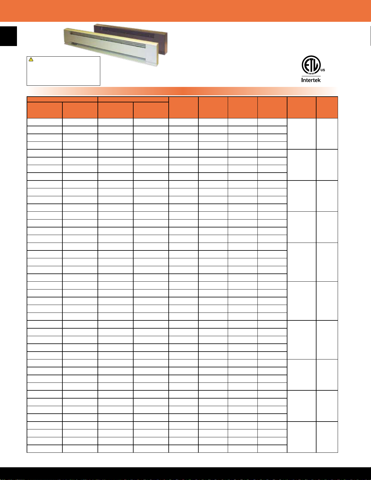
3700 Series Architectural Style Electric Baseboard Heater
62
!
WARNING: This product can expose you
to chemicals including nickel which is known
to the State of California to cause cancer,
and chromium, which is known to the State
of California to cause birth defects and/or
reproductive harm. For more information go
to www.P65Warnings.ca.gov.
STANDARD WHITE COMMERCIAL BROWN
MFG CATALOG
NUMBER
01160002 E3703-024 01164302 E3703-024B 375 1275 120 3.1
01160102 F3703-024 01164402 F3703-024B 375 1275 208 1.8
01160202 H3703-024 01164502 H3703-024B 375 / 281 1275 / 955 240 / 208 1.6/1.4
01160302 G3703-024 01164602 G3703-024B 375 / 281 1275 / 955 277 / 240 1.6/1.2
01160402 E3705-028 01164702 E3705-028B 500 1706 120 4.2
01160502 F3705-028 01164802 F3705-028B 500 1706 208 2.4
01160602 H3705-028 01164902 H3705-028B 500 / 375 1706 / 1275 240 / 208 2.1/1.8
01160702 G3705-028 01165002 G3705-028B 500 / 375 1706 / 1275 277 / 240 1.8/1.6
01160802 E3706-036 01165102 E3706-036B 600 2040 120 5
01160902 F3706-036 01165202 F3706-036B 600 2040 208 2.9
01161002 H3706-036 01165302 H3706-036B 600 / 450 2040 / 1530 240 / 208 2.5/2.2
01161102 G3706-036 01165402 G3706-036B 600 / 450 2040 / 1530 277 / 240 2.2/1.9
01161202 E3707-040 01165502 E3707-040B 750 2550 120 6.3
01161302 F3707-040 01165602 F3707-040B 750 2550 208 3.6
01161402 H3707-040 01165702 H3707-040B 750 / 563 2550 / 1914 240 / 208 3.1/2.7
01161502 G3707-040 01165802 G3707-040B 750 / 563 2550 / 1914 277 / 240 2.7.2.6
01161602 E3710-048 01165902 E3710-048B 1000 3413 120 8.3
01161702 F3710-048 01166002 F3710-048B 1000 3413 208 4.8
01161802 H3710-048 01166102 H3710-048B 1000 / 750 3413 / 2550 240 / 208 4.2/3.6
01161902 G3710-048 01166202 G3710-048B 1000 / 750 3413 / 2550 277 / 240 3.6/3.1
01162002 G3707-048 01166302 G3707-048B 750 2550 277 3.4
01162102 E3712-060 01166402 E3712-060B 1250 4250 120 10.4
01162202 F3712-060 01166502 F3712-060B 1250 4250 208 6
01162302 H3712-060 01166602 H3712-060B 1250 / 938 4250 / 3189 240 / 208 5.2/4.5
01162402 G3712-060 01166702 G3712-060B 1250 / 938 4250 / 3189 277 / 240 4.5/3.9
01162502 G3709-060 01166802 G3709-060B 938 3189 277 3.4
01162602 E3715-072 01166902 E3715-072B 1500 5100 120 12.5
01162702 F3715-072 01167002 F3715-072B 1500 5100 208 7.2
01162802 H3715-072 01167102 H3715-072B 1500 / 1125 5100 / 3825 240 / 208 6.3/4.7
01162902 G3715-072 01167202 G3715-072B 1500 / 1125 5100 / 3825 277 / 240 5.4/4.7
01163002 G3711-072 01167302 G3711-072B 1125 3825 277 4.1
01163102 F3717-084 01167402 F3717-084B 1750 5950 208 8.4
01163202 H3717-084 01167502 H3717-084B 1750 / 1313 5950 / 4464 240 / 208 7.3/6.3
01163302 G3717-084 01167602 G3717-084B 1750 / 1313 5950 / 4464 277 / 240 6.3/5.5
01163402 G3713-084 01167702 G3713-084B 1313 4464 277 4.7
01163502 F3720-096 01167802 F3720-096B 2000 6826 208 9.6
01163602 H3720-096 01167902 H3720-096B 2000 / 1500 6826 / 5100 240 / 208 8.3/7.2
01163702 G3720-096 01168002 G3720-096B 2000 / 1500 6826 / 5100 277 / 240 7.2/6.3
01163802 G3715-096 01168102 G3715-096B 1500 5100 277 5.4
01163902 F3725-120 01168202 F3725-120B 2500 8532 208 12
01164002 H3725-120 01168302 H3725-120B 2500 / 1875 8532 / 6375 240 / 208 10.4/9.0
01164102 G3725-120 01168402 G3725-120B 2500 / 1875 8532 / 6375 277 / 240 9.0/7.8
01164202 G3718-120 01168502 G3718-120B 1875 6375 277 6.8
Note: Refer to 3900 Series for product dimension specication
MFG MODEL
NUMBER
MFG CATALOG
NUMBER
Standard Models
MFG MODEL
NUMBER
• Available in white or brown with stainless steel
heating element and aluminum ns
• Powder coated 12 gauge heavy duty extruded Aluminum housing
construction with junction boxes located on each end of the unit
• An automatic thermal linear limit is used
along the entire heated length of the unit
• Wire guard extends along the entire
outlet area of the baseboard
• Special colors available, consult factory
• Made in U.S.A.
WATTS BTUs VOLTS AMPS
HEATER
LENGTH
(IN.)
24 14
28 16
36 22
40 27
48 31
60 33
72 41
84 49
96 58
120 67
WT.
(LBS)
Page 64

Hydronic & Architectural Electric Baseboard Heater Accessories
Product Specications
• The entire heater casing shall be constructed of 6063 extruded Aluminum. Minimum thickness of .100” (12 gauge) Aluminum shall be
acceptable. Outlet grill shall cover entire length of air discharge opening and be constructed of steel. All casing and grill construction shall be
painted with high quality durable powder coated paint.
• The heating element shall be high quality nichrome wire encased in Magnesium Oxide and sealed in a stainless steel tube.
• Linear automatic thermal limit shall extend the entire heater length of element and protect heater in case of an over-temperature condition.
• Optional controls shall be mounted in junction box enclosures at either end of heater. Optional integral thermostat shall be located in junction
box with adjustment knob or for tamper-proof operation. Optional disconnect switch shall be mounted in junction box. Optional 120 Volt or air
conditioning receptacle shall be mounted in junction box.
• Optional installation accessories shall include inside and outside corner sections for complete wall perimeter t. Prole of corners and grill shall
have appearance of heat sections for continuous architectural design. Corner accessories and heater sections shall be secured by alignment pins
for easy alignment of multiple heater applications.
Field Installed Accessories
Standard White Commercial Brown
DESCRIPTION
Single Pole, In-Built T-Stat, 22A @ 120-240V;
18A @ 277V; 0°-110° F
Double Pole, In-Built T-Stat, 22A @ 120-240V;
18A @ 277V; 0°-110° F
Air Conditioning Receptacle Section, 20 Amp @ 125-277V 01118902 3900AC 01119902 3900ACC
120V. Receptacle Section, 15 Amp 01119002 3900REC 01120002 3900RECC
MFG
CATALOG
NUMBER
MFG
MODEL
NUMBER
MFG
CATALOG
NUMBER
MFG
MODEL
NUMBER
01118702 3900T1 01119502 3900T1C
01118802 3900T2 01119602 3900T2C
63
Disconnect Switch, 20 Amp @ 125-277VAC; DPST 01119402 3900DS 01120402 3900DSC
OUTSIDE
CORNER
INSIDE
CORNER
Outside and inside corner
sections are 6” on longest side
!
WARNING: This product can expose you
to chemicals including nickel which is known
to the State of California to cause cancer,
and chromium, which is known to the State
of California to cause birth defects and/or
reproductive harm. For more information go
to www.P65Warnings.ca.gov.
3.00”
Baseboard Sections
STANDARD WHITE COMMERCIAL BROWN DESCRIPTION
MFG
CATALOG
NUMBER
MFG
MODEL
NUMBER
MFG
CATALOG
NUMBER
MFG
MODEL
NUMBER
SECTION SIZE
01121502 39BS28 0112215 39BS28C
01121602 39BS36 0112222 39BS36C 36”
01121702 39BS48 0112239 39BS48C 48”
01121802 39BS60 0112246 39BS60C 60”
Blank Section
01121902 39BS72 0112253 39BS72C 72”
01122002 39BS96 0112260 39BS96C 96”
01150902 39BS120 0115100 39BS120C 120”
01119102 3900-ICS 0112017 3900-ICSC Inside Corner
01119202 3900-OCS 0112024 3900-OCSC Outside Corner
01119302 3900-CS 01120302 3900-CSC Control Section 4” Blank
Wireway Covers (White Units Only)Dimension
TEMPERATURE LIMITING DEVICE
MFG
CATALOG
NUMBER
MFG
MODEL
NUMBER
LENGTH
01122802 3900WW28 28” 2
28”
-
WT.
(LBS)
4.10
1.43
1.60
2.42
8.50”
WIRE NUT
01122902 3900WW36 36” 2.5
01123002 3900WW48 48” 3.5
01123102 3900WW60 60” 4.5
01123202 3900WW72 72” 5.5
01123302 3900WW96 96” 7.5
01151102 3900WW120 120” 7.5
2.1
Page 65

2900S Series Electric Baseboard - Stainless Steel Element Convection Heater
64
!
WARNING: This product can expose you
to chemicals including nickel which is known
to the State of California to cause cancer,
and chromium, which is known to the State
of California to cause birth defects and/or
reproductive harm. For more information go
to www.P65Warnings.ca.gov.
IVORY WHITE
MFG CATALOG
NUMBER
01043002 E2903-024S 01049902 E2903-024SW 375 1275 120 3.1
01043102 F2903-024S 01050002 F2903-024SW 375 1275 208 1.8
01043202 H2903-024S 01050102 H2903-024SW 375 / 281 1275 / 955 240 / 208 1.6/1.4
01043302 G2903-024S 01050202 G2903-024SW 375 / 281 1275 / 955 277 / 240 1.6/1.2
01043402 E2905-028S 01050302 E2905-028SW 500 1706 120 4.2
01043502 F2905-028S 01050402 F2905-028SW 500 1706 208 2.4
01043602 H2905-028S 01050502 H2905-028SW 500 / 375 1706 / 1275 240 / 208 2.1/1.8
01043702 G2905-028S 01050602 G2905-028SW 500 / 375 1706 / 1275 277 / 240 1.8/1.6
01043802 E2906-036S 01050702 E2906-036SW 600 2040 120 5
01043902 F2906-036S 01050802 F2906-036SW 600 2040 208 2.9
01044002 H2906-036S 01050902 H2906-036SW 600 / 450 2040 / 1530 240 / 208 2.5/2.2
01044102 G2906-036S 01051002 G2906-036SW 600 / 450 2040 / 1530 277 / 240 2.2/1.9
01044202 E2907-040S 01051102 E2907-040SW 750 2550 120 6.3
01044302 F2907-040S 01051202 F2907-040SW 750 2550 208 3.6
01044402 H2907-040S 01051302 H2907-040SW 750 / 563 2550 / 1914 240 / 208 3.1/2.7
01044502 G2907-040S 01051402 G2907-040SW 750 / 563 2550 / 1914 277 / 240 2.7.2.6
01044602 E2910-048S 01051502 E2910-048SW 1000 3413 120 8.3
01044702 F2910-048S 01051602 F2910-048SW 1000 3413 208 4.8
01044802 H2910-048S 01051702 H2910-048SW 1000 / 750 3413 / 2550 240 / 208 4.2/3.6
01044902 G2910-048S 01051802 G2910-048SW 1000 / 750 3413 / 2550 277 / 240 3.6/3.1
01045002 G2907-048S 01051902 G2907-048SW 750 2550 277 3.4
01045102 E2912-060S 01052002 E2912-060SW 1250 4250 120 10.4
01030002 F2912-060S 01052102 F2912-060SW 1250 4250 208 6
01030102 H2912-060S 01052202 H2912-060SW 1250 / 938 4250 / 3189 240 / 208 5.2/4.5
01030202 G2912-060S 01052302 G2912-060SW 1250 / 938 4250 / 3189 277 / 240 4.5/3.9
01030302 G2909-060S 01052402 G2909-060SW 938 3189 277 3.4
01030402 E2915-072S 01052502 E2915-072SW 1500 5100 120 12.5
01030502 F2915-072S 01052602 F2915-072SW 1500 5100 208 7.2
01030602 H2915-072S 01052702 H2915-072SW 1500 / 1125 5100 / 3825 240 / 208 6.3/4.7
01030702 G2915-072S 01052802 G2915-072SW 1500 / 1125 5100 / 3825 277 / 240 5.4/4.7
01030802 G2911-072S 01052902 G2911-072SW 1125 3825 277 4.1
01030902 F2917-084S 01053002 F2917-084SW 1750 5950 208 8.4
01031002 H2917-084S 01053102 H2917-084SW 1750 / 1313 5950 / 4464 240 / 208 7.3/6.3
01031102 G2917-084S 01053202 G2917-084SW 1750 / 1313 5950 / 4464 277 / 240 6.3/5.5
01031202 G2913-084S 01053302 G2913-084SW 1313 4464 277 4.7
01031302 F2920-096S 01053402 F2920-096SW 2000 6826 208 9.6
01031402 H2920-096S 01053502 H2920-096SW 2000 / 1500 6826 / 5100 240 / 208 8.3/7.2
01031502 G2920-096S 01053602 G2920-096SW 2000 / 1500 6826 / 5100 277 / 240 7.2/6.3
01031602 G2915-096S 01053702 G2915-096SW 1500 5100 277 5.4
01032102 F2925-120S 01054202 F2925-120SW 2500 8532 208 12
01032202 H2925-120S 01054302 H2925-120SW 2500 / 1875 8532 / 6375 240 / 208 10.4/9.0
01032302 G2925-120S 01054402 G2925-120SW 2500 / 1875 8532 / 6375 277 / 240 9.0/7.8
01032402 G2918-120S 01054502 G2918-120SW 1875 6375 277 6.8
MFG CATALOG
NUMBER
01157602 M2903-24AWi
01157702 H2903-24AWi 240
01157802 M2905-28AWi
01159702 H2905-28AWi 240
01158002 M2906-36AWi
01158102 H2906-36AWi 240
01158202 M2907-40AWi
01158302 H2907-40AWi 240
01158402 M2910-48AWi
01158502 H2910-48AWi 240
01158602 M2912-60AWi
01158702 H2912-60AWi 240
01158802 M2915-72AWi
01158902 H2915-72AWi 240
01159002 M2917-84AWi
01180002 H2917-84AWi 240
01180302 M2925-120AWi
01180402 H2920-120AWi 240
Note: Wireway length is the same as baseboard length.
MFG MODEL
NUMBER
WHITE
MFG MODEL
NUMBER
MFG CATALOG
NUMBER
2900A Series - International Models
• Available in white or ivory with stainless steel heating element and Aluminum ns
• Painted 22 gauge steel front with 20 gauge junction boxes located on each end of the
heater - junction boxes contain quick connect cable clamps and 6”ground lead wires
• Over-temperature thermal limit extends entire length of heated area
• A full length wireway provided along the back of the heater - enclosed conduit available
• Heater can be mounted to the wall by using the
key hole knockouts every 4” at the back of the heater
• Optional In-Built thermostats eld installed in the junction box
• For high altitude applications, delete the SW in the model number
and add HAW
• Height: 6” Depth: 2 1⁄2”
• Made in U.S.A.
Standard Models
MFG MODEL
NUMBER
WATTS BTUs VOLTS
375 1275
500 1706
600 2040
750 2550
1000 3413
1250 4250
1500 5100
1750 5950
2500 8532
WATTS BTUs VOLTS AMPS
220
220
220
220
220
220
220
220
220
HEATER LENGTH
(IN)
24” 10
28” 11
36” 11.5
40” 13
48” 14
60” 16
72” 19
84” 22
120” 31
HEATER
LENGTH (IN)
24 5
28 6
36 7
40 8
48 10
60 12
72 14
84 16
96 18
120 22
WT.
(LBS)
WT.
(LBS)
Page 66

2900C Series Electric Baseboard - Heavy Duty Commercial Convection Heater
• Bankers bronze with stainless steel heating element and Aluminum ns
• Powder coated 22 gauge steel front with 20 gauge junction boxes located on
each end of the heater - junction boxes contain quick connect cable clamps and
6” ground lead wires
• Standard inlet and outlet wire guards
• Over-temperature thermal limit extends entire heated length of unit
!
WARNING: This product can expose you
to chemicals including nickel which is known
to the State of California to cause cancer,
and chromium, which is known to the State
of California to cause birth defects and/or
reproductive harm. For more information go
to www.P65Warnings.ca.gov.
MFG CATALOG
NUMBER
01038302 E2903-024C 375 1275 120 3.1
01038402 F2903-024C 375 1275 208 1.8
01038502 H2903-024C 375 / 281 1275 / 955 240 / 208 1.6 / 1.4
01038602 G2903-024C 375 / 281 1275 / 955 277 / 240 1.6 / 1.2
01038702 E2905-028C 500 1706 120 4.2
01038802 F2905-028C 500 1706 208 2.4
01038902 H2905-028C 500 / 375 1706 / 1275 240 / 208 2.1 / 1.8
01039002 G2905-028C 500 / 375 1706 / 1275 277 / 240 1.8 / 1.6
01039102 E2906-036C 600 2040 120 5.0
01039202 F2906-036C 600 2040 208 2.9
01039302 H2906-036C 600 / 450 2040 / 1530 240 / 208 2.5 / 2.2
01039402 G2906-036C 600 / 450 2040 / 1530 277 / 240 2.2 / 1.9
01039502 E2907-040C 750 2550 120 6.3
01039602 F2907-040C 750 2550 208 3.6
01039702 H2907-040C 750 / 563 2550 / 1914 240 / 208 3.1 / 2.7
01039802 G2907-040C 750 / 563 2550 / 1914 277 / 240 2.7 / 2.6
01039902 E2910-048C 1000 3413 120 8.3
01040002 F2910-048C 1000 3413 208 4.8
01040102 H2910-048C 1000 / 750 3413 / 2550 240 / 208 4.2 / 3.6
01040202 G2910-048C 1000 / 750 3413 / 2550 277 / 240 3.6 / 3.1
01040302 G2907-048C 750 2550 277 3.4
01040402 E2912-060C 1250 4250 120 10.4
01040502 F2912-060C 1250 4250 208 6.0
01040602 H2912-060C 1250 / 938 4250 / 3189 240 / 208 5.2 / 4.5
01040702 G2912-060C 1250 / 938 4250 / 3189 277 / 240 4.5 / 3.9
01040802 G2909-060C 938 3189 277 3.4
01040902 E2915-072C 1500 5100 120 12.5
01041002 F2915-072C 1500 5100 208 7.2
01041102 H2915-072C 1500 / 1125 5100 / 3825 240 / 208 6.3 / 4.7
01041202 G2915-072C 1500 / 1125 5100 / 3825 277 / 240 5.4 / 4.7
01041302 G2911-072C 1125 3825 277 4.1
01041402 F2917-084C 1750 5950 208 8.4
01041502 H2917-084C 1750 / 1313 5950 / 4464 240 / 208 7.3 / 6.3
01041602 G2917-084C 1750 / 1313 5950 / 4464 277 / 240 6.3 / 5.5
01041702 G2913-084C 1313 4464 277 4.7
01041802 F2920-096C 2000 6826 208 9.6
01041902 H2920-096C 2000 / 1500 6826 / 5100 240 / 208 8.3 / 7.2
01042002 G2920-096C 2000 / 1500 6826 / 5100 277 / 240 7.2 / 6.3
01042102 G2915-096C 1500 5100 277 5.4
01042602 F2925-120C 2500 8532 208 12.0
01042702 H2925-120C 2500 / 1875 8532 / 6375 240 / 208 10.4 / 9.0
01042802 G2925-120C 2500 / 1875 8532 / 6375 277 / 240 9.0 / 7.8
01042902 G2918-120C 1875 6375 277 6.8
MFG CATALOG
NUMBER
01180502 M2903-024CI
01180602 H2903-024CI 240 240
01180702 M2905-028CI
01180802 H2905-028CI 240 2.1
01180902 M2906-036CI
01181002 H2906-036C 240 2.5
01181102 M2907-040CI
01181202 H2907-040C 240 3.1
01181302 M2910-048CI
01181402 H2910-048CI 240 4.2
01181502 M2912-060CI
01181602 H2912-060C 240 5.2
01181702 M2915-072CI
01181802 H2915-072CI 240 6.3
01181902 M2917-084CI
01182002 H2917-084CI 240 7.3
01182102 M2920-096CI
01182202 H2920-096CI 240 8.3
01182302 M2925-120CI
01182402 H2925-120CI 240 10.4
MFG MODEL
NUMBER
MFG MODEL
NUMBER
WATTS BTUs VOLTS AMPS
WATTS BTUs VOLTS AMPS
375 1275
500 1706
600 2040
750 2550
1000 3413
1250 4250
1500 5100
1750 5950
2000 6826
2500 8532
• A full length wireway provided along the back of the heater
• Heater can be mounted to the wall by using the key hole knockouts every 4” at
the back of the heater
• Optional In-Built thermostats eld installed in the junction box
• Height: 6” Depth: 2 1⁄2”
• Made in U.S.A.
Standard Models
HEATER
LENGTH (IN)
24 5
28 6
36 7
40 8
48 10
60 12
72 14
84 16
96 18
120 22
WT.
(LBS)
International Models
220 1.7
220 2.3
220 2.7
220 3.4
220 4.6
220 5.7
220 6.8
220 8.0
220 9.1
220 11.4
HEATER LENGTH
(IN)
24 5
28 6
36 7
40 8
48 10
60 12
72 14
84 16
96 18
120 22
WT.
(LBS)
65
Page 67

Electric Baseboard - Accessories
In-Built Thermostat Kits
66
MFG CATALOG
NUMBER
MFG MODEL
NUMBER
DESCRIPTION
01054602C TBS SPST-In-Built 22A @ 120-240V 18A @ 277V (0
01054702C TBD DPST-In-Built 22A @ 120-240V 18A @ 277V (0O-110FO)
*Junction box covers supplied with baseboard heater will work in conjunction with in-built thermostat kits.
Field Installed Accessories
O
-110FO)
WT.
(LBS)
½
½
!
WARNING: This product can expose you
to chemicals including nickel which is known
to the State of California to cause cancer,
and chromium, which is known to the State
of California to cause birth defects and/or
reproductive harm. For more information go
to www.P65Warnings.ca.gov.
IVORY WHITE BANKERS BRONZE
DESCRIPTION
Disconnect Switch,
20 Amp, 120-277V
MFG CATALOG
NUMBER
01061002 DS 01061102 DSW 01061202 DSB
MFG MODEL
NUMBER
MFG CATALOG
NUMBER
MFG MODEL
NUMBER
MFG CATALOG
NUMBER
Corner Sections 01054902 CS 01055002 CSW 01055102 CSB
1” Joiner Kits 01055202 JK 01055302 JKW 01055402 JKB
6” Blank Relay Section
(Relay Not Included)**
01055502 LVRS 01055602 LVRSW 01055702 LVRSB
Receptacle Section
(Baseboard Mounted)
01055802 BDR115 01055902 BDR115W 01056002 BDR115B
15 Amp 120 VAC
Receptacle Section
(Mounted in 6” Blank)
01056102 DR115 01056202 DR115W 01056302 DR115B
15 Amp 120 VAC
Transfer Switch
(Mounted in 6” Blank) 1
01056402 SR120 01056502 SR120W 01056602 SR120B
6 Amp 120 VAC
Transfer Switch
(Mounted in 6” Blank)
01056702 SR220 01056802 SR220W 01056902 SR220B
16 Amp 240 VAC
**Not for use with 24A06G-1 relay
!
WARNING: This product can expose you
to chemicals including nickel which is known
to the State of California to cause cancer,
and chromium, which is known to the State
of California to cause birth defects and/or
reproductive harm. For more information go
to www.P65Warnings.ca.gov.
MFG MODEL
NUMBER
WT.
(LBS)
1
¼
½
1
¼
2
Optional Wireway Covers
MFG
CATALOG
NUMBER
01057002 WWA01 24” 20 1
01057102 WWA02 28” 24 1.5
01057202 WWA03 36” 32 2
01057302 WWA04 40” 36 2.5
01057402 WWA05 48” 44 3
01057502 WWA06 60” 56 4
01057602 WWA07 72” 68 5
01057702 WWA08 84” 80 6
01057802 WWA09 96” 92 7
01057902 WWA00 120” 116 8
MFG
MODEL
NUMBER
!
WARNING: This product can expose you
to chemicals including nickel which is known
to the State of California to cause cancer,
and chromium, which is known to the State
of California to cause birth defects and/or
reproductive harm. For more information go
to www.P65Warnings.ca.gov.
LENGTH
(in.)
COVER
LENGTH
(in.)
WT.
(LBS)
Blank Sections
IVORY WHITE BANKERS BRONZE
LENGTH
MFG
CATALOG
NUMBER
24” 01058002 BBS024A 01059002
28” 01058102 BBS028A 01059102
36” 01058202 BBS036A 01059202
40” 01058302 BBS040A 01059302
48” 01058402 BBS048A 01059402
60” 01058502 BBS060A 01059502
72” 01058602 BBS072A 01059602
84” 01058702 BBS084A 01059702
96” 01058802 BBS096A 01059802
120” 01058902 BBS120A 01059902
MFG
MODEL
NUMBER
!
WARNING: This product can expose you
to chemicals including nickel which is known
to the State of California to cause cancer,
and chromium, which is known to the State
of California to cause birth defects and/or
reproductive harm. For more information go
to www.P65Warnings.ca.gov.
MFG
CATALOG
NUMBER
MFG
MODEL
NUMBER
BBS024AW
BBS028AW
BBS036AW
BBS040AW
BBS048AW
BBS060AW
BBS072AW
BBS084AW
BBS096AW
BBS120AW
MFG
CATALOG
NUMBER
MFG
MODEL
NUMBER
WT.
(LBS)
01060002 BBS024C 5
01060102 BBS028C
5
01060202 BBS036C 6
01060302 BBS040C 7
01060402 BBS048C 8
01060502 BBS060C 10
01060602 BBS072C 12
01060702 BBS084C 15
01060802 BBS096C 17
01060902 BBS120C 20
½
Page 68

Infrared Electric Heaters - General Product Information
The largest selection of overhead electric infrared heaters in the industry today!
Flat Panel Emitter Heaters
• High-density, medium wavelength radiant heat emitter for indoor heating applications
• Shipped fully assembled with wire guard and standard 60° symmetric heat pattern
• Flat panel emitter operates at 78.5% radiant efciency & generates no lumen glare
• Designed for indoor heating applications or protected outdoor areas
• Life expectancy of 25,000 hours
!
WARNING: This product can expose you
to chemicals including nickel which is known
to the State of California to cause cancer,
FSS Series
and chromium, which is known to the State
of California to cause birth defects and/or
reproductive harm. For more information go
to www.P65Warnings.ca.gov.
FSA Series
67
• Gold anodized aluminum housing
• Designed for rugged industrial applications
• Chain or suspension mounting options
• Extruded aluminum housing
• Designed for commercial applications
• Chain, suspension, wall, or recessed
mounting options
Quartz Lamp Mul-T-Mount Heaters
• Short wavelength radiant heat emitter for indoor & total exposed outdoor heating applications
• Gold anodized interior reector offered in symmetrical or asymmetrical heat pattern options
• Clear quartz lamp operates at 96% radiant efciency & generates 8-lumens per watt
• Designed for indoor and totally exposed outdoor heating application areas
• Element life expectancy of 5,000 hours
!
WARNING: This product can expose you
to chemicals including nickel which is known
to the State of California to cause cancer,
and chromium, which is known to the State
TH/THSS Series &
TH/THSS-AG Series
of California to cause birth defects and/or
reproductive harm. For more information go
to www.P65Warnings.ca.gov.
THA Series
• Housing nish: bankers bronze or stainless steel
• Designed for rugged industrial applications
• Chain, suspension, wall, or recessed
mounting options
• Shipped with clear quartz lamp
• AG sufx models include “glare” reducing sleeves
• Extruded aluminum housing
• Nickel gray nish
• Designed for commercial applications
• Chain or suspension mounting options
• Shipped with clear quartz lamps and
amber gray “glare” reducing sleeves
Page 69

Infrared Electric Heaters - General Product Information
68
Types of Electric Infrared Application & Sizing Details
• Indoor Spot Heating
Average: 25-60 watts per square foot
Calculation: Sq.ft. x desired temperature rise = total watts required
• Total Area / Building Heating
Average: 8-20 watts per square foot
Calculation: Sq.ft. x . 5 x desired temperature rise = total watts required
• Outdoor Spot Heating
Average: 2 watts per square foot per desired temperature rise
Calculation: Sq.ft. x 2 x desired temperature rise = total watts required
• Outdoor Snow & Ice Control Heating System
Average: 85-110 watts per square foot
Calculation: Sq.ft. x required watts / sq.ft. = total watts required
Quartz Lamp Glare Reduction Options
12mm Clear Quartz Lamp
• Approximately 96% radiant efcient
• 8 lumens per watt on a 3200 watt xture, equals 25,600 lumens
• Can be mounted 10’ and above indoors, 8’ to 10’ outdoors
• Emits a bright light, but extremely energy efcient site of installation
12mm Red Vycor Sleeve
• Slips over 12mm quartz lamp to reduce glare
• Filters approximately 90% of visible light
• Allows 90% of the energy to pass through to installed area
• Reduces 90% of the clear quartz lumens
8mm Clear Quartz Lamp with Amber Gray Sleeve
• When used together, reduces 94% of lumens of clear quartz lamp
• Allows 90% of energy to pass through sleeve to installed area
• Eliminates red glow found with using red vycor sleeve
• Shipped standard on all AG sufx & THA model series
Page 70

FSS Series Heavy Duty Flat Panel Emitter Electric Overhead Infrared Heater
Heavy Duty Overhead Infrared Heaters for Indoor Spot Heating,
Zone, or Total Area Heating Applications
• High-density, medium wavelength radiant heat, with 60°
symmetric heat pattern
• Flat panel emitter operates at a radiant efciency of 78.5%
• Non-glare, uniform heat generating directional heat pattern
• Rugged steel structure surrounds emitter element, great for
FSS-14
FSS-31
high vibration areas
• Gold anodized aluminum housing for efcient, long term
reectivity & corrosion resistance
• Single or three phase wiring on select models
• “ L” brackets included for chain suspension, or rigid mounting
• Field wiring box mounted on each heater
• Heavy duty wire guard factory installed
• 25,000 hour element life expectancy
• Shipped fully assembled
FSS-43
!
WARNING: This product can expose you
to chemicals including nickel which is known
to the State of California to cause cancer,
and chromium, which is known to the State
of California to cause birth defects and/or
reproductive harm. For more information go
to www.P65Warnings.ca.gov.
• Made in U.S.A.
Standard Models
MFG
CATALOG
NUMBER
04881502 FSS-1412-1
04881602 FSS-1420-1 208 1 6.97
04881702 FSS-1424-1 240 1 6.04
04881802 FSS-1427-1 277 1 5.23
04881902 FSS-1448-1 480 1 3.02
04882002 FSS-1457-1 600 1 2.52
04882102 FSS-3120-1
04882202 FSS-3124-1 240 1 13.13
04882302 FSS-3127-1 277 1 11.37
04882402 FSS-3148-1 480 1 6.56
04882502 FSS-3157-1 600 1 5.48
04882602 FSS-4320-3
04882702 FSS-4324-3 240 1 or 3 17.91 10.36
04882802 FSS-4327-1 277 1 15.52
04882902 FSS-4348-3 480 1 or 3 8.96 5.18
04883002 FSS-4357-3 600 1 or 3 7.48 4.32
04883102 FSS-9520-3
04883202 FSS-9524-3 240 1 or 3 39.6 22.89
04883302 FSS-9527-1 277 1 34.3
04883402 FSS-9548-3 480 1 or 3 19.8 11.44
04883502 FSS-9557-3 600 1 or 3 16.5 9.54
04883602 FSS95TMK TANDEM MOUNTING KIT 6
MFG
MODEL
NUMBER
WATTS VOLTS PHASE
120 1
1450
208 1
3150
208 1 or 3
4300
208 1 or 3
9500
BTUs /
Hr.
4947
10,748
14,672
32,414
AMPS
1-PH 3-PH
12.1
15.14
20.67 11.94
45.67 26.39
ELEMENTS
PER HEATER
1
WT.
(LBS)
7
13
18
31
FSS/FSA Replacement Elements
MFG CATALOG
NUMBER
01356002 64337-001
01356102 64337-002
01356202 64337-003
01356302 64337-004
01356402 64337-005
01356502 64337-006
01356602 64337-007
01356702 64337-008
01356802 64337-009
01356902 64337-010
01357002 64337-011
01357102 64337-012
01357202 64337-013
01357302 64337-014
01357402 64337-015
01357502 64337-016
01357602 64337-017
01357702 64337-018
01357802 64337-019
01357902 64337-020
01358002 64337-021
MFG MODEL
NUMBER
69
Suspension Heating Application
Spot Indoor Heaters
• Directional heating systems for
where and when you need it
• No element glare
• No glass materials
• Rigid housing & element structure
• Designed for rugged & dirty
environments
• Delivers higher and more uniform
heat output with less energy
consumption
• Ideal spot heating system for
high-bay buildings up to 24’
Page 71

C
FSS Series Heavy Duty Flat Panel Emitter Electric Overhead Infrared Heater
70
(2) FSS-95 heaters with TMK-95 tandem mounting kit
!
WARNING: This product can expose you
to chemicals including nickel which is known
to the State of California to cause cancer,
and chromium, which is known to the State
of California to cause birth defects and/or
FSS-95
reproductive harm. For more information go
to www.P65Warnings.ca.gov.
FSS Series Dimensions
A
B
MFG
MODEL
NUMBER
FSS-14 8
FSS-31 8
FSS-43 9
FSS-95 7
FSS-95 TANDEM 7
DEPTH
“A”
1
⁄2 9 26
1
⁄2 9 46
3
⁄4 20 29
3
⁄4 20 49
3
⁄4 20 108
DIMENSIONS (in.)
“B”
WIDTH
Mounting Clearances & Recommended Mounting Height
Required Minimum Mounting Clearances KW Recommended Mounting Height
FSS-14 and FSS-31 6" from ceiling
FSS-43 and FSS-95 24” from ceiling
36” from vertical surface & from another heater
72” from face of heater to combustible surface
FSS-95 Tandem Only 87” from face of heater to combustible surface (2) 9.5 15’ - 30’
Sizing Chart
Housing & Construction:
.040 Gold anodized Aluminum housing for efficient, long-term
reflectivity and corrosion resistance. High-density radiant heat.
Housing is ETL Listed for indoor, dry environment applications only.
Made in U.S.A.
Reflector:
60 degree symmetric heat pattern, reference the sizing chart to
determine overall coverage based on the mounting height.
Elements:
Heavy duty flat panel emitter. Available wattages in 1450, 3150,
4300 and 9500 Watts per element. Available in standard voltages
from 120 to 600 Volts.
Controls:
Flat panel emitter heaters are not manufactured with any control
device on the unit. All controls and accessories should be specified
as remote mounted. Please consult the technical sales department
of factory for help in determining applicable controls. Please follow
installation instructions that accompany each heater.
Accessories:
Power contactor panels.
MOUNTING
HEIGHT
8’
10’
12’
14’
16’
18’
20’
24’
30’
MFG
MODEL
NUMBER
FSS-14 8 8 64 22.7
FSS-31 9 8 72 43.8
FSS-14 11 10 11 0 13.2
FSS-31 11 10 11 0 28.6
FSS-43 12 10 120 35.8
FSS-31 12 11.5 138 22.8
FSS-43 14 12 168 25.6
FSS-95 15 13 195 48.7
FSS-43 16 14 224 19.2
FSS-95 18 16 288 33.0
FSS-43 18 16 288 14.9
FSS-95 21 18 378 25.1
FSS-95
TANDEM
FSS-95 23 20 460 20.7
FSS-95
TANDEM
FSS-95
TANDEM
FSS-95
TANDEM
FSS-95
TANDEM
LENGTH WIDTH
24 19 456 41.7
28 20 560 33.9
28 23 644 29.5
33 27 891 21.3
41 32 1312 14.5
COVERAGE
(SQ. FT.)
WATTS
(SQ.
FT.)
1.4 8’ - 10’
3.1 8’ - 12’
4.3 10’ - 14’
9.5 12’ - 16’
Product Specications
ICP Control Panels
Features
• NEMA 4 outdoor rated control box
• Door interlock disconnect switch
• Custom made to customers specications
• SCR and proportional controls optional
• Circuit breakers sized for heater load per stage
•
Please see ICP page to select panel to control
one or multiple units, if required.
!
WARNING: This product can expose you
to chemicals including nickel which is known
to the State of California to cause cancer,
and chromium, which is known to the State
of California to cause birth defects and/or
reproductive harm. For more information go
to www.P65Warnings.ca.gov.
“C”
LENGTH
Page 72

FSA Series Architectural Flat Panel Emitter Electric Overhead Infrared Heater
Architectural Overhead Infrared Heaters for Indoor Spot
Heating, Zone, or Total Area Heating Applications
FSA-14
FSA-31
FSA-43
• ETL C/US Listed for suspended high-bay indoor or protected
outdoor applications
• Designed for spot / zone or total area heating applications
• Heating elements included (Heavy Duty Single Flat Panel Emitter)
• Medium wave emitter operates at 78.5% radiant efciency - with a
25,000 hour life expectancy
• Extruded aluminum housing with a nickel-gray nish, providing a 60°
symmetrical heat pattern
• Electrical enclosure included for direct wire installation
• Single or three-phase wiring congurations
• “L” brackets included on the top of the heating housing for chain
suspension, wall mounting, or ceiling mounting options
• Units can be surface mounted, semi-recessed, or fully-recessed
• Zinc plated heavy-gauge safety grills included for all models
• Optional wall mounting bracket sold separately
• Shipped fully assembled and made in U.S.A.
FSA-95
!
WARNING: This product can expose you
to chemicals including nickel which is known
to the State of California to cause cancer,
and chromium, which is known to the State
of California to cause birth defects and/or
reproductive harm. For more information go
to www.P65Warnings.ca.gov.
71
Standard Models
MFG
CATALOG
NUMBER
04889002 FSA-1412-1
04889102 FSA-1420-1 208 6.97
04889202 FSA-1424-1 240 6.04
04889302 FSA-1427-1 277 5.23
04889402 FSA-1448-1 480 3.02
04889502 FSA-1457-1 600 2.52
04889602 FSA-3120-1
04889702 FSA-3124-1 240 13.13
04889802 FSA-3127-1 277 11.37
04889902 FSA-3148-1 480 6.56
04890002 FSA-3157-1 600 5.48
04890102 FSA-4320-3
04890202 FSA-4324-3 240 1 or 3 17.91 10.36
04890302 FSA-4327-1 277 1 15.52
MFG
MODEL
NUMBER
WATTS VOLTS PHASE
120
1450
208
3150
208 1 or 3
4300
1 4947
1 10,748
BTUs /
Hr.
14,672
AMPS
1-PH 3-PH
12.1
15.14
20.67 11.94
WT.
(LBS)
13
22
24
Optional Wall Mounting Brackets
CEILING
W
24"
(MIN.)
A
L
L
4"
(MIN.)
87"
(MIN.)
04890402 FSA-4348-3 480 1 or 3 8.96 5.18
04890502 FSA-4357-3 600 1 or 3 7.48 4.32
04890602 FSA-9520-3
04890702 FSA-9524-3 240 1 or 3 39.6 22.89
04890802 FSA-9527-1 277 1 34.3
04890902 FSA-9548-3 480 1 or 3 19.8 11.44
04891002 FSA-9557-3 600 1 or 3 16.5 9.54
9500
208 1 or 3
45.67 26.39
32,414
FLOOR
OPTIONAL WALL MOUNTING BRACKETS
MFG CATALOG NUMBER MFG MODEL NUMBER
39
04892002 FSA-14-31WMB
04892102 FSA-43-95WMB
Page 73

72
FSA Series Architectural Flat Panel Emitter Electric Overhead Infrared Heater
FSA Series Dimensions
FSA-14 / FSA-31
MFG
MODEL
NUMBER
FSA-14 9 5
“A”
DEPTH
DIMENSIONS (in.)
“B”
WIDTH
3
⁄4 26 1⁄16
“C”
LENGTH
All FSA Models
MOUNTING
HEIGHT
8’
10’
12’
14’
16’
FSA-43 / FSA-95
Mounting Clearances & Recommended Mounting Height
Mounting Clearances KW Recommended Mounting Height
24” from ceiling
36” from vertical surface & from another heater
(4” when using optional mounting bracket)
72” from face of heater to combustible surface
Sizing Chart
MFG
MODEL
NUMBER
FSA-14 8 8 64 22.7
FSA-31 9 8 72 43.8
FSA-14 11 10 110 13.2
FSA-31 11 10 110 28.6
FSA-43 12 10 120 35.8
FSA-31 12 11.5 138 22.8
FSA-43 14 12 168 25.6
FSA-95 15 13 195 48.7
FSA-43 16 14 224 19.2
FSA-95 18 16 288 33.0
FSA-43 18 16 288 14.9
FSA-95 21 18 378 25.1
LENGTH WIDTH
COVERAGE
(SQ. FT.)
WATTS
(SQ.
FT.)
FSA-31 9 5 3⁄4 47 1⁄16
FSA-43 9 1⁄4 14 3⁄4 25 1⁄16
FSA-95 9 1⁄4 14 3⁄4 47 1⁄16
1.4 8’ - 10’
3.1 8’ - 12’
4.3 10’ - 14’
9.5 12’ - 16’
Product Specications
Housing & Construction:
Extruded 6063 aluminum housing with protective grill. Powder
coat silver finish for excellent durability and attractive appearance
in commercial applications. ETL C/US listed for indoor, dry
environments. Made in USA.
Elements:
Heavy duty flat panel emitter. Available wattages in 1450, 3150,
4300 and 9500 Watts per element. Available in standard voltages
from 120 to 600 Volts.
*Note: Replacement elements located on FSS Series pages.
Controls:
Flat panel emitter heaters are not manufactured with any control
device on the unit. All controls and accessories should be specified
as remote mounted. Please consult the technical sales department
of factory for help in determining applicable controls. Please follow
installation instructions that accompany each heater.
Accessories:
Optional power controls pages 80-83.
Optional - ICP Control Panels
Features
• NEMA 4 outdoor rated control box
• Door interlock disconnect switch
• Custom made to customers specications
• SCR and proportional controls optional
• Circuit breakers sized for heater load per stage
•
See ICP page to select panel to control
one or multiple units, if required
!
WARNING: This product can expose you
to chemicals including nickel which is known
to the State of California to cause cancer,
and chromium, which is known to the State
of California to cause birth defects and/or
reproductive harm. For more information go
to www.P65Warnings.ca.gov.
Page 74
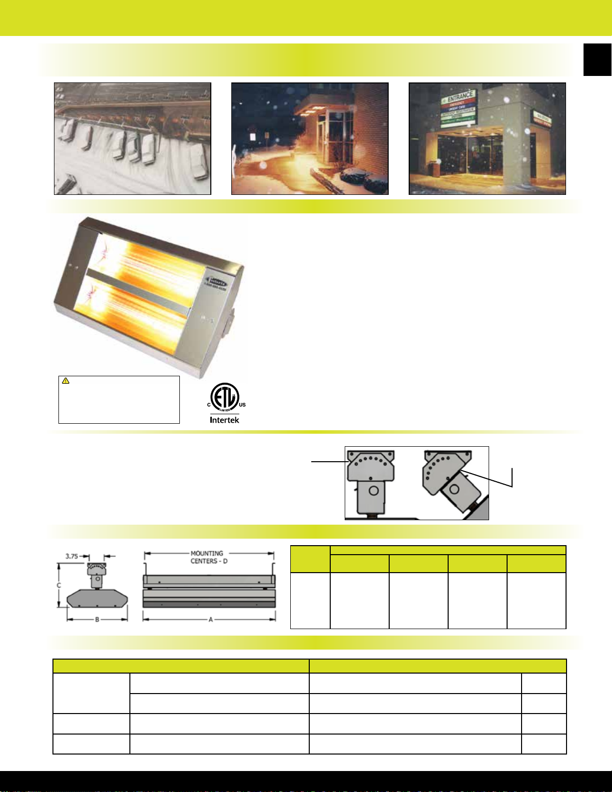
TH & THSS Series Mul-T-Mount Electric Infrared Heater
Overhead Infrared Heaters for Snow and Ice Control,
Outdoor Spot Heating, and All Indoor Heating Applications
Product Description
AVAILABLE IN 2 OR 3 LAMP BANKERS BRONZE
OR STAINLESS STEEL FINISH
• Listed for suspended, totally exposed (outdoor), high-bay (indoor)
comfort heating and exterior snow & ice control applications
• Listed for recessed applications
• 20 gauge powder coated steel or stainless steel housings
• Gold anodized Aluminum reectors & end caps
• 50% higher wattage densities for 3-element units
• 2-Lamp wiring, single phase
• 3-Lamp wiring, three or single phase
• Stainless steel models have non-corrosive housing, hardware
and brackets; no ferrous metals used in the unit. Durable in harsh
!
WARNING: This product can expose you
to chemicals including nickel which is known
to the State of California to cause cancer,
and chromium, which is known to the State
of California to cause birth defects and/or
reproductive harm. For more information go
to www.P65Warnings.ca.gov.
atmospheres & outdoor environments
• High temperature lead wires
• Clear 12mm diameter Quartz Lamp(s) Included
• Elements provide a bright light, generating 8-lumens per watt
• Made in U.S.A.
73
Features:
In-Built surface mounting
brackets allows for xture
adjustment up to 45°
horizontal tilt
In-built surface
mounting
brackets
attached to
the top wiring
channel
0 to 45
15o increments
Product Dimensions
MUL-T-
MOUNT
SERIES
222 24" 15" 11" 23
223 24" 21
342 33" 15" 11" 32 1⁄2"
343 33" 21 1⁄2" 11" 32 1⁄2”
462 46" 15" 11" 45 1⁄2"
463 46" 21
“A”
LENGTH
DIMENSIONS (IN.)
“B”
WIDTH
1
⁄2" 11" 23 1⁄2"
1
⁄2" 11" 45 1⁄2"
“C”
HEIGHT
MTG.CTR.
Mounting Clearances & Recommended Mounting Height
Mounting Clearances Recommended Mounting Height
2 & 3 Lamp
Models
2 Lamp Models 72” from face of heater to combustible surface 90° Symmetric Reector - Indoor 8’ - 12’
3” from ceiling 30° Symmetric & A30° Asymmetric Reector - Indoor 14’ - 30’
24” from vertical surface 60° Symmetric & A60° Asymmetric Reector - Indoor 12’ - 18’
o
tilt @
“D”
1
⁄2"
3 Lamp Models 96” from face of heater to combustible surface 30° Symmetric & A30° Asymmetric Reector - Outdoor 8’ - 10’
Page 75

74
TH & THSS Series Mul-T-Mount Electric Infrared Heater
30° Symmetric
60° Symmetric
90° Symmetric
30° Asymmetric
60° Asymmetric
Product SpecicationsReector Patterns
Series:
222, 342, 462 (Painted Version) 2-lamp –– TH Series
222, 342, 462 (Stainless Steel Version) 2-lamp –– THSS Series
223, 343, 463 (Stainless Steel Version) 3-lamp –– THSS Series
Housing:
20 gauge Galvanized Steel with baked on bankers bronze powder coated nish.
20 gauge Stainless Steel for durability and corrosion-resistance. Both housings
are ETL Listed for either indoor and totally exposed outdoor applications.
Reectors and End Caps:
.040 Gold anodized Aluminum reectors and end caps for superior reectivity.
Five choices of reector patterns including 30 degree narrow (symmetric &
asymmetric), 60 degree medium (symmetric & asymmetric), and 90 degree wide
(symmetric). THSS models have stainless steel endcaps.
Elements:
Clear quartz lamps. Coiled tungsten lament located within a sealed quartz
envelope, halogen lled, with porcelain end caps and 6” wire pigtail leads.
Elements are 12mm in diameter and deliver a 96% radiant efciency with high
moisture and thermal shock resistance. Instantaneous heat-up and cool-down
performance. Available wattages from 1600 to 3650 Watts per element. Available
voltages from 208 to 600 Volts.
Controls:
Mul-T-Mount heaters are not manufactured with any control device on the unit.
All controls are accessories and should be specied as such. Please consult the
technical sales department of factory for help in determining applicable controls.
Please follow installation instructions that accompany each heater.
Accessories:
Recessed mounting frames (painted or stainless steel), adjustable mounting
brackets (stainless steel only), vertical mounting brackets (stainless steel only),
wire guards, thermostats, snow detectors, SCR controllers, and power contactor
panels (ICP Series).
Sizing Chart
Mounting Heights (FT.) Watts Delivered per Square Foot
8 10 12 14 16 18 20
(kW)
Lamps
Reective
Pattern ( º)
30º 3.2
60º 3.2 10.5 x 9.5 13 x 12 15 x 14 17 x 16
90º 3.2 17 x 16 21 x 20 N / R N / R 11.8 7.6 - - - - -
30º 5.0 6 x 4 7.5 x 5.5 8.5 x 6.5 9.5 x 7.5 10.5 x 8.5 11.5 x 9.5 12.5 x 10.5 208.3 121.2 90.5 70.2 56.0 45.8 38.1
60º 5.0 11.5 x 9.5 14 x 12 16 x 14 18 x 16 20.5 x 18.5 23 x 21
90º 5.0 18 x 16 22 x 20 26 x 24 N / R N / R N / R 17.4 11.4 8.0 - - - -
30º 7.3 N / R 8.5 x 5.5 9.5 x 6.5 10.5 x 7.5 11.5 x 8.5 12.5 x 9.5 13.5 x 10.5 - 156.1 118.2 92.7 74.7 61.5 51.5
60º 7.3 12 x 10.5 15 x 12 17 x 14 19 x 16 21.5 x 18.5 24 x 21
90º 7.3 19 x 16 23 x 20 27 x 24 N / R N / R N / R 24.0 15.9 11.3 - - - -
30º 4.8
60º 4.8 10.5 x 10.5 13 x 13 15 x 15 17 x 17 21 x 21
90º 4.8 17 x 17 21 x 21 N / R N / R N / R 16.6 10.9 - - - - -
30º 7.5 N / R 7.5 x 6.5 8.5 x 7.5 9.5 x 8.5 10.5 x 9.5 11.5 x 10.5 12.5 x 11.5 - 153.8 117.6 92.9 75.2 62.1 52.2
60º 7.5 11.5 x 10.5 14 x 13 16 x 15 18 x 17 20.5 x 19.5 23 x 22
90º 7.5 18 x 17 22 x 21 26 x 25 N / R N / R N / R 24.5 16.2 11.5 - - - -
30º 10.95 N / R 8.5 x 6.5 9.5 x 7.5 10.5 x 8.5 11.5 x 9.5 12.5 x 10.5 13.5 x 11.5 - 198.2 153.7 122.7100.2 83.4 70.5
60º 10.95 12 x 11 15 x 13 17 x 15 19 x 17 21.5 x 19.5 24 x 22 N / R 83.0 56.2 42.9 33.9 26.1 20.7 -
90º 10.95 19 x 17 23 x 21 27 x 25 N / R N / R N / R N / R 33.9 22.7 16.2 - - - -
NOTE: This chart provides the same heat pattern coverage for all Mul-T-Mount Heater Series regardless of housing materials, added sleeve, or element diameter.
# of Qtz.
Heater Output
L x W L x W L x W L x W L x W L x W L x W
5.5 x 4 6.5 x 5.5 7.5 x 6.5 8.5 x 7.5 9.5 x 8.5 10.5 x 9.5 11.5 x 10.5
2 - Quartz Lamp Heaters
5.5 x 5 6.5 x 6.5 7.5 x 7.5 8.5 x 8.5 9.5 x 9.5 10.5 x 10.5 11.5 x 11.5 174.5 113.6 85.3 66.4 53.2 43.5 36.3
3 - Quartz Lamp Heaters
Heat Pattern Coverage at Floor Level
N / R N / R N / R
N / R
N / R
N / R N / R
N / R
145.5 89.5 65.6 50.2 39.6 32.1 26.5
32.1 20.5 15.2 11.8 - - -
45.8 29.8 22.3 17.4 13.2 10.4 -
57.9 40.6 30.7 24.0 18.4 14.5 -
43.5 28.4 21.3 16.6 10.9 - -
62.1 41.2 31.3
Mounting Heights (FT.)
8 10 12 14 16 18 20
24.5 18.8 14.8 -
Page 76

TH & THSS Series Mul-T-Mount Electric Infrared Heater
2-Lamp Mul-T-Mount Series Bankers Bronze Or
Stainless Steel With (2) Clear 12mm Quartz Lamps Included
BRONZE HOUSING STAINLESS STEEL HOUSING
MFG
CATALOG
NUMBER
04441602 222-30-TH-208V 04444002 222-30-THSS-208V
04441702 222-30-TH-240V 04444102 222-30-THSS-240V 240 63016249
04441802 222-30-TH-277V 04444202 222-30-THSS-277V 277 63016279
04813802 222-30-TH-480V 04814302 222-30-THSS-480V 480 63016489
04441902 222-A30-TH-208V 04444302 222-A30-THSS-208V 208
04442002 222-A30-TH-240V 04444402 222-A30-THSS-240V 240 63016249
04442102 222-A30-TH-277V 04444502 222-A30-THSS-277V 277 63016279
04814102 222-A30-TH-480V 04814602 222-A30-THSS-480V 480 63016489
04442202 222-60-TH-208V 04444602 222-60-THSS-208V 208
04442302 222-60-TH-240V 04444702 222-60-THSS-240V 240 63016249
04442402 222-60-TH-277V 04444802 222-60-THSS-277V 277 63016279
04813902 222-60-TH-480V 04814402 222-60-THSS-480V 480 63016489
04442502 222-A60-TH-208V 04444902 222-A60-THSS-208V 208
04442602 222-A60-TH-240V 04445002 222-A60-THSS-240V 240 63016249
04442702 222-A60-TH-277V 04445102 222-A60-THSS-277V 277 63016279
04814202 222-A60-TH-480V 04814702 222-A60-THSS-480V 480 63016489
04432902 222-90-TH-208V 04445202 222-90-THSS-208V 208
04442802 222-90-TH-240V 04445302 222-90-THSS-240V 240 63016249
04442902 222-90-TH-277V 04445402 222-90-THSS-277V 277 63016279
04814002 222-90-TH-480V 04814502 222-90-THSS-480V 480 63016489
04810802 342-30-TH-208V 04809302 342-30-THSS-208V
04810902 342-30-TH-240V 04809402 342-30-THSS-240V 240 63025249
88026143 342-30-TH-480V 88026394 342-30-THSS-480V 480 63025489
04811702 342-A30-TH-208V 04810202 342-A30-THSS-208V 208
04811802 342-A30-TH-240V 04810302 342-A30-THSS-240V 240 63025249
04443102 342-A30-TH-480V 04445602 342-A30-THSS-480V 480 63025489
04811102 342-60-TH-208V 04809602 342-60-THSS-208V 208
04811202 342-60-TH-240V 04809702 342-60-THSS-240V 240 63025249
88029143 342-60-TH-480V 88029394 342-60-THSS-480V 480 63025489
04812002 342-A60-TH-208V 04810502 342-A60-THSS-208V 208
04812102 342-A60-TH-240V 04810602 342-A60-THSS-240V 240 63025249
04443302 342-A60-TH-480V 04445802 342-A60-THSS-480V 480 63025489
04811402 342-90-TH-208V 04809902 342-90-THSS-208V 208
04811502 342-90-TH-240V 04810002 342-90-THSS-240V 240 63025249
88032144 342-90-TH-480V 88032394 342-90-THSS-480V 480 63025489
88027143 462-30-TH-480V 88027393 462-30-THSS-480V
04443602 462-A30-TH-480V 04446102 462-A30-THSS-480V 30° Asymmetrical 63036489
88030143 462-60-TH-480V 88030393 462-60-THSS-480V 7.3 60° Symmetrical 63036489
04443802 462-A60-TH-480V 04446302 462-A60-THSS-480V 60° Asymmetrical 63036489
88033144 462-90-TH-480V 88033394 462-90-THSS-480V 90° Symmetrical 63036489
NOTE: Consult the factory, the product instruction manual, or a licensed electrician for 3-phase wiring of all 2-element heaters.
MFG
MODEL
NUMBER
MFG
CATALOG
NUMBER
MFG
MODEL
NUMBER
KW BTUs VOLTS
208
3.2 10,922
208
5.0 17,065
24,915 480
REFLECTOR
PATTERN
30° Symmetrical
30° Asymmetrical
60° Symmetrical
60° Asymmetrical
90° Symmetrical
30° Symmetrical
30° Asymmetrical
60° Symmetrical
60° Asymmetrical
90° Symmetrical
30° Symmetrical 63036489
12 mm DIAMETER
REPLACEMENT
63016209
63016209
63016209
63016209
63016209
63025209
63025209
63025209
63025209
63025209
LAMP
75
WT.
(LBS)
20
25
32
Page 77
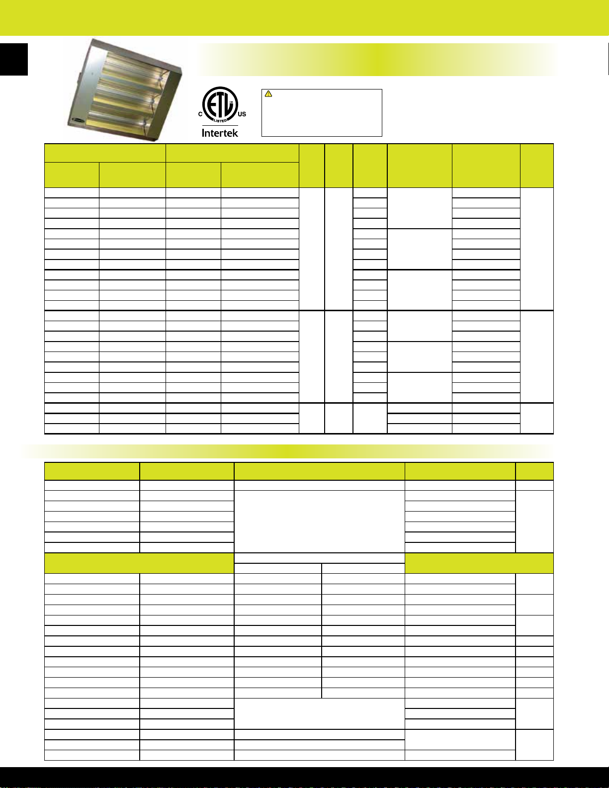
TH & THSS Series Mul-T-Mount Electric Infrared Heater
76
3-Lamp Mul-T-Mount Series - Bankers Bronze Or Stainless Steel Housing
With (3) Clear 12mm Quartz Lamps Included
!
WARNING: This product can expose you
to chemicals including nickel which is known
to the State of California to cause cancer,
and chromium, which is known to the State
of California to cause birth defects and/or
reproductive harm. For more information go
to www.P65Warnings.ca.gov.
BRONZE HOUSING STAINLESS STEEL HOUSING
MFG
CATALOG
NUMBER
MFG
MODEL
NUMBER
MFG
CATALOG
NUMBER
MFG
MODEL
NUMBER
04874802 223-30-TH-208V 04436702 223-30-THSS-208V
KW BTUs VOLTS
208
04874902 223-30-TH-240V 04436802 223-30-THSS-240V 240 63016249
04875002 223-30-TH-277V 04436902 223-30-THSS-277V 277 63016279
04875102 223-30-TH-480V 04815802 223-30-THSS-480V 480 63016489
04875202 223-60-TH-208V 04432802 223-60-THSS-208V 208
04875302 223-60-TH-240V 04437302 223-60-THSS-240V 240 63016249
04875402 223-60-TH-277V 04437402 223-60-THSS-277V 277 63016279
4.8 16382
04875502 223-60-TH-480V 04815902 223-60-THSS-480V 480 63016489
04875602 223-90-TH-208V 04437802 223-90-THSS-208V 208
04875702 223-90-TH-240V 04437902 223-90-THSS-240V 240 63016249
04875802 223-90-TH-277V 04438002 223-90-THSS-277V 277 63016279
04875902 223-90-TH-480V 04816002 223-90-THSS-480V 480 63016489
04876002 343-30-TH-208V 04812302 343-30-THSS-208V
208
04876102 343-30-TH-240V 04812402 343-30-THSS-240V 240 63025249
04876202 343-30-TH-480V 088114394 343-30-THSS-480V 480 63025489
04876302 343-60-TH-208V 04812602 343-60-THSS-208V 208
04876402 343-60-TH-240V 04812702 343-60-THSS-240V 240 63025249
7.5 25298
04876502 343-60-TH-480V 088116394 343-60-THSS-480V 480 63025489
04876602 343-90-TH-208V 04812902 343-90-THSS-208V 208
04876702 343-90-TH-240V 04813002 343-90-THSS-240V 240 63025249
04876802 343-90-TH-480V 088118394 343-90-THSS-480V 480 63025489
04876902 463-30-TH-480V 088105394 463-30-THSS-480V
04877002 463-60-TH-480V 088107394 463-60-THSS-480V 60° Symmetrical 63036489
10.95 37372 480
04877102 463-90-TH-480V 088109394 463-90-THSS-480V 90° Symmetrical 63036489
• 600-Volt Models also available,
contact factory for more information
• Asymmetrical pattern units are
also available for 30° & 60°
• Made in U.S.A.
REFLECTOR
PATTERN
30° Symmetrical
60° Symmetrical
90° Symmetrical
30° Symmetrical
60° Symmetrical
90° Symmetrical
30° Symmetrical 63036489
12 mm DIAMETER
REPLACEMENT
LAMP
63016209
63016209
63016209
63025209
63025209
63025209
WT.
(LBS)
25
33
41
TH & THSS Series Product Accessories
MFG CATALOG NUMBER MFG MODEL NUMBER DESCRIPTION FOR USE WITH WT.(LBS)
08811239 VMB-41-SS Wall Mounting Brackets (2) All Mul-T-Mount Models 12
08511500 CHWG-222
08511400 CHWG-342 342 Series
08516200 CHWG-462 462 Series
08543600 CHWG-223 223 Series
Stainless Steel Wire Guards
08543500 CHWG-343 343 Series
08543400 CHWG-463 463 Series
Recessed Mounting Frames (UL)
Ceiling Cutout (in.) Frame Size (in.)
04419902 RMF-222-SS-A 27 x 17
04494402 RMF-222-A 27 x 17
04420702 RMF-342-SS-A 36 x 17 7⁄8 38 1⁄8 x 20 342 Series Stainless
04418702 RMF-342-A 36 x 17
04421002 RMF-462-SS-A 49 x 17 7⁄8 51 1⁄8 x 20 462 Series Stainless
04494502 RMF-462-A 49 x 17
7
⁄8 29 1⁄8 x 20 222 Series Stainless
7
⁄8 29 1⁄8 x 20 222 Series Painted
7
⁄8 38 1⁄8 x 20 342 Series Painted
7
⁄8 51 1⁄8 x 20 462 Series Painted
08811002 RMF-223-SS 32 x 29 3⁄8 34 1⁄8 x 31 1⁄2 223 Series Stainless 15
08811302 RMF-343-SS 41 x 29 3⁄8 43 1⁄8 x 31 1⁄2 343 Series Stainless 18
08811102 RMF-463-SS 54 x 29 3⁄8 56 1⁄8 x 31 1⁄2 463 Series Stainless 20
04877202 RMF-223 32 x 29 3⁄8 34 1⁄8 x 31 1⁄2 223 Series Painted 15
04877302 RMF-343 41 x 29 3⁄8 43 1⁄8 x 31 1⁄2 343 Series Painted 18
04877402 RMF-463 54 x 29 3⁄8 56 1⁄8 x 31 1⁄2 463 Series Painted 20
04407802 31939009
04407402 31941009
Red Vycor Sleeves
Brightness by 90%
04461502 632-1620 Red Quartz Lamps; 1.6kw, 208v
04462202 632-2548 Red Quartz Lamps; 2.5kw, 480v 342 & 343 Series
222 Series
All 1600W Qtz. Lamp
All 3650W Qtz. Lamp
222, 223 & RPH Series
2
6
9
11
204407302 31940009 Reduces 12mm Clear Quartz Lamp All 2500W Qtz. Lamp
204461602 632-1624 Red Quartz Lamps; 1.6kw, 240v
Page 78

TH & THSS Series Mul-T-Mount Electric Infrared Heater
2-Lamp Mul-T-Mount Series - Bankers Bronze Or Stainless Steel
With (2) Clear 8mm Quartz Lamps and Amber Gray Sleeves Included
BROWN HOUSING STAINLESS STEEL HOUSING
MFG
CATALOG
NUMBER
04900002 222-30-TH-208V-AG 04904002 222-30-THSS-208V-AG
04900102 222-30-TH-240V-AG 04904102 222-30-THSS-240V-AG 240 04912902
04900202 222-30-TH-277V-AG 04904202 222-30-THSS-277V-AG 277 04913002
04900302 222-30-TH-480V-AG 04904302 222-30-THSS-480V-AG 480 04913102
04900402 222-A30-TH-208V-AG 04904402 222-A30-THSS-208V-AG 208
04900502 222-A30-TH-240V-AG 04904502 222-A30-THSS-240V-AG 240 04912902
04900602 222-A30-TH-277V-AG 04904602 222-A30-THSS-277V-AG 277 04913002
04900702 222-A30-TH-480V-AG 04904702 222-A30-THSS-480V-AG 480 04913102
04900802 222-60-TH-208V-AG 04904802 222-60-THSS-208V-AG 208
04900902 222-60-TH-240V-AG 04904902 222-60-THSS-240V-AG 240 04912902
04901002 222-60-TH-277V-AG 04905002 222-60-THSS-277V-AG 277 04913002
04901102 222-60-TH-480V-AG 04905102 222-60-THSS-480V-AG 480 04913102
04901202 222-A60-TH-208V-AG 04905202 222-A60-THSS-208V-AG 208
04901302 222-A60-TH-240V-AG 04905302 222-A60-THSS-240V-AG 240 04912902
04901402 222-A60-TH-277V-AG 04905402 222-A60-THSS-277V-AG 277 04913002
04901502 222-A60-TH-480V-AG 04905502 222-A60-THSS-480V-AG 480 04913102
04901602 222-90-TH-208V-AG 04905602 222-90-THSS-208V-AG 208
04901702 222-90-TH-240V-AG 04905702 222-90-THSS-240V-AG 240 04912902
04901802 222-90-TH-277V-AG 04905802 222-90-THSS-277V-AG 277 04913002
04901902 222-90-TH-480V-AG 04905902 222-90-THSS-480V-AG 480 04913102
04902002 342-30-TH-208V-AG 04906002 342-30-THSS-208V-AG
04902102 342-30-TH-240V-AG 04906102 342-30-THSS-240V-AG 240 04913302
04902202 342-30-TH-480V-AG 04906202 342-30-THSS-480V-AG 480 04913502
04902302 342-A30-TH-208V-AG 04906302 342-A30-THSS-208V-AG 208
04902402 342-A30-TH-240V-AG 04906402 342-A30-THSS-240V-AG 240 04913302
04902502 342-A30-TH-480V-AG 04906502 342-A30-THSS-480V-AG 480 04913502
04902602 342-60-TH-208V-AG 04906602 342-60-THSS-208V-AG 208
04902702 342-60-TH-240V-AG 04906702 342-60-THSS-240V-AG 240 04913302
04902802 342-60-TH-480V-AG 04906802 342-60-THSS-480V-AG 480 04913502
04902902 342-A60-TH-208V-AG 04906902 342-A60-THSS-208V-AG 208
04903002 342-A60-TH-240V-AG 04907002 342-A60-THSS-240V-AG 240 04913302
04903102 342-A60-TH-480V-AG 04907102 342-A60-THSS-480V-AG 480 04913502
04903202 342-90-TH-208V-AG 04907202 342-90-THSS-208V-AG 208
04903302 342-90-TH-240V-AG 04907302 342-90-THSS-240V-AG 240 04913302
04903402 342-90-TH-480V-AG 04907402 342-90-THSS-480V-AG 480 04913502
04903502 462-30-TH-480V-AG 04907502 462-30-THSS-480V-AG
04903602 462-A30-TH-480V-AG 04907602 462-A30-THSS-480V-AG 30° Asymmetrical 04913602
04903702 462-60-TH-480V-AG 04907702 462-60-THSS-480V-AG 60° Symmetrical 04913602
04903802 462-A60-TH-480V-AG 04907802 462-A60-THSS-480V-AG 60° Asymmetrical 04913602
04903902 462-90-TH-480V-AG 04907902 462-90-THSS-480V-AG 90° Symmetrical 04913602
MFG
MODEL
NUMBER
MFG
CATALOG
NUMBER
MFG
MODEL
NUMBER
KW BTUs VOLTS
208
3.2 10,922
208
5.0 17,065
7.3 24,915 480
REFLECTOR
PATTERN
30° Symmetrical
30° Asymmetrical
60° Symmetrical
60° Asymmetrical
90° Symmetrical
30° Symmetrical
30° Asymmetrical
60° Symmetrical
60° Asymmetrical
90° Symmetrical
30° Symmetrical 04913602
8mm DIAMETER
REPLACEMENT
LAMP
04912802
04912802
04912802
04912802
04912802
04913202
04913202
04913202
04913202
04913202
77
WT.
(LBS)
20
25
32
NOTE: Consult the factory, the product instruction manual, or a licensed electrician for 3-phase wiring of all 2-element heaters.
Page 79
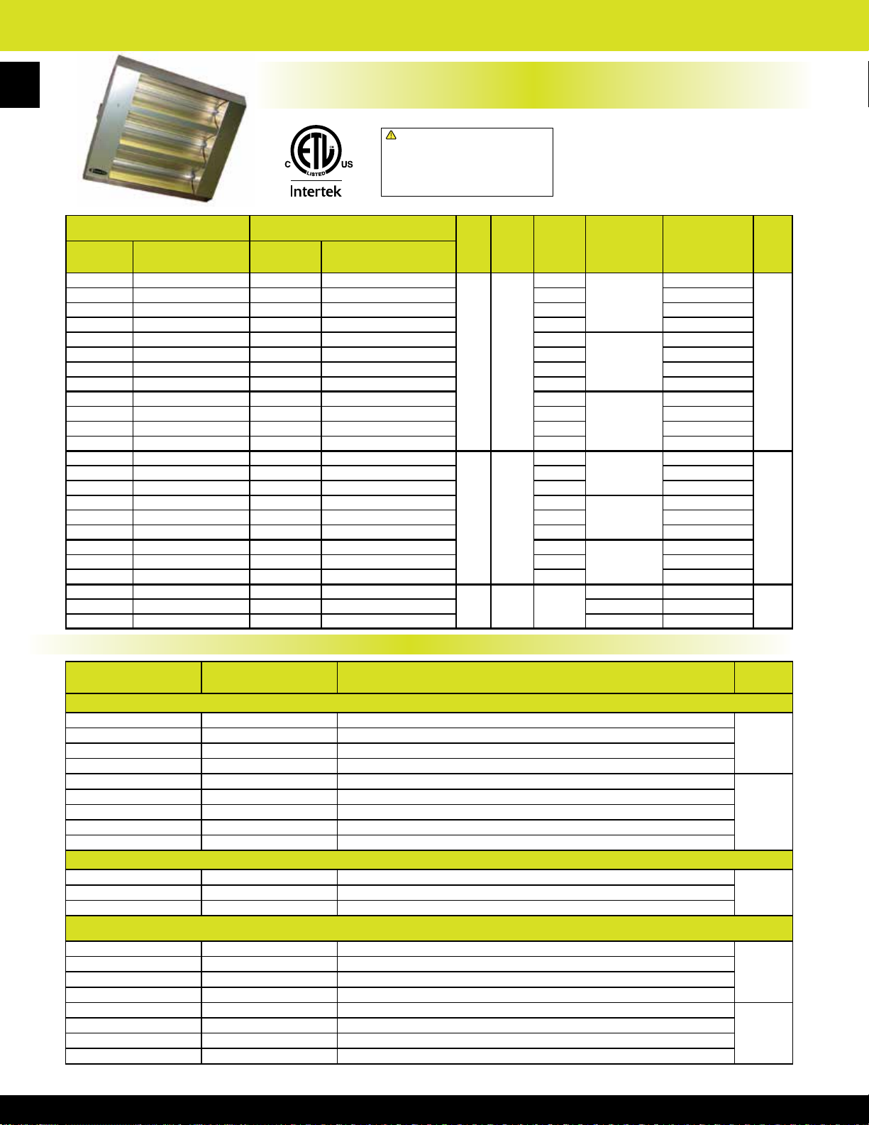
TH & THSS Series Mul-T-Mount Electric Infrared Heater
78
3-Lamp Mul-T-Mount Series - Bankers Bronze Or Stainless Steel Housing
With (3) Clear 8mm Quartz Lamps and Amber Gray Sleeves Included
!
WARNING: This product can expose you
to chemicals including nickel which is known
to the State of California to cause cancer,
and chromium, which is known to the State
of California to cause birth defects and/or
reproductive harm. For more information go
to www.P65Warnings.ca.gov.
BROWN HOUSING STAINLESS STEEL HOUSING
MFG
CATALOG
NUMBER
04908002 223-30-TH-208V-AG 04910402 223-30-THSS-208V-AG
04908102 223-30-TH-240V-AG 04910502 223-30-THSS-240V-AG 240 04912902
04908202 223-30-TH-277V-AG 04910602 223-30-THSS-277V-AG 277 04913002
04908302 223-30-TH-480V-AG 04910702 223-30-THSS-480V-AG 480 04913102
04908402 223-60-TH-208V-AG 04910802 223-60-THSS-208V-AG 208
04908502 223-60-TH-240V-AG 04910902 223-60-THSS-240V-AG 240 04912902
04908602 223-60-TH-277V-AG 04911002 223-60-THSS-277V-AG 277 04913002
04908702 223-60-TH-480V-AG 04911102 223-60-THSS-480V-AG 480 04913102
04908802 223-90-TH-208V-AG 04911202 223-90-THSS-208V-AG 208
04908902 223-90-TH-240V-AG 04911302 223-90-THSS-240V-AG 240 04912902
04909002 223-90-TH-277V-AG 04911402 223-90-THSS-277V-AG 277 04913002
04909102 223-90-TH-480V-AG 04911502 223-90-THSS-480V-AG 480 04913102
04909202 343-30-TH-208V-AG 04911602 343-30-THSS-208V-AG
04909302 343-30-TH-240V-AG 04911702 343-30-THSS-240V-AG 240 04913302
04909402 343-30-TH-480V-AG 04911802 343-30-THSS-480V-AG 480 04913502
04909502 343-60-TH-208V-AG 04911902 343-60-THSS-208V-AG 208
04909602 343-60-TH-240V-AG 04912002 343-60-THSS-240V-AG 240 04913302
04909702 343-60-TH-480V-AG 04912102 343-60-THSS-480V-AG 480 04913502
04909802 343-90-TH-208V-AG 04912202 343-90-THSS-208V-AG 208
04909902 343-90-TH-240V-AG 04912302 343-90-THSS-240V-AG 240 04913302
04910002 343-90-TH-480V-AG 04912402 343-90-THSS-480V-AG 480 04913502
04910102 463-30-TH-480V-AG 04912502 463-30-THSS-480V-AG
04910202 463-60-TH-480V-AG 04912602 463-60-THSS-480V-AG 60° Sym. 04913602
04910302 463-90-TH-480V-AG 04912702 463-90-THSS-480V-AG 90° Sym. 04913602
MFG
MODEL
NUMBER
MFG
CATALOG
NUMBER
MFG
MODEL
NUMBER
KW BTUs VOLTS
4.8 16,382
7.5 25,298
10.95 37,372 480
• Heaters shipped with glare reducing
sleeves & elements
• Asymmetrical pattern units are also
available for 30° & 60°
• Made in U.S.A.
8mm DIAMETER
REPLACEMENT
LAMP
04912802
04912802
04912802
04913202
04913202
04913202
208
208
REFLECTOR
PATTERN
30° Symmetrical
60° Symmetrical
90° Symmetrical
30° Symmetrical
60° Symmetrical
90° Symmetrical
30° Sym. 04913602
WT.
(LBS)
25
33
41
TH & THSS Series Replacement Lamps & Sleeves
MFG CATALOG
NUMBER
04912802 59129101 8mm 1600W, 208V LAMP
04912902 59129102 8mm 1600W, 240V LAMP
04913002 59129103 8mm 1600W, 277V LAMP
04913102 59129104 8mm 1600W, 480V LAMP
04913202 59129105 8mm 2500W, 208V LAMP
04913302 59129106 8mm 2500W, 240V LAMP
04913402 59129107 8mm 2500W, 277V LAMP
04913502 59129108 8mm 2500W, 480V LAMP
04913602 59129109 8mm 3650W, 480V LAMP
04891102 59111102 AMBER GRAY SLEEVE FOR 1600 WATT MODELS
04891302 59111106 AMBER GRAY SLEEVE FOR 3650 WATT MODELS
04899202 AGS1620 1600 W 208 V 8mm AMBER GRAY SLEEVE / LAMP KIT
04899302 AGS1624 1600 W 240 V 8mm AMBER GRAY SLEEVE / LAMP KIT
04899402 AGS1627 1600 W 277 V 8mm AMBER GRAY SLEEVE / LAMP KIT
04899502 AGS1648 1600 W 480 V 8mm AMBER GRAY SLEEVE / LAMP KIT
04899602 AGS2520 2500 W 208 V 8mm AMBER GRAY SLEEVE / LAMP KIT
04899702 AGS2524 2500 W 240 V 8mm AMBER GRAY SLEEVE / LAMP KIT
04899802 AGS2548 2500 W 480 V 8mm AMBER GRAY SLEEVE / LAMP KIT
04899902 AGS3648 3650 W 480 V 8mm AMBER GRAY SLEEVE / LAMP KIT
*2 Lamp xtures require 2 kits; 3 Lamp xtures require 3 kits
600 Volt models not available
MFG MODEL
NUMBER
OPTIONAL 8MM AMBER GRAY SLEEVE / LAMP KIT*
(kits can be used as replacements for any existing Mul-T-Mount xture)
DESCRIPTION WT.(LBS)
8MM REPLACEMENT LAMPS
3
5
AMBER GRAY SLEEVE ONLY
204891202 59111103 AMBER GRAY SLEEVE FOR 2500 WATT MODELS
5
8
Page 80

THA Series Architectural Mul-T-Mount Electric Infrared Heater
3-Lamp Mul-T-Mount Series - Nickel Gray Housing With
(3) Clear 8mm Quartz Lamps and Amber Gray Sleeves Included
• ETL C/US listed for suspended, totally exposed outdoor and
indoor spot comfort heating applications, including exterior
snow/ice control applications
• Clear quartz lamp heating elements, offered in both 2-lamp
and 3-lamp heaters that operate on 208, 240, or 480 volt
• Gold anodized one-piece reector offered in 30°, 60°, or 90°
symmetrical patterns for various distribution of infrared heat
• 6063 extruded aluminum housing, with a painted powder
Heavy Duty Extruded
Aluminum Housing
Glare Reduction Element & Sleeve
Combination Heater Series
!
WARNING: This product can expose you
to chemicals including nickel which is known
to the State of California to cause cancer,
and chromium, which is known to the State
of California to cause birth defects and/or
reproductive harm. For more information go
to www.P65Warnings.ca.gov.
NICKEL GRAY HOUSING
MFG
CATALOG
NUMBER
04896202 223-30-THA-208V
04896302 223-30-THA-240V 240 04912902
04896402 223-30-THA-277V 277 04913002
04896502 223-30-THA-480V 480 04913102
04896602 223-60-THA-208V 208
04896702 223-60-THA-240V 240 04912902
04896802 223-60-THA-277V 277 04913002
04896902 223-60-THA-480V 480 04913102
04897002 223-90-THA-208V 208
04897102 223-90-THA-240V 240 04912902
04897202 223-90-THA-277V 277 04913002
04897302 223-90-THA-480V 480 04913102
04897402 343-30-THA-208V
04897502 343-30-THA-240V 240 04913302
04897602 343-30-THA-480V 480
04897702 343-60-THA-208V 208
04897802 343-60-THA-240V 240 04913302
04897902 343-60-THA-480V 480
04898002 343-90-THA-208V 208
04898102 343-90-THA-240V 240 04913302
04898202 343-90-THA-480V 480
04898302 463-30-THA-480V
04898402 463-60-THA-480V 10.95 60° Symmetrical 04913602
04898502 463-90-THA-480V 90° Symmetrical 04913602
NOTE:
• All THA models have the same housing dimensions and require the same mounting clearances as the TH/THSS models; see page 73
• See page 74 for sizing chart information
• Asymmetrical pattern units are also available for 30° & 60°, contact factory for more information
MFG
MODEL
NUMBER
coated nickel gray nish
• Housing is extremely durable and attractively designed for
commercial applications
• All 3-lamp heaters wire for either single or three-phase wiring.
• 2-lamp heaters wire for single-phase operation
• Includes surface mounting brackets & glare reducing sleeves
to eliminate 94% of the quartz lamp lumen output
• Made in the USA
KW BTUs VOLTS
208
4.8 16382
208
7.5 25298
37372 480
REFLECTOR
PATTERN
30° Symmetrical
60° Symmetrical
90° Symmetrical
30° Symmetrical
60° Symmetrical
90° Symmetrical
30° Symmetrical 04913602
8mm DIAMETER
REPLACEMENT
LAMP
04912802
04912802
04912802
04913202
04913502
04913202
04913502
04913202
04913502
WT. (LBS)
79
25
33
41
Page 81

THA Series Architectural Mul-T-Mount Electric Infrared Heater
80
(2) Clear 8mm Quartz Lamps and Amber Gray Sleeves Included
NICKEL GRAY HOUSING
MFG
CATALOG
NUMBER
04892202 222-30-THA-208V
04892302 222-30-THA-240V 240 04912902
04892402 222-30-THA-277V 277 04913002
04892502 222-30-THA-480V 480 04913102
04892602 222-A30-THA-208V 208
04892702 222-A30-THA-240V 240 04912902
04892802 222-A30-THA-277V 277 04913002
04892902 222-A30-THA-480V 480 04913102
04893002 222-60-THA-208V 208
04893102 222-60-THA-240V 240 04912902
04893202 222-60-THA-277V 277 04913002
04893302 222-60-THA-480V 480 04913102
04893402 222-A60-THA-208V 208
04893502 222-A60-THA-240V 240 04912902
04893602 222-A60-THA-277V 277 04913002
04893702 222-A60-THA-480V 480 04913102
04893802 222-90-THA-208V 208
04893902 222-90-THA-240V 240 04912902
04894002 222-90-THA-277V 277 04913002
04894102 222-90-THA-480V 480 04913102
04894202 342-30-THA-208V
04894302 342-30-THA-240V 240 04913302
04894402 342-30-THA-480V 480 04913502
04894502 342-A30-THA-208V 208
04894602 342-A30-THA-240V 240 04913302
04894702 342-A30-THA-480V 480 04913502
04894802 342-60-THA-208V 208
04894902 342-60-THA-240V 240 04913302
04895002 342-60-THA-480V 480 04913502
04895102 342-A60-THA-208V 208
04895202 342-A60-THA-240V 240 04913302
04895302 342-A60-THA-480V 480 04913502
04895402 342-90-THA-208V 208
04895502 342-90-THA-240V 240 04913302
04895602 342-90-THA-480V 480
04895702 462-30-THA-480V
04895802 462-A30-THA-480V 30° Asymmetrical 04913602
04895902 462-60-THA-480V 7.3 60° Symmetrical 04913602
04896002 462-A60-THA-480V 60° Asymmetrical 04913602
04896102 462-90-THA-480V 90° Symmetrical 04913602
MFG
MODEL
NUMBER
2-Lamp Mul-T-Mount Series Nickel Gray With
KW BTUs VOLTS REFLECTOR PATTERN
208
30° Symmetrical
30° Asymmetrical
3.2 10,922
208
5.0 17,065
24,915 480
60° Symmetrical
60° Asymmetrical
90° Symmetrical
30° Symmetrical
30° Asymmetrical
60° Symmetrical
60° Asymmetrical
90° Symmetrical
30° Symmetrical
8mm DIAMETER
REPLACEMENT
LAMP
04912802
04912802
04912802
04912802
04912802
04913202
04913202
04913202
04913202
04913202
04913502
04913602
NOTE: Consult the factory, the product instruction manual, or a licensed electrician for 3-phase wiring of all 2-element heaters.
WT. (LBS)
20
25
32
Optional THA Wire Guards
MFG CATALOG NUMBER MFG MODEL NUMBER
04898602 THA222 GUARD
04898702 THA223 GUARD
04898802 THA342 GUARD
04898902 THA343 GUARD
04899002 THA462 GUARD
04899102 THA463 GUARD
Page 82

OCH Series Outdoor / Indoor Rated Quartz Electric Infrared Heater
Features
• Frosted Quartz Tube heating element (included)
• Listed for suspended, totally exposed (outdoor) and indoor spot
Heats solid objects, not the air!
!
WARNING: This product can expose you
to chemicals including nickel which is known
to the State of California to cause cancer,
and chromium, which is known to the State
of California to cause birth defects and/or
reproductive harm. For more information go
to www.P65Warnings.ca.gov.
FINISH - BROWN FINISH - STAINLESS Steel
heating applications
• Finish: High-temp brown powder coated nish or corrosion resistant
stainless steel 24 gauge housing
• 60° Symmetric Heat Pattern
• Gold anodized Aluminum reector and end caps
• Painted models are direct wire, unless specied and are supplied with
6” lead wires for eld connection in the internal wiring compartment.
These models are available with a factory installed 6’ cord set. The
208V model must have a eld supplied plug.
• Stainless steel models include an electrical enclosure assembled to
the end of the heater housing and (2) 6” long lead wires for direct
eld connection.
• Two 2’ ft. long mounting chains and four S-Hooks included
• The OCH-Series can be surfaced mounted using the supplied
mounting brackets which allow up to a 45° horizontal tilt adjustment.
• Made in U.S.A.
Product Models
81
Includes Electrical Enclosure
MFG
CATALOG
NUMBER
04804402 OCH-46-120VE 04805202 OCH-46-120V-SSE
04804502 OCH-46-208VE 04805302 OCH-46-208V-SSE 2000 6826 208 9.6 671-5061
04804602 OCH-46-240VE 04805402 OCH-46-240V-SSE 2000 6826 240 8.3 671-3785
04804702 OCH-46-277VE 04805502 OCH-46-277V-SSE 2000 6826 277 7.2 671-5018
04804902 OCH-57-208VE 04805702 OCH-57-208V-SSE 3000 10239 208 14.4 671-5060
04804802 OCH-57-240VE 04805602 OCH-57-240V-SSE 3000 10239 240 12.5 671-3786
04805002 OCH-57-277VE 04805802 OCH-57-277V-SSE 3000 10239 277 10.8 671-5059
04805102 OCH-57-480VE 04805902 OCH-57-480V-SSE 2250 7679 480 4.7 671-5058
04859702 OCH-46-120VCE --- ---
04859802 OCH-57-208VCE --- --- 3000 10239 208 14.4 671-5061
04859902 OCH-57-240VCE --- --- 3000 10239 240 12.5 671-3786
MFG
MODEL
NUMBER
MFG
CATALOG
NUMBER
MFG
MODEL
NUMBER
CONNECTION
TYPE
Hard Wire
Corded
WATTS BTUs VOLTS AMPS
1500 5120 120 12.5 671-3784
1500 5120 120 12.5 671-3784 11
Qtz. Tube
Repl.
Element
Product Accessories
WT.
(LBS)
10
12
13
MFG
CATALOG
NUMBER
04808802 OCHWG-46
04808902 OCHWG-57 OCH-57 Series Models 2
08811239 VMB-41-SS Wall Mtg. Brackets (2) ALL OCH Models 12
04459402 VHC-15 Variable Heat Controller 208/240V OCH Models Only 3
04853502 VHC-32 Variable Heat Controller 208/240V OCH Models Only 3
MFG
MODEL
NUMBER
DESCRIPTION FOR USE WITH
OCH-46 Series Models 2
Stainless Steel Wire Guards
WT.
(LBS)
Page 83

OCH Series Outdoor / Indoor Rated Quartz Electric Infrared Heater
82
OCH / OCH2 Sizing Chart
MOUNTING HEIGHT HEATER MFG MODEL WATTS
7’ OCH-46
OCH-46
8’
9’
10’
12’
14’
OCH-57
OCH2-55 4000 16 10 160 25.0
OCH2-66 6000 17 10 170 35.3
OCH-46
OCH-57
OCH-57
OCH2-55 4000 19 13 247 16.2
OCH2-66 6000 20 13 260 23.0
OCH-57
OCH2-55 4000 22 15 330 12.1
OCH2-66 6000 23 15 345 17.4
OCH2-55 4000 25 17 425 9.4
OCH2-66 6000 26 17 442 13.6
1500 11 9 99 15.2
2000 11 9 99 20.2
1500 12 10 120 12.5
2000 12 10 120 16.7
3000 13 10 130 23.1
2250 13 10 130 17.3
1500 13 11 143 10.5
2000 13 11 143 14.0
3000 14 11 154 19.5
2250 14 11 154 14.6
3000 15 12 180 16.7
2250 15 12 180 12.5
3000 17 14 238 12.6
2250 17 14 238 9.5
HEAT PATTERN COVERAGE (AT FLOOR LEVEL)
LENGTH WIDTH SQ. FT.
TOTAL WATTS /
SQ. FT.
Product Specications
Series: Dimensions:
OCH-46 Length: 48”; Width: 5.375”; Height: 6.5”
OCH-57 Length: 59”; Width: 5.375”; Height: 6.5”
Housing:
24gaugeAluminizedSteelwithabakedonbrownpowdercoatfinish.HousingiscETLusListedforindoororoutdoorapplications.
Horizontal mounting only.
Reflectors and End Caps:
.040GoldanodizedAluminumreflectorsandendcapsforsuperiorreflectiveness.60degreemedium(symmetric)patternonly.
Elements:
QuartzTubes.FrostedquartzenvelopewithaNickel-Chromiumcoiledfilament,porcelainendcaps,andthreaded-screw(stud)
terminations.Fastheat-up and cool-down performance. Available Wattagesfrom1500to3000 Wattsperelement.Available
voltages from 120 to 480 Volts.
Controls:
OCHSeriesheatersarenotmanufacturedwithanycontroldeviceontheunit.Allcontrolsareaccessoriesandshouldbespecified
as such. Please consult the technical salesdepartment of factory for helpin determining applicable controls. Please follow
installationinstructionsthataccompanyeachheater.
Accessories:
Adjustablemountingbrackets(stainlesssteel only), vertical mounting brackets (stainless steelonly),wireguards,thermostats,
SCRcontrollers,andpowercontactorpanels.
Mounting Congurations & Reector Pattern
Mounting
• Chain, surface mount or use our vertical mounting bracket as shown below. Note: All units must be mounted horizontally.
• In-Builtsurfacemountingbracketallowsforxtureadjustmentuptoa45°horizontaltilt.
• Asshown,theheatermaybesuspendedatanyhorizontalangledesired.
Chain Mount:
(Chain supplied)
Optional Vertical Mounting Bracket:
Model # VMB-41-SS
Mounting Clearances & Recommended Mounting Height
MOUNTING CLEARANCES RECOMMENDED MOUNTING HEIGHT
3” from ceiling; 12” from vertical surface
72” from face of heater to combustible surface
36” from another heater
Reector Pattern:
60°
OCH-46 7’-9’
OCH-57 8’-10’
Page 84

OCH2 Series Outdoor / Indoor Rated Quartz Electric Infrared Heater
NEW PRODUCT
for 2020
• 2 Frosted Quartz Tube heating elements (included)
Features
• Listed for suspended, totally exposed (outdoor) and
indoor** spot heating applications
• Finish: High-temp brown powder coated nish or
corrosion resistant stainless steel 20 gauge housing
• 60° Symmetric Heat Pattern
Heats solid objects, not the air!
• GoldanodizedAluminumreectorandendcaps
• 6”longleadwiresfordirecteldconnection
• Two 2’ ft. long mounting chains and four
S-Hooks included
• The OCH2-Series can be wall or ceiling mounted using
the supplied mounting brackets which allow up to a 45°
horizontal tilt adjustment
• Made in U.S.A.
Series: Dimensions:
OCH2-55 Length: 55”; Width: 7.5”; Height: 7”
OCH2-66 Length: 66”; Width: 7.5”; Height: 7”
Product Models
MFG
CATALOG
NUMBER
PAINTED BROWN
MFG MODEL NUMBER MFG MODEL NUMBER
04915502 OCH2-55-208V 04915902 OCH2-55-208V-SS
04915602 OCH2-55-240V 04916002 OCH2-55-240V-SS 240 16.67 671-5063
04915702 OCH2-55-277V 04916102 OCH2-55-277V-SS 277 14.44 671-5064
04915802 *OCH2-55-480V 04916202 *OCH2-55-480V-SS 480 8.33 *671-5063
04916302 OCH2-66-208V 04916702 OCH2-66-208V-SS
04916402 OCH2-66-240V 04916802 OCH2-66-240V-SS 240 25 671-5066
04916502 OCH2-66-277V 04916902 OCH2-66-277V-SS 277 21.66 671-5067
04916602 *OCH2-66-480V 04917002 *OCH2-66-480V-SS 480 12.5 *671-5066
*480V models use (2) 240V elements wired in series. **Not for residential use
MFG
CATALOG
NUMBER
STAINLESS STEEL
WATTS BTUs VOLTS AMPS
208 19.23 671-5062
4000 13652
208 28.85 671-5065
6000 20478
Qtz. Tube Repl.
Element
83
Product Accessories
MFG
CATALOG
NUMBER
04917102 OCH2WG-55
04917202 OCH2WG-66 OCH2-66 Series Models
MFG
MODEL
NUMBER
DESCRIPTION FOR USE WITH
Wire Guards
OCH2-55 Series Models
Mounting Congurations & Reector Pattern
Mounting
• Chain, surface mount or use our vertical mounting bracket as shown below. Note: All units must be mounted horizontally.
• In-Builtsurfacemountingbracketallowsforxtureadjustmentuptoa45°horizontaltilt.
• As shown, the heater may be suspended at any horizontal angle desired.
30"
INCHES
MIN.
CEILING
Chain Mount:
(Chain supplied)
Reector Pattern:
INCHES
6
MIN.
85" INCHES MIN.
3
"
4
Optional Vertical Mounting Bracket:
Model # VMB-41-SS
60°
FLOOR
Mounting Clearances & Recommended Mounting Height
MOUNTING CLEARANCES RECOMMENDED MOUNTING HEIGHT
6-3/4” from ceiling; 30” from vertical surface
85” from face of heater to combustible surface
36” from another heater
OCH2-55 9’-11’
OCH2-66 10’-12’
W
A
L
L
3
"
6
4
INCHES
MIN.
INCHES
3
"
6
MIN.
4
82" INCHES MIN.
Page 85

84
RPH Series Outdoor Rated Stainless Steel Electric Infrared Heater
• Instant, high-intensity radiant heat, with 30° symmetric heat pattern
• Listed for indoor spot heating and for outdoor unprotected applications
• Specialized Ruby “Red” Quartz Lamp infrared heating element for glare reduction
• Stainless Steel housing with Coilzak Aluminum reector for good reectivity & corrosion
!
WARNING: This product can expose you
to chemicals including nickel which is known
to the State of California to cause cancer,
and chromium, which is known to the State
of California to cause birth defects and/or
reproductive harm. For more information go
to www.P65Warnings.ca.gov.
OPTIONAL WIREGUARD
WT.
(LBS)
MFG
CATALOG
NUMBER
04466302 RPHWG
Mounting Plate (provided)
on top center allows heater
to be mounted parallel or
angled using a standard
pipe nipple and box cover
(supplied by installer)
resistance
• Heating element and mounting plate included
• Dimensions: 24” x 5
3
⁄8” x 4 1⁄2.”
• Made in U.S.A.
MOUNTING CLEARANCES RECOMMENDED MOUNTING HEIGHT
6” from ceiling
24” from vertical surface
72” from face of heater to combustible surface
MFG
CATALOG
NUMBER
08845039 RPH-208-A 1600 5,461 208 1 7.7 632-1620 5
08845139 RPH-240-A 1600 5,461 240 1 6.7 632-1624 5
MFG
MODEL
NUMBER
WATTS BTUs VOLTS PHASE AMPS
RPH-208 8’-12’
RPH-240 8’-12’
REPLACEMENT
QUARTZ LAMP
MM Series “Mitey Midget” Electric Infrared Heater
• Instant, high-intensity radiant heat, with 60° symmetric heat pattern
• MM heaters excel as people-heaters in areas requiring a linear,
compact & concentrated heat source
• Listed for indoor industrial and commercial comfort heat applications
• Heavy duty Aluminum extrusion with a bright
!
WARNING: This product can expose you
to chemicals including nickel which is known
to the State of California to cause cancer,
and chromium, which is known to the State
of California to cause birth defects and/or
reproductive harm. For more information go
to www.P65Warnings.ca.gov.
MFG
CATALOG
NUMBER
MFG
MODEL
NUMBER
04440102 MM-13A 500 1707 120 1 13" 3 04439002 MMWG-13
04495402 MM-24A 900 / 1600 5461 277 1 24" 5 04418902 MMWG-24
04427202 MM-33A 2500 8533 600 1 33" 6 04439202 MMWG-33
04420302 MM-46A 3000 / 3800 12457 600 1 46" 7 04420402 MMWG-46
Note: All MM-13A through MM-46A models are ETL Listed for use with Quartz Lamps Only!
Lamp voltage must match supply voltage.
Aluminum insert for maximum reectivity
• Anodized Aluminum housing, (0.62” thick)
• Heat Element Sold Separately
• Dimensions: 3.750” Wide x 3.380” High
• Made in U.S.A.
MAX
WATTS
MAX
BTUs
MAX
VOLTS
PH
Mounting Clearances
24” from ceiling & from vertical surface
24” from face of heater to combustible surface
36” from another heater
OPTIONAL WIREGUARDS
UNIT
LENGTH
WT.
(LBS)
MFG
CATALOG
NUMBER
MODEL
NUMBER
MFG
MODEL
NUMBER
MFG
FFH Series Electric Utility Infrared Heater
• Both FFH Series Heaters are excellent for Farrowing & Finishing applications
• Both units feature an 8 ft. 18/3 grounded cordset to plug into any 120V service
• Gold anodized Aluminum reectors, with a 90° symmetrical reector pattern
• Compact housing design, with the following housing nish:
FFH-512A: Gold Anodized Finish
FFH-912B: Brown Enamel Finish
FFH-512A
FFH-912B
!
WARNING: This product can expose you
to chemicals including nickel which is known
to the State of California to cause cancer,
and chromium, which is known to the State
of California to cause birth defects and/or
reproductive harm. For more information go
to www.P65Warnings.ca.gov.
MFG CATALOG
NUMBER
MFG MODEL
NUMBER
08838900 FFH-512A 550 1877 120 1 5 671-3492 4 22 5 3
08827814 FFH-912B 450/900 3072 120 1 8 671-3454 4 17 6 4
• Quartz Tubes Heat Element(s), Wire Guard & (2) 4’ ft. Jack Chains are included
• FFH-912B Only: Offers (2) On/Off toggle switches to operate heating elements independently
• Listed for indoor industrial and
commercial comfort heat
• Made in U.S.A.
MOUNTING CLEARANCES
3” from ceiling
24” from vertical surface
72” from oor
WATTS BTUs VOLTS PHASE AMPS
MOUNTING
HEIGHT
6’
7’
8’
REPLACEMENT
QUARTZ TUBE
SIZING CHART - FFH SERIES
HEATER
MODEL
FFH-512A 7 6 42 13.1
FFH-912B 6 7 42 21.4
FFH-512A 8 7 56 9.8
FFH-912B 7 8 56 16.1
FFH-512A 9 8 72 7.6
FFH-912B 8 9 72 12.5
LENGTH WIDTH
WT.
(LBS)
Length Width Height
COVERAGE
(Sq. Ft.)
Dimensions (in.)
WATTS
/ Sq. Ft.
Page 86

Electric Infrared Heating Elements
Clear & Red Quartz Lamps - 12mm Diameter
• Near wavelength infrared, color temp. emitted
approx. 4100° F (high brightness)
•Approximately96%radiantefciency
• Excellent resistance to thermal shock
• Highest moisture resistance and quickest heat-up
time
3
⁄8” Diameter clear or red quartz envelope
•
•Coiledtungstenlament;sealedporcelainendcaps;
halogengaslled
Modelprextypes:
630 = Horizontal Burning “Clear”
631 = Vertical OR Horizontal Burning
“Clear”
632 = Horizontal Burning “Red”
Notes:
Life expectancy of all heating elements - 5,000 hours
All heating elements operate at 50 / 60 Hertz.
!
WARNING: This product can expose you
to chemicals including nickel which is known
to the State of California to cause cancer,
and chromium, which is known to the State
of California to cause birth defects and/or
reproductive harm. For more information go
to www.P65Warnings.ca.gov.
• Medium wavelength infrared, color temp
emitting approx. 1800°F (bright orange glow)
•Approximately60%radiantefciency
• Nickel-Chromium alloy coiled element
with porcelain end caps and pigtailed
termination
5
⁄8” Diameter frosted quartz envelope
•
• Fast heat-up/cool-down
Notes:
Life expectancy of all heating elements - 5,000 hours
All heating elements operate at 50 / 60 Hertz.
!
WARNING: This product can expose you
to chemicals including nickel which is known
to the State of California to cause cancer,
and chromium, which is known to the State
of California to cause birth defects and/or
reproductive harm. For more information go
to www.P65Warnings.ca.gov.
Flat Panel Emitter Replacement Complete Conversion Kits - MR, CH, & FHK
MFG CATALOG
NUMBER
01358102 64337-022
01358202 64337-023 240 MR-424-1, CH-424-1C, CH-424-1A
01358302 64337-024 277 MR-427-1, CH-427-1C, CH-427-1A
01358402 64337-025 480 MR-448-1, CH-448-1C, CH-448-1A
01358502 64337-026 600 MR-457-1, CH-457-1C, CH-457-1A
01358602 64337-027
01358702 64337-028 240 MR-624-3, CH-624-3C, CH-624-3A
01358802 64337-029 277 MR-627-3, CH-627-3C, CH-627-3A
!
WARNING: This product can expose you
to chemicals including nickel which is known
to the State of California to cause cancer,
and chromium, which is known to the State
of California to cause birth defects and/or
reproductive harm. For more information go
to www.P65Warnings.ca.gov.
01358902 64337-030 480 MR-648-3, CH-648-3C, CH-648-3A
01359002 64337-031 600 MR-657-3, CH-657-3C, CH-657-3A
01359102 64337-032
01359202 64337-033 240 MR-1324-3, CH-1324-3B, CH-1324-3A
01359302 64337-034 277 MR-1327-3, CH-1327-3B, CH-1327-3A
01359402 64337-035 480 MR-1348-3, CH-1348-3B, CH-1348-3A
01359502 64337-036 600 MR-1357-3, CH-1357-3B, CH-1357-3A
01359602 64337-037
01359702 64337-038 240 MR-2724-3, CH-2724-3C, CH-2724-3B
01359802 64337-039 277 MR-2727-3, CH-2724-3C, CH-2724-3B
01359902 64337-040 480 MR-2748-3, CH-2748-3C, CH-2748-3B
01360002 64337-041 600 MR-2757-3, CH-2757-3C, CH-2757-3B
01360802 64337-049
01360902 64337-050 240 FHK-624-3A
01361002 64337-051 480 FHK-648-3A
01361102 64337-052
01361202 64337-053 240 FHK-1324-3A
01361302 64337-054 480 FHK-1348-3A
Note: There are no element replacement kits for CH-2, MR-2, FHK-2, or FHK-4 model series heaters.
MFG
CATALOG
NUMBER
MFG
MODEL
NUMBER
WATTS VOLTS
04400502 630-05129 500 120 8
04401602 630-16209
208
LENGTH (IN.)
Overall Heated
11
04401702 630-16249 240
04409902 631-16249 240
1600
19
04401802 630-16279 277
04817302 630-16489 480
04817402 630-25209
208
04817502 630-25249 240
04817602 630-25279 277
04405402 630-25489 480
2500
28
04403602 631-25489 480
04406802 631-25609 600
04406702 630-36489 3650 480
04462302 630-38579
04441302 631-38579 600
04461502 632-1620
04461602 632-1624 240
3800
1600
600
208
41
19
04462202 632-2548 2500 480 28
Quartz Tubes
MFG
CATALOG
NUMBER
04432302 671-3784 1500 120
04418102 671-5061 2000 208
04418002 671-3785 2000 240
04419302 671-5018 2000 277
04416602 671-5060 3000 208
04414702 671-3786 3000 240
04419402 671-5059 3000 277
04419502 671-5058 2250 480
04914702 671-5062
04914902 671-5064 277
04915002 671-5065
04915202 671-5067 277
04403502 671-3454 450 120 12
04400802 671-3492* 550 120 19
04462402 671-5056 1000 120 18
04462502 671-5057 1425 240 27
*3⁄8” Diameter
CH & MR SERIES - FLAT PANEL EMITTER CONVERSION KITS
MFG MODEL
MFG
MODEL
WATTS VOLTS
NUMBER
208
4000
208
6000
NUMBER
WATTS VOLTS FOR USE WITH OLD MODEL #:
208 MR-420-1, CH-420-1C, CH-420-3A
3150
208 MR-620-3, CH-620-3C, CH-620-3A
4300
208 MR-1320-3, CH-1320-3B, CH-1320-3A
9500
208 MR-2720-3, CH-2720-3C, CH-2720-3B
9500
FHK Series - Flat Panel Emitter Conversion Kits
208 FHK-620-3A
4300
208 FHK-1320-3A
9500
⁄16 5
11
⁄16 16
ENVELOPE
TYPE
FITS
MODEL
MM-13A
222, 223,
or MM-24A
12mm
DIAMETER
11
⁄16 25
11
⁄16 38
11
⁄16 16
11
⁄16 25 342 or 343
CLEAR
12mm
DIAMETER
RED
LENGTH (IN.)
Overall Heated
11
39
⁄16 34 3⁄16 OCH-46
11
⁄16 45 3⁄16 OCH-57
50
3
⁄8 43 OCH2-5504914802 671-5063 240
48
1
⁄4 53 3⁄8 OCH2-6604915102 671-5066 240
59
15
⁄16 8 7⁄16 FFH-912B
1
⁄2 16 FFH-512A
5
⁄16 14 7⁄16 CH-2212-1C
5
⁄16 23 7⁄16 CH-6424-1C
342, 343,
or MM-33A
462, 463,
or MM-46A
222/223
or RPH
FITS
MODEL
85
Page 87

Electric Infrared Heating Controls
86
VHC-32
• Solid State phase angle variable “Triac”
knob controller adjusts heat settings
from 10-100% with heat loads up to
15.4-Amps
• 208/240 VAC single-phase, single stage
controller, 3200 Watt max
• Positive “Off” & built-in On/
Off Rocker switch lights “red”
during operation
• NEMA 1 Aluminum enclosure with
stainless steel face plate designed
for wall mounting or suitable for
semi-recessed applications
• Must be mounted in a protected area.
• Can either operate Quartz Lamps or
Quartz Tube Infrared Heaters
!
WARNING: This product can expose you
to chemicals including nickel which is known
to the State of California to cause cancer,
and chromium, which is known to the State
of California to cause birth defects and/or
reproductive harm. For more information go
to www.P65Warnings.ca.gov.
Variable Controllers
30-Amp or 80-Amp Enclosed
VHC-15
• Solid state variable device controls heat
loads up to 15-Amps
• 120/208/240Volt “In-Line” Controller
• Built in On/Off knob switch with positive
“off” & surface plate included
• Designed for a 2” x 4” electrical wall box
mounting (not supplied)
• Must be mounted in a protected area.
• Can only operate Fostoria Quartz Tube
Infrared Heaters
MFG
CATALOG
NUMBER
04853502 VHC-32
04459402 VHC-15
04459502 FTC-30 208/240-Volt; 28 Amp 2 5 5 3
04456302
04456402
04456502
MFG
MODEL
NUMBER
18D-2-30CF
(Open)
18D-2-30CF
(Enclosed)
18D-2-80CF
(Enclosed)
DESCRIPTION
Variable Heat Controller
208/240-Volt; 15.4 Amp
Variable Heat Controller
120/208/240-Volt; 15 Amp
SCR Controller - 26 Amp MAX;
No Enclosure
SCR Controller - 26 Amp MAX;
Enclosure Included
SCR Controller - 80 Amp MAX;
Enclosure Included
• SCR Voltage Controller - 80 Amp MAX.
• Includes (1) 24-volt Potentiometer (3” square) to
control the heat output
• Only operates Quartz Lamps at 240 or 208-Volts,
single phase only
• Potentiometer can be mounted outside, but the
SCR must be located in a protected area
• Factory wired with millisecond fuses included
18D-2-80CF ENC.
DIMENSION (IN.)
Depth Width Height
3 5 5 3
3 5 5 3
6 6 9 11
8 10 12 15
8 12 14 29
WT. (LBS)
Snow & Ice Detectors
• Main control unit for Automatic Snow & Ice Control Systems
• By sensing both temperature and moisture the system activates and
melts any snow & ice accumulations until conditions subside
• NEMA 3R Enclosure is UL Listed and houses timers and switching
electronics to operate the system
• Capability to monitor up to 6 sensors (CIT-1)
CIT-1
!
WARNING: This product can expose you
to chemicals including nickel which is known
to the State of California to cause cancer,
and chromium, which is known to the State
of California to cause birth defects and/or
reproductive harm. For more information go
to www.P65Warnings.ca.gov.
MFG CATALOG
NUMBER
MFG MODEL
NUMBER
APS-3C
DESCRIPTION
03196100 APS-3C Snow / Ice Control Switch 6.56 11.5 9.25 8
03197600 CIT-1 General Purpose Snow Sensor 3.25 3.25 4.13 1
Note: Any snow & ice control system should be used with the correct sized control panel (with contactors & fusing) as supplied by factory or your electrical contractor.
The APS-3C requires a control device (CIT-1) in order to operate properly and must use 120V. Additional controls available through manufacturer.
• Unit can be manually activated and can be controlled and monitored
from an optional remote switch (Model RCU- contact factory)
• Positioned above ground to maximize the sensors capability
• Detects falling or blowing of precipitation such as snow when the
temperature is below 38°F
• Most common sensor device
DIMENSION (IN.)
Depth Width Height
WT.
(LBS)
Contactor Enclosures
FEC-30-120
!
WARNING: This product can expose you
to chemicals including nickel which is known
to the State of California to cause cancer,
and chromium, which is known to the State
of California to cause birth defects and/or
reproductive harm. For more information go
to www.P65Warnings.ca.gov.
MFG CATALOG
NUMBER
MFG MODEL
NUMBER
CONTACTOR
AMPS
04408502 FEC-30-120
04408602 FEC-30-240 208/240
04408702 FEC-60-120
04408802 FEC-60-240 208/240
Note: Installer to provide overload protection for all infrared heaters
• Economical load handling / switch device,
ideal for use with other control equipment
• NEMA 1 Enclosures
• Load rating up to 600V Max., 3-Pole
• Magnetic contactor
CABINET SIZE (IN.)
Depth Width Height
5 6 10 5
30
60
COIL
VOLTAGE
120
120
WT.
(LBS)
Page 88

Electric Infrared Heating Controls - FPC Control Panels
Pre-Wired Contactor Panels
• ONE HEATER PER CIRCUIT
• Max 48-Amps per circuit*
• Step-down transformer for 24V
or 120V control circuit
• Secondary control circuit fusing
• 3-Phase load rated
• NEMA 1 Enclosures
IMPORTANT FUSING INFORMATION
FPC2120
!
WARNING: This product can expose you
to chemicals including nickel which is known
to the State of California to cause cancer,
and chromium, which is known to the State
of California to cause birth defects and/or
reproductive harm. For more information go
to www.P65Warnings.ca.gov.
Fuses are NOT included since panels can be used with various infrared heat sources.
Quartz Lamp Heat Sources: Use FRS-600V (or equal) “Time Delay” fuses; Class RK-5.
Quartz Tube & Flat Panel Emitter Heat Sources: Use KTS-R 600V (or equal)
“Fast Acting” fuses; Class RK-1.
*Circuit fusing less than 35 Amps will require the use of fuse reducers - Not included
Standard Models
120-V CONTROL SYSTEM 24-V CONTROL SYSTEM
MFG
CATALOG
NUMBER
MFG
MODEL
NUMBER
MFG
CATALOG
NUMBER
MFG
MODEL
NUMBER
CIRCUITS VOLTS
87
The following controls are available:
• Snow and Ice Detector (APS-3C)
(120 volt control required)
• Single and Two-Stage Thermostats
(Two-Stage Thermostats require a
minimum of 2 circuits)
CABINET SIZE (IN.)
WT.
(LBS)
DEPTH WIDTH HEIGHT
04459902 FPC8110 04864302 FPC8210
04460002 FPC2110 04864402 FPC2210 240
1
04460102 FPC7110 04864502 FPC7210 277/480
04460202 FPC4110 04864602 FPC4210 480
04460302 FPC8120 04864702 FPC8220
04460402 FPC2120 04864802 FPC2220 240
2
04460502 FPC7120 04864902 FPC7220 277/480
04460602 FPC4120 04865002 FPC4220 480
04460702 FPC8140 04865102 FPC8240
04460802 FPC2140 04865202 FPC2240 240
4
04460902 FPC7140 04865302 FPC7240 277/480
04461002 FPC4140 04865402 FPC4240 480
208
208
208
6.75 16 24 52
6.75 16 24 70
6.75 24 30 88
04461102 FPC8160 04865502 FPC8260
04461202 FPC2160 04865602 FPC2260 240
6
04461302 FPC7160 04865702 FPC7260 277/480
04461402 FPC4160 04865802 FPC4260 480
Note: Products listed in this section are custom built and subject to 100% cancellation/restock charges
208
6.75 30 36 106
Page 89

88
Electric Infrared Heating Controls - ICP Control Panels
GENERAL: ICP panels are built with NEMA rated enclosure and sub panels for mounting electrical controls for use
in staging and control of electric heating products. Panels are designed to comply with local and national codes for in
the eld connections of TPI Corporation heating products.
CONTROLS: Controls for electric heating products shall include, but not be limited to, the following standard controls
for TPI Corporation electric heating products:
• Door interlock disconnect switch for single point eld
power connection
• Circuit breakers sized for AMP load of individual heater rating
• Denite purpose disconnecting contactor for each heater circuit
• Line terminal block for eld connection to heater
• Ground lugs as required by NEC
• Control transformer for control circuit
OPTIONAL CONTROLS:
• Snow and ice melting controllers:
TPI controller - 120V eld connection to controller
Field supplied controllers must specify required voltage
• SCR proportional controllers:
Potentionmeter for manual control of infrared heaters
4-20 MA signal eld supplied for control of infrared heaters
OPTIONAL ACCESSORIES:
• Power on indicator pilot lights
• Staging energized pilot lights
• Pilot switches for manual control per heaters
• Timer for internal control of heater cycle
HOW TO DESIGNATE A MODEL:
ICP- 1 or 3- 1-9- 24 or 120- 120-600- ACCESSORIES- KW-
!
WARNING: This product can expose you
to chemicals including nickel which is known
to the State of California to cause cancer,
and chromium, which is known to the State
of California to cause birth defects and/or
reproductive harm. For more information go
to www.P65Warnings.ca.gov.
Heater Voltage
120, 208, 240,
277, 480, 600
Consult
Factory
KW
Total KW of
the heaters
controlled.
Industrial
Control
Panel
Phase
1 = 1-Phase
3 = 3-Phase
Circuits
1, 2, 3, 4, 5, 6,
7, 8, 9
Control Voltage
24 = 24VAC
120 = 120VAC
TPI Corporation manufactures the ICP panel for control of electric infrared heating products. The models listed
below are standard infrared products and all volts, phase, and amps can be seen in the charts provided on the
pages that correspond to the series.
INFRARED HEATER SERIES HEATER DESCRIPTION
FSS / FSA EMITTER TYPE BLACK BODY HEATER WITH GOLD ANODIZED REFLECTOR
TH / THA QUARTZ LAMP PAINTED STEEL FIXTURE WITH GOLD ANODIZED REFLECTOR
THSS QUARTZ LAMP STAINLESS STEEL FIXTURE WITH GOLD ANODIZED REFLECTOR
OCH / OCH2 OUTDOOR/INDOOR SINGLE LAMP QUARTZ TUBE ELEMENTS
RPH OUTDOOR RATED STAINLESS STEEL SINGLE ELEMENT
Page 90
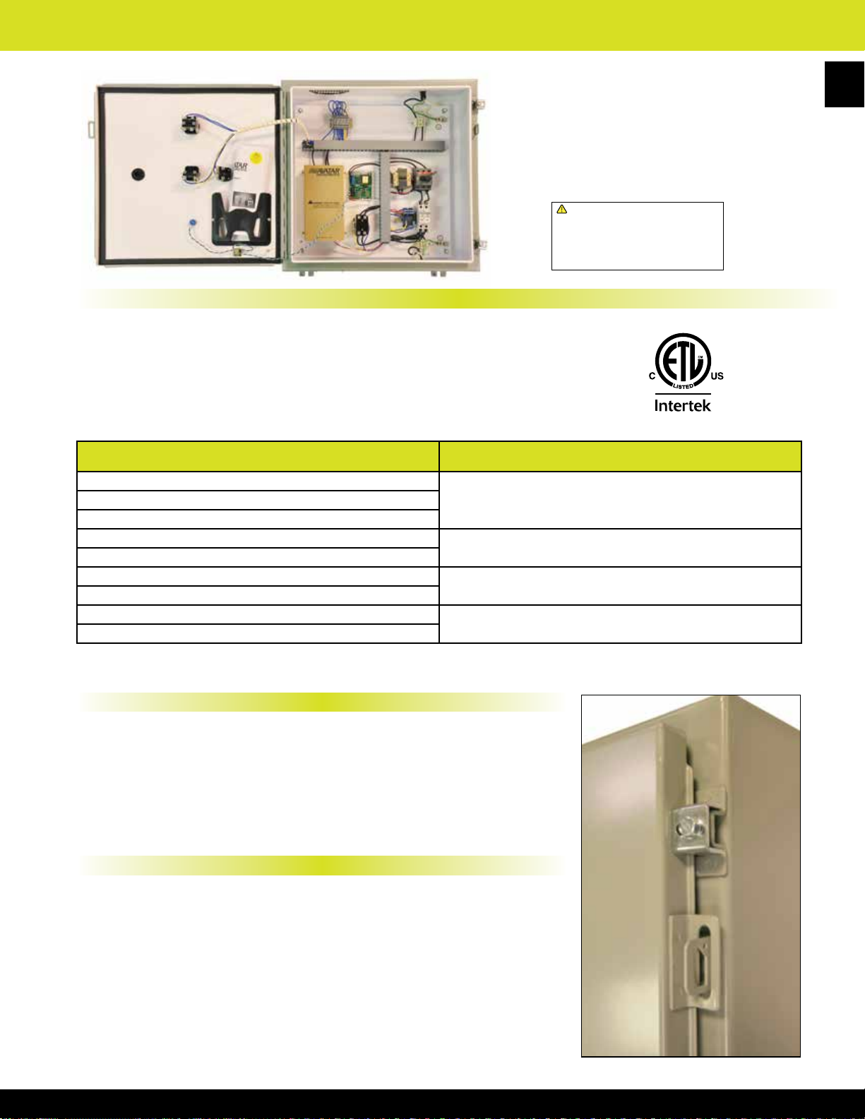
Electric Infrared Heating Controls - ICP Control Panels
Standard Controls
• NEMA 4 outdoor rated industrial gray powder coated
• Door interlock disconnect switch
• Circuit breaker sized for heater load per stage
• Disconnecting magnetic contactor per stage
• Terminal block for eld connection to heater per stage
• 24 Volt transformer (120 Volt transformer optional for snow/ice detectors)
• Control terminal block for connection to staging control
NUMBER OF STAGES PANEL SIZE
1
3
4
5
6
7
8
9
Note: Panel size subject to change depending on options selected
ICP panels are custom made and designed
to be used with any TPI infrared heating
product. Each panel requires an individually
wired circuit for eld connection to the panel
from the heater. ICP panels are designed
and constructed with all controls, factory
wired, and ETL listed.
!
WARNING: This product can expose you
to chemicals including nickel which is known
to the State of California to cause cancer,
and chromium, which is known to the State
of California to cause birth defects and/or
reproductive harm. For more information go
to www.P65Warnings.ca.gov.
24” x 24” x 8”2
30” x 30” x 8”
36” x 36” x 8”
48” x 36” x 8”
89
Snow/Ice Dectection Information
• Snow and ice units activate the system and melts any snow and ice accumulations
until conditions subside based on detection of temperature and moisture.
• 120 Volt control required for use with TPI supplied snow and ice melting options.
This can be indicated by selecting 120 for control voltage option in the model
number designator.
• Snow/Ice control switch: APS-3C (capability of monitoring 6 snow sensors) NEMA
3R Enclosure is UL Listed and houses timers and switching electronics to operate
the system.
Additional Panel Information
• All heater stages are wired to control terminal block individually and can be
controlled individually or grouped together for multiple heaters to be energized by
one thermostat or eld supplied controller as required.
• Infrared heating products can be economically controlled using SCR proportional
controls. Proportional controls can be operated by potentionmeter built into the
control panel with a manual dial or eld wired to building management system using
4-20 MA input to the control panel by control system.
• Timers to allow heater to operate for designed time can be mounted in the control
panel to turn heater off in areas where occupancy is intermittent, such as smoking
areas or public platforms.
• Panel sizes can vary with additional optional controls - consult factory.
Panel Lock-out
Page 91

FSP Series Heavy Duty Flat Panel Emitter Electric Portable Infrared Heater
90
Stand Models Hand Cart Models
FSP-31
FSP-95
FSP-14 FSP-43
!
WARNING: This product can expose you
to chemicals including nickel which is known
to the State of California to cause cancer,
and chromium, which is known to the State
of California to cause birth defects and/or
reproductive harm. For more information go
to www.P65Warnings.ca.gov.
MFG
CATALOG
NUMBER
04883802
04883902
04884002
04884102
04884202
04884302
04884402
04884502
04884602
04884702
04884802
04884902
04885002
04885102
04885202
MFG
MODEL
NUMBER
FSP-3120-1
FSP-3124-1
FSP-3127-1
FSP-3148-1
FSP-3157-1
FSP-4320-3
FSP-4324-3
FSP-4327-1
FSP-4348-3
FSP-4357-3
FSP-9520-3
FSP-9524-3
FSP-9527-1
FSP-9548-3
FSP-9557-3
WATTS VOLTS PHASE
3150 208 1
3150 240 1 13.13 N/A 01360202 64337-043 08804600 SO 14/3
3150 277 1 11.37 N/A 01356802 64337-009 08804600 SO 14/3
3150 480 1 6.56 N/A 01360302 64337-044 08804600 SO 14/3
3150 600 1 6.48 N/A 01357002 64337-011 08804600 SO 14/3
4300 208 1 or 3
4300 240 1 or 3 17.91 10.36 01360402 64337-045 08804900 SO 14/4
4300 277 1 15.52 N/A 01361502 64337-056 08804600 SO 14/3
4300 480 1 or 3 8.96 5.18 01360502 64337-046 08804900 SO 14/4
4300 600 1 or 3 7.48 4.32 01357502 64337-016 08804900 SO 14/4
9500 208 1 or 3
9500 240 1 or 3 39.68 22.89 01360602 64337-047 08805100 S0 8/4*
9500 277 1 34.3 N/A 01361702 64337-058 08805200 SO 8/3
9500 480 1 or 3 19.79 11.44 01360702 64337-048 03164201 SO 12/4
9500 600 1 or 3 16.52 9.54 01362702 64337-063 08804900 SO 14/4
Factory Pre-Wired FSP-14 Model With 15 Ft. Cord with Grounded Plug On/Off Switch
• High density medium wave radiant heat with 60°
• 25,000 hour element life expectancy
• Approximately, 78.5% efcient versus 50% for metal sheath
• Rugged at panel emitter can be used in high vibration
• Single or three phase available on select models
• Heavy duty wire guard mounted on long lasting gold
• Made in U.S.A.
Standard FSP Models
BTUs
/ Hr.
10,749
14,972
32,414
AMPS
1 PH 3 PH
15.4 N/A
20.67 11.94
45.67 26.39
symmetrical heat pattern.
type elements.
areas
anodized reector
Square Feet Heated
NON-PROTECTED
KW
1.45 25 36 40 50 3 feet
3.15 64 75 90 125 3 feet
4.3 85 100 120 150 4 feet
9.5 192 225 270 375 7 feet
WT.
(LBS)
23
32
46
AREA
BELOW ABOVE BELOW ABOVE
o
35
F 35 oF 35 oF 35 oF
FSP Replacement Elements OPTIONAL 25' POWER CORD
MFG
CATALOG
NUMBER
01356602 64337-007 08804600 SO 14/3
01361402 64337-055 03164201 SO 12/4
01361602 64337-057 08805100 S0 8/4*
MODEL
NUMBER
SEMI-PROTECTED
MFG
AREA
MFG
CATALOG
NUMBER
*3 Phase only
Required
Clearance
(from front
of heater)
MFG
MODEL
NUMBER
MFG CATALOG
NUMBER
04883702 FSP-1412-1C STAND 1450 120 1 4947 12.1 17
MFG MODEL
NUMBER
TYPE WATTS VOLTS PHASE BTUs / Hr. AMPS
Infrared Control Options
MFG
CATALOG
NUMBER
04858102 TO-SK-1 Tip-Over Switch 208V - 600V 10.3 10.3 5.0 12
05893702 DC-SK-1 Disconnect Switch 120V - 600V 5.0 6.0 4.0 5
04860202 GF-SK-1
Note: All SK-1 Models have NEMA-1 Enclosure, 50-Amp Max. & 1/3-Phase Rated.
MFG
MODEL
NUMBER
DESCRIPTION
Ground Fault Sensing
Switch
Operating
Voltage (VAC)
208V - 600V 10.3 10.3 5.0 12
Dimensions (In)
Ht. Wd. Dp.
Model “TO” & “GF” features
WT.
include a positive “off” & a
(LBS)
built-in on/off rocker switch that
glows red during operation.
Additionally, enclosure can
mount directly to the terminal
box on the back of the heater
(FSP-43/95 only) or be mounted
to a remote wall surface.
WT.
(LBS)
TO-SK-1
or GF-SK-1
Page 92

PCH Series Portable Quartz Infrared Spot Heater
Width: 53”
Height: 2-6’
Depth: 28”
!
WARNING: This product can expose you
to chemicals including nickel which is known
to the State of California to cause cancer,
and chromium, which is known to the State
of California to cause birth defects and/or
reproductive harm. For more information go
to www.P65Warnings.ca.gov.
Features
• Suitable for portable spot heat or for
curing clear coat paint
• Height adjustable from 2’ to 4’
• On-Off rocker switch standard
• 4 casters included; Tip-Over power
cutoff safety switch
o
• 60
symmetrical heat pattern
5
•
⁄8” diameter quartz tube included
MFG
CATALOG
NUMBER
08841110 PCH-48C 1500 5120 120 1 30
04914502 REPLACEMENT ELEMENT ASSEMBLY
MFG
MODEL
NUMBER
• Average element life is 5000 hours
• Bright Aluminum reector and
end caps
• 20 gauge powder coated Steel housing
• 15’ long, 3 wire (14/3) cordset with
standard 3 pring NEMA 5-20P
• Made in U.S.A.
WATTS BTUs VOLTS PHASE
Portable Infrared Instant On-Off Heat Gun
Features
!
WARNING: This product can expose you
to chemicals including nickel which is known
to the State of California to cause cancer,
and chromium, which is known to the State
of California to cause birth defects and/or
reproductive harm. For more information go
to www.P65Warnings.ca.gov.
• Provides instant spot heat in
a controlled pattern
• Spot cure retouched paint
and other nishes
• De-wrinkle or relax materials
such as cloth-vinyl-leather
91
WT.
(LBS)
• T-3 Tungsten IR lamp
• Ergonomically friendly,
easy-grip handle
• 20’ long, 18/3 grd. cordset
with GFCI plug
• Made in U.S.A.
MFG
CATALOG
NUMBER
05922802 RHG-1012A 1000 120 8.4 3
MFG
MODEL
NUMBER
WATTS VOLTS AMPS
WT.
(LBS)
Portable Electric Infrared Heat Panels
Features
• Portable panels are built to withstand rigors of industrial and heavy-commercial
applications, such as auto collision repair shops
• 20 gauge steel frame, base, and housing construction
• 3” steel casters for high stability and ease of mobility
• Gold anodized Aluminum reectors and end caps allow 10% faster cure time than
polished Aluminum reectors, especially in paint and dust-laden atmospheres
• Elements achieve full temperature in less than 2 minutes
• Fused disconnect switches are installed on the back of each unit
• Units are positioned with adjustable hinges allowing the user to use direct heat
more precisely to the target area
• Gentle but effective medium-wave radiant heat can quickly boost, ash-off, or
cure a variety of nishes, and lessens the chance of blistering and/or overheating
the coating
• Medium-wave infrared heating elements are also effective for ash-off of water-
based clear coatings being mandated by environmental agencies in many states
• Made in U.S.A.
General Curing Guidelines
Material Type
Curing Time 3-5 mins 3-6 mins 8-20 mins 3-10 mins 12-30 mins 10-30 mins
Note: Curing times will vary depending on material and shop conditions. This chart is based on distances of 18-24” away from the target area.
Solvent Based
Primer
Water Based
Primer
Two
Component
Primer
Water Based
Clear Coat
Standard Models
MFG
CATALOG
NUMBER
08841202 HP-5-QT 4,800
08841302 HP-6-QT 6,400 26.7 4
08841402 HP-11-QT 11,200 46.7 7 6-3 SO 89
MFG
MODEL
NUMBER
WATTS VOLTS AMPS
20 4
240
HEAT
SOURCES
CABLE
TYPE (20’)
12-3 SO
HP-5-QT
HP-11-QT
!
WARNING: This product can expose you
to chemicals including nickel which is known
to the State of California to cause cancer,
and chromium, which is known to the State
of California to cause birth defects and/or
reproductive harm. For more information go
to www.P65Warnings.ca.gov.
Acrylic enamel &
Polyurethane Clear Coat
DIMENSION (IN.) HEATED AREA (IN.)
Width Height Width Height
5
44
⁄8
5
66
⁄8 61
56 1⁄2
1
⁄2 77 225
Urethane Clear Coat &
High Solids Top Coat
40
44
WT.
(LBS)
116
141
Page 93
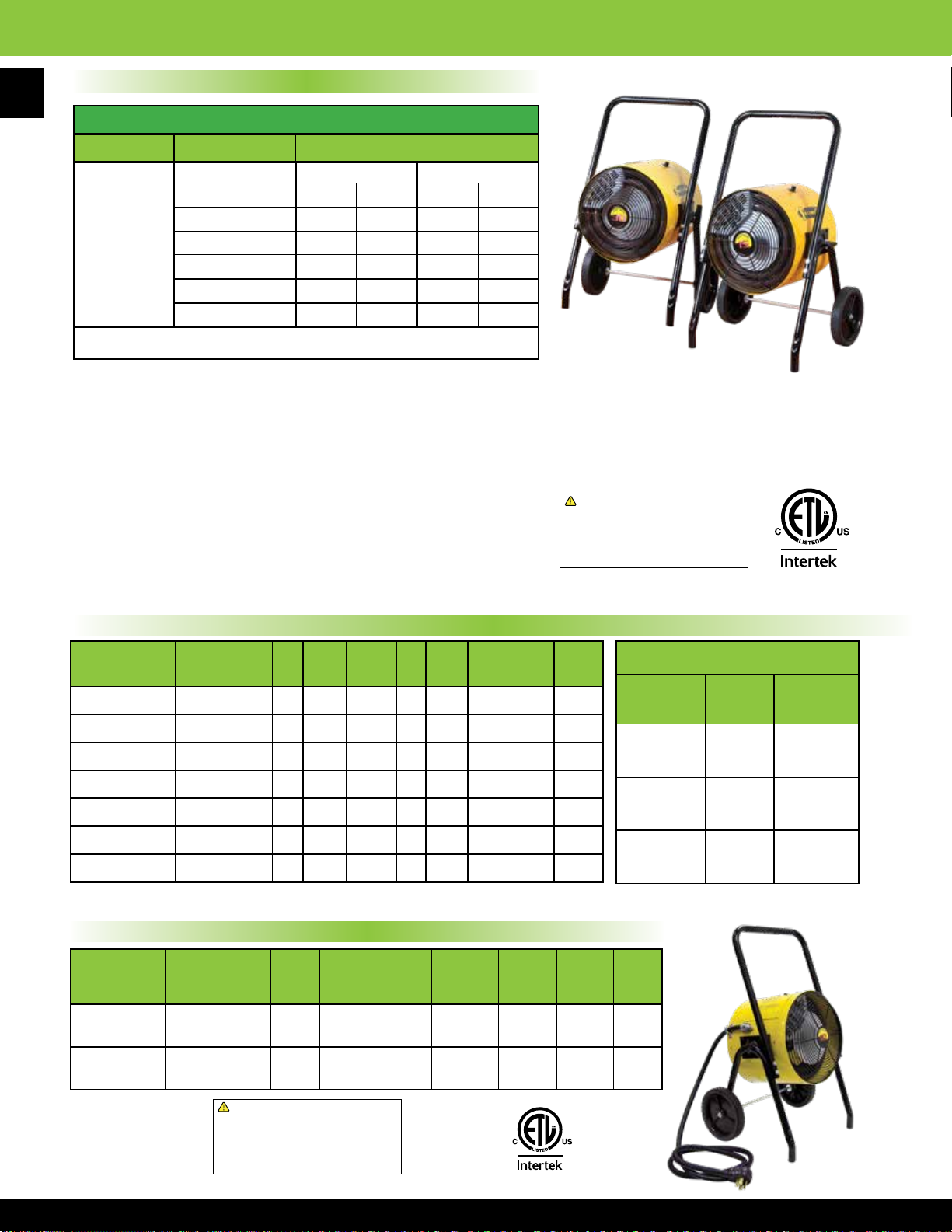
FES & YES Series Heat WaveTM Portable Electric & Wall or Ceiling Mounted Salamander
92
FES Series Product Features & Information
AVERAGE MINUTES TO ACHIEVE TEMPERATURE RISE*
BUILDING SIZE: 1000 SQ. FEET 1500 SQ. FEET 2000 SQ. FEET
TEMP RISE TEMP RISE TEMP RISE
HEATER:
9/10 KW
15 KW
30 KW
45 KW
60 KW
* Based on a 15' ceiling height - lower ceiling height will reduce time required
• Safety yellow heater enclosure with safety screens on both air intake
and output openings
• Optional 25’ long SO type cord, ready for plug attachment is available
for each model
• Long-life nned tubular heating elements
• Thermostat adjustment 40° to 100° F
• Magnetic contactor
• High-limit thermal cutout switch. / Automatic reset
• Fan only operation
• 10” wheels
• 800 CFM: 9, 10, & 15KW units - 1100 CFM-30KW units
• Made in U.S.A.
o
F 40 oF 20 oF 40 oF 20 oF 40 oF
20
70 min 140 min 105 min 210 min --- ---
47 min 94 min 71 min 142 min 94 min 188 min
23 min 46 min 35 min 70 min 47 min 94 min
10 min 30 min 20 min 35 min 35 min 40 min
6 min 15 min 14 min 11 min 24 min 28 min
THE ELECTRIC ALTERNATIVE TO
PROPANE AND KEROSENE SPACE HEATERS
!
WARNING: This product can expose you
to chemicals including nickel which is known
to the State of California to cause cancer,
and chromium, which is known to the State
of California to cause birth defects and/or
reproductive harm. For more information go
to www.P65Warnings.ca.gov.
Standard FES Models
MFG
CATALOG
NUMBER
08860110 FES-1520-3A 15 51195 208 3 42 45
08860710 FES-1524-1A 15 51195 240 1 63 45oF 4/4 69
08860210 FES-1524-3E 15 51195 240 3 36 45oF 6/4 65
08860310 FES-1548-3E 15 51195 480 3 18 45oF 12/4 65
08860410 FES-1560-3A 15 51195 600 3 15 45oF 12/4 65
08860510 FES-3048-3A 30 102390 480 3 36 45oF 6/4 83
08860610 FES-3060-3A 30 102390 600 3 29 45oF 6/4 65
9 & 10 KW, 240V, 1Phase factory pre-wired model with 10 ft. cable & straight blade range plug
MFG
MODEL
NUMBER
KW BTUs VOLTS PH AMPS
TEMP
RISE
SO
TYPE*
o
F 6/4 65
WT.
(LBS)
Corded FES Models
MFG
CATALOG
NUMBER
08744302 FES-0924-1C 9 30717 240 1 38 25
08860010 FES-1024-1CA 10 34130 240 1 42 30
MFG
MODEL
NUMBER
KW BTUs VOLTS PHASE AMPS
TEMP
RISE
OPTIONAL 25' POWER CORD*
MFG
CATALOG
NUMBER
NUMBER
03164001 SO 6/4 45
08805300 SO 4/3 70
03164201 SO 12/4 20
*Plug not included
WT.
(LBS)
o
F 55
o
F 60
MFG
MODEL
AMP
RATING
!
WARNING: This product can expose you
to chemicals including nickel which is known
to the State of California to cause cancer,
and chromium, which is known to the State
of California to cause birth defects and/or
reproductive harm. For more information go
to www.P65Warnings.ca.gov.
Page 94

FES & YES Series Heat WaveTM Portable Electric & Wall or Ceiling Mounted Salamander
45 Kilowatt FES Model
• Safety yellow heater enclosure with safety
screens on both air intake and output openings
• Optional25’longSOtypecord,readyforplug
attachment is available for each model
• Long-lifennedtubularheatingelements
• Thermostat adjustment 40° to 110° F
• Two 10” rear wheels and front locking casters
• High-limit thermal cutout switch with manual reset
• 2200 CFM
• Fan only operation feature
• Made in U.S.A.
MFG
CATALOG
NUMBER
08722202 FES-4548-3
04874002 FES-4557-3 575 46.2 6/4
*Plug not included
MFG
MODEL
NUMBER
KW BTUs VOLTS PH AMPS
45 153585
480
73.5
3
60 Kilowatt FES Model
OPTIONAL25’POWERCORD*
MFG CATALOG
NUMBER
03164301 SO 4/4
03164001 SO 6/4
TEMP
RISE
70°F
SO
TYPE*
4/4
MFG MODEL
NUMBER
dB @
2 FT.
79 198
WT.
(LBS)
Lift Assist Handles
!
WARNING: This product can expose you
to chemicals including nickel which is known
to the State of California to cause cancer,
and chromium, which is known to the State
of California to cause birth defects and/or
reproductive harm. For more information go
to www.P65Warnings.ca.gov.
93
• Safety yellow heater enclosure with safety
screens on both air intake and output openings
• Optional25’longSOtypecord,readyforplug
attachment is available for each model
• Long-lifennedtubularheatingelements
• Thermostat adjustment 40° to 110° F
• Two 10” rear wheels and front locking casters
• High-limit thermal cutout switch with manual reset
• 2500 CFM
OPTIONAL25’POWERCORD*
MFG CATALOG
NUMBER
03164301 SO 4/4
04917302 SO 2/4
• Fan only operation feature
• Made in U.S.A.
MFG
CATALOG
NUMBER
04915302 FES-6048-3
04915402 FES-6057-3 575 60.3 4/4
*Plug not included
MFG
MODEL
NUMBER
KW BTUs VOLTS PH AMPS
60 204780
480
73.5
3
TEMP
RISE
74°F
TYPE*
Standard YES Models
• Wall / ceiling mount included with unit
• Unit is ready for direct wiring
• Thermostat adjustment 40° to 100° F
• Made in U.S.A.
NEW PRODUCT
for 2020
MFG MODEL
NUMBER
SO
dB @
2/4
2 FT.
(LBS)
79 225
WT.
Lift Assist Handles
!
WARNING: This product can expose you
to chemicals including nickel which is known
to the State of California to cause cancer,
and chromium, which is known to the State
of California to cause birth defects and/or
reproductive harm. For more information go
to www.P65Warnings.ca.gov.
MFG
CATALOG
NUMBER
08860810 YES-1520-3A 15 51195 208 3 42 45
08861810 YES-1524-1A 15 51195 240 1 63 45
08860910 YES-1524-3E 15 51195 240 3 36 45oF
08861010 YES-1548-3E 15 51195 480 3 18 45
08861210 YES-3048-3A 30 102390 480 3 36
08861310 YES-3060-3A 30 102390 600 3 29
MFG
MODEL
NUMBER
KW BTUs VOLTS PHASE AMPS
TEMP
RISE
90
(LBS)
o
F
o
F
o
F
o
F 72
WT.
Wall Mounted
60
!
WARNING: This product can expose you
to chemicals including nickel which is known
to the State of California to cause cancer,
and chromium, which is known to the State
of California to cause birth defects and/or
reproductive harm. For more information go
to www.P65Warnings.ca.gov.
Ceiling Mounted
Page 95
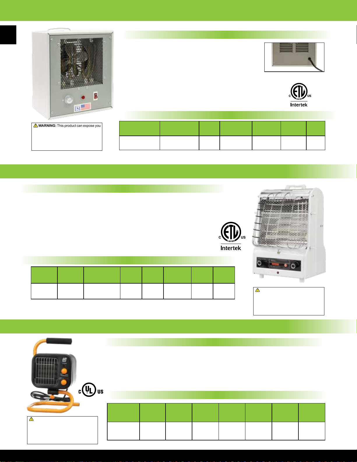
150TS Series 120 Volt Portable Electric Heater
94
!
WARNING: This product can expose you
to chemicals including nickel which is known
to the State of California to cause cancer,
and chromium, which is known to the State
of California to cause birth defects and/or
reproductive harm. For more information go
to www.P65Warnings.ca.gov.
198 Series 120 Volt Radiant and/or Fan Forced Portable Heater
Product Features
• 3-Heat settings:
- 600 Watt radiant
- 900 Watt fan forced
- 1500 Watt radiant & fan forced
• Temperature control thermostat
• Imported to TPI Corporation
specications
Product Features
• 750 / 1500 watts
• All steel construction
• Powder coat paint nish for durable,
long lasting service
• Manual reset thermal safety limit
• Illuminated ON/OFF switch
Back of heater
• Two stage thermostat
• 6 foot power cord with molded NEMA 5-15 plug
• Width: 10” Height: 11½” Depth: 6”
• Made in U.S.A.
Standard Models
MFG
CATALOG
NUMBER
01190802 150TS 120 750 / 1500 12.5 53dBA 9
*Rated at 5 feet
MFG
MODEL
NUMBER
VOLTS WATTS AMPS DECIBELS*
• Dual safety system:
- Tip over switch
- Manual reset type limit control
• 6’ long - 3 conductor cord
• 1 year limited warranty
• Width: 11”
Height: 15”
Depth: 12”
WT.
(LBS)
Standard Models
MFG
CATALOG
NUMBER
04450902 198 TMC 1500 / 900 / 600 5120 120 12.5 / 7.5 / 5 1 9
MFG
MODEL
NUMBER
WATTS
MAX
BTUs
VOLTS AMPS PHASE
178 Series 120 Volt Ceramic Fan Forced Portable Heater
Product Features
• Two heat settings: 1500W / 950W
plus fan only setting (20W)
• Temperature control thermostat
• 6’ long - 3 conductor cord
• Width: 11 1⁄4” Height: 10” Depth: 7”
Standard Models
!
WARNING: This product can expose you
to chemicals including nickel which is known
to the State of California to cause cancer,
and chromium, which is known to the State
of California to cause birth defects and/or
reproductive harm. For more information go
to www.P65Warnings.ca.gov.
MFG
CATALOG
NUMBER
04459302 178 TMC 1500 / 950 5120 120 12.5 / 7.1 1 8
MFG
MODEL
NUMBER
WATTS
MAX
BTUs
WT.
(LBS)
!
WARNING: This product can expose you
to chemicals including nickel which is known
to the State of California to cause cancer,
and chromium, which is known to the State
of California to cause birth defects and/or
reproductive harm. For more information go
to www.P65Warnings.ca.gov.
• Double safety system:
- Manual reset type limit control
- Thermal cut-off device
• Imported to TPI Corporation specications
VOLTS AMPS PHASE
WT.
(LBS)
Note: Photograph is a representation of stocked models. Actual model may vary in appearance
Page 96

188 Series 120 Volt “Milk-house” Style Fan Forced Portable Heater
Product Features
• 1300W & 1500W heat settings
plus fan only setting
• Temperature control thermostat
• 6’ long - 3 conductor cord
• Imported to TPI Corporation
specications
• Triple safety system:
- Tip over switch
- Automatic reset type limit control
- Thermal cut-off device
• Width: 10”
Height: 16”
Depth: 9 1⁄2”
Standard Models
MFG
CATALOG
NUMBER
08004102 188 TASA 1500 / 1300 5120 120 12.5 / 10.8 1 9
MFG
MODEL
NUMBER
WATTS MAX BTUs VOLTS AMPS PHASE
E3915 Series Portable Hydronic Baseboard
WT.
(LBS)
!
WARNING: This product can expose you
to chemicals including nickel which is known
to the State of California to cause cancer,
and chromium, which is known to the State
of California to cause birth defects and/or
reproductive harm. For more information go
to www.P65Warnings.ca.gov.
!
WARNING: This product can expose you
to chemicals including nickel which is known
to the State of California to cause cancer,
and chromium, which is known to the State
of California to cause birth defects and/or
reproductive harm. For more information go
to www.P65Warnings.ca.gov.
95
Product Features
• Manual reset limit control
• 2 stage thermostat (750 Watt / 1500 Watt)
• Positive On / Off switch
• Heavy duty cabinet construction
• Includes heavy duty carry handle
• Height: 9” Length: 60” Depth: 3”
Standard Models
MFG
CATALOG
NUMBER
01186702 E3915-60P 1500/750 5120 120 12.5 / 6.25 1 35
MFG
MODEL
NUMBER
WATTS
MAX
BTUs
VOLTS AMPS PHASE
483 Series 120 Volt Portable Baseboard Convection Heater
Product Features
• 1500 Watt convection heater
• Temperature control
thermostat
• Manual reset type limit control
• Power on indicator light
• 6’ long - 3 conductor cord
Standard Models
• Imported to TPI Corporation
specications
• Width: 48”
Height: 5 1⁄4”
Depth: 7 1⁄2”
WT.
(LBS)
MFG
CATALOG
NUMBER
08708802 483 TM 1500 5120 120 12.5 1 13
MFG
MODEL
NUMBER
WATTS
MAX
BTUs
VOLTS AMPS PHASE
WT.
(LBS)
!
WARNING: This product can expose you
to chemicals including nickel which is known
to the State of California to cause cancer,
and chromium, which is known to the State
of California to cause birth defects and/or
reproductive harm. For more information go
to www.P65Warnings.ca.gov.
Page 97

30 AMP Plug
NEMA #6-30P
30 AMP Plug
NEMA #6-30P
474 Series 240 Volt Dual Heat Fan Forced Portable Heater
96
!
WARNING: This product can expose you
to chemicals including nickel which is known
to the State of California to cause cancer,
and chromium, which is known to the State
of California to cause birth defects and/or
reproductive harm. For more information go
to www.P65Warnings.ca.gov.
5800 Series Garage/Workshop 240/208 Volt Fan Forced Portable Heater
• Up to 4800 Watts of heating comfort for
garage or utility room applications
• 4000 Watts available for smaller areas
• Built in bi-metal double pole
thermostat 50° to 90° range
• Steel tubular heating element
• Wall/Ceiling bracket included
• Manual reset standard
• Power on and overheat pilot lights
• Imported to TPI Corporation specications
Product Features
Product Features
• 1920W & 3840W heat settings
• Temperature control thermostat (40°-110° F)
• Manual reset type limit control
Width: 16”
Height: 16”
Depth: 8
• 6’ long - 3 conductor cord
• Imported to TPI Corporation specications
20 AMP Plug
NEMA #6-20P
Standard Models
MFG
CATALOG
NUMBER
04461802 H474TM-C 1920/3840 13106 240 8.0 / 16.0 1 20
ITEM WIDTH HEIGHT DEPTH
Heater 10.625" 11” 9.625”
Bracket 2.5” 10” 14.0”
!
WARNING: This product can expose you
to chemicals including nickel which is known
to the State of California to cause cancer,
and chromium, which is known to the State
of California to cause birth defects and/or
reproductive harm. For more information go
to www.P65Warnings.ca.gov.
MFG
MODEL
NUMBER
WATTS
MAX
BTUs
VOLTS AMPS PHASE
1
⁄2”
WT.
(LBS)
Standard Models
MFG
CATALOG
NUMBER
05034002 HF5840TC 4000/3000 13652
05033902 HF5848TC 4800/3600 15086 20 / 17.3 30 Amp
MFG
MODEL
NUMBER
WATTS
MAX
BTUs
VOLTS AMPS PHASE
16.6 / 14.4
240 / 208
1
PLUG
TYPE
20 Amp
WT.
(LBS)
17
ICH Series 240/208 Volt Construction Site/Utility Fan Forced Portable Heater
Product Features
• Temperature control thermostat with
60°F-110°F range
• 6’ long cordset
• Width: 10
5
⁄8” Height: 12 3⁄4” Depth: 10”
Standard Models
MAX
BTUs
VOLTS AMPS PHASE
!
WARNING: This product can expose you
to chemicals including nickel which is known
to the State of California to cause cancer,
and chromium, which is known to the State
of California to cause birth defects and/or
reproductive harm. For more information go
to www.P65Warnings.ca.gov.
• Operates on 240V or 208V
• Steel tubular heating element
• 43°F air heat rise
• Internal overheat thermostat
• Imported to TPI Corporation
specications
MFG
CATALOG
NUMBER
04508702 ICH-240C 4000 / 3000 13648 240 / 208 16.7 / 14.4 1 15
MFG
MODEL
NUMBER
WATTS
20 AMP Plug
NEMA #6-20P
WT.
(LBS)
Page 98
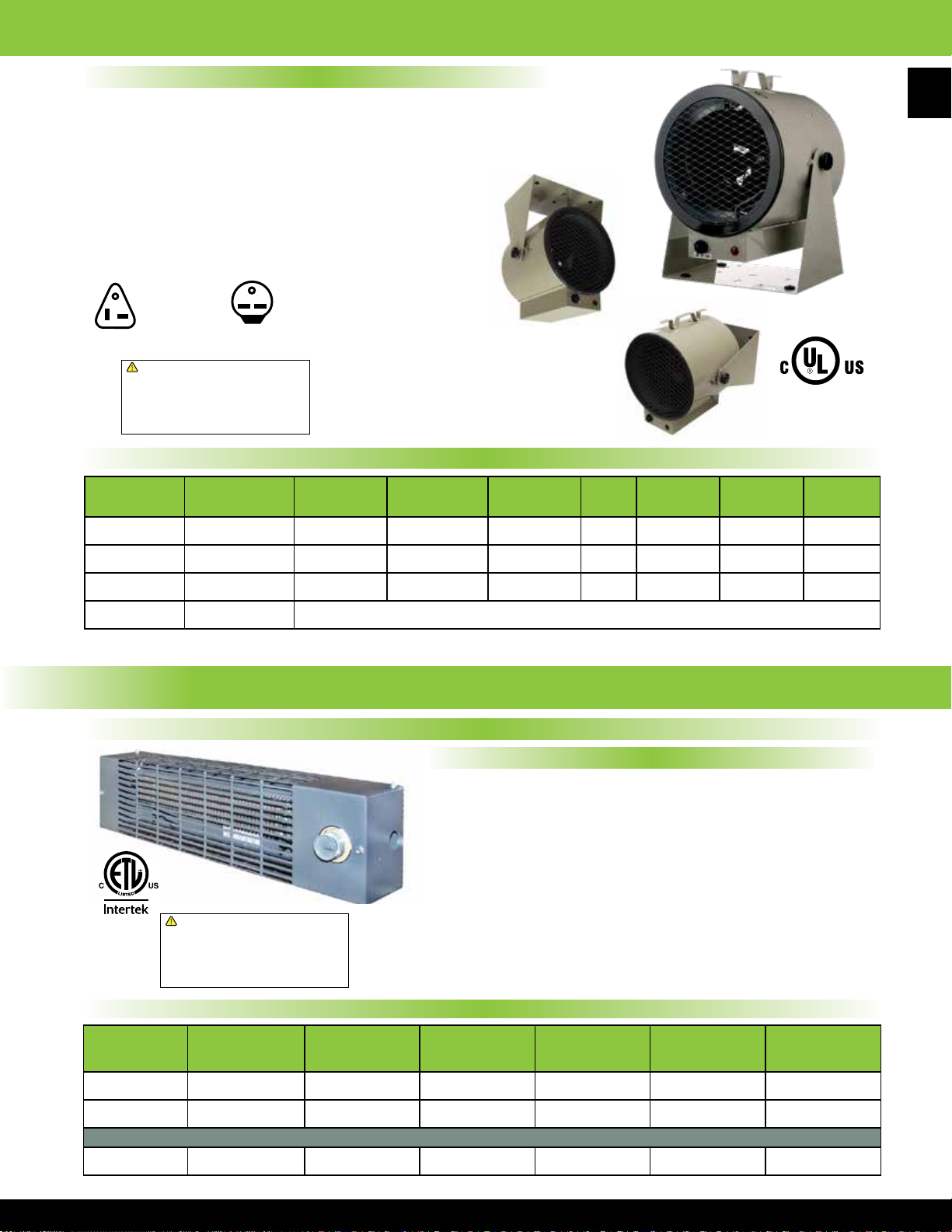
30 AMP Plug
NEMA #6-30P
680 Series “Bulldog” 240/208 Volt Fan Forced Portable Unit Heater
Product Features
• Operates on 240V or 208V
• Finned steel tubular heating element
• Internal manual reset thermal cut-out
• 6’ long cord with molded plug
• Temperature control thermostat with 60°F-110°F range
• 10’ air throw - 262 CFM
• Imported to TPI Corporation specications
• Width: 13 1⁄2” Height: 17 1⁄2” Depth: 11 1⁄2”
97
20 AMP Plug
NEMA #6-20P
HF684TC
!
WARNING: This product can expose you
to chemicals including nickel which is known
to the State of California to cause cancer,
and chromium, which is known to the State
of California to cause birth defects and/or
reproductive harm. For more information go
to www.P65Warnings.ca.gov.
30 AMP Plug
NEMA #6-30P
HF685TC,
HF686TC
Swivel base
allows unit to be
wall, oor, or
ceiling mounted
Standard Models
MFG CATALOG
NUMBER
04462802 *HF684TC 4000/3000 13652/10239 240/208 1 16.7/14.4 48
04462902 HF685TC 4800/3600 16384/12288 240/208 1 20.0/17.3 58
04463002 HF686TC 5600/4200 19107/14330 240/208 1 23.3/20.2 75
06835002 A1560 OPTIONAL WALL CEILING BRACKET FOR HF680 & ICH 240C SERIES HEATERS
*HF684TC UL listed only
MFG
MODEL
NUMBER
WATTS
MAX
BTUs
VOLTS PHASE AMPS TEMP RISE
Specialty Heaters
RPH Series Pump House Convection Specialty Heater
o
F 20
o
F 20
o
F 20
WT.
(LBS)
CATALOG
NUMBER
09990802 RPH1-5A 500 1706 120 4.2 5
09990902 RPH2-5A 500 1706 240 2.1 5
09842602 RPH22-5Ai 500 1706 220 2.3 5
!
WARNING: This product can expose you
to chemicals including nickel which is known
to the State of California to cause cancer,
and chromium, which is known to the State
of California to cause birth defects and/or
reproductive harm. For more information go
to www.P65Warnings.ca.gov.
MFG
MFG
MODEL
NUMBER
Product Features
• Provides protection against freezing for pump houses,
utility rooms, relay stations, construction sheds, etc.
• Stainless steel heating element and Aluminum ns
• Automatic temperature control thermostat
with a 30°F to 140°F range
• Powder coated epoxy steel case
• Dimension 20” x 5
1
⁄2” x 4”
• Over heat protection thermal fuse
• Made in U.S.A.
Standard Models
WATTS BTUs VOLTS AMPS
International Models
WT.
(LBS)
Page 99

98
Specialty Heaters
FH Series In-Floor Fan Forced Specialty Heater
Product Features
• Powder coated 20 gauge steel case
• 14 gauge grill
• Steel spiral nned heating element
• Auto reset thermal cut out with visual alarm
1
• Floor opening: 14
⁄8” x 7 1⁄4” x 7 3⁄8”
• Grill dimensions: 15 13⁄16” x 8 13⁄16”
• Made in U.S.A.
MFG
CATALOG
NUMBER
03782302 FH15
03782702 FH1T Single Pole Integral Thermostat Kit (40°-110°F) 1
MFG
MODEL
NUMBER
WATTS BTUs VOLTS AMPS
750 2560 120 6.25
1500/1125 5120 / 3840 240/208 6.25/5.41
OPTIONAL FIELD INSTALLED THERMOSTATS
TSH Series Fan Forced Kickspace Specialty Heater
!
WARNING: This product can expose you
to chemicals including nickel which is known
to the State of California to cause cancer,
and chromium, which is known to the State
of California to cause birth defects and/or
reproductive harm. For more information go
to www.P65Warnings.ca.gov.
Standard Models
WT.
(LBS)
151500 5120 120 12.5
Product Features
• Fits into softs, stair risers or under utility cabinets
• Finned steel heating element
!
WARNING: This product can expose you
to chemicals including nickel which is known
to the State of California to cause cancer,
and chromium, which is known to the State
of California to cause birth defects and/or
reproductive harm. For more information go
to www.P65Warnings.ca.gov.
• Manual reset thermal cut-out
• Recessed opening: 22
• Grill dimensions: 23
3
⁄8” x 3 5⁄8” x 11 1⁄2”
7
⁄8” x 3 5⁄16”
• Zero inch clearance for insulation
• Made in U.S.A.
Standard Models
MFG
CATALOG
NUMBER
03818002 TSH20J
09701702 TSH20JW Above Model with White Grill
03783702 TSH1TX Single Pole Integral Thermostat Kit (40°-100°F) 1
03783802 TSH2TX Double Pole Integral Thermostat Kit (40°-100°F) 1
MFG
MODEL
NUMBER
WATTS BTUs VOLTS AMPS
1500 / 1000 5120 / 3412 120 12.5 / 8.4
1500 / 750 5120 / 2560 208 7.2 / 3.6
2000 / 1000 6284 / 3412 240 8.4 / 4.2
OPTIONAL FIELD INSTALLED THERMOSTATS
(LBS)
CF-C Series TPI Commercial Air Curtains
Features
• Super thin body, full metal housing
• Cross ow, 2-speed fans
• Adjustable air deector
• Mechanical control
• Units are 120V at 60Hz
!
WARNING: This product can expose you
to chemicals including nickel which is known
to the State of California to cause cancer,
and chromium, which is known to the State
of California to cause birth defects and/or
reproductive harm. For more information go
to www.P65Warnings.ca.gov.
WT.
16
Standard Models
MFG
CATALOG
NUMBER
08764402 CF35-C 300 1177 942 2560 1968 67 65 35”
08764502 CF47-C 350 1648 1295 2560 1968 69 67 47” 43
08764602 CF59-C 400 2119 1648 2560 1968 71 69 59” 48.5
MFG
MODEL
NUMBER
WATTS
CFM FPM NOISE LEVEL (dB) DIMENSIONS
HIGH LOW HIGH LOW HIGH LOW “L” “W” “H”
8 3⁄4” 10 1⁄4”
WT.
(LBS)
33.1
Page 100

CF & CFH Series Variable Speed Air Curtains
Product Specications
CABINET & CONSTRUCTION: Shall be constructed of 20 gauge
rigid steel with baked on epoxy powder coat paint for durability.
Made in U.S.A.
DISCHARGE VANES: Shall extend the entire width of the unit and
be adjustable for optimum performance of air ow.
BLOWERS: Shall be forward curved centrifugal type, DWDI with
corrosion resistance scroll and wheel.
MOTORS: Shall be heavy duty, PSC, direct drive high efciency and
designed for use with SCR controllers. Motors shall be permanently
lubricated for long life
and have thermal over
load protection. Motor
shall have double
insulation protection
for quieter operation.
Quick disconnects
shall be supplied to
accommodate easy
installation and service
of motor.
SCR SPEED
CONTROLLER:
Supplied on all units
compatible with the
motor with low end
adjustment for air
volume control and
savings in power
consumption.
ELECTRIC HEAT
(OPTIONAL):
Electric heater
available as eld
installed option.
Electric heater shall
be steel sheath
element with helical
wound steel ns
for maximum heat
transfer and safety.
Air Curtain with
Heater Module
NOTE: All heating
sections are
constructed of totally
enclosed n tubular
elements for safety and
longer operating life.
With heating section
installed, unit becomes
a 24 Volt control unit
and can utilize a low
voltage thermostat for
control of heating.
NOTE: For 72” through
120” units, order
multiple heater modules
corresponding to
the actual air curtain
models
MFG
CATALOG
NUMBER
06712002 36 CF36 3288/455 2672/333
06712102 48 CF48 4168/786 4515/766 1606/583 4.4/3.6 519/189 82
06712202 60 CF60 4168/764 6544/931 1636/562 4.4/3.8 509/199 90
06712302 36 CFHD36 3288/1120 2672/819
06712402 48 CFHD48 4256/929 4611/906 1662/500 5.9/4.8 586/168 85
06712502 60 CFHD60 4256/924 5763/1126 1652/509 5.2/4.4 708/172 93
Model # Unit Width KW Volts Phase
CFHTR 36 10.0 208 3
MFG
MODEL
SIZE
(in)
STANDARD UNITS: 1/2 HP MODELS - UP TO 10’ HIGH DOORWAYS - WITHOUT HEAT SECTION
72 2 EA: CF36 3288/455 5344/666 1659/620 7.8/6.8 944/308 148
96 2 EA: CF48 4168/786 9030/1532 1606/583 8.8/7.2 1038/378 164
108 3 EA: CF36 3288/455 8016/999 1659/620 11.7/10.2 1416/462 222
120
HEAVY DUTY UNITS: 3/4 HP MODELS - UP TO 12’ HIGH DOORWAYS - WITHOUT HEAT SECTION
72 2 EA: CFHD36 3288/1120 5344/1638 1689/603 8.8/8.6 1206/384 154
96 2 EA: CFHD48 4256/929 9222/1812 1662/500 11.8/9.6 1172/336 170
108 3 EA: CFHD36 3288/1120 8016/2457 1689/603 13.2/12.9 1809/576 231
120
| | | | |
HEATER
WIDTH
CFHTR
36, 48, or 60 Inch Width
NOTE: 12KW MAXIMUM ON 36” WIDTH UNITS
MFG
MODEL
NUMBER
1 EA: CF48 4168/786
2 EA:CF36 2672/333 1659/620
1 EA: CFHD48 4256/929
2 EA: CFHD36 3288/1120 1689/603
EXAMPLE
KW VOLTS
3
5
7.5
10
12
15
FT. / MIN.
HI - LOW
208
240 7.2 9.0 15 14
480 3.6 4.5 15 14
277
208 14.4 18.0 20 12
240 12.5 15.6 20 12
208
240 12.0 15.0 20 12
480 6.0 7.5 15 14
277
208 24.0 30.0 35 8
240 20.8 26.6 30 10
208
240 18.0 22.5 25 10
480 9.0 11.3 15 14
277
208 36.0 45.0 50 6
240 31.2 39.0 45 8
208
240 24.0 30.1 35 8
480 12.0 15.0 20 12
277
240 41.6 52.0 60 6
208
240 28.8 36.0 40 8
480 14.4 18.0 20 12
277 1 43.3 54.1 60 6
208
240 36.0 36.0 55 6
480 18.0 18.0 30 10
!
WARNING: This product can expose you
to chemicals including nickel which is known
to the State of California to cause cancer,
and chromium, which is known to the State
of California to cause birth defects and/or
reproductive harm. For more information go
to www.P65Warnings.ca.gov.
PHASE
3
1
3
1
3
1
3
1
3
3
NOZZLE
CFM
9859/1432
9955/2544
HEATER
AMPS
10.8 13.5 15 14
13.8 17.25 20
18.0 22.5 25 10
20.8 26.0 30
27.0 33.8 40 8
27.7 34.4 40
36.1 45.1 50 6
33.3 41.6 45
41.6 52.0 60
VOLTS
120
120
Use the example shown (left) to order unit
with heat section by specication
MINIMUM CIRCUIT
8.3 10.4 15
AMPS
RPM
HI - LOW
1659/620 3.9/3.4 472/154 74
1606/583
1689/603 4.4/4.3 603/192 77
1662/500
AMPS
HI - LOW
12.2/10.4 1982/497 230
14.7/13.4 2981/552 239
MAXIMUM
FUSE AMPS
WATTS
HI - LOW
BTU/H
10,239
17,075
25,597
34,130
40,956
51,195
WT.
(LBS)
75°C WIRE
AWG
14
12
10
8
8
6
99
 Loading...