

TPI OCH–46-120V-SSE, OCH–46-208V-SSE, OCH–46-240V-SSE, OCH–46-277V-SSE, OCH-57-208V-SSE User Manual
...Page 1
IMPORTANT SAFETY
future reference.
*EXCLUDING RESIDENCES
TPI Corporation
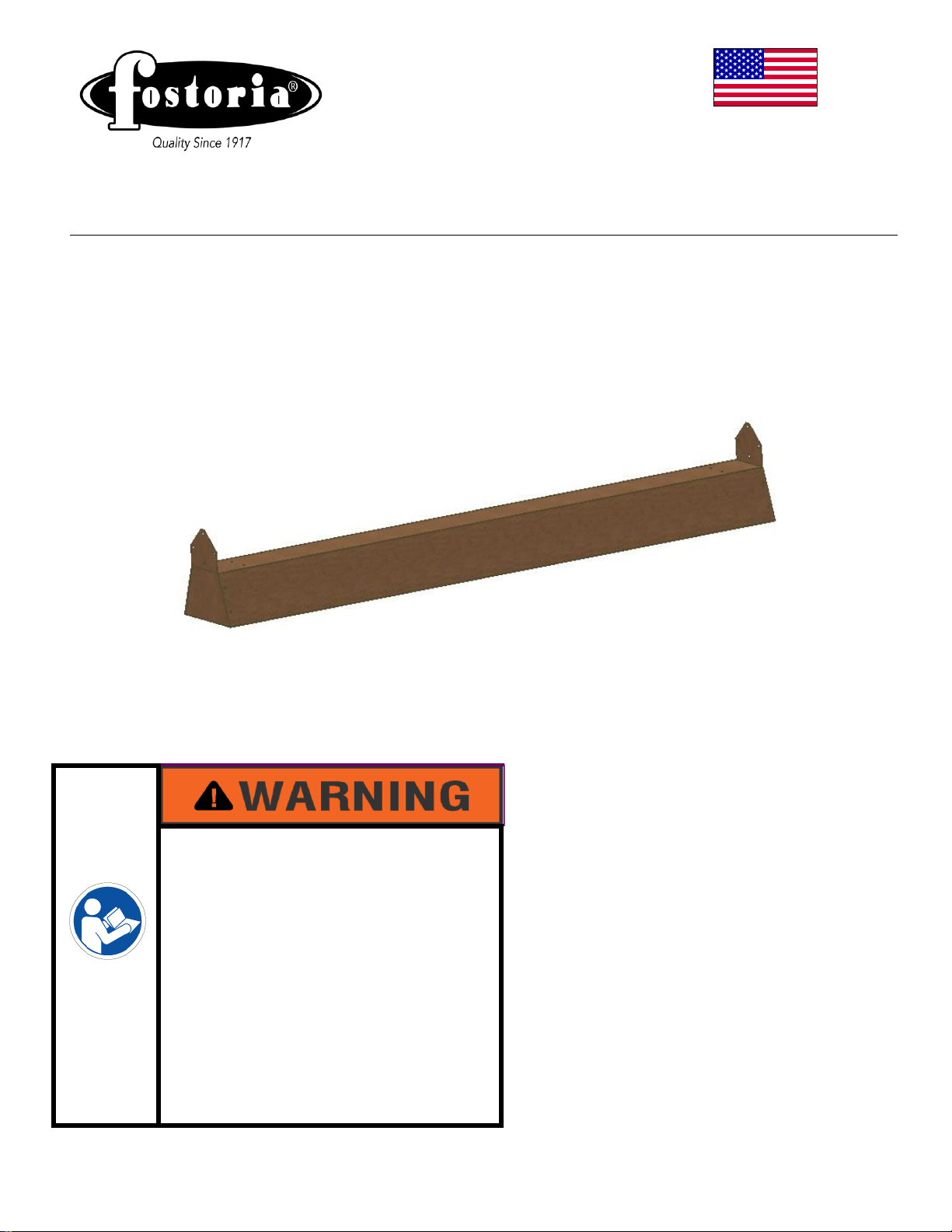
OCH-SSE series
Indoor * and Outdoor Comfort Heaters
REFER TO COMPLETE
Issue Date: 10-02-98 Rev. Date: 5-07-14 Rev. Level: 06 ECO 1-6950 OIPM P/N 8304 Page 1 of 9
INFORMATION INSIDE
• Serious injury or death possible
• Read, understand, and follow all
safety information and
instructions in this manual
before using or servicing this
product.
• Retain these instructions for
P.O. Box 4973
Johnson City, TN 37601
www.tpicorp.com
Direct Wired Units
INDEX OF
INFORMATION ON
PAGE 2
Page 2
INDEX
Index
Page 2
Safety Signal Word Definitions
Page 2
Important Instructions
Page 3
Specifications
Page 4
Quartz Tube Installation
Page 5
Heater Installation
Pages 5 & 6
Wiring
Page 7
Maintenance
Page 8
Troubleshooting
Page 8
Warranty
Page 9
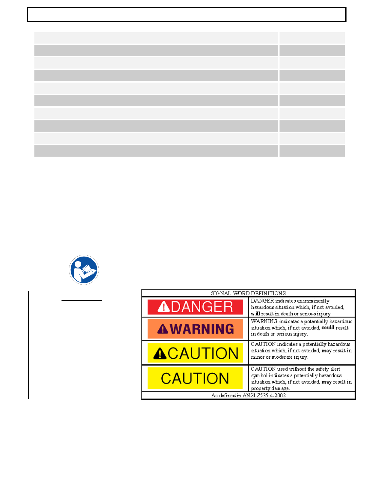
ATTENTION:
The table to the right provides
can be found throughout this
are generally used in conjunction
to the text for that particular hazard.
definitions of the signal words that
manual. These signal words are
used to express the severity of the
hazard at hand. The signal words
with safety symbols that correspond
As you read this manual, refer back
to this table when you are unsure of
the signal word definition.
Issue Date: 10-02-98 Rev. Date: 5-07-14 Rev. Level: 06 ECO 1-6950 OIPM P/N 8304 Page 2 of 9
Page 3

IMPORTANT INSTRUCTIONS
When using electrical appliances, basic precautions should always be followed to reduce the risk of fire,
electrical shock, and injury to persons, including the following:
1. Read all instructions before using this heater.
2. CAUTION:
papers, clothes and curtains away from the heater. For safe and efficient operation, heaters
must be mounted a minimum of 12" from a vertical surface, a minimum of 6" from the ceiling,
A minimum of 72" from direct radiation to combustibles, and a minimum of 2.4M (7.87’) above
the floor. Heaters must be at least 36” apart.
ATTENTION- HAUT TEMPÉRATURES. Pour un fonctionnment súr et efficace. CHAUFFE doit étre monté un
Minimum de 12 “d”une surface vertical, un minimum de 6” du plafond, un minimum de
72 “DE RADIATION DIRECTE DE COMBUSTIBLES ET UN MINIMUM DE 2.4M (7.87’) FROM LE
SOL. NE PAS UTILISER CETTE BOITE DE CABLAGE. UTILISER 75°C FIL MINIMUM.
DÉBRANCHER before ENTRETIEN.
3. Extreme caution is necessary when any heater is used by or near children or invalids and whenever the
heater is left operating and unattended.
4. Do not operate any heater after it malfunctions, has been dropped or damaged in any manner. Return heater to
authorized service facility for examination, electrical or mechanical adjustment, or repair.
5. Do not use outdoors.
6. To disconnect heater, turn controls to off, and turn off power to heater circuit at main disconnect panel (or
operate internal disconnect switch if provided).
7. Do not insert or allow foreign objects to enter any ventilation or exhaust opening as this may cause an
electric chock or fire, or damage the heater.
8. To prevent a possible fire, do not block air intakes or exhaust in any manner.
9. A heater has hot and arcing or sparking parts inside. WARNING: Do not use it in area where gasoline, paint,
or flammable liquids are used or stored.
14. Use this heater only as described in this manual. Any other use not recommended by the manufacturer
may cause fire, electric shock, or injury to persons.
10. This heater may include an audible or visual alarm to warn that parts of the heater are getting excessively, hot
If the alarm sounds (or illuminates), immediately turn the heater off and inspect for any objects on or adjacent
to the heater that may have blocked the airflow or otherwise caused high temperatures to have occurred.
DO NOT OPERATE THE HEATER WITH THE ALARM SOUNDING (OR ILLUMINATING).
11. SAVE THESE INSTRUCTIONS
High temperatures. Keep cords and all other combustible material, such as furniture,
Issue Date: 10-02-98 Rev. Date: 5-07-14 Rev. Level: 06 ECO 1-6950 OIPM P/N 8304 Page 3 of 9
Page 4

SPECIFICATIONS
DESCRIPTION
Fostoria multi-purpose OCH-SSE series electric
heating for many commercial and industrial
tube emitter included with the heater, are easily
excellent radiant output. They are built with
EXPLOSION HAZARD
A
B
C
Model
P/N
Tube P/N
Watts
Volts
Amps
Dim A*
Dim B
Dim C
OCH–46-120V-SSE
04805202
04432302
1500
120
12.5
48.0”
5.375”
6.500”
OCH–46-208V-SSE
04805302
04418102
2000
208
9.6
48.0”
5.375”
6.500”
OCH–46-240V-SSE
04805402
04418002
2000
240
8.3
48.0”
5.375”
6.500”
OCH–46-277V-SSE
04805502
04419302
2000
277
7.2
48.0”
5.375”
6.500”
OCH-57-208V-SSE
04805702
04416602
3000
208
14.4
59.0”
5.375”
6.500”
OCH-57-240V-SSE
04805602
04414702
3000
240
12.5
59.0”
5.375”
6.500”
OCH-57-277V-SSE
04805802
04419402
3000
277
10.8
59.0”
5.375”
6.500”
OCH-57-480V-SSE
04805902
04419502
2250
480
4.7
59.0”
5.375”
6.500”
6FT. CORDSET EXITS
OPTIONAL MOUNTING
BRACKET SHOWN
infrared heaters are designed to provide efficient spot
applications. All models operate with a si ngle quartz
installed, and are equipped with spectral reflectors for
corrosion-resistant materials and are listed for both
INDOOR (excluding residences) AND OUT DOOR
applications in the USA and Canada.
Housing
Finish
Reflectors, end caps
Suspension
24 ga. Type 304 Grain line Stainless Steel
No. 3
0.040” gold anodized aluminum
Adjustable Mounting Bracket or Chain
Issue Date: 09-25-07 Rev. Date: 05-07-14 Level: 06 ECO 1-6950 OIPM P/N: 8304 Page 4 of 9
FIRE HAZARD
• Serious injury or death
may occur.
• Do not use in locations
containing hazardous
atmospheres.
• Do not use inside
residences.
END OF HEATER
(NOT SHOWN)
Page 5

QUARTZ TUBE INSTALLATION
ELECTRICAL SHOCK
HEATER INSTALLATION
Install heater so that the quartz tubes are
horizontal. Failure to do this may cause the
heating element within the tube to sag and cause
premature burnout.
FIRE HAZARD
MINIMUM INSTALLATION CLEARANCES
These heaters MUST be installed as follows:
NOTE: For optimum spot heating performance, it is recommended that the distance from the floor
Each heater is equipped with two black hi-temperature silicone lead
wires and one green lead wire for ground termination. Make sure
power source conforms to the heater requirements. Use only
Fostoria quartz t ube s.
shaped slots in heater
On each end of the quartz tube, place (1) lead wire ring
terminal, (1) lock washer and ( 1) hex nut o n the threaded stud
(see image below). Lock washers and
the
NOTE – Use a second wren ch to hold the inner hex nu t in place
while tightening the o uter hex n ut.
this
connection will cause the element to fail prematurely.
Attach reflector end caps to both ends of housing using
the (4) screws provided in hardware package.
QUARTZ TUBE
LOCK WASHER
HEX NUT
RING TERMINAL
12 inches minimum from a vertical surface
72 inches minimum from ANY combustible
3 inches minimum from the ceiling
36 inches minimum from other heaters
should be approximately 7 to 9 feet for OCH-46 models, and 8 to 10 feet for OCH-57 models.
Issue Date: 09-25-07 Rev. Date: 05-07-14 Level: 06 ECO 1-6950 OIPM P/N: 8304 Page 5 of 9
• Serious injury or death
• Disconnect from electrical
• Reflector end caps must be
material
HAZARD
may occur.
supply before installing or
servicing this heater.
installed prior to powering
the unit; refer to note #3.
1. Insert quartz tube in the “L”-
housing.
2.
and tighten securely
hex nuts are provided in hardware package.
One lead wire is already installed in your heater;
3.
second lead wire is located in the hardware package.
Failure to securely tighten
• Serious injury or death may
occur.
• Read and follow clearances
shown in box at left for ALL
OCH series heater
installations.
• Do not use inside residences.
Page 6

HEATER INSTALLATION continued
SUSPENSION ALTERNATIVES
Your OCH-SSE series heater can be mounted with either
figures 1 & 2, mount your adjustable mounting
nds to the inside). Once mounted,
assemble the heater to brackets (figure 3) with
4. Cut the 16ga. chains (two 4 foot chains are
Figure 1: end view
Figure 2: side view
Figure 4: end view
Install heater so that the quartz tubes are
horizontal. Failure to do this may cause the heating
element within the tube to sag and cause premature
burnout.
ELECTRICAL SHOCK
Adjustable mounting brackets
Figure 3: mounting view
10-32 Nylon
Lock Nut
Mounting
Bracket
10-32 x ½”
Screws
adjustable mounting brackets or chain suspension. Both
options are included with your heater.
Standard Mounting:
In the hardware bag shipped with your heater you will
find two adjustable mounting brackets and fastening
hardware. Using the mounting centers specified in
brackets (be
mounting hardware, these brackets enable the heater to
be angled in 15-degree increments up to 45 degrees.
Chain Suspension:
The heater can also be chain-hung as shown in figure
provided) to desired length. Attach chains to heater
with “S”-hooks provided and suspend from overhead
structure. Crimp “S”-hooks closed after assembly.
Issue Date: 09-25-07 Rev. Date: 05-07-14 Level: 06 ECO 1-6950 OIPM P/N: 8304 Page 6 of 9
HAZARD
• Serious injury or death
may occur.
• Disconnect from electrical
supply before installing or
servicing this heater.
• Read and follow
installation clearance
requirements on page 4.
Page 7

INTERNAL WIRING DIAGRAM
OCH-SSE heaters are equipped with two hi-temperature
silicone lead wires and a bonding* (ground)
termination.
Supply wires must be copper and rated for at
least 90º C.
Fasten field bonding wire to the ground screw
Terminate L1 and L2 field wires to the power
wires of the heater with wire nuts (customer
ELECTRICAL SHOCK
Make certain the power source
conforms to specifications on the
Do not depend on a thermostat or
other switch as the sole means of
yellow wire to a live or “hot”
*Bonding is the term that describes the completion
of the electrical circuit back to its source, which
allows a breaker or fuse t o clear if a s hort occurs in
the line.
For totally exposed outdoor applications (not ceiling
protected) all conduit and fittings must be NEMA
Type 4 or equal.
The junction box cover gasket
must be used to maintain the outdoor rating of the
heater.
WIRING
TOTALLY EXPOSED OUTDOOR APPLICATIONS
Power
Hi-temp. wires
Junction Box
(located on
heater)
Quartz Lamp
Hi-temp. lead wire from
Required conduit size: ½”
All conduit fittings and conduit are supplied by the
customer.
CONDUIT
Issue Date: 09-25-07 Rev. Date: 05-07-14 Level: 06 ECO 1-6950 OIPM P/N: 8304 Page 7 of 9
1.
and assure tight connection.
2.
supplied)
inside of
Supply
(supplied with unit)
hardware package
HAZARD
heater label.
disconnecting power when installing
or servicing hea ter. Always open the
safety switch and lock it open.
All wiring must be performed by a
licensed electrician.
Never connect the green or green-
conductor.
• Serious injury or death
may occur.
• Disconnect from electrical
supply before installing or
servicing this heater.
• This appliance must be
connected to a properly
bonded (grounded)
electrical source.
• Read and follow all safety
information in box below.
Page 8

MAINTENANCE
1. Always disconnect heater from power
Periodically clean the reflector with a
dampened soft cloth using mild detergent.
ELECTRICAL SHOCK
TROUBLESHOOTING
SYMPTOM
POSSIBLE CAUSE(S)
CORRECTIVE ACTION
supply before performing any maintenance
or service.
2.
Rinse with water and wipe dry with a clean
soft cloth.
Element does not energize.
Not enough heat.
Too much heat.
Hot spot in tube.
1. Defective element.
2. Improper connection.
1. Heater too small for application.
2. Heater mounted too high or too far.
1. Heater too large for application.
2. Heater mounted too low or too close.
1. Heater is not level.
2. Grease or moisture on tube.
• Serious injury or death
HAZARD
may occur.
• Disconnect from electrical
supply before installing or
servicing this heater.
1. Replace element.
2. Check connection to power outlet.
1. Add additional heater(s)
2. Decrease mounting height or
distance.
1. Replace with smaller heater.
2. Increase mounting heig ht or distance.
1. Adjust to a level mount.
2. Clean tube-repla ce if probl em
persists.
Issue Date: 09-25-07 Rev. Date: 05-07-14 Level: 06 ECO 1-6950 OIPM P/N: 8304 Page 8 of 9
Page 9

HEATING PRODUCTS WARRANTY COVER AGE
Heating Products Elements in
Thermostats and Contr ols
10 Years
VENTILATION PRODUCTS WARRANTY COVERAGE
Series HD or HDH Fans
All other Ventilation Products
5 Years
1 Year
LIMITED WARRANTY
Products manufact ured by T PI Corporat ion are war ranted t o the origi nal consum er to be free f rom defec ts in m aterial
and workmanship for twelve (12) months from the original purchase date.
The TPI limited warrant y does not cover prod ucts that have been m odified outside of our fac tory, damage or failure
caused by acts of God, ab use, misuse, connected to or placed on o ther than rated voltage, abnorm al usage, fault,
installation, failure t o follow suggeste d maintenance procedures enclose d with the prod uct, improper m aintenance or
any repairs other than those provided by an authorized TPI service center.
There are no obligations or liabilities on the part of the Corporation for consequential damages arising out of
or in connection with the use or performance of the product or other indirect damages with respect to loss of
property, revenues, profit, costs of removal installation, or reinstallation.
All implied warranties with respect to TPI products, including implied warranties for merchantability and
implied warranties for fitness, are limited in duration to twelve (12) months from original date of purchase,
except those products or parts of products which are warranted for long periods thereon.
Some states do not allow the exclus ions or limitation of incidental or consequ ential dam ages and some states do not
allow limitations on how long an implied warranty lasts. The above exclusions or limitations may not apply to you.
During the warrant y period, TPI Corporat ion will, at its sole option, repair or replace any defecti ve parts or products
returned, freight pr epaid, to the TPI Corporat ion factory or such other l ocations as TPI Corporation may designate.
Returned products must be packaged carefully and TPI Corporation shall not be responsible for damage in transit.
When returning parts, the owner must provide the model number of the product and nature of difficulty being
experienced. This warran ty does not obligate TPI Corporation to bear the cost of labor in replacing any assem bly,
unit or component part thereof, nor does the company assume any liability for secondary charges, expenses for
installing or removal, fr eight or dam ages. T here will be c harges render ed for produc t repairs m ade after the warr anty
period has expired. Proof of purchase, includi ng dat e, m us t ac c om pan y request f or in-warranty service. In an y event,
TPI Corporation’s m aximum liabilit y shall not in an y case exceed the lis t price for t he product claim ed to be defec tive.
This warranty gives to you specific legal rights and you may have other rights, which may vary from state to state. For
the name of your near est authori zed TPI C orporat ion ser vice center, p lease write to T PI Corpor ation, P.O. Box 497 3,
Johnson City, TN 37602.
Baseboards
All other Heating Products
Series UHP or IHP Fans
Issue Date: 09-25-07 Rev. Date: 05-07-14 Level: 06 ECO 1-6950 OIPM P/N: 8304 Page 9 of 9
1 Year
2 Years
3 Years
 Loading...