

Page 1
Service Manual
for DC-Inverter
KFR-26GW/ZBP & 34GW/ZBP
INVERTER WALL SPLIT
Technical specifications
Working range
Indoor unit
Outdoor unit
Refrigeration cycle diagram
Main function
page 64
page 66
page 67
page 68
page 69
page 70
System control
Wiring diagram
Faults & self-diagnoses
Service parts list
page 71
page 78
page 80
page 85
64
Page 2
Technical specifications
Heat pump
Model
Cooling capacity
Heating capacity
Rated power input
Cooling
Heating
Rated current
Cooling
Heating
Operation frequency
Power
Air flow(indoor/high speed)
Noise(indoor/outdoor)
W
Btu/h
W
Btu/h
W
A
Hz
3
m /h
dB(A)
Refrigerant R410A
9000BTU 12000BTU
KFR-26GW/AZBP KFR-34GW/AZBP
2600(900~3200) 3500(1000~3700)
8870(3100~11000) 12000(3412~13000)
3400(1000~4000) 4100(1000~4500)
12000(3412~14000) 140003412~15400)
780(250~1100) 1020(260~1320)
950(250~1320) 1130250~1500)
3.7 4.80
4.5 5.30
28~95
220/240V/1/50Hz
520
İ42/52
Refrigerant(R410A˅
Refrigerant tube size
Liquid
Gas?
Connecting wire
Power wire
Drain hose(Indoor/Outdoor)
Dimension(WhHhD)
Indoor
Outdoor
Weight
Indoor
Outdoor
inch
mm
mm
mm
mm
kg
g
2
2
770 910
ʾ
1/4
ʾ
3/8
3
h1.0+1h0.75 3h1.5+1h0.75
3
h1.0/10A 3h1.5/16A
I. d¶16
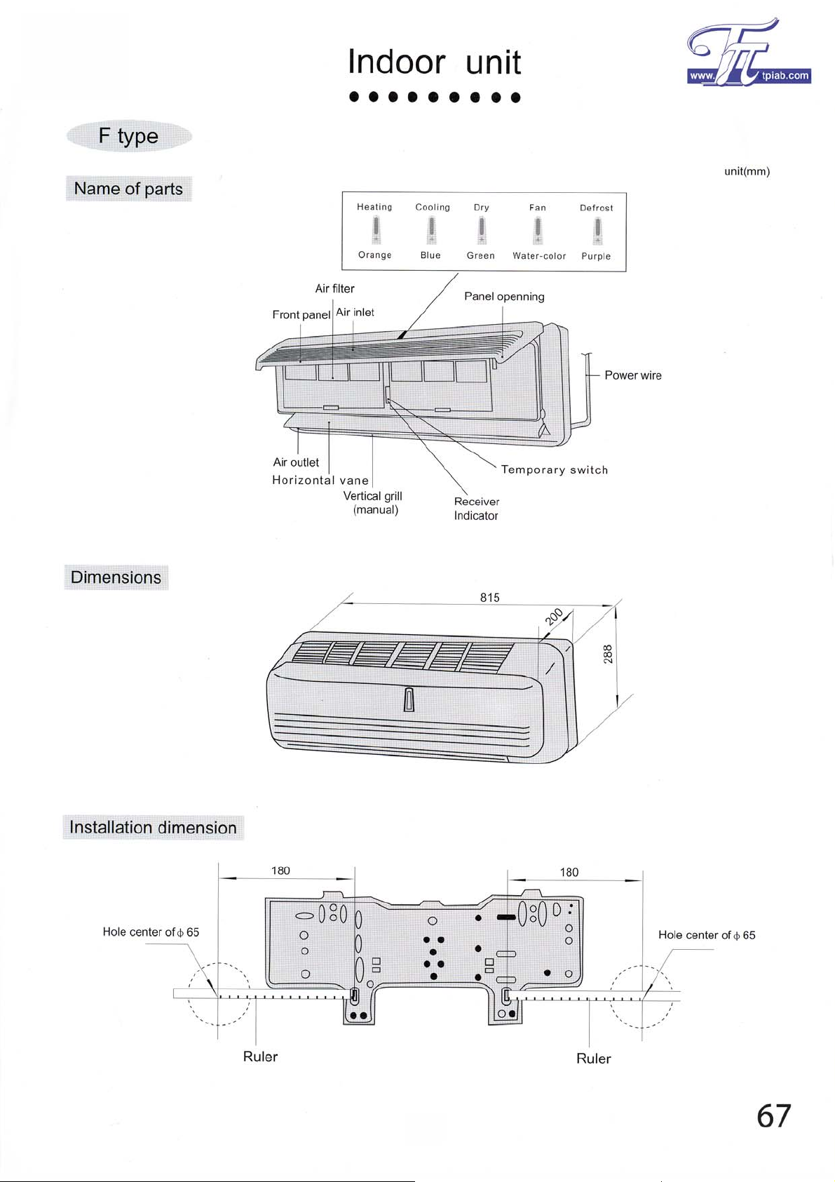
815
h288h210
820
h540h320
10.5 10.5
32
1/4
1/2
35
Note
1
Rated cooling capacity under below conditions˖
Indoor temp:27ćDBˈ19ćWB˗Outdoor temp:35ćDBˈ24ćWB.High speed;4-meter connecting pipe.
2
Rated heating capacity under below conditions˖
Indoor temp:20ćDB;Outdoor temp:7ćDBˈ6ćWB.High speed;4-meter connecting pipe.
3
We get the noise under heating model meantime.The fan runs at high speed.
ʾ
ʾ
65
Page 3
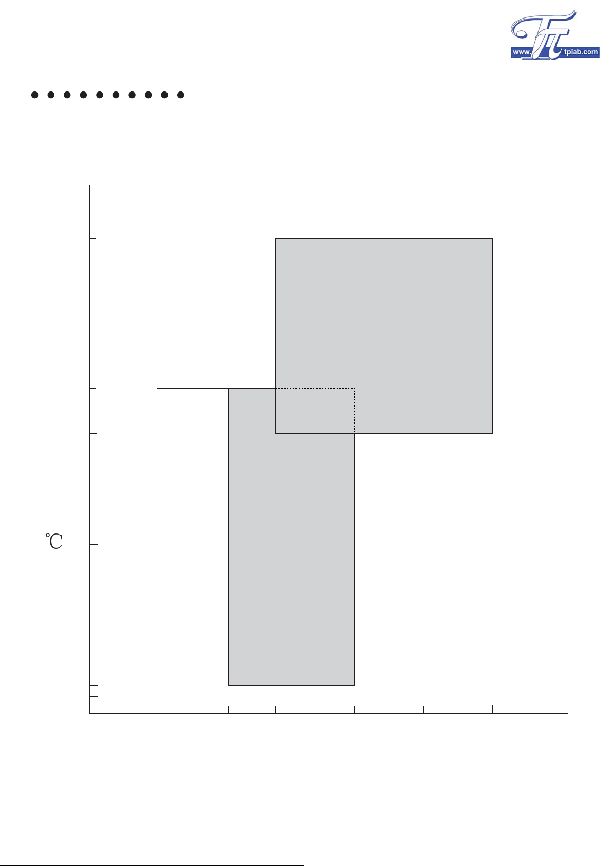
Working range
43
Max.operation temp
Cooling
Outdoor side temp.
24
21
Max.operation temp
Min.operation temp
ć
10
Min.operation temp
-7
-10
Heating
20 27 30 32
21
Indoor side temp.ć
66
Page 4
Page 5
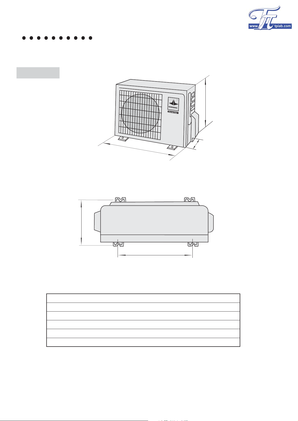
Outdoor unit
Outdoor unit
unit(mm)
H
L2
W
L1
D
Dimension
W
H
D
1
L
L2
9000Btu
760
528
256
538
283
12000Btu
760
528
256
538
283
68
Page 6
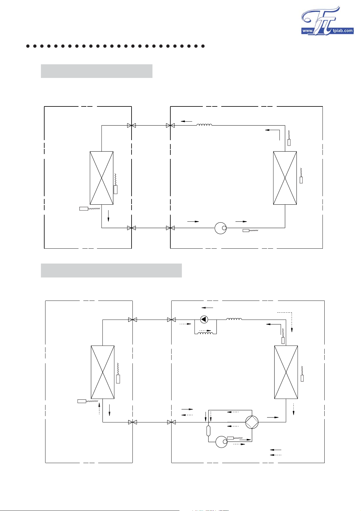
Refrigeration cycle diagram
COOLING ONLY MODELS
Indoor unit
Indoor
Exchanger
Indoor air thermo
Indoor
pipe
thermo
Liquid side
2-way valve
3-way valve
Gas side
Cooling capillary
Compressor
Outdoor unit
Outdoor
Exchanger
discharge thermo
Outdoor
pipe
thermo
Outdoor
air
thermo
COOLING AND HEATING MODELS
Indoor unit
Liquid side
2-way valve
Indoor
pipe
thermo
Indoor
Exchanger
Indoor air thermo
Gas side
3-way valve
Check valve(Heating model)
Heating capillary
Accumulator
Outdoor unit
Cooling capillary
discharge thermo
Outdoor
pipe
thermo
Outdoor
Exchanger
Outdoor
air
thermo
Reversing valve
(Heating model)
Compressor
cooling
heating
69
Page 7
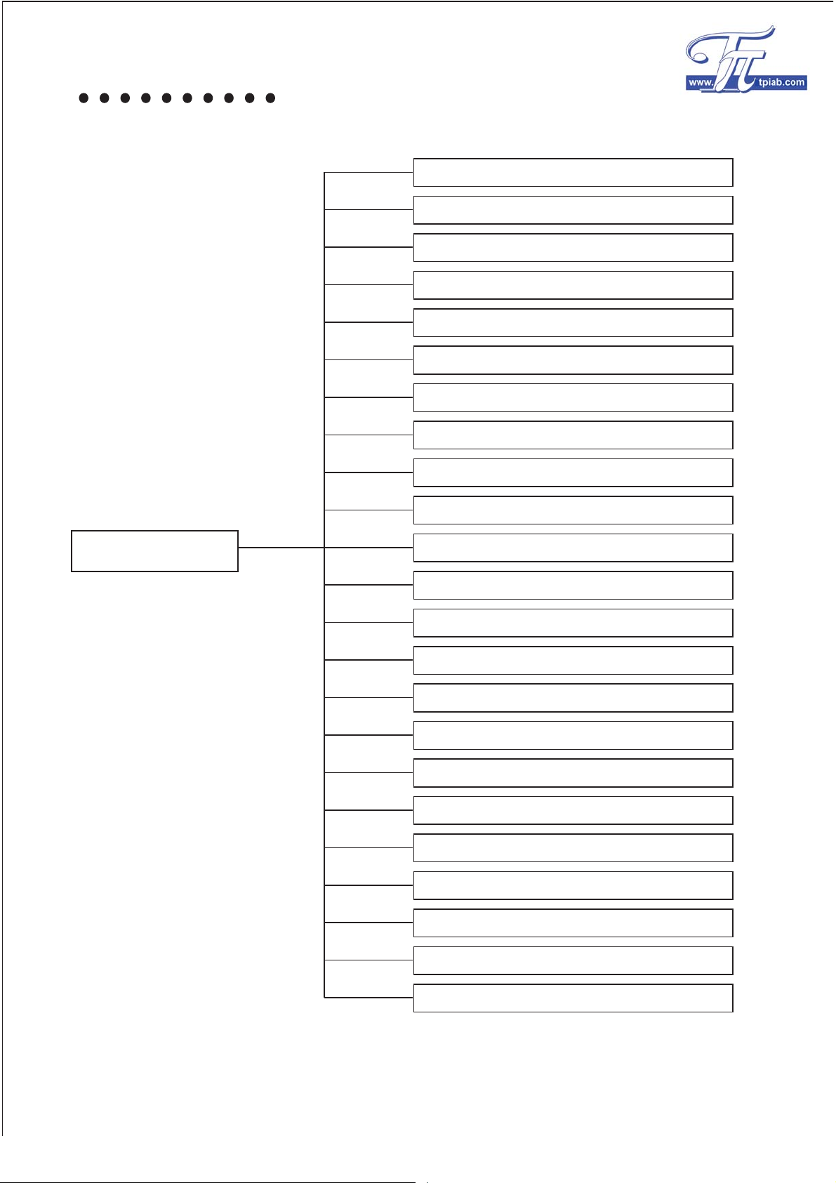
Main function
Cooling
Heating
Soft/dry
Auto operation
Temporary operation
Add and reclaim fluorine running
Sleep
24-hour timer
Vertical air direction adjustment
Main function
Vertical air direction adjustment
Capacity adjust(Inverter
Ice avoid(cooling model)
Cold air avoid(heating model)
Auto defrost
Heating overload protection
Cooling
Current
Discharge temp protection
Compressor 3-minute protection
IPM
overload protection
protection
protection
Low voltage protection
Frequency control
Faults & self-diagnoses
70
Page 8
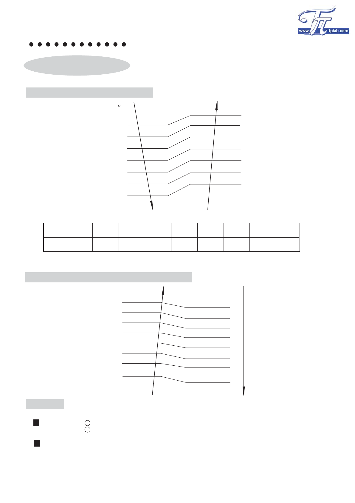
System control
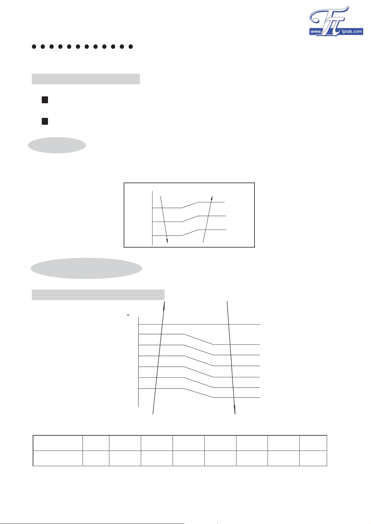
Cooling operation
Frequency control by indoor temp
C
3.5
3.0
2.5
Indoor temp-setting temp
2.0
1.5
1.0
0.5
0.0
A
B
C
D
E
F
G
H
Temp range
Frequency(Hz)
ABCDE FGH
89 85 81 77 73 37 28 0
Limit of the most frequency by outdoor temp
45
44
41
40
37
36
30
29
24
23
18
17
12
11
0
-1
Compress OFF
Fmax= 55Hz
Fmax= 73Hz
Fmax= 81Hz
Fmax= 89Hz
Fmax= 81Hz
Fmax= 73Hz
Fmax= 55Hz
Fmax= 46Hz
Ice avoid
Inlet condition: evaporator temp downİ2ć,system is running on the lowest frequency(28Hz).
evaporator temp down˘0ć,compressor OFF.
Return condition:evaporator temp raiseı6ć and continuous 10 minutes,the frequency rise
to the most.
1
2
71
Page 9
System control
Cooling
overload protection
Inlet condition: condenser temp raiseı58ć,system is running on the lowest
frequency(28Hz).
condenser temp raiseı62ć,compressor OFF.
Return condition:condenser temp down˘54ć and continuous 10 minutes when condenser down <52ć,
the frequency rise to the most.
O
1
O
2
Soft/dry
Automatically choose running frequency according to the numerical value between room
temp and setting temp.(CMOS chip enact the temp to 24ć).
Indoor temp-setting temp˄24ć˅
3.5
3.0
2.5
2.0
1.5
1.0
55Hz
46Hz
37Hz
28Hz
Heating operation
Frequency control by indoor temp
C
-0.0
-0.5
-1.0
-1.5
-2.0
-2.5
-3.0
-3.5
Temp range
A BC D E FGH
Indoor temp-setting temp
H
G
F
E
D
C
B
A
Frequency(Hz)
95 90 85 78 70 38 30 0
72
Page 10

System control
Limit of the most frequency by outdoor temp
ć
33
31
27
26
22
21
18
17
14
13
10
9
F
F
F
F
F
F
F
max
max
max
max
max
max
max
=0Hz
=46Hz
=54Hz
=62Hz
=78Hz
=90Hz
=95Hz
Heating
overload protection
Inlet condition: evaporator temp raiseı55ć,system is running on the lowest frequency(30Hz).
evaporator temp raiseı62ć,compressor OFF.
Return condition:evaporator temp down˘47ć and continuous 10 minutes,the frequency rise
to the most.
Cold air avoid
1
2
evaporator
temp
37ć
35ć
33
ć
ć
18
15
ć
low speed
Setting speed
UL speed
Fan stop
73
Page 11

System control
Auto defrost
Inlet condition: (only meet one condition)
1
Condenser temp İ3ćcontinuous40min,and Condenser temp İ-6ćcontinuous more 3minDŽ
tempć
3
-6
ı40min ı3min
2
Condenser tempİ3ć continuous80min ,and Condenser tempİ-4ćcontinuousPRUH3min.
tempć
3
-4
ı80min ı3min
3
Condenser temp İ3ćcontinuous 120min ,and Condenser tempİ-3ćcontinuous more 3min.
tempć
3
-3
ı120min ı3min
Time
Time
Time
Return condition: (only meet one condition)
Condenser temp risingı15ć
1
2
Condenser temp risingı8ćand continuous more 80S.
3
Defrost continuous 10min
Defrost action
Max10min
10s
Compressor
4-way valve
Outdoor fan motor
Indoor fan motor
ON 78Hz
30s
46Hz
ON
ON
ON
ON
OFF
OFF
OFF
30s 20s
OFF
ON
ON
ON
ON
74
Page 12

System control
Auto operation
Once enter into auto operation model,the unit automatically choose one running model among
cooling, single blowing,heating according to the numerical value between room temp(TA) and
setting temp(TS).First enter into auto model,the CMOS chip enact automatically to 24ć
Sleep
Cooling
TA-TS˚1ć
ˉ1ćİTA-TSİˇ1ć
TA-TSİˉ1ć
Room temp
Sleep function start
0-1 hour
About +1ć
About +1ć
3 hours
cooling
single blowing
heating
Stop operation
after 8 hours
Time
Heating
Room temp
Sleep function start
0-1 hour
About -2ć
3 hours
Stop operation
after 8 hours
About -2ć
Time
Temperary operation
If there is a fault with the remote controller or you lose it,you can operate it by this function.
Press the temperary switch for more 0.5s,the unit will enter auto operation model.
75
Page 13

System control
Protection functions
Discharge temp protection
When discharge temp 105ć˘td˘115ć,the system limit the frequency to 30HzDŽ
When
discharge temp td˘95ć and continue 10 minutes,rescind the protection.
When
discharge temp td˚115ć,compressor OFF and compressor restart until td˘95ć.
115ć
Discharge temp
105ć
95ć
ON
Compressor
OFF
30Hz 30Hz
3-minute waiting
It should wait 3 minutes when we restart the compressor.
Compressor
OFFON
3min
Low voltage protection
Heating
ON OFF
3min
30Hz
ON
106Hz
73Hz
65Hz
45Hz
30Hz
0
158 160 162 168 170 172 178 180 182 185 190
v
76
Page 14

System control
Cooling
98Hz
73Hz
65Hz
45Hz
30Hz
0
Current
When current of outdoor Idown˘Ict˘Istop,the system reduce the frequency by 1Hz/s until Ict˘IdownDŽ
When Inorm˘Ict˘Idown,prohibit compressor frequency to rise and can raise until Ict˘Inorm.
When current of outdoor Ict˚Istop,compressor off.
IPM
When there is 3 times IPM protection within 30 minutes,it means IPM fault,compressor off.
protection
ICT
Cooling˄A˅
Heating˄A˅
protection
158 160 162 168 170 172 178 180 182 185 190
stop Idown
I
12.0 10.5
14.0 12.0
?I
10.5
norm
7.5
v
77
Page 15

Wiring diagram
Indoor circuit
Indoor FAN motor
Outdoor circuit
Stepping motor
CN307
CN312
&1
&1
RY301
CN306
Brown
White
?Orange
CN305
CN302
1234
Indoor pipe thermo
1L NPE
CN314
Blue
Brown
CN304
Indoor air thermo
Yellow/green
PE
N
L
2XWGRRU
3RZHU
Display and Receptor board
W
V
U
-
+
Capacitor
Only cooling:
No 4-way Reversing valve
Black
CN13
CN12
CN11
CN10
CN09
DC Inverter
Compressor
White
Red
CN08 CN02
IPDU
Reactor
&RPSUHVVRU
FDVHWKHUPR
15
CN06
CN01
CN500
CN07
?Brown
Blue
CN12
CN11
CN14
CN5
1
5
N'
FAN
Outdoor air thermo
Yellow/green
L'
CN4
CDB
CN10CN9
?Outdoor pipe thermo
4-way Reversing
Valve
CN3
CN15
CN2
Orange
?Brown
Blue
N
CN7
L
CN1
1L N
Indoor
78
Page 16

Wiring diagram
Main parts list
name of parts
Remote controller"
Fan motor capacitor
Room temp. sensor
Indoor coil sensor
Compressor(R410A)
Compressor(R407C)
Fan motor
˄PG˅
Step motor
Relay
Power wire
Micro computer
Fuse
4-way valve
Fan motor
models
9000Btu 12000Btu
Indoor unit
cooling & heating cooling & heating
220V/50HZ 0.23A 16W 220V/50HZ 0.23A 16W
1.2F/450V 1.2F/450V
25BYJ48-Bˈ12VDC 300
JQX-102F-012 JQX-102F-012
12VDC,20A 250VAC
CBB61,1.2F/450V CBB61,1.2F/450V
3h1.0mm /10A
R25=5.0K¡ , B25/50=3950K R25=5.0K¡ , B25/50=3950K
R50=20.92K¡ , B0/50=3877K R50=20.92K¡ , B0/50=3877K
B25/50=3950K B25/50=3950K
TMP87PH46N TMP87PH46N
T3.15A/250V T3.15A/250V
2
¡
25BYJ48-Bˈ12VDC 300
12VDC,20A 250VAC?
3h1.5mm /16A
2
Outdoor unit
DA89X1F-22FD
Winding resistance:0.88¡(20ć)
DHF-5 ?DHF-9
KF20-6M ,20W,6P ,0.32A
220V/50HZ , 2F /450V 220V/50HZ , 2F /450V
Temp protector inside
˖OFF:125ć
ON: 95ć ON: 95ć
DA89X1F-22FD
DA89X1F-22FDDA89X1F-22FD
Winding resistance:0.88¡(20ć)
KF20-6M ,20W,6P ,0.32A
Temp protector inside˖OFF:125ć
¡
)DQPRWRUFDSDFLWRU
&RPSUHVVRU
FDVHWKHUPR
?Outdoor pipe thermo
?Outdoor air thermo
Current protector(CT) 25A ?25A
Micro computer
IPM
Electrolytic capacitor
TMP87P809Nǃ
Reactor
Fuse
Cooling capillary
Heating capillary
2F /450V 2F /450V
R95=4.1877K¡ R95=4.1877K¡
R110=2.6325K¡ R110=2.6325K¡
R115=2.2734K¡
B95/115=4365K B95/115=4365K
R0=15.0K¡ ,R25=5.286K¡
B0/100=3450K
R0=15.0K¡ ,R25=5.286K¡ R0=15.0K¡ ,R25=5.286K¡
B25/50=3450K B25/50=3450K
TMP88PH47N
2S16DAI
400VAC 50/60HZ 1500F
19mH 23/10A
T20A 250V T20A 250V
3.0h1.5h600
3.0h1.4h630
R115=2.2734K¡
R0=15.0K¡ ,R25=5.286K¡
B0/100=3450K
TMP87P809Nǃ
2S16DAI
400VAC 50/60HZ 1500F
19mH 23/10A
3.0h1.6h700
3.0h1.5h750
TMP88PH47N
79
Page 17

Page 18

Page 19

Page 20

Faults & self-diagnoses
Faults and solution
No Main reasons
Faults content
Wire connecting plate broken
1
or jointing copper foil open
AC open circuit
The transformer broken
Can't adjust the indoor fan
Can't adjust the
indoor fan speed
2
speed under sleeping mode
(low speed)
Can't adjust the indoor fan
speed under dehumidifying
mode (low speed)
Battery power used up
Wrong battery connection
Caused by other light
(too near)
Use the remote control with
3
Remote control signal
transmitting or
receiving error
incorrect place or angle
Broken wire connecting
Signal receiver error
PCB of remote control error
Chip wrong action
?Diagnose Normal conditions Solution
Check by eyes
Connecting plate and copper
foil connected well
Check voltage of the
AC10~16V
transformer
Check if the units under
sleeping mode
Check the operation mode
The speed changeable except
sleeping mode
The speed changeable
except dehumidifying mode
Check the voltage of battery
Check the direction of battery
Check after turning off the light
Use the remote control within
the valid angle and distance
Check the wire connection
Check the signal receiver
Check the weld of signal
The total voltage should > 2.5V
Instruction in the battery box
The unit recover after turning
off the light
Signal transmits OK within
the valid angle and distance
No connection broken
Steady connection,touch well
No rupture and weld ill
receiver
Check the remote controller
Replace the signal receiver
and check it
Use temporary switch for
Remote controller transmit well
Signal receive successfully
The unit operate well
test
Try again after turning off
the power
The unit start to run after
restart
Chang the connecting plate or
repair the jointing copper foi
Change the transformer
Explain to user
Explain to user
Change the battery
Correct the direction of battery
Change the location of the light
Use the remote control
according to the User Manual
Change the connecting wire
Repair and correct the
connection
Change the signal receiver
Change the remote controller
Change the signal receiver
Change the PCB of remote
control
Anti-jamming to the chip
Solution to disturbance
4
The horizontal grill
action error
The compressor don't
start
5
Linkage construction fall off
The joint ends of the
horizontal grill fall off
Step motor error
Wrong wire connection
(Communication error)
IPM protection or default
Check the linkage parts
Check both ends of the
horizontal grill plate
Check the existence of
step motor
Check the wire connection
Turn off the power, discharge
the power of capacitor and
then test the current.
Check the heat sinker of the
IPM
The horizontal grill move easy
Both ends of horizontal grill
plate steady installation
1-3
1-2
575¡
1-4 1-5
575¡ 575¡ 285¡
L-N˖AC220V
1-N˖Being lined signals
Running: DC 2.5V
Stop: DC 12-18V
Overload current DC<2.5A
normal
data
Ğ
normal
data
Ğ
Test data
N
U
P
V
W
Test data
U
V
W
N
normal
data
530K
420K
normal
data
420K
Test data
N
U
P
V
W
Test data
U
V
W
N
Heat disperse well
Repair the linkage parts?
Confirm the joint ends well
connected
Change the step motor
Correct the wire connection
Change the IPM
Change the heat sinker
82
Page 21

Faults & self-diagnoses
No Main reasons "Diagnose
5
Faults content
Compressor don't
move
Electro-analysis capacitor
error
The fuse of the outdoor unit
broken
The compressor block
The compressor burnt
Commutating bridge error
Turn off the power, discharge
the power of capacitor and
then check it if there is
broken or transfiguration
Check by the current meter
Check the resistance by
the current meter
Check the 20A fuse
Turn on the power and
confirm the start
The compressor shake and
stop.
Check the existence R-S
R-C and S-C
Turn off the power, discharge
the power of capacitor and
then check the existence
Normal conditions Solution
No broken and transfiguration
Positive and negotive meter
pole connected with capacitor
terminals,multimeter needle
rotate completely,and then
slowly revent,change polavity,
the same result(while
oppositive polavity checked,
first discharging)
R=0 OK
R= Broken
Ğ
Can start
BH108/BG108˖1.18¡
BH103/BG130˖1.33¡
Test data
+
~
-
Test data
-
~
-
normal
data
-
+
Ğ
~
normal
data
+
+
10K¡
~
Change the electro-analysis
capacitor
Change fuse
Change compressor
Change compressor
Change the commutate
bridge
6
7
Indoor fan don't
move
Outdoor fan don't
move
Inductance error
Connecting broken
Burnt
Coil of the motor burnt
The temp sensor of indoor
coil open wire (when heating
operation)
Feed back error
Fan capacitor error
Connecting wire broken
Fan capacitor error
Relay error
Coil burnt
Check the resistance of the
inductance
Check it by eyes
Check it by the current meter
Test the resistance of 1-2
Check it by the current meter
Confirm by charge and
discharge of the capacitor
Check by eyes?
Confirm by charge and
discharge of the capacitor
Check by the current meter
Check by the current meter Change the motor
About 0.2 ohm
Steady connection
1~2
1~3 2~3
1010¡ 526¡ 485¡
20ć 25ć 30ć 35ć 40ć
7.3K¡ 5.8K¡ 4.7K¡ 3.8K¡ 3.1K¡
1~2 1~3 2~3
15.8K¡
16K¡
(positive)
(positive)
19K¡
(negotive)
17.1K¡
(negotive)
Steady connection
Same as Electro analysis
capacitor
No short circuit and open circuit
1~3 1~9 3~9
158¡
240¡
8.7K¡
(positive)
8.9K¡
(negotive)
392¡
Change the inductance
Repair and correct the
connection
Change the motor
Change the sensor
Change the motor
Change the capacitorSame as above
Repair and correct the
connection
Change the capacitor
Change the relay
83
Page 22

Faults & self-diagnoses
No
8
9
10
11
Faults content
4-way valve
don't work
(heating mode)
Abnormal high temp with
the compressor
Indoor temp sensor error
Outdoor temp sensor fault
Main reasons "Diagnose Normal conditions Solution
Connect wire broken
Coil short circuit or open
circuit
Insulation ageing
The valve can not move
Air inlet or outlet block
with the outdoor unit.
Refrigerant leakage
Discharge temp sensor error
Indoor heat exchanger sensor
error
Resistance abnormal Short
circuit or open circuit
Resistance abnormal Short
circuit or open circuit
Check by eyes or hands
Check the resistance
DC 500V insulation ageing
test
Don't heating after frequency
rise
Check by eye
Check the leakage
Resistance test 1-2
Resistance test 1-2
Resistance test 3-4
Resistance test 1-2
Connect OK
13K ohm between 1-3
>1000M ohm
can change normally
No block with Air in and out
No leakage
25ć20ć
25ć20ć
25ć20ć
25ć20ć
30ć 35ć
46.1K¡57.5K¡71.5K¡
30ć 35ć
30ć 35ć
30ć 35ć
37.2K¡
3.8K¡4.7K¡5.8K¡7.3K¡
3.3K¡4.0K¡5.0K¡5.3K¡
3.6K¡4.4K¡5.3K¡6.4K¡
40ć
30.2K¡
40ć
3.1K¡
40ć
2.7K¡
40ć
3.0K¡
Correct the connection
Change the coil
Change the coil
Change the valve
Confirm the air inlet and outlet
Fill in refrigerant
Change the discharge temp
sensor
Change the indoor exchanger
sensor
Change the indoor temp
sensor
Change the outdoor temp
sensor
Outdoor heat exchange
12
sensor error
Current inductance error
13
Voltage inductance error
14
Resistance abnormal Short
circuit or open circuit
Resistance broken
Current inductance fault
Resistance broken
Voltage inductance fault
Resistance test 1-2
Check the resistance
Creepage check to the
capacitor
Check the resistanc
Check the capacitance
leakage
30ć 35ć
25ć20ć
No open-circuit
Normal charge and discharge
with the capacitor
No open-circuit
Normal charge and discharge
with the capacitor
40ć
3.0K¡
3.6K¡4.4K¡5.3K¡6.4K¡
Change the outdoor heat
exchange sensor
Repair the resistance
Change the current
inductance
Repair the resistance
Change the voltage
inductance
84
Page 23

Service Parts List
Indoor Unit
REF.NO
Parts Name
Fan motor
1
Remote controller
2
Control board ass'y
3
Control board
4
Receiving & Indicator board
5
Power wire
6
Terminal (4P)
7
9000Btu
(heat pump)
Electrical Parts
AAQ022123002
ABK260234202
ABK251326100
ABK251326101
AAK161328102
AAX161328002
AAU161328002
R410A
Parts No
Q'TY Q'TY
1
1
1
1
1
1
1
12000Btu
heat pump
AAQ022123002
ABK260234202
ABK251334100
ABK251334101
AAK161328102
AAX161328002
AAU161328002
1
1
1
1
1
1
1
8
Temp.sensor indoor
9
Evaporator temp.sensor
10
Step motor
11
Installation plate
12
Air-outlet ass'y
13
Motion link
14
Horizontal eliminating vane A
15
Horizontal eliminating vane B
16
17
Vertical eliminating vane
18
Drain plug
Drain hose
19
Front panel
20
AAD161328010
AAD161328010
AAQ160245003
Construct Parts
AAE160245001
ABC260234101
AAC140226126
AAC140226124
AAC140226125
AAC140226123
AAC140226134
AAF260235019
AAC140226101
12
1
1
1
1
1
1
2
2
2
1
1
1
AAD161328010
AAD161328010
AAQ022123002
AAE160245001
ABC260234101
AAC140226126
AAC140226124
AAC140226125
AAC140226123
AAC140226134
AAF260235019
AAC140226101
1
1
1
1
1
1
2
12
2
2
1
1
1
21
Front frame
AAC140226105
1
AAC140226105
1
85
Page 24

Service Parts List
Indoor Unit
REF.NO
Parts Name
Nail lid
22
Indicator signal cover
23
Indicator signal
24
Basing ass'y
25
Air filter
26
Bearing asss'y
28
29
Cross flow fan
30
Control box
bracket
9000Btu
only cooling
Parts No
Q'TY Q'TY
9000Btu
heat pump
AAC140226106
AAC140226103
AAC140226104
AAC140226108
AAC140226107
AAC140226135
AAY160245002
AAC140226115
2
1
1
1
2
1
1
1
12000Btu
only cooling
R410A
12000Btu
Q'TY
heat pump
AAC140226106
AAC140226103
AAC140226104
AAC140226108
AAC140226107
AAC140226135
AAY160245002
AAC140226115
Q'TY
2
1
1
1
2
1
1
1
Receiving and indicating board bracket
31
32
Sensor bracket
Distribution tubing fixed plate
35
Motor fixed plate
38
Evaporator induced tube ass'y
39
40
Evaporator ass'y
AAC140226120
AAC140226136
AAC140226112 AAC140226112
AAC140226114 AAC140226114
1
1
AAC140226120
AAC140226136
1
1
Cycle parts
AAB140226100
AAN260226100
1
1
AAB140226100
AAN260235100
Printing parts
1
1
1
1
1
1
44
45
46
Name plate
Wiring diagram
Inventer sign
ABT251326005 ABT251334005
ABL260234002
AAI161328015
1
1
1
ABL260234002
AAI161328015
86
1
1
1
Page 25

Service Parts List
Outdoor Unit
REF.NO
Parts Name
Fan motor
1
IPDU basing board ass'y
2
Control basing board ass'y
5
Discharge temp.sensor
7
Temp.sensor outdoor heater exchanger
8
9000Btu
only cooling
R410A
Parts No
9000Btu
Q'TY Q'TY Q'TY Q'TY
heat pump
Electrical Parts
ABQ251334001
AAK161328105
AAK161328104
AAD161328003
AAD161328014
12000Btu
only cooling
1
1
1
1
1
12000Btu
heat pump
ABQ251334001
AAK161328105
AAK161328104
AAD161328003
AAD161328014
1
1
1
1
1
9
Ambient air Temp.sensor outdoor
Terminal (4P)
10
Compressor wire
12
Electrolytic capacitor
14
4-way valve coil
16
Reator
17
Base ass'y
18
Base seal A
19
Base seal B
20
Compressor bottom cover
21
AAD161328013
AAU161328001
AAX161328012
AAR161328001
AAB162145301 AAB162145301
AAD161328001 AAD161328001
Construct Parts
AAE251334500
AAF160245401
AAF160245402
AAF141226101
1
1
1
1
AAD161328013
AAU161328001
AAX161328012
AAR161328001
1
1
1
1
5
1
AAE251334500
AAF160245401
AAF160245402
AAF141226101
1
1
1
1
1
1
1
1
5
1
88
Page 26

Service Parts List
Outdoor Unit
REF.NO
Parts Name
Compressor damping rubber
22
Valve base
23
Valve bolt
24
Compressor damping pad
25
Compressor damping nut
26
27
Motor angle
Motor angle seal A
28
Motor angle seal B
29
Propeller fan
30
9000Btu
only cooling
R410A
Parts No
Q'TY Q'TY Q'TY Q'TY
9000Btu
heat pump
ABG251334002
AAE160245102
AAG150270001
AAG022123020
AAG160245003
AAE251326502
AAF141226406
AAF141226407
AAY160245001
12000Btu
only cooling
3
1
4
3
3
1
1
1
1
12000Btu
heat pump
ABG251334002
AAE160245102
AAG150270001
AAG022123020
AAG160245003
AAE251326502
AAF141226406
AAF141226407
AAY160245001
3
1
4
3
3
1
1
1
1
Fan fixed nut
31
Bulkhead
32
Sound proof cover A
34
35
Sound proof cover B
Compressor top cover
36
Control box
37
IPDU bracket
38
Heat sinker
39
Bulkhead seal A
40
Bulkhead seal B
41
Condenser seal
44
AAG022123018
AAE130226106
AAF141226103
AAF141226104
AAF141226102
AAE161328109
AAE161328125
AAD161328005
AAF161328403
AAF161328404
AAF161328405
1
1
1
1
1
1
1
1
1
1
1
AAG022123018
AAE130226106
AAF141226103
AAF141226104
AAF141226102
AAE161328109
AAE161328125
AAD161328005
AAF161328403
AAF161328404
AAF161328405
1
1
1
1
1
1
1
1
1
1
1
Right side plate
45
AAE260235503
1
AAE260235503
1
89
Page 27

Service Parts List
Outdoor Unit
REF.NO
Parts Name
Right side plate seal A
46
Right side plate seal B
47
Wire fixed board
49
Front panel
50
Fan guard
51
Handle
52
Temp.sensor bracket outdoor
53
Air-inlet grill
54
Covering plate
55
9000Btu
only cooling
R410A
Parts No
9000Btu
Q'TY Q'TY Q'TY Q'TY
heat pump
AAF141226409
AAF141226410
AAE160245107
AAE160245101
AAC160245203 AAC160245203
AAC160245205
AAC161328201
AAC160245204
AAE160245104
12000Btu
only cooling
1
1
1
1
12000Btu
heat pump
AAF141226409
AAF141226410
AAE160245107
AAE160245101
1
1
1
1
11
1
1
1
1
AAC160245205
AAC161328201
AAC160245204
AAE160245104
1
1
1
1
Control box cover
56
Compressor ass'y
57
Terminal cover
58
Terminal cover gasket
59
Terminal cover nut
60
61
Ruber-washer
Condenser ass'y
62
4-way valve ass'y
63
Capillary tube ass'y
64
65
2 - way valve(7/16'')
3 - way valve(5/8'')
66
3 - way valve(3/4'')
67
7/16'' nut
68
Dž
5/8 nut
69
AAC161328201
Cycle parts
ABP251334001
AAF141226102
AAF141226101
AAG022123016
AAG022123024
AAN251334200
ABB251334300
AAM161326001
ABZ251326703
ABZ251326704
AAB022123802
AAB022123702
1
1
1
1
1
1
1
1
1
1
AAC161328201
ABP251334001
AAF141226102
AAF141226101
AAG022123016
AAG022123024
AAN251334200
ABB251334300
AAM161328001
ABZ251326703
1
0
1
ABZ251334704
AAB022123802
1
1
1
1
1
1
1
1
1
1
1
0
1
1
0
90
Page 28

Service Parts List
Outdoor Unit
REF.NO
Parts Name
Valve top (big)
72
Drain plug
74
75
Capacitor fixed clip
Name plate
76
Wiring diagram
77
9000Btu
only cooling
R410A
Parts No
9000Btu
Q'TY Q'TY Q'TY Q'TY
heat pump
AAB160245702
1
ABF260234001
01
1
AAE160245108
Printing parts
ABT251326006 ABT251334006
1
ABL161328004
1
12000Btu
only cooling
11
11
1
1
12000Btu
heat pump
AAB160245702
ABF260234001
01
AAE160245108
1
ABL161328004
1
1
1
1
1
78
Inventer label
1
ABT251334018
1
1
ABT251334018
1
91
 Loading...