


TASKMASTER
5100 SERIES
Horizontal or Vertical Mounting
Industrial / Commercial
NOT FOR RESIDENTIAL USE
INSTALLATION
INSTRUCTIONS
& PARTS LIST
Unit Heater
ATTENTION: Read carefully before
attempting to install, operate or service
the TaskMaster Unit Heater. Retain these
installation instructions for future use.
PRODUCT FEATURES
• Forced air electric unit heater available in 208,
240/208, 227, 480, 550 or 600 volt as standard.
• Ten standard heating capacities of 3.3 KW/11,260
BTUH thru 50.0 KW/170, 600 BTUH.
• 208 and 240/208 volt models are single phase eld
convertible to three phase on 3.3 thru 10.0 KW
Models. (Single phase only available on 3.3, 5.0, 7.5
and 10 KW 277 volt models.
• Specially designed inlet louver allows the fan to pull
cool air evenly across the high mass all-steel element.
• Outward drawn venturi and adjustable louver
assembly further directs the outlet air in a uniform
pattern to meet specic air pattern requirements in
either the horizontal or vertical mounting position.
• Optional wall/ceiling or vertical mounting brackets (as
required).
• Four position weld nuts supplied in case top and back
for eld mounting by threaded rods or eye bolt with
chain. (Hardware supplied by others).
• Optional radial or anemostat diusers lending air
pattern versatility when mounted vertically.
• Modular control kits for eld installation. Disconnect
switch, thermostat, summer fan switch, heat recovery
thermostat. All kits with spade terminals (Except
• disconnect switch).
• Single point terminal board wiring of integral control
kits.
• 24 volt low voltage control circuit standard on all
contactor and transformer models.
• Roomy control box with access door locked into
position by two (2) 1/4 turn fasteners for ease of
installation.
IMPORTANT: OWNER SHOULD RETAIN THESE INSTRUCTIONS FOR FUTURE REFERENCE
1 of 20
ECO 1-7874
REV. 10/22
FORM: 9632

IMPORTANT INSTRUCTIONS
When using electrical appliances, basic precautions should always be followed to reduce the risk of re, electrical shock,
and injury to persons, including the following:
1. Read all instructions before using this heater.
2. CAUTION:
ATTENTION:
High temperatures. Keep cords and all other combustible material, such as furniture, papers, clothes
and curtains away from the heater. For safe and ecient operation, keep an open space around
heater of three feet in front and 12 inches at ends and rear.
Les températures élevées. Gardez les cordons et tout autre matériau combustible, tels que les
meubles, papiers, vêtements et rideaux à l’extérieur de l’appareil de chauage. Pour un
fonctionnement sûr et ecace, garder un espace ouvert autour de chauage de trois pieds à l’avant et
12 pouces aux extrémités et à l’arrière.
3. Extreme caution is necessary when any heater is used by or near children or invalids and whenever the heater is left
operating and unattended.
4. Do not operate any heater after it malfunctions, has been dropped or damaged in any manner. Return heater to
authorized service facility for examination, electrical or mechanical adjustment, or repair.
5. Do not use outdoors.
6. To disconnect heater, turn controls to o, and turn o power to heater circuit at main disconnect panel (or operate
internal disconnect switch if provided).
7. Do not insert or allow foreign objects to enter any ventilation or exhaust opening as this may cause an electric chock
or re, or damage the heater.
8. To prevent a possible re, do not block air intakes or exhaust in any manner.
9. A heater has hot and arcing or sparking parts inside. WARNING: Do not use it in area where gasoline, paint, or
ammable liquids are used or stored.
10. Use this heater only as described in this manual. Any other use not recommended by the manufacturer may cause re,
electric shock, or injury to persons.
11. This heater may include an audible or visual alarm to warn that parts of the heater are getting excessively, hot. If the
alarm sounds (or illuminates), immediately turn the heater o and inspect for any objects on or adjacent to the heater
that may have blocked the airow or otherwise caused high temperatures to have occurred.
DO NOT OPERATE THE HEATER WITH THE ALARM SOUNDING (OR ILLUMINATING)
12. SAVE THESE INSTRUCTIONS
Maintenance:
Caution: Make certain that the power source is disconnected before attempting to service or disassemble any component. If the power
disconnect is out of the line of sight, lock it in the OPEN position and tag to prevent the application of power. Make sure the heater has
cooled enough to safely handle.
Electrical:
Once a year inspect the control panel wiring to make certain insulation is intact and all connections are tight. Inspect all heater and relay
contacts. If the contacts appear badly pitted or burned, replace the contactor/relay.
Cleaning:
Clean the unit casing, fan and motor once a year. A dirty motor will tend to run hot and eventually will be damage internally. Use the
crevice tool on a vacuum cleaner or a clean cloth to clear dust and dirt. Any rust spots on the casing should be cleaned and repainted.
Lubrication:
All units have fan motors that are permanently lubricated so that only occasional cleaning is required.
2 of 20
ECO 1-7874
REV. 10/22
FORM: 9632

PROPER LOCATION INSTRUCTIONS
GENERAL SAFETY INFORMATION / CAUTION:
Once the total heating load is calculated, the quantity and
capacity of the unit heaters must be determined. because a
large number of low-capacity heaters provides more uniform
heat distribution. This approach is recommended when
the area will be occupied by a relatively large number of
sedentary personnel, (i.e. working on production lines and
at benches.)
A large number of smaller capacity unit heaters tends to
prevent hot drafts, reduces noise levels, and increases
diversity of load to help reduce electrical demand and
operating costs.
In warehouses where even heat distribution and constant
temperatures are less important, a smaller number of high
capacity units can be used -- in many cases reducing
installation cost. To maintain reasonable heat distribution
and reduce severe stratication even in lower bay areas, the
total air volume of the space should pass through the unit
heaters about three times per hour. (Take total cubic feet
and divide by 20 in order to determine proper total heater
CFM rating.)
It is important that the rated voltage of the heating equipment
match the supply voltage. Supply voltage in excess of the
heater rated voltage can damage equipment. Supply voltage
lower than the rated heater voltage will decrease heater
output as well as run the risk of damaging some components.
Horizontal unit heaters are recommended in low bay areas
with maximum 15 to 18 foot ceilings. These should be
concentrated along outside wall or other areas of greatest
heat loss; spaced to set up a generally circular air movement,
each heater supporting the air stream of the other. Additional
vertical down below unit heaters with appropriate accessory
diusers can be located to counteract ceiling heat losses
(see Figure 1 Location charts).
Figure 1
Follow all local electrical and safety codes, as well as the
National Electrical Code (NEC) and the Occupational Safety
and Health Act (OSHA).
To avoid possible electrical shock, be sure the electrical
current is turned o at the main switch prior to wiring or
servicing of unit.
If the power disconnect is not integral and is out-of-sight,
lock it in the open position and tag to prevent unexpected
application of power prior to performing any service or
maintenance of the unit.
The unit when installed must be electrically grounded in
accordance with the National Electrical Code and standard
industry practice.
Make certain that the power source conforms to the
requirements of your equipment. See Table 2 on page 6 for
wire and circuit size
Check heater voltage and phase on rating label to conrm
that it matches the electric service supply.
Wiring diagrams of the heater and supply connections are
permanently attached to the inside of the heater access
door. All terminals are coded in accordance with the wiring
diagram. Accessory wiring are shown on the unit wiring
diagram and supporting literature.
The heater must be mounted at least 7’ above the oor to
prevent accidental contact with the fan blade which could
cause injury. Install unit so there are no obstructions to the
intake or discharge. Maintain clearances as shown on Table
1, 2, Fig. 1 & 2.
The wall/ceiling mounting structure and anchoring provisions
must be on sucient strength to support the combined
weight of the heater and mounting bracket.
3 of 20
ECO 1-7874
REV. 10/22
FORM: 9632
PRINCIPLES OF OPERATION
Upon a call for heat from the oor level or unit mounted
optional accessory thermostat, the unit fan motor and
heating elements shall be energized and remain ON until
temperature reaches setting of thermostat; at which time the
heating elements shall be deenergized.
The fan motor shall continue to run and purge heater casing
of residual heat until setting of fan override is reached, then
the fan motor shall be deenergized.
For those units with a factory installed two speed fan switch
(25-50KW), the unit as shipped from the factory is set to
“low” speed. Customer option to set to “high” speed. For
those units available with subdivided circuits, the accessory
two stage thermostat (optional) will, upon a call for heat,
energize fan motor and the rst stage heating element.
Should temperature continue to fall, the thermostat shall
energize the second stage heating element.
Upon a rise in space conditions towards setting of the
thermostat, the two stages of heating elements shall be
deenergized in reverse sequence.
The fan motor shall continue to run and purge heater casing
of residual heat until setting of fan override is reached, then
the fan motor shall be deenergized.
The accessory unit mounted stratication thermostat
will energize the unit heater fan motor upon a rise in
temperature above its setting.
When the unit mounted stratication thermostat closes on a
temperature rise and at the same time the oor thermostat
calls for heat, the motor shall be energized immediately
and the heating element shall be energized, as previously
described.
The automatic reset safety high limit shall deenergize the
heating elements and control circuits should the temperature
exceed the setting of this device. The fan safety override
shall energize fan motor any time the setting of this device
is exceeded so as to purge heater casing of excess residual
heat.
When the accessory fan switch is placed in the ON position
(for summer air circulation), the unit heater fan motor shall
be energized.
NOTE: The wall thermostat is to be set to the OFF position
during this mode of operation (units with contactors).
For those accessory thermostats equipped with an integral
fan switch, place the switch in the HEAT, or AUTO position
for operation of the fan and elements which shall then be
under control of the thermostat as described above.
When switch is placed in the OFF position, the unit shall
be deenergized. When switch is placed in the FAN position,
elements shall be deenergized and fan shall be immediately
energized.
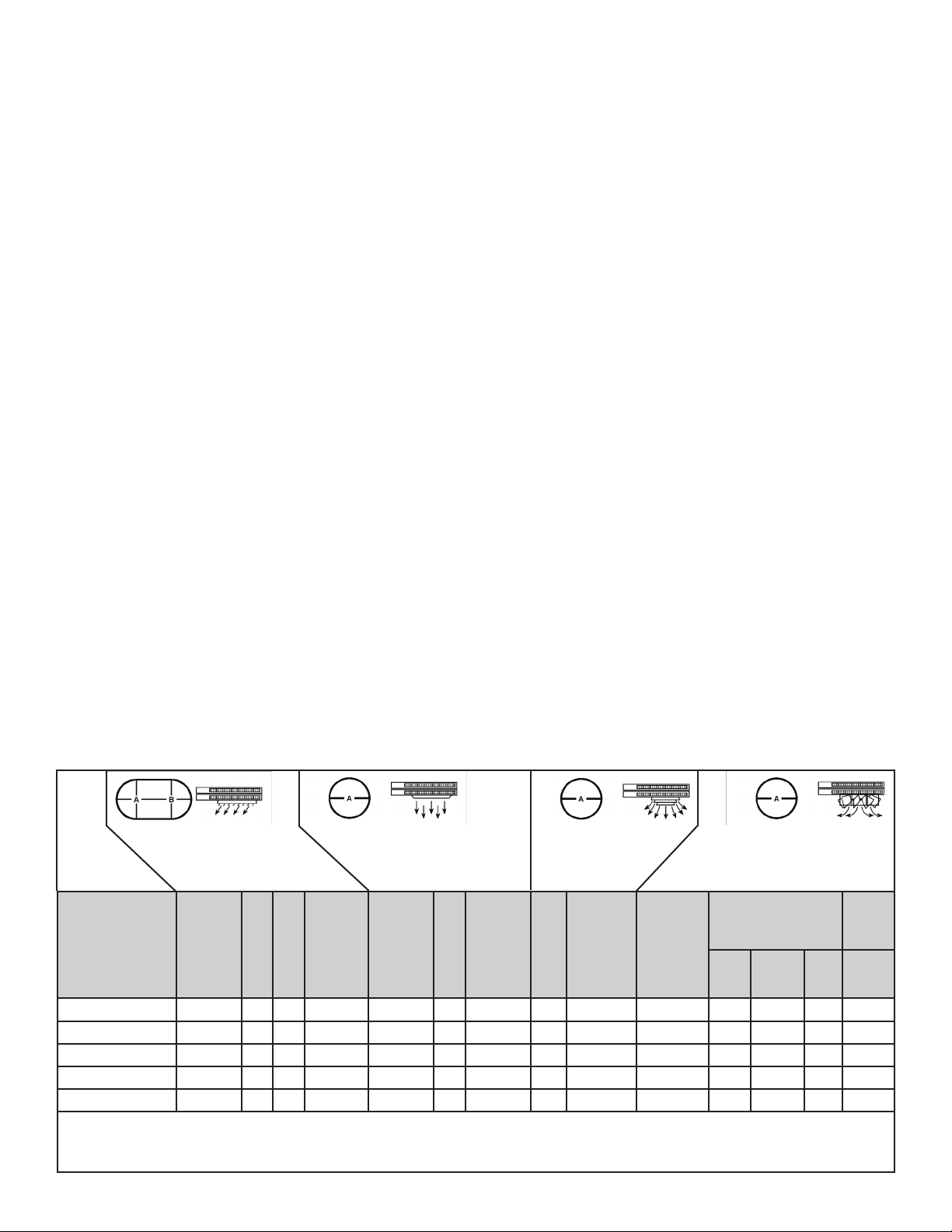
VERTICAL DISCHARGE UNITS - AIR PATTERNS
Louver Diuser (Standard) General Distribution
USED ON
3.3 & 5.0 Kw 9 20 10 STD 9 15 -- -- N/A N/A -- -- -- --
7.5 & 10.0 Kw 12 40 22 STD 12 30 10 30 AD5120 RD5120 0 14 36 30
15.0 & 20.0 Kw 18 52 30 STD 18 40 15 38 AD5120 RD5120 14 21 42 35
25.0 & 30.0 Kw 22 75 42 STD 22 55 17 50 AD5150 RD5150 20 30 62 44
40.0 & 50.0 Kw 24 84 47 STD 24 64 20 60 AD5150 RD5150 18 28 68 54
STD = Standard N/A = Not Applicable
Optional diusers lend added air pattern versatility to individual vertical down blow installations as shown in above illustrations.
MAX
MTG.
HEIGHT
A B
STOCK
NO.
(No Diuser)
MAX
MTG.
HEIGHT
A
4 of 20
MAX
MTG.
HEIGHT
Anemostat Diuser
(Optional)
STOCK
A
NO.
Radial Diuser (Optional)
MAX MTG. HEIGHT A
STOCK
NO.
45oOPEN 45oOPEN
ECO 1-7874
REV. 10/22
FORM: 9632

INSTALLATION INSTRUCTIONS
9/16" K.O.
*
For vertical discharge
mounting bracket
Diagrams not to scale
9/16" K.O.
1/2" K.O.
9/16" K.O.
(4) 5/16" K.O.
7.5 - 20 KW
1/2" - 3/4" K.O.
9/16" K.O.
1/2" K.O.
3/4" K.O.
3/4" - 1" K.O.
9/16" K.O.
(4) 5/16" K.O.
3.3 - 5.0 KW
TASKMASTER -- 5100 SERIES UNIT HEATER
ATTENTION: READ INSTRUCTION CAREFULLY
All electric unit heaters are shipped fully assembled. Installation includes
hanging the unit, mounting the built-in and remote accessories, wiring of
optional control devices, and electrical wiring to the unit.
To insure proper delivery of the heated air to desired areas, follow the
mounting height and air projection tables include in these instructions.
Follow Fig. 1 & 2 for minimum wall and ceiling clearances.
MOUN TI NG
CL EA RA NC E
12"
12"
12"
7'
12"
7'
Heaters may be mounted in the horizontal or vertical air discharge
conguration using factory optional supplied accessory mounting equipment
or using special hardware facilities supplied by others.
After the installation is complete, replace the access panel.
Set the controls (thermostat, switch) at their desired control point and apply
power to the unit.
Check correct operation.
DIMENSIONS
FI G. 1 FI G. 2
HO RI ZONT AL DIS CH AR GE VE RT IC AL D IS CH AR GE
The wall and/or ceiling structure must be sucient to support the combined
weight of the heater and any mounting bracket and accessories.
Be sure power source is deenergized before installing heater. Check heater
voltage and phase listed on heater date tape on back of unit to make sure
they are the same as the electrical service supplied.
Certain units are convertible from single to three phase service. Follow
instructions noted on the unit wiring diagram for this conversion. Units
that carry a dual voltage rating (HF) require specic wiring changes when
converting from 240 to 208 volt service supplied.
Open the access panel (2 1/4 turn fasteners).
Remove the desired knock-out(s) on back of the heater.
Install any optional accessories following their installation instructions
before mounting unit. Following the correct unit/accessory wiring diagram,
connect the power supply, electrical ground and accessories to the correct
terminals or termination points using accepted practices.
NET JUNCTION BOX VOLUME
Kw CUBIC INCHES CC
3.3-5 74.4 1219
7.5-10 19.8 3245
15.0-20 19.8 3245
25.0-50 34.1 5592
DIMENSIONS (INCHES)
Kw H W D
3.3-5.0 17-3/4 14-15/32 6-1/2
7.5-10 24-5/16 21-1/2 6-1/2
15.0-20 28-11/16 21-1/2 6-1/2
25.0-50 34 29-1/4 10-1/16
5 of 20
ECO 1-7874
REV. 10/22
FORM: 9632

INSTALLATION INSTRUCTIONS
B
A
TASKMASTER -- 5100 SERIES UNIT HEATER (part 2)
HORIZONTAL -- AIR DISCHARGE MOUNTING
SHOWN IN: FIGURE 5 & 6
Swivel hanger brackets may be used to suspend unit heaters from either
the wall (gure 5) or the ceiling (gure 6). Attach hanger base “A” to top of
heater with the four 5/16 X 18 caps screws and lockwashers (provided in
envelope).
Attach main hanger frame “B” to wall or ceiling in desired location using lag
screws “C” or other suitable attachments (supplied by others).
Lift heater into position inserting stud “D” through hole in main hanger frame
and attach lock nut “provided in envelope) “E” tightening to within two turns
of being tight.
Swivel heater to desired position, tighten lock nut.
VERTICAL -- AIR DISCHARGE MOUNTING
Figure 5
WALL MOUNT
HORIZONTAL DISCHARGE
E
D
SHOWN IN: FIGURE 7
Attach short angle brackets “A” to back of heater with four 5/16 X 18
capscrews “B”, lockwashers “F”. Be sure vertical leg of angle brackets face
top and bottom of heater.
Attach inverted U frames “D” to short angle brackets with four 5/16
X 18
capscrews “K”, washers “L”, lockwashers “M” and nuts “N”.
Attach long angle brackets “J” to inverted frames “D” with four 5/16
X 18
capscrews “K”, washers “L”, lockwashers “M” and nuts “N”.
Attach heater and bracket assembly to ceiling in desired location using
customer supplied equipment sucient to support the assembly.
Figure 7
CEILING MOUNT
VERTICAL DISCHARGE
J
K
L
Figure 6
CEILING MOUNT
HORIZONTAL DISCHARGE
M
N
D
C
B
C
E
D
A
F
B
F
A
NOTE: When mounting heater using 5/16” all thread rod (by others) do not
screw the rod more than 1/2” beyond the inside of the case.
6 of 20
ECO 1-7874
REV. 10/22
FORM: 9632

Catalog
Number
F1F5103
5103NF1F
F2F5103
5103NF2F
HF1B5103
5103NHF1B
HF2B5103
5103NHF2B
G1G5103
5103NG1G
P3P5103CA1
5103CA1NP3P
F1F5105
5105NF1F
F2F5105
5105NF2F
HF1B5105
5105NHF1B
HF2B5105
5105NHF2B
G1G5105
5105NG1G
P3P5105CA1
5105CA1NP3P
F2F5107CA1
5107CA1LF2F
HF2B5107CA1
5107CA1LHF2B
G1G5107CA1
5107CA1LG1G
P3P5107CA1
5107CA1NP3P
F2F5110CA1
5110CA1LF2F
HF2B5110CA1
5110CA1LHF2B
G1G5110CA1
5110CA1LG1G
P3P5110CA1
5110CA1NP3P
F3F5115CA1
5115CA1LF3F
HF3B5115CA1HF3B5115CA1
5115CA1LHF3B5115CA1LHF3B
P3P5115CA1
5115CA1NP3P
HF3B5120CA1HF3B5120CA1
5120CAILHF3B5120CAILHF3B
P3P5120CA1
5120CA1NP3P
F3F5125CA1
5125CA1LF3F
HF3B5125CA1HF3B5125CA1
5125CA1LHF3B5125CA1LHF3B
P3P5125CA1P3P5125CA1
5125CA1NP3P5125CA1NP3P
5100 SERIES UNIT HEATER ELECTRICAL DATA (Table 2)
Kw
BTU/HR
(000)
HEATER/MOTOR
VOLTAGE
HEATER
PHASE
CONTROL
VOLTAGE
AMPS
PER
PHASE
3.3 11.2 208 1 208 15.9 20 12
3.3 11.2 208
1
3
208
15.9
9.2
3.3/2.5 11.2/8.5 240/208 1 240/208 13.7/11.9 20/15 12/14
3.3/2.5 11.2/8.5 240/208
277
3.3 11.2
277
480
480
1
3
1
1
3
3
240/208
277
277
24
24
13.7/11.9
7.9/6.9
11.9
11.9
4.0
4.0
5.0 17.1 208 1 208 24.1 35 8
5.0
17.1
17.1
208
1
3
208
24.1
13.1
5.0/3.7 17.1/12.8 240/208 1 240/208 20.9/18.1 30/25 10/10
5.0/3.7 17.1/12.8 240/208
277
5.0 17.1
277
480
480
7.5 25.6 208
7.5/5.6 25.6/19.2 240/208
277
7.5 25.6
277
480
480
9.9 33.8
208
208
10.0/7.5 34.1/25.6 240/208
277
10.0 34.1
277
480
480
15.0
15.0
15.0/11.2
15.0/11.2
15.0
15.0
19.5/14.6
19.5/14.6
20.0
20.0
25.0
25.0
25.0/18.7
25.0/18.7
25.0
25.0
51.2
51.2
51.2/38.4
51.2/38.4
51.2
51.2
67.2/50.5
67.2/50.5
68.3
68.3
85.3
85.3
85.3/64.0
85.3/64.0
85.3
85.3
208
208
240/208
240/208
480
480
240/208
240/208
480
480
208
208
240/208
240/208
480
480
1
3
1
1
3
3
1
3
1
3
240/208
277
277
24
24
24
24
1
1
3
24
3
1
3
1
3
24
24
1
1
3
24
3
3 24
3 24
3 24
20.9/18.1
12.1/10.4
18.1
18.1
6.1
6.1
36.1
20.8
31.3/27.1
18.1/15.6
27.1
27.1
9.1
9.1
47.8
27.8
41.6/36.1
24/20.8
36.1
36.1
12.1
12.1
41.7
41.7
36.1/31.336.1/31.3
36.1/31.3
18.1
18.1
47.8/41.147.8/41.1
47.8/41.147.8/41.1
24.1
24.1
69.5
69.5
60.2/52.160.2/52.1
60.2/52.160.2/52.1
30.130.1
30.130.1
BRANCH
PROTECTION
SIZE (A)
20
15
20/15
10/10
15 14
35
20
30/25
20/15
25
25
15
15
50
30
40/35
25/20
35
35
15
15
60
35
60/50
30/30
50
50
20
20
60
60
50/4050/40
50/40
25
25
60/6060/60
60/6060/60
35
35
90
90
80/7080/70
80/7080/70
4040
4040
SUPPLY SIZE
SIZE 60OC
AWG. **
12/14
14/14
10/10
12/14
10/12
8/10
12
14
8
12
10
10
14
14
6
10
8/8
8
8
14
14
4
8
4/6
6
6
12
12
4
4
6/8
6/8
10
10
4/6
4/6
8
8
2
2
3/4
3/4
8
8
* Use 75 degree C Wire **Use Copper Conductors on all heaters ***This unit (only) built in 7.5 & 10KW case size.
7 of 20
ECO 1-7874
REV. 10/22
FORM: 9632

5100 SERIES UNIT HEATER ELECTRICAL DATA (Table 2) CON’T.
Catalog
Number
F3F5130CA1
5130CA1LF3F
HF3B5130CA1
5130CA1LHF3B
P3P5130CA1
5130CA1NP3P
F3F5140CA1
5140CA1LF3F
HF3B5140CA1
5140CA1LHF3B
P3P5140CA1P3P5140CA1
5140CA1NP3P5140CA1NP3P
F3F5150CA1
5150CA1LF3F
HF3B5150CA1
5150CA1LHF3B
P3P5150CA1
5150CA1NP3P
U3H105CA4***
U3H5107CA4
U3H5110CA4
U3H5115CA4
U3H5120CA4
U3H5125CA4
U3H5130CA4
U3H5140CA4
U3H5150CA4
T3H5105CA4N
T3H5107CA4N
T3H5110CA4N
T3H5115CA4N
T3H5120CA4N
T3T5125CA4N
T3T5130CA4N
T3T5140CA4N
T3T5150CA4N
Kw
30.0
30.0
30.0/22.5
30.0/22.5
30.0
30.0
40.0
40.0
40.0/30.0
40.0/30.0
39.0
39.0
49.6
49.6
50.0/37.5
50.0/37.5
50.0
50.0
5.0
7.5
10.0
15.0
20.0
25.0
30.0
40.0
50.0
5.0
7.5
10.0
15.0
20.0
25.0
30.0
40.0
50.0
BTU/HR
(000)
102.4
102.4
102.4/76.8
102.4/76.8
102.4
102.4
136.5
136.5
136.5/102.4
136.5/102.4
133.1
133.1
169.9
169.9
170.6/128.0
170.6/128.0
170.6
170.6
17.1
25.6
34.1
51.2
68.3
85.3
102.4
136.5
170.7
17.1
25.6
33.8
51.2
68.3
85.3
102.4
136.5
170.6
HEATER/MOTOR
VOLTAGE
HEATER
PHASE
208
208
208/240
208/240
3 24
480
480
208
208
240/208
240/208
3 24
480
480
208
208
240/208
240/208
3 24
480
480
600/240 3 240
600/240 3 240
600/240 3 240
550/240 3 240
550/240
550/240
3
550
550 3 24
CONTROL
VOLTAGE
240
240
24
AMPS
PER
PHASE
83.4
83.4
72.3/62.5
72.3/62.5
36.2
36.2
111.2
111.2
96.4/83.4
96.4/83.4
47.047.0
47.047.0
139.0
139.0
120.5/104.3
120.5/104.3120.5/104.3
60.360.3
60.360.3
5.1
7.7
10.2
15.5
20.3
24.5
29.4
39.8
49.4
5.25
7.88
10.5
15.76
21.1
26.3
31.5
42
52.55
BRANCH
PROTECTION
SIZE (A)
110
110
100/80
100/80
50
50
150
150
125/110
125/110
6060
6060
175
175
175/150
175/150
80
80
15 14
20
25
35
40
50
60
15 14
20
30
35
40
60
70
SUPPLY SIZE
SIZE 60OC
AWG. **
2*
2*
2/3
2/3
6
6
1/0*
1/0*
1*/2*
1*/2*
4
4
2/0*
2/0*
2/0* 1/0*
2/0* 1/0*
3
3
12
10
8
8
6
4
12
10
8
8
4
4
* Use 75 degree C Wire **Use Copper Conductors on all heaters ***This unit (only) built in 7.5 & 10KW case size.
8 of 20
ECO 1-7874
REV. 10/22
FORM: 9632

5100 SERIES UNIT HEATER
AIR DELIVERY DATA FAN MOTOR DATA
CFM at
OUTLET
400
400
400
400
400
400
400
400
400
400
400
400
700
700
700
700
700
700
700
700
700
1100
1100
1100
1100
1100
1100
2000/1800
2000/1800
2000/1800
2000/1800
2000/1800
2000/1800
3100/2800
3100/2800
3100/2800
3100/2800
3100/2800
3100/2800
558
700
700
1100
1100
2000/1800
2000/1800
3100/2800
3100/2800
680
680
680
1080
1080
1980/1780
1980/1780
2900/2650
2900/2660
FRM at
OUTLET
1030
1030
1030
1030
1030
1030
1030
1030
1030
1030
1030
1030
1000
1000
1000
1000
1000
1000
1000
1000
1000
1580
1580
1580
1580
1580
1580
1300/1100
1300/1000
1300/1000
1300/1100
1300/1000
1300/1000
2000/1800
2000/1800
2000/1800
2000/1800
2000/1800
2000/1800
929
1000
1000
1580
1580
1300/1100
1300/1100
2000/1800
2000/1800
971
971
971
1542
1542
1290/1150
1290/1150
1870/1160
1870/1160
TEMPERATURE
RISE
O
F
26
26
26
26
26
26
40
40
40
40
40
40
34
34
34
45
45
45
45
45
45
43
43
43
43
57
57
40/44
40/44
40/44
47/53
47/53
47/53
40/45
40/45
40/45
51/56
51/56
51/56
30
34
45
43
43
40/44
47/53
40/45
51/56
25.1
37.6
50.2
47.4
63.2
43/48
52/58
47/52
59/66
HP MOTOR RPM
1/125
1/125
1/125
1/125
1/125
1/125
1/125
1/125
1/125
1/125
1/125
1/125
1/50
1/50
1/50
1/50
1/50
1/50
1/50
1/50
1/50
1/20
1/20
1/20
1/20
1/20
1/20
1/12
1/12
1/15
1/12
1/12
1/15
1/4
1/4
1/4
1/4
1/4
1/4
1/125
1/50
1/50
1/20
1/20
1/12
1/12
1/4
1/4
1/125
1/50
1/50
1/20
1/20
1/12
1/12
1/4
1/4
1550
1550
1550
1550
1550
1550
1550
1550
1550
1550
1550
1550
1550
1550
1550
1550
1550
1550
1550
1550
1550
1550
1550
1550
1550
1550
1550
1550/1250
1550/1250
1550/1250
1550/1250
1550/1250
1550/1250
1550/1310
1550/1310
1550/1310
1550/1310
1550/1310
1550/1310
1300
1550
1550
1550
1550
1550/1250
1550/1250
1550/1310
1550/1310
1300
1550
1550
1550
1550
1550/125
1550/125
1550/131
1550/131
MAX. MTG.
HORIZONTAL VERTICAL
9
9
9
9
9
9
9
9
9
9
9
9
10
10
10
10
10
10
10
10
10
11
11
11
11
11
11
12
12
12
12
12
12
15
15
15
15
15
15
9
10
10
11
11
12
12
15
15
9
10
10
11
12
12
12
15
15
9
9
9
9
9
9
9
9
9
9
9
9
12
12
12
14
14
14
14
14
20
20
20
20
20
20
20
22
22
22
20
20
20
25
25
25
22
22
22
9
12
14
20
20
22
22
25
22
9
12
14
20
18
22
20
25
22
AIR THROW
HORIZONTAL
12 Ft.
12 Ft.
12 Ft.
12 Ft.
12 Ft.
12 Ft.
12 Ft.
12 Ft.
12 Ft.
12 Ft.
12 Ft.
12 Ft.
22 Ft.
22 Ft.
22 Ft.
22 Ft.
22 Ft.
22 Ft.
22 Ft.
22 Ft.
22 Ft.
32 Ft.
32 Ft.
32 Ft.
32 Ft.
32 Ft.
32 Ft.
45 Ft.
45 Ft.
45 Ft.
45 Ft.
45 Ft.
45 Ft.
55 Ft.
55 Ft.
55 Ft.
50 Ft.
50 Ft.
50 Ft.
12 Ft.
22 Ft.
22 Ft.
32 Ft.
32 Ft.
45 Ft.
40 Ft.
55 Ft.
50 Ft.
12 Ft.
22 Ft.
22 Ft.
32 Ft.
37 Ft.
45 Ft.
40 Ft.
55 Ft.
50 Ft.
WEIGHT
LBS.
25
25
25
25
25
27
25
25
25
25
25
27
50
50
50
50
50
50
50
50
50
65
65
65
65
65
65
120
120
120
120
120
120
120
120
120
120
120
120
50
50
50
65
65
120
120
120
120
50
50
50
65
65
120
120
120
120
9 of 20
ECO 1-7874
REV. 10/22
FORM: 9632

5100 SERIES UNIT HEATER
TROUBLE SHOOTING GUIDE
SYMPTOM POSSIBLE CAUSE(S) CORRECTIVE ACTION
Thermostat calls for heat, but heater does not
function.
Fan motor runs “HOT” 1. Dust accumulation or excessive dirt on
Fan motor runs, but no heat. 1. Element contactor not operating
1. Open (blown) fuse
2. INCORRECT WIRING
3. Thermal cut-out open, de-energizing heater
element and control circuit.
motor.
2. Dirt accumulation
3. Motor needs lubrication.
correctly.
2. Element fuse blown.
1. Replace fuses, check for cause. (see
Replacement Parts List for fuse size)
2. CHECK WIRING CONNECTIONS
3. Check for the following:
• Correct supply volts and phase
• Correct control wiring (heater control
must be thru thermostat control wiring
section only).
• Power interruption to heater during heater
operation.
• Restriction of air around heater 1-5 m in ute
fan purge after thermostat o.
1. Clean fan motor and casing of grease and
oil accumulation.
2. Clean louvers and between heating
elements
3. See Maintenance.
1. Check wiring for open circuit. Replace
contactor if defective
2. Replace fuses, check for cause. (see
Replacement Parts List for fuse size)
MAINTENANCE
CAUTION: Make certain that the power source is disconnected before attempting to service or disassemble any
component. If the power disconnect is out of the line of sight, lock it in the OPEN position and tag to prevent the
application of power.
ELECTRICAL
Once a year inspect the control panel wiring to make certain insulation is intact and all connections are tight. Inspect all
heater and relay contacts. If the contacts appear badly pitted or burned, replace the contactor / relay.
CLEANING
Clean the unit casing, fan and motor once a year. A dirty motor will tend to run hot and eventually will be damaged
internally. Any rust spots on the casing should be cleaned and repainted.
LUBRICATION
All units up to 20KW have fan motors that are permanently lubricated so that only occasional cleaning is required. Units
above 20KW have fan motors lubricated for 5 years of continuous duty of 10 years of intermittent operations. When
required, remove the oil access plug on back of heater at motor intake grill, open oil cap, ll with S.A.E. No. 10 electric
motor oil, replace plugs and access plug.
10 of 20
ECO 1-7874
REV. 10/22
FORM: 9632

5100 SERIES UNIT HEATER
WIRING DIAGRAM SCHEDULE
DIAGRAM NO.
WD5101 F1F-G1G-HF1B 5103 5105
WD5102 FIF-GIG-HF1B
WD5104 F1F-G1G
WD5106 F2F-HF2B 5103 5105
WD5107 F2F-HF2B 5103C3 5105C3
WD5109 F2F 5103CA1 5105CA1
WD5110 HF2B 5103CA1 5105CA1
WD5111 F2F-HF2B 5107C3 5110C3
WD5113 F2F 5107CA1 5110CA1
WD5114 HF2B 5107CA1 5110CA1
WD5138 P3P 5103CA1 5105CA1 5107CA1
WD5119
WD5121 F3F 5115CA1
WD5122 HF3B 5115CA1 5120CA1
WD5125 F3F 5125CA1 5130CA1 5140CA1 5150CA1
WD5126 HF3B 5125CA1 5130CA1 5140CA1 5150CA1
WD5132 P3P 5125CA1 5130CA1
WD5133 P3P 5140CA1
WD5135 P3P 5150CA1
WD5136 U3H 5105CA4 5107CA4 5110CA4 5115CA4
WD5137 U3H 5125CA4 5130CA4
WD5139 HF3B 5150CA1
MODEL CODE
PREFIX
G1G
G1G
F3F-HF3B
HF3B
MODEL CODE SIZE AND CONTROL SYSTEM
5103C3
5107C3
5103CA1
5107CA1
5115C3
5120C3
5105C3
5110C3
5105CA1
5110CA1
WD5140
WD5141 P3P 5150CA1
WD5141B P3P 5150CA2
WD5142 P3P
WD5143 U3H 5125CA4N 5130CA4N 5140CA4N 5150CA4N
WD5144 T3T 5140CAIN 5150CA1
P3P, T3T
P3P
U3H,T3H
5125CA1
5140CA1
5105CA4N
5115CA4N
11 of 20
5130CA1
5107CA4N
5120CA4N
5110CA4N
ECO 1-7874
REV. 10/22
FORM: 9632

LOUVER
ELEMENT ASSEMBLY
AUTO RESET
MOTOR
FAN BLADE
FAN OVERRIDE
FUSE BLOCK
FUSES
CAPACITOR
TERMINAL BOARD
12 of 20
CONTACTOR
TRANSFORMER
TERMINAL BLOCK
ECO 1-7874
REV. 10/22
FORM: 9632

5100 SERIES UNIT HEATER
PARTS LIST - CATALOG NUMBERS
HEATER
MODEL
F1F5103N
5103NF1F
F25103N
5103NF2F
HF1B5103N
5103NHF1B
HF2B5103N
5103NHF2B
G1G5103N
5103NG1G
P3P5103CA1N
5103CAINP3P
F1F5105N
5105NF1F
F2F5105N
5105NF2F
HF1B5105N
5105NHF1B
HF2B5105N
5105NHF2B
G1G5105N
5105NG1G
P3P5105CA1N
5105CA1NP3P
F2F5107CA1L
5107CA1LF2F
HF2B5107CA1L
5107CA1LHF2B
G1G5107CA1L
5107CA1LG1G
P3P5107CA1N
5107CA1NP3P
F2F5110CA1L
5110CA1LF2F
HF2B5110CA1L
5110CA1LHF2B
G1G5110CA1L
5110CA1LG1G
P3P5110CA1N
5110CA1NP3P
F3F5115CA1L
5115CA1LF3F
HF3B5115CA1L
5115CA1LHF3B
P3P5115CA1N
5115CA1NP3P
HF3B5120CA1L
5120CA1LHF3B
P3P5120CA1N
5120CA1NP3P
MOTOR
56562-012
56562-012
56562-012
56562-012
56562-017
56562-017
56562-017
56562-017
56562-016
56562-016
56562-018
56562-018
56562-012
56562-012
56562-012
56562-012
56562-017
56562-017
56562-017
56562-017
56562-016
56562-016
56562-018
56562-018
56823-011
56823-011
56823-012
56823-012
56824-002
56824-002
56824-011
56824-011
56823-011
56823-011
56823-012
56823-012
56824-002
56824-002
56824-011
56824-011
56825-001
56825-001
56825-002
56825-002
56825-003
56825-003
56825-002
56825-002
56825-003
56825-003
ELEMENT
ASSEMBLY
60715-001
60715-001
60715-011
60715-011
60715-002
60715-002
60715-012
60715-012
60715-007
60715-007
60715-008
60715-008
60715-003
60715-003
60715-004
60715-004
60715-005
60715-005
60715-006
60715-006
60715-009
60715-009
60715-010
60715-010
56954-004
56954-004
56954-006
56954-006
56954-001
56954-001
56954-002
56954-002
56954-003
56954-003
56954-004
56954-004
56954-007
56954-007
56954-008
56954-008
56954-009
56954-009
56954-010
56954-010
56954-011
56954-011
56954-012
56954-012
56954-013
56954-013
AUTOMATIC
RESET
57640-006
57640-006
57640-006
57640-006
57640-006
57640-006
57640-006
57640-006
57640-006
57640-006
57640-006
57640-006
57640-006
57640-006
57640-006
57640-006
57640-006
57640-006
57640-006
57640-006
57640-006
57640-006
57640-006
57640-006
57640-003
57640-003
57640-003
57640-003
57640-003
57640-003
57640-003
57640-003
57640-003
57640-003
57640-003
57640-003
57640-003
57640-003
57640-003
57640-003
57640-003
57640-003
57640-004
57640-004
57640-004
57640-004
57640-001
57640-001
57640-004
57640-004
FAN
OVERRIDE
28163-005
28163-005
28163-005
28163-005
28163-005
28163-005
28163-005
28163-005
28163-005
28163-005
56811-001
56811-001
28163-005
28163-005
28163-005
28163-005
28163-005
28163-005
28163-005
28163-005
28163-005
28163-005
56811-001
56811-001
56811-001
56811-001
56811-001
56811-001
56811-001
56811-001
56811-001
56811-001
56811-001
56811-001
56811-001
56811-001
56811-001
56811-001
56811-001
56811-001
56811-001
56811-001
56811-001
56811-001
56811-001
56811-001
56811-003
56811-003
56811-003
56811-003
XMFR CONTACTOR
60719-006
60719-006
60719-006
60719-006
60719-001
60719-001
60719-001
60719-001
60719-005
60719-005
60719-006
60719-006
60719-001
60719-001
60719-001
60719-001
60719-005
60719-005
60719-006
60719-006
60719-001
60719-001
60719-001
60719-001
60719-006
60719-006
60719-001
60719-001
60719-006
60719-006
58027-041
58027-041
58027-041
58027-041
58027-031
58027-031
58027-021
58027-021
58027-021
58027-021
58027-041
58027-041
58027-036
58027-036
58027-036
58027-036
58027-031
58027-021
58027-041
58027-041
58027-036
58027-036
58027-031
58027-031
58027-041
58027-041
58027-036
58027-036
58027-041
58027-041
POWER
TERMINAL
BLOCK
56815-001
56815-001
56815-001
56815-001
56815-001
56815-001
56815-001
56815-001
56815-001
56815-001
56815-001
56815-001
56815-001
56815-001
56815-001
56815-001
56815-001
56815-001
56815-001
56815-001
56816-001
56816-001
56815-001
56815-001
56815-001
56815-001
56816-001
56816-001
56815-001
56815-001
56815-001
56816-001
56816-001
56816-001
56816-001
56816-001
56816-001
56816-001
56815-001
56815-001
56816-001
56816-001
56816-001
56816-001
56815-001
56815-001
56816-001
56816-001
56815-001
56815-001
13 of 20
ECO 1-7874
REV. 10/22
FORM: 9632

5100 SERIES UNIT HEATER
PARTS LIST - CATALOG NUMBERS
HEATER MODEL MOTOR
F3F5125CA1L
5125CA1LF3F
HF3B5125CA1L
5125CA1LHF3B
P3P5125CA1
5125CA1NP3P
P3P5120CA1N
F3F5130CA1L
5130CA1LF3F
HF3B5130CA1L
5130CA1LHF3B
P3P5130CA1N
5130CA1NP3P
F3F5140CA1L
5140CA1LF3F
HF3B5140CA1L
5140CA1LHF3B
P3P5140CA1N
5140CA1NP3P
F3F5150CA1L
5150CA1LF3F
HF3B5150CA1L
5150CA1LHF3B
P3P5150CA1N
5150CA1NP3P
56943-001
56943-001
56943-002
56943-002
56944-001
56944-001
56944-001
56943-001
56943-001
56943-002
56943-002
56944-001
56944-001
56945-001
56945-001
56945-002
56945-002
56946-001
56946-001
56945-001
56945-001
56945-002
56945-002
56946-001
56946-001
KW FAN BLADE TERMINAL BOARD GROUND CONN. MOTOR CAPACITOR LOUVER
3.3 - 5
7.5 - 10
15 - 20
25 - 30
40 - 50
ELEMENT
ASSEMBLY
56954-017
56954-017
56954-018
56954-018
56954-019
56954-019
56954-019
56954-020
56954-020
56954-021
56954-021
56954-022
56924-022
56954-023
56954-023
56954-024
56954-024
56954-025
56954-025
56954-026
56954-026
56954-027
56954-027
56954-028
56954-028
56806-001
50551-002
56813-001
57114-001
57115-001
AUTO
RESET
57640-005
57640-005
57640-005
57640-005
57640-005
57640-005
57640-005
57640-005
57640-005
57640-005
57640-005
57640-005
57640-005
57640-005
57640-005
57640-005
57640-005
57640-005
57640-005
57640-005
57640-005
57640-005
57640-005
57640-005
57640-005
56809-001
56809-001
56809-001
56809-001
56809-001
FAN
OVERRIDE
56811-002
56811-002
56811-002
56811-002
56811-002
56811-002
56811-002
56811-002
56811-002
56811-002
56811-002
56811-002
56811-002
56811-002
56811-002
56811-002
56811-002
56811-002
56811-002
56811-003
56811-003
56811-003
56811-003
56811-003
56811-003
XMFR
60719-009
60719-009
60719-009
60719-009
60719-012
60719-012
60719-012
60719-009
60719-009
60719-009
60719-009
60719-012
60719-012
60719-009
60719-009
60719-009
60719-009
60719-012
60719-012
60719-009
60719-009
60719-009
60719-009
60719-012
60719-012
1458
1458
1458
3981
3981
S.D. FUSE
6 RQD
50836-012
50836-012
50836-012
50836-012
50836-003
50836-003
50836-012
50836-012
50836-003
50836-003
50836-003
50836-003
50836-003
50836-003
50836-003
50836-003
57110-001
57110-001
S.D. FUSE
2 RQD
41280-002
41280-002
41280-007
41280-007
41280-008
41280-008
41280-002
41280-002
41280-004
41280-004
41280-003
41280-003
41280-005
41280-005
41280-004
41280-004
57111-008
57111-008
-
-
-
57100-001
57100-001
CONTACTOR
2 RQD
50378-025
50378-025
50378-025
50378-025
58027-051
58027-051
50378-016
50378-025
50378-025
50378-025
50378-025
50378-016
50378-016
50378-025
50378-025
50378-025
50378-025
50378-016
50376-016
50378-034
50378-034
50378-025
50378-025
50378-016
50378-016
POWER
TERMINAL
BLOCK
57097-001
57097-001
57097-001
57097-001
57098-001
57098-001
57098-001
57097-001
57097-001
57097-001
57097-001
57098-001
57098-001
57097-001
57097-001
57097-001
57097-001
57098-001
57098-001
57097-001
57097-001
57097-001
57097-001
57097-001
57097-001
(5) 56986-001
(7) 56986-003
(7) 56986-003
(9) 56987-001
(9) 56987-001
FAN
57112-001
57112-001
57112-001
57112-001
57114-001
57114-001
57090-001
57112-001
57112-001
57112-001
57112-001
57090-001
57090-001
57112-001
57112-001
57112-001
57112-001
57090-001
57090-001
57112-001
57112-001
57112-001
57090-001
57090-001
57090-001
14 of 20
ECO 1-7874
REV. 10/22
FORM: 9632

5100 SERIES UNIT HEATER
PARTS LIST - CATALOG NUMBERS - 600 VOLT MODELS
U3H5105CA4N U3H5107CA4N U3H5110CA4N U3H5115CA4N U3H5120CA4N
MOTOR
ELEMENT ASS’Y.
AUTO RESET LIMIT
FAN OVERRIDE
XMR
CONTACTOR
POWER TERM. BLK.
FAN BLADE
TERMINAL BLOCK
GROUND CONN.
LOUVER
MOTOR
ELEMENT ASS’Y.
AUTO RESET LIMIT
FAN OVERRIDE
XMR
CONTACTOR
POWER TERM. BLK.
FAN BLADE
TERMINAL BLOCK
GROUND CONN.
LOUVER
XFMR PRI FUSE BLK
XFMR PRI FUSE (2)
FAN SPEED SWITCH
MOTOR CAPACITOR
MOTOR
ELEMENT ASS’Y.
FAN OVERRIDE
XFMR
CONTACTOR
POWER TERM. BLK.
FAN BLADE
TERMINAL BOARD
GROUND CONN.
LOUVER 56986-003 (7) 56986-003 (7) 56986-003 (7) 56986-003 (7) 56986-003 (7)
56592-017
56954-029
57640-003
56811-001
57641-003 (100VA)
58027-043
56817-001
51554-002
56809-001
1458
56986-003 (7)
U3H5125CA4N U3H5130CA4N U3H5140CA4N U3H5150CA4N
56943-002
56954-003
57640-005
56811-002
57641-001
58027-043 (2)
57098-001
57114-001
56809-001
3981
56986-004 (9)
57643-001
57644-001 (2)
57112-001
57100-001
T3H5105CA4N T3H5107CA4N T3H5110CA4N T3H5115CA4N T3H5120CA4N
56562-017
56954-061
56811-001
57641-003
58027-043
56815-001
51554-002
56809-001
1458
56823-012
56954-030
57640-003
56811-001
57641-001 (150VA)
58027-043
56815-001
51554-002
56809-001
1458
56986-003 (7)
56943-002
56954-003
57640-005
56811-002
57641-001
58027-043 (2)
57098-001
57114-001
56809-001
3981
56896-004 (9)
57643-001
57644-001 (2)
57112-001
57100-001
56823-012
56954-054
56811-001
57641-003
58027-043
56815-001
51554-002
56809-001
1458
56823-012
56954-031
57640-003
56811-001
57641-001
58027-043
56815-001
51554-002
56809-001
1458
56986-003 (7)
56943-002
56954-036
57640-005
56811-002
57641-004 (350VA)
58027-043 (2)
57098-001
57115-001
56809-001
3981
56896-004 (9)
57643-001
57644-001 (2)
57112-001
57100-001
56823-012
56954-055
56811-001
57641-001
58027-043
56815-001
51554-002
56809-001
1458
56825-002
56954-032
57640-004
56811-001
57641-002 (300VA)
58027-043
56815-001
56813-001
56809-001
1458
56986-003 (7)
56945-002
56954-037
57640-005
56811-003
57641-004
58027-043 (2)
57098-001
57115-001
56809-001
3981
56896-004 (9)
57643-001
57644-001 (2)
57112-001
57100-001
56815-002
56954-056
56811-001
57641-002
58027-043
56815-001
56813-001
56809-001
1458
56825-002
56954-035
57640-004
56811-003
57641-002
58027-043
56815-001
56813-001
56809-001
1458
56986-003 (7)
56825-002
54929-006
56811-001
57641-002
58027-043
56815-001
56813-001
56809-001
1458
T3T5125CA1N T3T5130CA1N T3T5140CA1N T3T5150CA1N
MOTOR
ELEMENT ASS’Y.
AUTO RESET LIMIT
FAN OVERRIDE
XFMR
CONTACTOR
POWER TERM. BLK
FAN BLADE
TERMINAL BOARD
GROUND CONN.
LOUVER
FAN SPEED SWITCH
MOTOR CAPACITOR 57100-001 57100-001 57100-001 57100-001
56943-002
56954-057
57640-005
56811-002
60719-018
58027-043 (2)
57098-001
57114-001
56809-001
3981
56986-004 (9)
57112-001
56943-002
56954-058
57640-005
56811-002
60719-018
58027-043 (2)
57098-001
57114-001
56809-001
3981
56986-004 (9)
57112-001
15 of 20
56945-002
56954-059
57640-005
56811-002
60719-018
58027-043 (2)
57098-001
57114-001
56809-001
3981
56986-004 (9)
57112-001
56945-002
56954-060
57640-005
56811-002
60719-018
58027-043 (2)
57098-001
57114-001
56809-001
3981
56986-004 (9)
57112-001
ECO 1-7874
REV. 10/22
FORM: 9632

TASKMASTER
INSTALLATION
5100 SERIES
INSTRUCTIONS
& PARTS LIST
Montage horizontal ou vertical
radiateur industriel et commercial
ATTENTION: Lisez les instructions soigneusement
avant de commencer l’installation, la mise en
marche ou l’entretien du radiateur taskmaster.
Gardez ces instructions pour utilisation ulterieure.
CARACTERISTIQUES
• Radiateur electrique ventilateur, disponible suivant les
tensions standards de 208, 240/208, 277, 480 ou de 600
volts.
• Dix puissances de chauage standard de 3.3 KW/11,260
BTUH jusqu’ a 50.0 KW/170, 600 BTUH.
• Les modeles unipolaires de 3.3 jusqu a 10.0 Kw de 240/208
volts peuvent se transformer sur le chantier en modele
tripolaire. (Les modeles uipolaires de 3.3, 5.0, 7.5 et 10 Kw
de 277 volts ne peuvent etre transformes).
• Le volet interieur specialement concu permet au ventilateur
d’appeler I’air uniformement a travers I’element massif en
acier.
• Le diuseur concu vers I’exterieur et les volets montes
dirigent plug encore uniformement la propulsion de I’air
an de repondre aux exigences speciques du montage
horizontal ou vertical de I’appareil.
• Quatre ecrous soudes sont disposes au dessus et a I’arriere
du boitier pour le montage de I’appareil au chantier avec
des tiges letees ou des boulons aveu chaine. (visserie
fournie par d’autres).
• Diuseur anemostat ou radial (en option), donnant une
propultion d’air diversiee lors du montage vertical de
l’appareil.
• Instruments de controle varies pour installation sur le
chantier. Interrupteur, thermostat, interrupteur du ventilateur
pour la saison estivale, thermostat pour recuperation de
chaleur. Tous ont leurs conducteurs equippes de serrels a lame. (a I’exception de I’interrupteur).
• Tableau de branchement de la lerie de tous les instruments
de controle integres, en un seul endroit.
• Circuit de controle standard basse tension de 24 volts sur
tous les modeles avec transformateur ou contracteur.
• Supports de montage mur/lafond ou verticaux en option.
(comme requis).
• Boite de controle spacieuse ayant une porte d’acces fermee
a I’aide de deux attaches 1/4 de tour pour rendre I’intallation
facile.
16 of 20
ECO 1-7874
REV. 10/22
FORM: 9632

INSTRUCTIONS D'ENDROIT NÉCESSAIRES
Général SAFETY INFORMATION / PRUDENCE :
Dès que la charge totale de chauage est calculée, la
quantité et la capacité des chauages d'unité doivent être
déterminés. parce qu'un grand nombre de chauages
de capacité basse fournit la distribution de chaleur plus
uniforme. Cette approche est recommandée quand la
région sera occupée par un relativement grand nombre de
personnel sédentaire, (c'est-à-dire travaillant des chaînes
de fabrication et aux bancs.)
Un grand nombre de plus petits chauages d'unité de
capacité a tendance à prévenir des brouillons chauds, réduit
des niveaux bruyants et augmente la diversité de charge
pour aider à réduire la demande électrique et les frais
d'exploitation.
Dans les magasins où chauent même la distribution et les
températures constantes sont moins importants, un plus
petit nombre de hautes unités de capacité peut être utilisé -
dans beaucoup de cas réduisant le prix d'installation. Pour
maintenir la distribution de chaleur raisonnable et réduire
la stratication sévère même dans les régions de baie plus
basses, le volume aérien total de l'espace devrait traverser
les chauages d'unité environ trois fois par heure. (Prenez
des pieds cubiques totaux et la division par 20 déterminent
an du chauage total nécessaire l'estimation de CFM.)
Il est important que le voltage évalué de l'équipement
chauant correspond au voltage de réserves. Le voltage de
réserves plus du voltage estimé du chauage peut nuire à
l'équipement. Le voltage de réserves plus bas que le voltage
de chauage évalué diminuera la production de chauage
aussi bien que courra le risque de nuire à quelques
composantes.
Les chauages d’unité horizontaux sont recommandés
dans les régions de baie basses avec les plafonds de 15 à
18 pieds maximums. Ceux-ci devraient être concentrés le
long du mur extérieur ou d’autres régions de la plus grande
perte de chaleur; espacé monter un mouvement aérien
généralement circulaire, chaque chauage soutenant le
courant atmosphérique de l’autre. Supplémentaire vertical
en bas au-dessous des chauages d’unité avec diusers
auxiliaire approprié peut être trouvé pour contrer des pertes
de chaleur de plafond (voir le chire 1 des graphiques
d’Endroit).
Suivez tout l'habitant d'origine électrique et les codes de
sécurité, aussi bien que le Code Électrique national (NEC)
et l'acte de Santé et de Sécurité du Métier (OSHA).
Pour éviter le choc électrique possible, soyez sûrs que le
courant électrique est éteint au changement principal avant
de télégraphier ou assurer l'entretien de l'unité.
Si le pouvoir débranche n'est pas intrinsèque et est hors de
vue, la serrure cela dans la position ouverte et l'étiquette
pour prévenir l'application inattendue de pouvoir avant
d'exécuter n'importe quel service ou maintenance de l'unité.
L'unité quand installé doit être électriquement fondée
conformément à la pratique d'industrie Codée et standard
Électrique nationale
Vériez que la source de pouvoir conforme aux exigences
de votre équipement. Voir la Table 2 sur la page 6 pour la
grandeur de circuit et le l
Vériez le voltage de chauage et la phase en estimation de
l'étiquette pour conrmer qu'il correspond aux réserves de
service électriques.
Les schémas de connexions du chauage et des connexions
de réserves sont attachés en permanence à l'intérieur de la
bouche d'accès de chauage. Tous les terminus sont codés
conformément au schéma de connexions. L'installation
électrique auxiliaire est montrée sur le schéma de connexions
d'unité et la littérature de soutien.
Le chauage doit être monté au moins 7’ au-dessus de
l'étage pour prévenir le contact accidentel avec la lame de
fan qui pourrait provoquer la blessure. Installez l'unité ainsi il
n'y a aucune obstruction pour la consommation ou le renvoi.
Maintenez des déblayages comme montré sur la Table 1, 2,
la Figue 1 et 2.
Le mur/plafond montant la structure et ancrant des
provisions doit être sur la force susante pour soutenir le
poids combiné du chauage et du support de xation.
Instructions d’Endroit du chire 1
17 of 20
ECO 1-7874
REV. 10/22
FORM: 9632

PRINCIPES D'OPÉRATION
Sur une demande de la chaleur du niveau d'étage ou de l'unité
est monté le thermostat auxiliaire optionnel, le moteur de fan
d'unité et les éléments chauants seront stimulés et rester SUR
jusqu'au cadre de portées de température de thermostat; auquel
chronomètrent les éléments chauants sera deenergized.
Le moteur de fan continuera à courir et purger le chauage casing
de la chaleur restante jusqu'au cadre de fan ne passent outre est
atteint, alors le moteur de fan sera deenergized.
Car ces unités avec une usine ont installé deux changement de fan
de vitesse (25-50KW), l'unité comme expédié de l'usine est montrée
à la vitesse "basse". L'option de client pour montrer "à la haute"
vitesse. Pour ces unités disponibles avec les circuits subdivisés,
le deux thermostat de stade auxiliaire la volonté (optionnelle), sur
une demande de la chaleur, stimulent le moteur de fan et l'étape
première chauant l'élément. Si la température continue à tomber,
le thermostat stimulera le deuxième stade chauant l'élément.
Sur une augmentation dans les conditions spatiales vers le cadre
du thermostat, les deux stades d'éléments chauants seront
deenergized dans l'ordre contraire.
Le moteur de fan continuera à courir et purger le chauage casing
de la chaleur restante jusqu'au cadre de fan ne passent outre est
atteint, alors le moteur de fan sera deenergized.
L'unité auxiliaire est montée le thermostat de stratication stimulera
le moteur de fan de chauage d'unité sur une augmentation dans
température au-dessus de son cadre.
Quand l'unité est montée des ns de thermostat de stratication sur
une augmentation de température et en même temps le thermostat
d'étage demande la chaleur, le moteur sera stimulé tout de suite et
l'élément chauant sera stimulé, comme auparavant décrit.
La sécurité de reconstruction automatique la haute limite ira faire
deenergize les éléments chauants et contrôler des circuits devrait
la température excéder le cadre de cet artice. La sécurité de fan
passe outre stimulera le moteur de fan n'importe quel temps le
cadre de cet artice est excédé an de purger le chauage casing
de l'excès la chaleur restante.
Quand le changement de fan auxiliaire est placé dans le SUR la
position (pour la circulation aérienne d'été), le moteur de fan de
chauage d'unité sera stimulé.
NOTEZ : le thermostat mural doit être mis AU de la position pendant
ce mode d'action (les unités avec contactors).
Pour ces thermostats auxiliaires équipés avec un changement
de fan intégrant, placez le changement dans la CHALEUR, ou la
position D'AUTO pour l'opération du fan et des éléments qui seront
alors sous contrôle du thermostat comme décrit ci-dessus.
Quand le changement est placé dans LE de la position, l'unité sera
deenergized. Quand le changement est placé dans la position de
FAN, les éléments seront deenergized et le fan sera tout de suite
stimulé.
UNITÉS DE RENVOI VERTICALES - DESSINS AÉRIENS
Jalousie Diuser (Norme) Général Distribution
USED ON
MAX
MTG.
HEIGHT
A B
(Aucun Diuser)
STOCK
NO.
MAX
MTG.
HEIGHT
A
MAX
MTG.
HEIGHT
3.3 & 5.0 Kw 9 20 10 STD 9 15 -- -- N/A N/A -- -- -- --
7.5 & 10.0 Kw 12 40 22 STD 12 30 10 30 AD5120 RD5120 0 14 36 30
15.0 & 20.0 Kw 18 52 30 STD 18 40 15 38 AD5120 RD5120 14 21 42 35
25.0 & 30.0 Kw 22 75 42 STD 22 55 17 50 AD5150 RD5150 20 30 62 44
40.0 & 50.0 Kw 24 84 47 STD 24 64 20 60 AD5150 RD5150 18 28 68 54
STD = Standard N/A = Not Appliquable
Diusers optionnels prêtent l’adaptabilité de dessin aérienne ajoutée à l’individu vertical font en bas voler des installations comme
montré dans le susdit illustations.
Anemostat Diuser
(Optionnel)
STOCK
A
NO.
Radial Diuser (Optionnel)
MAX MTG. HEIGHT A
STOCK
NO.
45oOPEN 45oOPEN
18 of 20
ECO 1-7874
REV. 10/22
FORM: 9632

INSTRUCTIONS D'INSTALLATION
9/16" K.O.
7.5 - 20 KW
9/16" K.O
3.3 - 5.0 KW
TYRAN - 5100 CHAUFFAGE D'UNITÉ DE SÉRIE
ATTENTION : LISEZ L'INSTRUCTION SOIGNEUSEMENT
Tous les chauages d'unité électriques sont expédiés complètement
rassemblés. L'installation inclut l'accrochage de l'unité, en montant
les accessoires intégrés et lointains, en télégraphiant des artices
de contrôle optionnels et de l'installation électrique électrique à
l'unité.
Pour assurer la livraison nécessaire de l'air chaué aux régions
désirées, suivez la hauteur montante et les tables de projection
aériennes incluent dans ces instructions. Suivez la Figue 1 et 2
pour les déblayages de plafond et de mur minimaux.
AUTO RI SA TI ON
de montage
Les chauages peuvent être montés dans la conguration de renvoi
aérienne horizontale ou verticale en utilisant l'équipement montant
auxiliaire fourni optionnel d'usine ou en utilisant l'équipement de
matériel spécial fourni par d'autres.
Après que l'installation est complète, remplacer le comité
d'approche.
Mettez les commandes (le thermostat, le changement) à leur
contrôle désiré montrent et appliquent le pouvoir de l'unité.
Vériez l'opération correcte.
DIMENSIONS
12"
12"
12"
7'
La FIG UE 1 FI G. 2
RE NV OI H OR IZ ONTA L R EN VO I VE RT IC AL
12"
7'
La structure de plafond et-ou de mur doit être susante de soutenir
le poids combiné du chauage et n'importe quel support de xation
et les accessoires.
Soyez sûrs que la source de pouvoir est deenergized avant le fait
d'installer le chauage. Vériez le voltage de chauage et la phase
énumérée sur la bande de date de chauage sur le revers d'unité
pour vous assurer qu'ils sont le même comme le service électrique
fourni.
De certaines unités sont convertable de simple à trois service de
phase. Suivez des instructions notées sur le schéma de connexions
d’unité pour cette conversion. Les unités qui portent un voltage
double évaluant (HF) exigent des changements d’installation
électrique spéciques en convertissant de 240 au service de 208
volts fourni.
H
W
D
DIMENSIONS (POUCES)
Le Kw H W D
3.3-5.0 17-3/4 14-15/32 6-1/2
7.5-10 24-5/16 21-1/2 6-1/2
15.0-20 28-11/16 21-1/2 6-1/2
25.0-50 34 29-1/4 10-1/16
Ouvrez le comité d’approche (2 fermetures de tour de 1/4).
Enlevez le knock-out () désiré sur le revers du chauage.
Installez n’importe quels accessoires optionnels après leurs
instructions d’installation avant l’unité montante. Après le schéma
de connexions d’unité/complice correct, raccordez l’alimentation
électrique, la terre électrique et les accessoires aux terminus
corrects ou aux points de résiliation en utilisant des pratiques
acceptées.
VOLUME DE BOÎTE DE DÉRIVATION NET
Kw POUCES CUBIQUES CC
3.3-5 74.4 1219
7.5-10 198 3245
15.0-20 198 3245
25.0-50 341 5592
19 of 20
.
1/2" K.O.
For vertical discharge
*
mounting bracket
Diagrams not to scale
3/4" K.O.
3/4" - 1" K.O.
(4) 5/16" K.O.
9/16" K.O.
9/16" K.O.
1/2" K.O.
(4) 5/16" K.O.
1/2" - 3/4" K.O.
9/16" K.O.
ECO 1-7874
REV. 10/22
FORM: 9632

INSTRUCTIONS D'INSTALLATION
LE TYRAN - 5100 CHAUFFAGE D'UNITÉ DE SÉRIE (la partie 2)
HORIZONTAL - LE RENVOI AÉRIEN MONTANT
MONTRÉ DANS : LA FIGURE 5 ET 6
Pivotez les parenthèses de cintre peuvent être utilisées pour
suspendre des chauages d'unité du mur (la gure 5) ou du plafond
(la gure 6). Faites partie le cintre basent “A” au haut de chauage
avec quatre 5/16 X 18 vis de bonnets et lockwashers (fourni dans
l'enveloppe).
Attachez la charpente de cintre principale “B” au mur ou le plafond
dans l'endroit désiré utilisant le décalage visse “C” ou d'autres
attachements convenables (fourni par d'autres).
Le chauage d'ascenseur dans la position insérant le clou “D” par
le trou dans le cintre principal encadre et attache la noix de serrure
“fourni dans l'enveloppe) “E” serrant à dans deux tours d'être serré.
Faites pivoter le chauage à la position désirée, serrez la noix de
serrure.
Le chire 5
MONT MURAL
RENVOI HORIZONTAL
E
B
D
VERTICAL - LE RENVOI AÉRIEN MONTANT
MONTRÉ DANS : LA FIGURE 7
Attachez des crochets courts “A” au revers de chauage avec
quatre 5/16 X 18 capscrews “B”, lockwashers “F”. Soyez sûrs
la jambe verticale de haut de visage de crochets et de fond de
chauage.
Faites partie inversé U encadre “D” aux crochets courts avec quatre
5/16 X 18 capscrews “K”, les machines à laver “L”, lockwashers “M”
et les noix “N”.
Le chire 7
MONT DE PLAFOND
RENVOI VERTICAL
J
K
L
M
N
D
A
Le chire 6
MONT DE PLAFOND
RENVOI HORIZONTAL
F
B
F
A
C
B
NOTEZ : en montant le chauage en utilisant 5/16” toute la baguette
de l (par d'autres) ne vissent pas la baguette plus que 1/2” au-delà
de l'intérieur du cas.
C
E
D
A
20 of 20
ECO 1-7874
REV. 10/22
FORM: 9632
 Loading...