

Page 1
5700 SERIES
CONFINED SP ACE
UNIT HEA TER
Horizontal or Vertical
Mounting
A TTENTION: Read carefully before
attempting to install or operate Unit Heater .
MAINTENANCE
MANUAL &
INSTALLATION
INSTRUCTIONS
R
T
E
E
T
K
N
I
FEATURES:
Forced air electric unit heater available in:
240/208 volt single phase, 5 kw and
240 and 480 three phase 5 kw.
240/208 single phase unit is factory wired for 5 kw.
The wattage may be changed by moving jumpers as
indicated in table 1.
24 volt control standard or three phase unit.
All units with “T” suffix provided with unit mounted
hydraulic thermostat.
Mounting bracket included with all units.
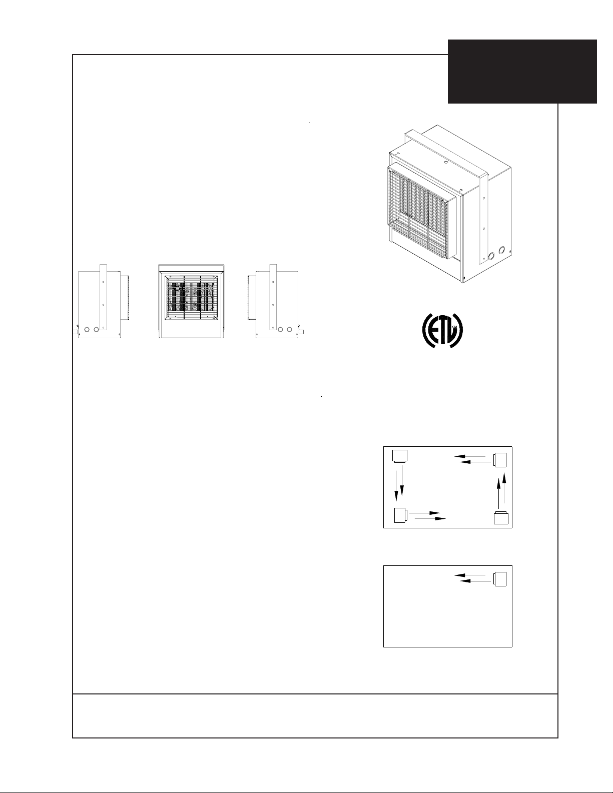
PROPER MOUNTING:
The heater(s) should be located along outside
walls or other areas of greatest heat loss. Multiple
heaters should be spaced to set up a generally
circular air movement, each heater supporting the
air stream of the other.
CONFORMS TO
ANSI/UL 1995
CERTIFIED TO
CAN/CSA C22.2 No. 236-11
EXPOSED
H
H
EXPOSED
EXPOSED
EXPOSED
L
I
S
E
T
110045
USC
D
H
H
H
IMPORT ANT : OWNER SHOULD RET AIN THESE INSTRUCTIONS FOR FUTURE REFERENCE
FORM: 8396-7/13
Page 2
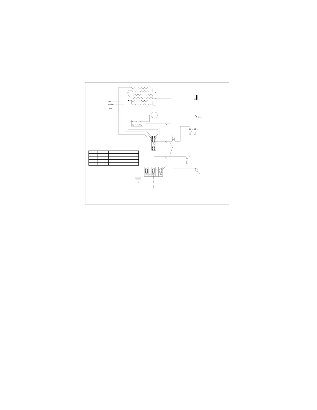
PRINCIPLES OF OPERATION
When the thermostat calls for heat, the elements are immediately energized, a fan delay brings on the fan
after the elements are heated allowing warm air to circulate. When the thermostat is satisfied, the elements are
de-energized and the fan purges the heater of residual heat.
The heater wattage may be field adjusted only on model HF5705T . Select the desired wattage from Table 1 and
move color coded jumpers as indicated.
ELEMENT
LIMIT
CONTROL
M
ABC
LTB
L2L1
240/208V 1?
BLACK
BLACK
RED
THERMOSTAT
RED
TABLE 1
WATTAGE ADJUSTMENT TABLE
VOLTS
WATTS
240/208
240/208
240/208
240/208
USE WITH MODEL NUMBER
NONE REQUIRED
5000/3750
BLUE JUMPER TO TERMINAL 'C'
4167/3120
BLUE AND YELLOW TO TERMINAL 'C'
3333/2500
BLUE,YELLOW AND RED TO TERMINAL ' C'
2500/1875
USE COPPER CONDUCTORS ONLY
CONTROL CIRCUIT WIRING MUST BE
NEC CLASS 1 RATED 600V
HF5705T
44503-001
FAN DELAY
ADJUSTMENT
INSTALLATION INSTRUCTIONS
All electric unit heaters are shipped fully assembled. Installation includes hanging the
unit and electrical wiring to the unit.
The wall and/or ceiling structure must be sufficient to support the combined weight of
the heater and any mounting bracket and accessories.
Be sure power source is de-energized before installing heater . Check heater voltage and
phase listed on heater data label on back of unit to make sure they are the same as the
electrical service supplied.
MOUNTING THE HEATER
Select the mounting location. Be sure to observe the minimum mounting clearances as
shown in Figure 1.
The heater can be mounted either from the ceiling or wall depending on the application.
The mounting bracket is supplied with 3/8” holes, 10 inches on center for threaded rod
mounting or direct mounting to the structure.
The heater cabinet also has 3/8” weld nuts 10” on center to allow threaded rod mounting
without the bracket.
FORM: 8396-7/13
Page 3

MOUNTING CONTINUED
1. Install the mounting bracket in the desired location with threaded rod or hardware
that is appropriate for the mounting surface. If using threaded rod, two nuts, one on
the top and one on the bottom of the bracket along with a split washer is suggested.
2. Secure the heater to mounting bracket, using the 1/4-20 x 3/4” machine
screws and lockwashers provided.
3. Position the heater, aligning the bracket holes with the cabinet holes and secure
bracket to the cabinet with the 1/4-20 x 1/2” machine screws and nuts that are
provided. With the mounting bracket in the vertical position the 1/4” nuts are not
necessary , weld nuts are supplied in the cabinet.
MINIMUM INSTALLATION CLEARANCES:
SIDES, TOP AND BOTTOM 0 INCHES
REAR: 8 INCHES (203mm)
FRONT: 24 INCHES (610mm)
Dégagements minimums MONTAGE:
Côtés, le haut et le bas 0 pouces
ARRIÈRE: 8 pouces (203mm)
AVANT: 24 pouces (610mm)
FIGURE 1
5.1
14.6
0"
14.4
10.0
W
A
L
L
0"
FLOOR
8.0"
MIN. TO WALL
24"
MINIMUM
DISTANCE
FROM FRON T
TO ANY
OBJECT
FORM: 8396-7/13
Page 4

POWER CONNECTION
T o avoid possible electrical shock, be sure the electrical current is turned off at
the main switch prior to wiring or servicing of unit.
1. Remove the access panel, by removing four screws, two on the front and two on the
back.
2. Remove desired knockout on side or back of the heater .
3. Following the correct unit wiring diagram, connect the power supply and electrical
ground to the correct terminals using accepted practices recognized by local codes.
See T able 2 for minimum circuit requirement s.
4. Replace the access panel, tighten the screws to ensure a good seal to help prevent
dust and dirt from entering the control compartment.
TECHNICAL DATA TABLE 2
MODEL VOLTS WATTS PHASE AMPS SUPPLY WIRE
HF5705T
H3H5705T 240/208 5000/3750 3 12.04/10.4 12
P3P5705T 480 5000 3 6.1
240/208
Note: Supply wire must be 60o AWG minimum.
5000/3750
1
20.83/18 10
14
OPERATION
1. Restore power to the unit.
2. Turn the thermostat up to energize the unit. When the area reaches the desired
temperature, rotate the thermostat knob counter- clockwise slowly until the heat turns
off.
3. This 5700 series is provided with a fan delay/purge. When the heater is turned on,
the elements will heat up before the fan comes on (approx. 30 seconds). This allows
for warm air circulation. When the thermostat is satisfied, the elements will
de-energize and the fan will continue to run (approx. 30 seconds) allowing residual
heat to be purged from the heater .
4. The 5700 series is provided with an automatic limit control. In the event of an
abnormal situation such as fan failure or other over-temp. situations the limit control
will cycle the heater off. In the event of an over-temp situation, the heater should be
inspected to determine the cause and repaired by authorized personnel.
FORM: 8396-7/13
Page 5

Maintenance:
Caution: Make certain that the power source is disconnected before attempting to service or disassemble
any component. If the power disconnect is out of the line of sight, lock it in the OPEN position and tag to
prevent the application of power.
Electrical:
Once a year inspect the control panel wiring to make certain insulation is intact and all connections are tight.
Inspect all heater and relay contacts. If the contacts appear badly pitted or burned, replace the contactor/
relay.
Cleaning:
Clean the unit casing, fan and motor once a year. A dirty motor will tend to run hot and eventually will be
damaged internally . Any rust spots on the casing should be cleaned and repainted.
The element can be cleaned by removing the outer cabinet. Do not use any liquid to clean electric components.
Lubrication:
All units have fan motors that are permanently lubricated so that only occasional cleaning is required.
General Safety Information:
CAUTION:
Follow all local electrical and safety codes, as well as the National Electric Code (NEC) and the Occupational
Safety and Health Act (OSHA).
To avoid possible electrical shock, be sure the electrical current is turned off at the main switch prior to
wiring or servicing of unit.
If the power disconnect is not integral and is out-of-sight, lock it in the open position and tag to prevent
unexpected application of power prior to performing any service of maintenance on the unit.
The unit when installed must be electrically grounded in accordance with the National Electrical Code and
standard industry practice.
Make certain that the power source conforms to the requirements of your equipment. See Table 2 for
information as to wire and circuit size.
Check heater voltage and phase on rating label to confirm it is the same as the electric service supply.
Wiring diagrams of the heaters and supply connections are permanently attached to the heater access door.
All terminals are coded in accordance with the wiring diagram.
The wall/ceiling mounting structure and anchoring provisions must be of sufficient strength to support the
combined weight of the heater and mounting bracket.
FORM: 8396-7/13
Page 6

44503-002
ELEMENT
CONTACTOR
COIL
FAN
DELAY
L3L2L1
480V 3 PH
LIMIT CONTROL
M
CONTROL TRANSFORMER
LTB
THERMOSTAT
CTB
USE WITH MODEL NUMBER
P3P5705T
44503-003
ELEMENT
CONTACTOR
COIL
FAN
DELAY
240V 3 PH
LIMIT CONTROL
CONTROL TRANSFORMER
LTB
L3L2L1
T-STAT
CTB
USE WITH MODEL NUMBER
H3H5705T
FORM: 8396-7/13
 Loading...