

Page 1
DC580
Digital Air Velocity Meter
The Value Leader
TM
www.testproductsintl.com
Page 2

Contents
Introduction ......................................... Page 1
General Overview & Guidelines ................. Page 1
Features and Guidlines ........................... Page 2
LCD Overview ....................................... Page 3
Keypad Overview ................................... Page 4
Probe Overview ..................................... Page 5
Turning the DC580 on & Connecting a probe ..Page 6
Units of Measure Setup Mode ................... Page 7
Duct Type and Size Setup Mode ................ Page 8
Definition of Free Area ........................... Page 9
Taking a Measurement ........................... Page 10
Selecting Between Air Velocity and Volume .. Page 11
Storing a Reading ................................. Page 11
Recalling a Stored Reading ..................... Page 12
Preparing to Traverse a Rectangular Duct .... Page 13
Time Based Traverse of a Horizontal Duct .... Page 14 - 16
Point Based Traverse of a Horizontal Duct .... Page 17 - 19
Preparing to Traverse a Round Duct ............ Page 20
Time Based Traverse of a Round Duct ......... Page 21 -23
Point Based Traverse of a Round Duct ......... Page 24 - 26
Traversing a Grille ................................. Page 27-28
Auto Off, Backlight, Hold and Min, Max, Avg.. Page 29
Bluetooth Activation & App Use.................. Page 30 - 34
Specifications ...................................... Page 35 - 36
Battery Replacement .............................. Page 36
Troubleshooting & Care............................ Page 37
Warranty, Service, Calibration ................... Page 37
Page 3

Introduction
Thank you for purchasing TPI brand products. The TPI DC580 digital air
velocity meter is a state of the art, easy to use air velocity tester designed to
display air velocity, air flow, and temperature. It can be used with the TPI
DC580 app to generate reports and store readings.
The DC580 can be ordered in several configurations:
Part Number
DC580C1 DC580 w/ Hotwire probe & Carry case
DC580C2 DC580 w/ Vane probe & Carry case
DC580C3 DC580 w/ Hotwire & Vane probes & Carry case
This manual covers all features for the DC580 and the use of both
hotwire and vane type probes.
Description
Features & Guidelines
Features:
• Measure air velocity and temperature simultaneously
• Field replaceable smart hot wire and vane probes
• Communicate with Android Smart Phone via Bluetooth LE and TPI App
• Display minimum, maximum & average
• Multiple measuring units: m/s, km/h, ft/min, knots, mile/h
Guidelines:
Always allow the DC580 sufficient time to acclimate to the test environ-
ment especially when moving from location to location.
Always operate the DC580 and probes within the temperature and
humidity limits outlined in the specifications area of this manual.
Never allow any object to enter the sensor area of the hotwire probe or
vane probe.
Never attach the DC580 magnetic boot to a hot surface.
1
Page 4
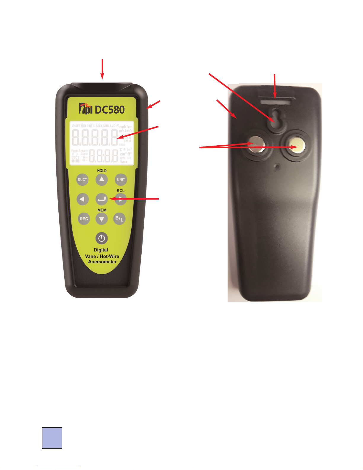
Instrument Overview
Rubber Boot
Display
Keypad
Probe Input
Jack
2
Magnets
Hanger Strap
Attachment
Point
Hanger Hook
Attachment
Point
DC580 Front
DC580 Back
Probe Input Jack - Connection point for hotwire and vane probes.
Rubber Boot - Protects the instrument from accidental damage
Display - Large 2 two line LCD display w/ backlight
Magnets - Used to attach the DC580 to metal surfaces
Keypad - Selects all available functions
Hanger Hook Attachment Point - Used with optional boot hook (p/n A103)
Hanger Stap Attachment Point - Used with optional magnetic hanger strap
(p/n A124)
Page 5
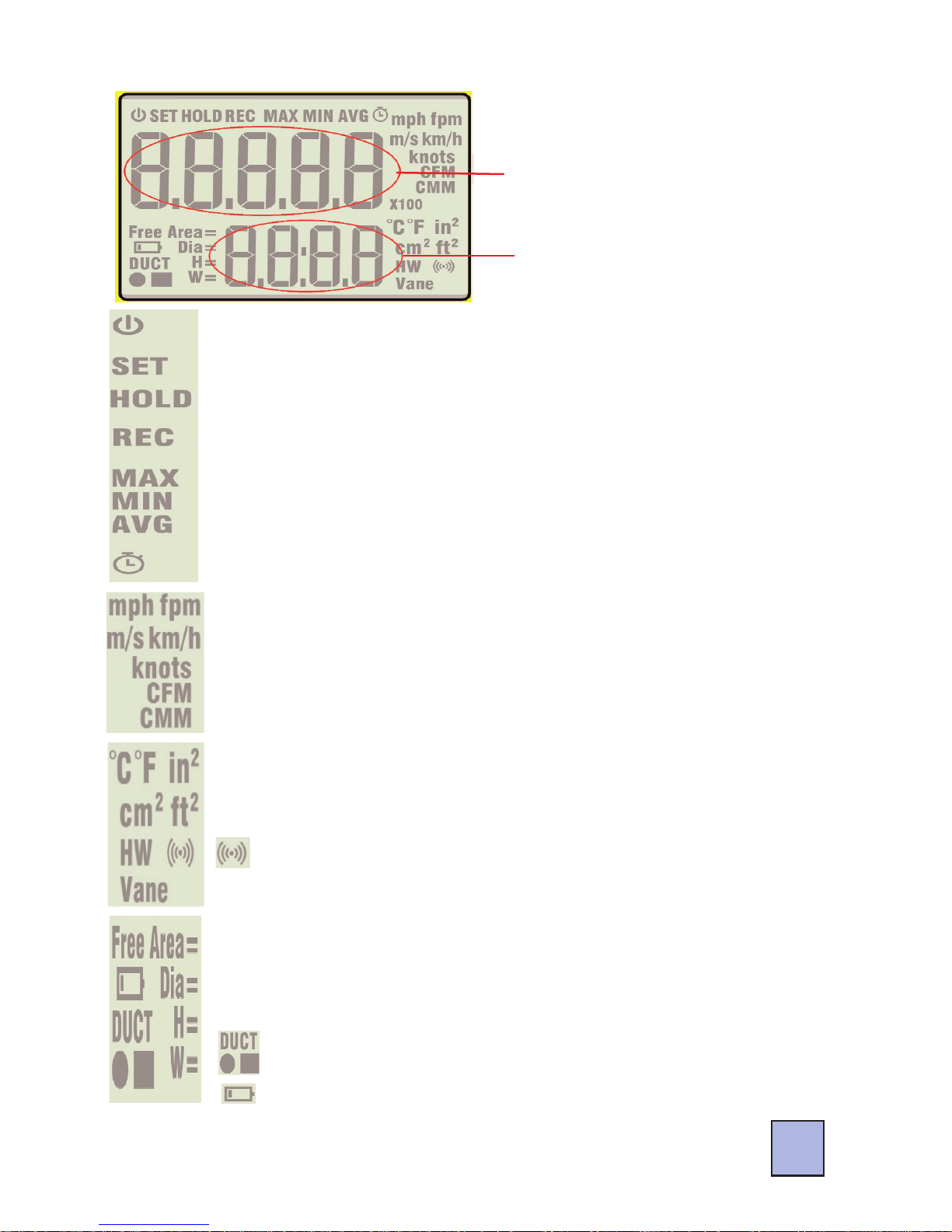
LCD Overview
Air Velocity and Air
Flow Volume Display
Area
Temperature Display
Area
Indicates timed record mode is active.
Indicates the displayed reading is the Maximum, Minimum,
or Average measurement.
Indicates Record mode is active.
Indicates Hold is active. Displayed readings freeze.
Indicates Set up mode is active.
Indicates auto power off is active.
Indicates units of measure for air velocity and volume.
mph = miles per hour, fpm = feet per minute,
m/s = meters per second, km/h = kilometers per hour, knots
CFM = cubic feet per minute,
CMM = cubic meters per minute
C F = Indicates temperature in Celsius or Fahrenheit.
cm2ft2= Duct size in square centimeters or square inches.
HW Vane = Indicates probe connection. Hot Wire or Vane.
= Indicates Bluetooth status.
Free Area = Amount of area blocked by grille, register, etc.
Dia = Diameter of duct if it is round
H = Height of duct if it is square or rectangular
W = Width of duct if it is square or rectangular
= Duct type, round or square. Also spot record indica-
tor.
= Low battery indicator. Replace batteries
when displayed.
3
Page 6

Keypad Overview
Use to navigate up in setup mode menus.
Use to freeze the current reading on the LCD when performing a
measurement.
Use to confirm entry when in setup mode menus.
Use to switch between air velocity and air flow when taking measurements.
Use to activate memory mode and store readings.
Use to decrease the parameter in setup mode menus.
Use to activate and deactivate auto power off.
Use to turn the DC580 on and off. (Press and hold)
Use to setup duct type and size.
Use to navigate left in menu mode.
Use to activate time and point record modes and to cycle
through min, max, and average readings.
Use to setup units of measurement for air velocity, air volume, temperature, and duct size.
Use to return to normal operation from recall mode.
Use to navigate right in setup mode menus.
Use to recall and display recorded measurements.
Use to turn the backlight on and off.
Use to activate Bluetooth communication mode.
4
Page 7
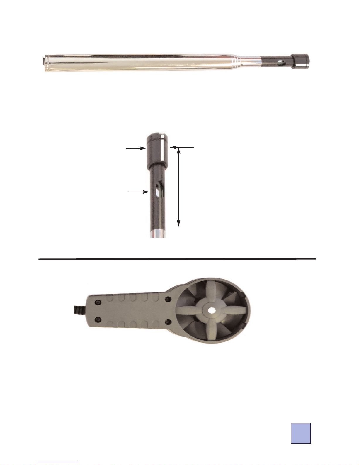
Probe Overview
Hot wire probe for the DC580. This probe can be used to measure
air velocity and flow inside ducts. The white dot should face into
the air stream. The probe can be expanded by pulling out the sensor shaft enabling the probe to extend like an antenna.
Temperature
Sensor
Air velocity sensor
underneath protective
hood.
Slide the sensor protective
hood all the way down to
perform air velocity measurements. Make sure the
temperature sensor is not
covered.
Replace the cover when
not in use.
Hot Wire Probe Sensors
Hot Wire Probe (Part number A581)
Vane Probe (Part number A582)
Vane probe for the DC580. This probe can be used to measure air
velocity and flow at registers, hoods, and other openings. The
white line/dot should face into the air stream.
Note: The DC580 can be purchased to include one or both of
these probes. These probes are also available for purchase separately. Please see page 36 for information on kits and probes.
5
Page 8

Turning the DC580 on and Connecting a Probe
6
To turn the DC580 on press and hold the key for more than two
seconds.
If a probe is not connected the display will read ‘oPEn’. When this
is displayed only the and keys operate.
When a probe is connected the DC580 will auto detect which probe
has been connected and will act accordingly.
Hot wire probe - Make sure the hotwire probe cover has been put
into the closed position before connecting the probe. When the hot
wire probe is connected a 5 second warm up period will begin and
the display will read ‘H---d’ and display the countdown. After the
countdown the DC580 is ready to take measurements. Slide the
cover down to the open position and perform tests.
Vane Probe - Connect the vane probe and the DC580 is ready to
take measurements.
After power is turned on and a probe is connected the DC580 is
ready to take measurements. Use the setup modes as needed to
adjust units of measure and duct size.
Page 9

Units of Measure Setup Mode
7
Setup the units of measure to be used. The meter will default to
these settings upon start up. These can be changed as necessary.
1. Connect a probe to the DC580. Turn the DC580 on by pressing
and holding the key for more than 2 seconds.
2. Press the key to enter the units of measure setup mode. The
air velocity annunciator will begin flashing.
3.Use the key to cycle through the air velocity units until the
required unit is shown. Press the key to move to the air flow
units.
4. Use the key to cycle through air flow units. CFM and CMM are
available. When the desired unit is displayed press the key to
move to temperature units.
5. Press the key to cycle between temperature units. ºF and ºC
are available. When the desired unit is displayed press the key
to move to duct dimension units.
6. Press the key to cycle through the duct dimension units.
Inches (in), centimeters (cm), meters (m), and feet (ft) are available.
When the desired unit of measure is displayed press the key.
7. The DC580 exits the units setup menu and returns to normal operation.
Note: At any time in the above procedure the key can be
pressed to return to normal operation. Units of measure that were
not adjusted will remain unchanged.
Page 10

Duct Type and Size Setup Mode
8
When measuring air velocity, the volume of air or airflow can be displayed. This is a calculation based on the duct type and size. For air
flow to be accurate the duct size needs to be entered into the
DC580.
The units of measure used in the duct size can be set by following
the steps outlined in section page 7.
1. Connect a probe to the DC580 and turn it on as outlined earlier.
2. Press the key to activate duct size entry mode.
3.Use the key to cycle through the duct type. The types are
round, rectangular, and free area. Select free area if measuring at a
supply or return with an obstruction like a grille. NOTE: The free area
of the duct must be known. This is published by the grille manufacturer.
4. Once the duct type is displayed, =round, =rectangular, or free
area press the key to confirm the selection.
Round Duct - Use the keys to enter the diameter
of the duct. Press the key to confirm the selection.
Rectangular Duct - Use the keys to enter the
height (H) of the duct. Press the key to confirm the selection.
Use the same keys to enter the width (W) of the duct. Press the
key to confirm the selection.
Free Area - Use the keys to enter the free area of
the duct. Press the key to confirm the selection.
For more information on free area please see the next page.
Page 11

Definition of Free Area
Free Area is the total area in which air flows through a supply outlet or a return grille. Free area is the effective area of the outlet or
grille and takes into account any restrictions.
If a grille is not used and there is no restriction on the area in
which air flows then the free area is equal to the actual area. This
is the case when measuring air flow at the middle of a duct, or if
the grille is removed from the return or supply duct.
When measuring airflow with a grille in place or restriction present,
the free area is the total area minus the area covered by the
restriction (grille fins).
Grille manufacturers publish free area specifications and this is the
most accurate information to use when setting up your DC580 to
measure air flow (volume).
Whenever possible it is best to use free area when entering duct
size. This will ensure the most accurate air flow reading.
9
Page 12

Taking a Measurement
10
1. Insert the hot wire or vane air velocity probe into the DC580. If
the hotwire probe is used make sure the sliding cover is over the
air sensor. (See page 5)
2. Press and hold the key until the DC580 turns on.
3. If the hotwire probe is used the DC580 will countdown from 5.
During this time the hotwire sensor is being warmed up. If the
vane probe is used there will be no countdown.
4, If necessary, set the units of measure and duct size as outlined
on page 7 and 8.
5. Insert the air velocity probe into the air stream with the white dot
facing into the air. If the hotwire probe is being used make sure the
sliding cover is in the down position and the sensor is exposed.
6. The air velocity will be displayed in the upper display and the
temperature will be displayed in the lower display.
The most accurate way to take a reading of a duct or grille is to
traverse it and take the average reading. The DC580 can do this
without the need of manual calculations.
The following pages include instructions for traversing ducts and
grilles along with various features and functions available on the
DC580.
Page 13

Selecting Between Air Velocity and Volume (Air Flow)
Display shows air velocity
in fpm and temperature
Press the Enter
key to toggle
the display.
Display shows air flow
(volume) in CFM and
temperature
11
When an air velocity is displayed on the DC580 the key can be
pressed to toggle the top display between air velocity and air flow.
Note: The duct size must be entered correctly for the air flow reading to be accurate. Air flow is a calculation based on the duct size
and the measured air velocity.
Storing a Reading
The displayed reading can be stored in memory. This will store the
air velocity, air volume, and temperature.
1. When taking a measurement, once the
reading is on the display press the key.
2. The display will prompt you for a memory
location to store the reading. To cancel
press the key or use the keys to select the
memory location to store the reading then press the key.
Clearing Memory: Saving data to the same memory location will
write over the data already saved. All locations can be cleared by
pressing the key to enter memory mode then pressing and
holding the key for approximately 3 seconds.
Page 14

Recalling a Stored Reading
Stored readings can be recalled and displayed on the DC580.
1. With the DC580 in normal operation press the key.
2. The display will prompt
you to select a memory
location to display the
stored reading.
3. Use the keys to select the memory location to
display.
4. The stored reading will
be displayed.
Press the key to toggle
between the stored
air velocity and air volume.
5. Press the key to exit recall and return to normal operation.
Stored information can also be sent to the DC580 App. The app
will display the duct size and also provides the ability to export the
data to a CSV file or send a report via email. Please see page 30
for more information on the app.
Stored air
velocity and
temperature
displayed.
Press the
enter key to
toggle the
display.
Stored air
volume is
displayed.
12
Page 15

Preparing to Traverse a Rectangular Duct
To do a proper airflow measurement (CFM) you should do traverse
readings to obtain the true average airflow through the duct. It is recommended to do at least 12 points of measurement. There are two
ways to perform this test using the DC580, Time Based Traverse and
Spot Based Traverse. Time based is typically easier but both are
explained in the next sections.
1. You will need to determine the easiest access to take your readings. Normally it is best to enter from the side (Height) of the duct
since you will have to drill less holes, but you may have to drill from
the bottom (Width) of the duct. See below.
Not the ideal side to enter
the duct but may be necessary
Choose one
side to enter
the duct.
Ideal side to
enter the duct.
13
Page 16

Time Based Traverse of a Horizontal Duct
Press the Up Arrow key repeatedly
until the timer symbol is seen.
14
1. Insert the hotwire probe into the DC580 and turn the meter on.
2. Enter the duct type and size and prepare the duct for transverse
measurements as outlined on page 13.
3. Press the key. The display will prompt for time or point based
traverse. Use the key to select time based traverse record.
4. Press the key to confirm the selection.
5. Insert the hotwire probe all the way into the duct at the first hole.
Make sure the white dot is facing the air flow. HINT: If you turn the
probe you will see the readings change up or down, when the
reading is at the highest you are in the proper position.
Page 17

Time Based Traverse of a Horizontal Duct (Continued)
Start with the probe all
the way into the duct.
Press the key.
Slowly pull the probe
to the entrance hole.
Before removing the
probe see step 8.
15
6. With the probe in place press the key and the DC580 will
begin recording.
7. Slowly pull the probe towards the entrance point of the duct.
8. Stop at the last measurement point prior to pulling the probe out of
the duct. Press the key to pause the recording.
Page 18

Time Based Traverse of a Horizontal Duct (Continued)
16
9. Pull the probe out and insert it into the next test hole all the way
into the duct.
10. Press the key to begin recording. Repeat these steps for
all test holes.
11. When the duct has been completely traversed and prior to
pulling the probe out of the last test hole, press the key to
pause the recording.
12. Press the key to store the readings. See section page 11
on storing readings. This will store the average air velocity, air
volume, and temperature readings.
13. If another traverse needs to be made press the key to
clear the timer and begin traversing a duct.
If finished, press and hold the key to exit record and return
to normal operation. The stored readings can be recalled and
displayed (see page 12) or sent to the DC580 app (see page
30).
Note: At any time during the traverse process when REC is displayed the key can be pressed to cycle through the minimum (MIN), maximum (MAX), and average (AVG) readings.
Page 19

Point Based Traverse of a Horizontal Duct
1. Insert the hotwire probe into the DC580 and turn the meter on.
2. Enter the duct size and prepare the duct for transverse measurements as outlined on the previous page.
3. Press the key. The display will prompt for time or point based
traverse. Use the key to select point based traverse record.
4. Press the key to confirm the selection.
5. Divide the duct into at least 12 equal boxes, you will need to take
the reading in the center of each box. Be sure that the sample
points are no more than 4 inches apart from center to center. If
needed you can add more sample points (boxes) to cover larger
duct sizes. Insert the hotwire probe all the way into the duct at the
first hole. Make sure the white dot is facing the air flow.
Press the Up Arrow
key repeatedly until
the timer symbol is
seen.
17
Page 20

Point Based Traverse of a Horizontal Duct (Continued)
Start with the probe all
the way into the duct.
Press the Enter key.
Slowly pull the probe
to the entrance hole.
Stop at each point and
press the Enter key.
18
6. With the probe in place press the key to record the reading.
7. Slowly pull the probe towards the entrance point of the duct. Stop
at each point and press the key to record reading.
8. Pull the probe out and insert it into the next test hole all the way
into the duct.
Page 21

Point Based Traverse of a Horizontal Duct (Continued)
19
9. Press the key to record the reading. Repeat these steps for
all test holes.
10. When the duct has been completely traversed press the
key to store the readings. See section page 11 on storing readings. This will store the average air velocity, air volume, and
temperature readings.
11. If another traverse needs to be made press the key to clear
the counter and begin traversing a duct.
If finished, press and hold the key to exit record and return
to normal operation.
Note: At any time during the traverse process when REC is displayed the key can be repeatedly pressed to cycle through
the minimum (MIN), maximum (MAX), and average (AVG) readings.
Page 22

Preparing to Traverse a Round Duct
20
Preparing the Duct
To do a proper airflow measurement (CFM) you should do traverse
readings to obtain the true average airflow through the duct. You will
need to drill 2 holes at 90 degrees to each other, similar to the drawing below.
1. Take your measurements by inserting the hotwire probe into the
drilled hole. and use the insertion depth chart to determine how far in
the duct you will go for each point. Then you will repeat for the other
hole.
2. Be sure you have the tip of the hotwire pointed into the flow of air,
there is a white dot on the tip, this should be inline with the flow.
HINT: If you turn the probe you will see the readings change up or
down, when the reading is at the highest you are in the proper position.
Page 23

Time Based Traverse of a Round Duct
Press the Up Arrow key repeatedly
until the timer symbol is seen.
21
Using Time Based Traverse Record Function
1. Insert the hotwire probe into the DC580 and turn the meter on.
2. Enter the duct type and size. Prepare the duct for transverse
measurements as outlined on the previous page.
3. Press the key. The display will prompt for time or point based
traverse. Use the key to select time based traverse record.
4. Press the key to confirm the selection.
5. Insert the hotwire probe all the way into the duct at the first hole.
Make sure the white dot is facing the air flow.
Page 24

Time Based Traverse of a Round Duct (Continued)
Start with the probe all
the way into the duct.
Press the key.
Slowly pull the probe
to the entrance hole.
Before removing the
probe see step 8.
22
6. With the probe in place press the key and the DC580 will
begin recording.
7. Slowly pull the probe towards the entrance point of the duct.
8. Stop at the last measurement point prior to pulling the probe out of
the duct. Press the key to pause the recording.
Page 25

Time Based Traverse of a Round Duct (Continued)
23
9. Pull the probe out and insert it into the other test hole all the way
into the duct.
10. Press the key to begin recording. Repeat these steps for
all test holes.
11. When the duct has been completely traversed and prior to
pulling the probe out of the last test hole, press the key to
pause the recording.
12. Press the key to store the readings. See section page 11
on storing readings. This will store the average air velocity, air
volume, and temperature readings.
13. If another traverse needs to be made press the key to
clear the timer and begin traversing a duct.
If finished, press and hold the key to exit record and return
to normal operation.
Note: At any time during the traverse process when REC is displayed the key can be repeatedly pressed to cycle through
the minimum (MIN), maximum (MAX), and average (AVG) readings.
Page 26

Point Based Traverse of a Round Duct
1. Insert the hotwire probe into the DC580 and turn the meter on.
2. Enter the duct type and size. Prepare the duct for transverse
measurements as outlined on the previous page.
3. Press the key. The display will prompt for time or point based
traverse. Use the key to select point based traverse record.
4. Press the key to confirm the selection.
5. Divide the duct into at least 10 equal boxes, you will need to take
the reading in the center of each box. Be sure that the sample
points are no more than 4 inches apart from center to center. If
needed you can add more sample points (boxes) to cover larger
duct sizes. Insert the hotwire probe all the way into the duct at the
first hole. Make sure the white dot is facing the air flow.
Press the Up Arrow
key repeatedly until
the timer symbol is
seen.
24
Page 27

Point Based Traverse of a Round Duct (Continued)
Start with the probe all
the way into the duct.
Press the key.
Slowly pull the probe to the
entrance hole. Stop at each
point and press the key.
Stop at each point and
press the Enter key.
25
6. With the probe in place press the key to record the reading.
7. Slowly pull the probe towards the entrance point of the duct. Stop
at each point and press the key to record reading.
8. Pull the probe out and insert it into the other test hole all the way
into the duct.
Page 28

Point Based Traverse of a Round Duct (Continued)
26
9. Press the key to record the reading. Repeat these steps for
all the other test hole.
10. When the duct has been completely traversed press the
key to store the readings. See page 11 on storing readings. This
will store the average air velocity, air volume, and temperature
readings.
11. If another traverse needs to be made press the key to clear
the counter and begin traversing a duct.
If finished, press and hold the key to exit record and return
to normal operation.
Note: At any time during the traverse process when REC is displayed the key can be repeatedly pressed to cycle through
the minimum (MIN), maximum (MAX), and average (AVG) readings.
Page 29

3. Traversing a Grille
Press the Up Arrow key repeatedly
until the timer symbol is seen.
27
Using Time Based Traverse Record Function
1. Insert the vane probe into the DC580 and turn the meter on.
2. Enter the duct type and size. Remove the grille if possible or use
the free area specification from the manufacturer.
3. Press the key. The display will prompt for time or point based
traverse. Use the key to select time based traverse record.
4. Press the key to confirm the selection.
5. Put the vane probe so the white dot is facing the air flow. Press
the key to begin recording.
Page 30

3. Traversing a Grille (Continued)
28
6. Slowly move the vane across the grilled towards the other end.
Start
End
7. Stop at the last measurement point prior to removing the vane.
Press the key to pause the recording.
8. Press the key to store the readings. See page 11 on storing
readings. This will store the average air velocity, air volume, and
temperature readings.
9. If another traverse needs to be made press the key to clear
the timer and begin traversing a duct.
If finished, press and hold the key to exit record and return to
normal operation.
Note: At any time during the traverse process when REC is displayed the key can be pressed to cycle through the minimum
(MIN), maximum (MAX), and average (AVG) readings.
Page 31

Activate / Deactivate Auto Power Off
29
The DC580 always defaults to auto power off mode. When auto
power off is activated the annunciator will show in the upper left
corner of the display.
To deactivate auto power off from normal operation mode press
and hold the key until the annunciator turns off. Press and
hold the key again or turn the meter off and on to activate auto
power off.
Turning the Backlight On/Off
The backlight can be turned on to make it easier to see the display
in dim areas.
From normal operation mode press the key to turn the back
light on. Press the key again to turn the backlight off.
NOTE: The backlight will automatically turn off after approximately
one minute. This is not adjustable and is done to maximize battery
life.
Turning Display Hold On/Off
The displayed reading can be held on the display if needed.
From normal operation mode during a measurement press the
key to hold the displayed reading. Press the key to unhold the
reading and return to normal operation.
Minimum, Maximum, Average
The minimum, maximum, and average reading can be displayed
using the Record function.
At any time when REC is active like while performing a traverse
measurement the key can be repeatedly pressed to cycle
through the minimum (MIN), maximum (MAX), and average (AVG)
readings.
Page 32

Activate / Deactivate Bluetooth
Bluetooth can be activated in order to communicate with the
DC580 app.
1. Activate Bluetooth by pressing and holding the key until the
annunciator shows in the lower right corner of the display. The
annunciator will blink until connected to a phone.
2. Deactivate Bluetooth by pressing and holding the key until
the annunciator turns off. Turning the DC580 off will also deactivate Bluetooth.
Using the DC580 App
Connecting to a DC580
Download the DC580 app from the app store.
1. Insert a probe in the DC580 and turn it on. Activate Bluetooth as
outlined above.
2. Open the app. The main
screen will be displayed.
3. Tap on “Connect” to search
for available DC580 devices.
30
Page 33

Using the DC580 App (Continued)
4. Available DC580’s will be displayed.
5. Tap on an available DC580 and the
app will return to the main display.
From the main display many functions can be accessed.
The real time Air Volume, Air Velocity,
and Temperature can be displayed.
Readings stored in the DC580 memory
can be downloaded and seen.
Your company information can be
entered into the app. This information will
show up on email reports.
The customer information can be entered
into the app, This information will show
up on email reports.
Settings like if a grille is present or what
type of duct is being tested can be
entered.
All of these can also be
accessed from the drop
down menu tab.
31
Page 34

Using the DC580 App (Continued)
Tap on “Volume, Temp, Velocity” to see
the real time readings.
From this screen the auto power off,
units of measure, and duct type / size
can be changed by tapping on the icons
and entering the data.
This information will be transmitted to the
DC580.
Tap on “Reading Mem Data” to download
all saved readings from the memory of the
DC580.
Tap on “Update All” to begin the download.
The memory locations being downloaded
will be displayed. Only locations with data
will download.
Tap on a memory location to see the information contained in it. (See next page)
NOTE: Downloading information from the
DC580 does not delete the data on the
DC580. To do this either store over older
data or perform a memory clear as outlined
on page 11.
32
Page 35

Using the DC580 App (Continued)
After tapping on “Reading Mem Data”
and tapping “Update All” the data stored
in the DC580 will download.
Tapping on a memory location will display the information stored there.
From here a CSV file can be created
and stored on the phone by tapping CSV
or the CSV file can be created and
emailed by tapping email.
Tap on “Company Information” to open the
Company Info input screen. This is where
your company name, address, and email
should be entered.
This information will be part of the CSV
report generated that you can email your
customer.
33
Page 36

Using the DC580 App (Continued)
Tap on “Customer Information” to open
the Customer Info input screen. This is
where your customer’s name, address,
and email should be entered.
The building information can also be
entered as necessary.
This information will be part of the CSV
report generated that you can email your
customer.
Tap on “Settings” to open the Settings input
screen. This is where you select whether
there was a grille in place and what type of
duct was being measured.
This information will be part of the CSV
report generated that you can email your
customer.
34
Page 37

Specifications
35
Page 38

Specifications (Continued)
Optional Accessories
Part Number Description
A103 Boot hook for hanging the DC580
A124 Magnetic hanger strap for hanging the DC580
Replacement Parts
Part Number
Description
DC580 Meter only
A580 Carrying case for DC580
A581 Hotwire probe for DC580
A582 Vane probe for DC580
A583 Protective boot with magnets
Battery Replacement
1. Remove the DC580 from the protective boot by prying the boot
off from the bottom of the meter first.
2. Locate and loosen the battery cover screw.
3. Remove the battery cover and replace the batteries (AA x 3).
4. Install the battery cover and tighten the cover screw. Install the
protective boot at starting by inserting the top of the meter into
the boot first.
36
DC580 battery compartment.
DC580 battery
cover screw.
DC580 battery
cover removed.
DC580 with the
boot removed.
Page 39

Troubleshooting
Problem Possible Solution
DC580 will not turn on Change the battery.
Press and hold the key.
Display reads OPEN Connect a probe to the input.
Probe may be bad; Return for service.
Cannot connect Bluetooth Turn Bluetooth on, see page 30.
Make sure phone Bluetooth is on.
Readings seem to be high or low Change batteries.
Ensure white dot is facing into the air
stream.
Care & Cleaning
Clean the DC580 with a soft lint free cloth. Do not attempt to clean the sensor. Use a mild detergent on the base unit if necessary.
Do not submerse the DC580 or probes.
Warranty, Service, and Calibration
The TPI DC580 air velocity meter is guaranteed free from defects in mate-
rials and workmanship for 3 Years from the date of purchase. This guarantee
does not affect your statuary rights. For additional information please refer to
the included warranty card or contact TPI at 800-368-5719.
optimum performance, calibration is recommended once every year.
To obtain warranty performance, service or calibration of your meter: Include with the product your name, address, phone number, written description of the problem and proof of purchase date. Carefully package and return
to:
. To maintain
TPI / Attn. Service
9615 SW Allen Blvd. Suite 104
Beaverton, OR 97005
37
Page 40

Test Products International, Inc.
9615 SW Allen Blvd., Ste. 104
Beaverton, OR 97005
Tel: 503-520-9197 Fax: 503-520-1225
www.testproductsintl.com
Test Products International, Ltd.
342 Bronte Road South, Unit #6
Milton Ontario Canada L9T5B7
Tel: 905-693-8558 Fax: 905-693-0888
www.tpicanada.com
Test Products International Europe Ltd.
Longley House International Drive
Southgate Crawley
West Sussex RH10 6AQ
Tel: +44 (0) 1293 530196 Fax: +44 (0) 1293 531870
www.tpieurope.com
 Loading...